 Junhui Zhang
 Feng Li1
 Shiping Zhang
95% of researchers rate our articles as excellent or good
Learn more about the work of our research integrity team to safeguard the quality of each article we publish.
Find out more
ORIGINAL RESEARCH article
Front. Earth Sci. , 20 September 2021
Sec. Geohazards and Georisks
Volume 9 - 2021 | https://doi.org/10.3389/feart.2021.757724
This article is part of the Research Topic Landslide Hazards in Alpine Region: Mechanics and Mitigation View all 23 articles
An anchoring frame beam is a very common form of support for reinforced slopes, especially in alpine regions. Centrifugal tests have proved to be an intuitive and effective means of investigating the mechanism of action of frame beams. However, the data acquisition system of the geotechnical centrifuge in service has the problem of a small number of acquisition channels. A multi-channel selector based on the existing acquisition system was proposed, designed, processed, and manufactured, and it was debugged, tested, and applied in a no-load centrifugal test, static pressure model test, and centrifugal model test. The results show that the acquisition mode of the multi-channel selector connected with a maximum of 288 sensors has been changed from “one-to-one” to “one-to-many”. Its influence on various sensor signals is negligible. The multi-channel selector can work normally, which communicates and feeds back with the remote controller in the 1–120 g no-load centrifugal test. In the static load model test, 162 sensor signals were well collected through it. And only 51 channels were used to effectively obtain the signals of 187 sensors in a 70 g centrifugal model test of an anchoring slope with a frame beam. The multi-channel selector can be successfully applied in different use environments, saving time and reducing the cost of obtaining a single set of data.
Landslides (Amato et al., 2019; Carlà et al., 2019; Kreczmer et al., 2021) occur every year around the world, especially in alpine regions (Zhang J. et al., 2021; Zheng et al., 2018; Zhou et al., 2021). An anchoring frame beam is a very common form of support for reinforced slopes (Lin et al., 2017; Shi et al., 2019; Zheng et al., 2021b). Various research methods, such as theoretical analysis (Wang et al., 2020; Zeghal et al., 2018; Zhang S. et al., 2021; Zheng et al., 2021a), laboratory tests (Pan et al., 2020; Yao et al., 2020; Zhang et al., 2020b), numerical simulations (Ge et al., 2017), and on-site monitoring (Zhang et al., 2020a; Zhao et al., 2020) were used to study the mechanism and prevention of landslides. The physical model test is the most commonly used entity research method (Ghandil et al., 2016), which is widely used in many disciplines such as geotechnical, hydraulic, structure, etc. (Lin et al., 2018). Among them, the geotechnical centrifugal model test is becoming more and more popular with researchers, because it uses the super-gravity field to make the test object obtain the internal stress state of its weight similar to the prototype, thereby effectively ensuring that the static/dynamic response, stress path, deformation, and failure mechanism of the test body are highly consistent with the prototype (El Sawwaf et al., 2006; Chen et al., 2018; Weng et al., 2020). It is generally recognized by international engineering and academic circles. With the continuous advancement of centrifuge construction technology and the substantial expansion of the scope of test applications, most of the geotechnical centrifuge equipment has basically improved the technology in the simulation of static/dynamic conditions. It is well known that the construction and maintenance costs of geotechnical centrifuges are enormous, leading to high costs for each centrifugal model test, so it is desirable to collect as much test data as possible. However, a static and dynamic data acquisition system with many geotechnical centrifuges in service is usually equipped, which carries tens or hundreds of channels for connecting various sensors in a “one-to-one” manner. As a result, the number of data obtained in many centrifugal model tests cannot exceed the number of channels of the data acquisition system, which inevitably causes the data of each channel to be expensive. Therefore, it is very meaningful to obtain more data based on the number of channels of the existing acquisition system to reduce the cost of a single dataset in a centrifugal model test.
Many scholars have carried out centrifugal model tests and obtained a large amount of test data (Ng et al., 2004; Thusyanthan et al., 2007). However, all were limited by the number of channels in the data acquisition system, and the number of sensors used in a test was relatively small (Li et al., 2019; Shen et al., 2020). Viswanadham et al. (2009) studied geotextile-reinforced slopes subjected to differential settlements during centrifuge at 40 g, and five datasets of Linearly Variable Differential Transformer (LVDT) were collected. Chortis et al. (2020) researched the influence of scour depth and type for monopiles in sand under monotonic lateral loading by geotechnical centrifuge. Twenty strain gauges were embedded at different depths on the left and right sides of the model pile. Sabagh et al. (2020) used seven sensors (five found surface settlement LVDT, two tunnel displacement LVDT) and one camera to study the response to a continuous shallow tunnel crossing an active normal fault. Liu et al. (2011) carried out the centrifugal model test of the deformation mode of the geosynthetic structure-reinforced soil wall under seismic load during service life and reinforcement load. A total of thirty-six sensors including eight LVDTs, sixteen strain gauges, and twelve accelerometers were installed. In the centrifugal model test of Rotta et al. (Rotta Loria et al., 2015), ten strain gauges were attached to each of the three energy piles in order to obtain the energy of thermo-mechanical loads that the piles were subjected to in saturated sand. Ueda et al. (2019) researched a pile model which they embedded in an inclined ground and subjected to liquefaction-induced lateral spreading using four different centrifugal accelerations from 13 to 50 g, and six pore water pressure transducers, six accelerometers, twelve strain gauges, four laser-displace sensors, and one thermocouple were obtained. The research of Wang et al. (2019) and Yang et al. (2019) were about the performance and load-bearing characteristics of the single friction wheel foundation of offshore wind turbines under lateral moment loads and the vertical performance in the sand, and only one LVDT was used in their tests. Some researchers (Kutter et al., 2018; Sahare et al., 2020) carried out Liquefaction Experiments and Analysis Projects (LEAP). The centrifugal models were equipped with 14 accelerometers and 10 pore pressure transducers, and 20 data acquisition channels were utilized.
In addition, other measurement technologies such as cameras, optical fibers, wireless transmission (Bluetooth, radio, 4G, etc.) were also used in the centrifugal model test (Gourc et al., 2010; Herbert et al., 2011; Kuang et al., 2011). It was an effective supplement to the data acquisition system that comes with the existing centrifuge. However, many problems in the test process (untimely test data acquisition, too much invalid data, poor synchronization, etc.) increased the risk of test failure. Cao et al. (2018) tested a method for estimating soil moisture using an active heating fiber Bragg grating (FBG) sensor. Among them, a FBG acquisition instrument was fixed on the rotating arm of the centrifuge, and it rotated with the rotating arm during the test. At this time, the collected test data could not be viewed. Broekman et al. (2020) developed a linear drive system that provides closed-loop control in cyclic, monotonic, or static load or displacement control, and CCTV cameras were used in the centrifuge.
Thus, the objective of this paper was to propose a multi-channel selector design and successfully use it for centrifugal model testing of an anchoring slope with a frame beam to achieve the purpose of reducing the cost of a single data test. This study was organized as follows. First, the multi-channel selector was designed and manufactured, and its workflow was introduced. Then, a set of sensors such as earth pressure gauges, laser displacement gauges, strain gauges, etc., were selected to be connected to the multi-channel selector and then connected to the data acquisition system and compared with the directly connected data acquisition system. Finally, the multi-channel selector was applied in a centrifugal model test of an anchoring slope with a frame beam, and 187 sets of data were successfully obtained and analyzed.
The multi-channel selector was designed based on the dynamic data acquisition system supporting the geotechnical centrifuge of Changsha University of Science and Technology. The system could collect 64 sets of channel data at one time, including 32 sets of voltage data, 16 sets of electron current data, and 16 sets of strain data.
The hardware of the current data acquisition system was connected by the data acquisition computer, the terminal next to the model box, and various sensors as shown in Figure 1A. Their connection method was that one terminal can only connect to one sensor, which can be called one-to-one. Therefore, the geotechnical centrifuge data acquisition system was equipped with a panel containing 64 terminals next to the model box, and only 64 sensors can be connected at most. The multi-channel selector was set between the original terminal and the sensor, and was connected to them with a shielded cable, as shown in Figure 1B.
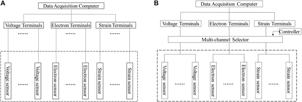
FIGURE 1. Hardware connection diagram: (A) current connection; (B) added multi-channel selector.
Taking the voltage connection terminals numbered A in Figure 2 as an example, the working principle of the multi-channel selector can be introduced in detail as follows. It contained one total output port (A), six input ports (A1∼A6), and six dual control switches (S1∼ S6). Generally, all switches were open, and port A had no voltage. When the control angle was energized so that the control switch NO.S1 was closed and the remaining switches were open, the circuit between the input terminal A1 and the output terminal A was connected. Then, two-core shielded cables that transmit signals “+” and “-” were used to connect the terminal block and the multi-channel selector. At this time, the hardware connection between the sensor signal connected to the input terminal A1 and the data acquisition computer was realized, and its signals using the current acquisition software were collected, stored, and displayed. Similarly, when the control switch NO.S2 was closed when the remaining switches were open, the sensor signal connected to input port A2 was collected, stored, and displayed. By analogy, the signals of the six input ports could be collected, stored, and displayed. Thereby, multiple sensor signals were obtained using one terminal, which can be called “one-to-many”. Each channel terminal was extended to connect six sensors. And taking eight terminals as a group in our centrifuge, if eight terminals were connected to a multi-channel selector, forty-eight sensors could be expanded, as shown in Figure 3. The connection mode was changed from “one-to-one” to “one-to-many”, so that more sensor signals were collected, stored, and displayed.
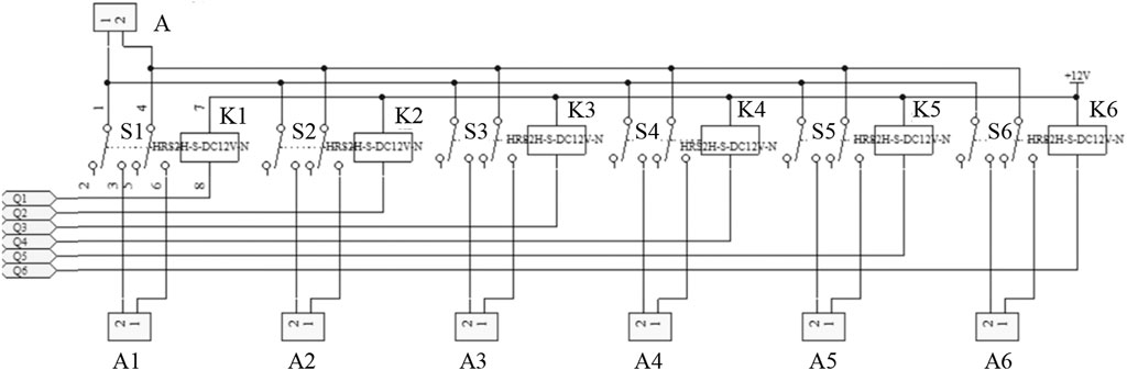
FIGURE 2. Multi-channel selector connection diagram.
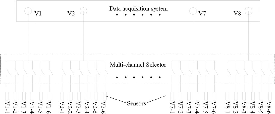
FIGURE 3. Multi-channel selector connection diagram.
In order to achieve the above purpose, a circuit diagram and circuit board were designed and processed, as shown in Figure 4. One set of sixteen-pin output plugs, eight sets of twelve-pin input plugs, and one row of light-emitting diodes were installed on both sides of the multi-channel selection board. In addition, forty-eight dual-control switches, one eight-to-one analog switch, one single-chip microcomputer, one dial switch, and one RS485 signal transceiver were welded on the front. The input and output terminals were used to connect sensors and the data acquisition system, respectively. The forty-eight dual-control switches were divided into six groups, eight groups were set to control the connection of input and output terminals. The functions of each part were: one eight-to-one analog switch was used to control which group of dual control switches work, one single-chip microcomputer was to send work instructions, one dial switch was to display the current working status, and one RS485 signal transceiver was to accept remote control commands and feed back the results of execution to the remote control. According to the size of various parts and the line interval, the size of each circuit board was 350 × 100 mm (length × width).
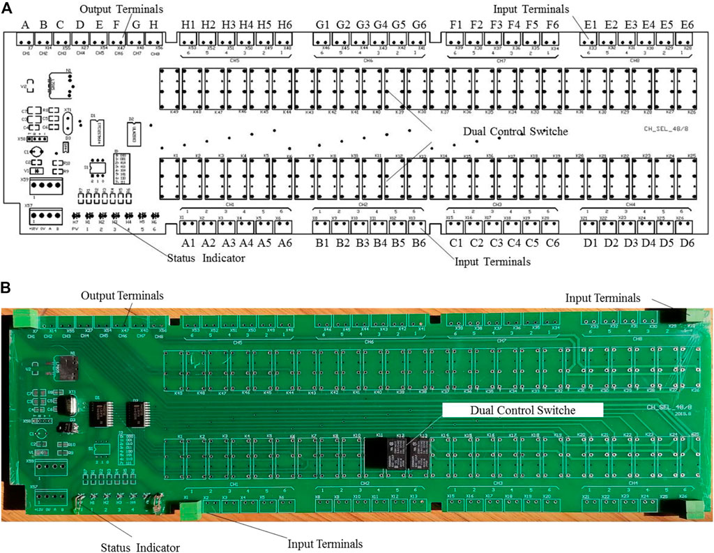
FIGURE 4. Circuit diagram and circuit board of multi-channel selection module.
The single-chip microcomputer according to Table 1 sent out the binary signal command “000″ to indicate that A1 was turned on. At this time, the 1# pin of the eight-to-one analog switch was energized, and the power was supplied to the control site of the K1 switch of the dual-control analog switch. The K1 switch was closed to make the A1 plug in the input plug and the A plug in the output plug realize the physical connection. The other switches (K2∼K6) connected to the A plug of the output plug were not powered and in the disconnected state, which would not affect the signal of the A plug of the output plug, so that the data acquisition server could realize A1 signal collection, storage, and display of the sensor connected with the plug. Then according to the wireless remote control box, it sent out binary signal instructions 001, 010, 011, 100, and 101 in turn, which means to connect the A2, A3, A4, A5, A6 sensors plugged into the input plug, and the eight-to-one analog switch sequentially simulates the dual control. The control sites of K2, K3, K4, K5, and K6 were powered, so that the K2, K3, K4, K5, and K6 switches were closed, and the A2, A3, A4, A5, and A6 sensors inserted in the input plug were connected to the output. The signal connection of the A plug in the plug could realize the signal collection, storage, and display of all sensors connected to the A2, A3, A4, A5, and A6 plugs by using the existing data acquisition server in turn.
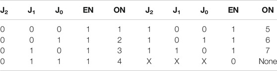
TABLE 1. Signal numbering code.
Each multi-channel selected the 1–6 switches in the controller to switch synchronously, and up to six sensors could be controlled simultaneously per signal command. For example, the input plug of A1∼A6, B1∼B6, C1∼C6, D1∼D6, E1∼E6, F1∼F6, G1∼G6, and H1∼H6 were respectively connected to the corresponding sensors. If the “000” command was issued, when the first sensor was selected to be collected, the A1, B1, C1, D1, E1, F1, G1, and H1 terminals of the input plug were powered by the K1 switch control angle of the dual-control analog switch, and connected to the output plug of A to H, thus realizing the connection of the signal. In order to clearly observe the working condition of the multi-channel selection controller, the 1# light of the light-emitting diode was always on. By analogy, if the “001” command was issued, it meant that when the second sensor was selected, the A2, B2, C2, D2, E2, F2, G2, and H2 terminals of the input plug were powered by the K2 switch control angle of the two-open and double-close analog switch. Respectively, signal connection with the A, B, C, D, E, F, G, and H plugs of the output plug was realized. At this time, the 2# light of the light-emitting diode of the multi-channel selection controller was always on.
According to the centrifugal data collection experience, six modules numbered M1∼M6 were assembled into a multi-channel selector, as shown in Figure 5. Its external dimensions were 358 mm × 291 mm × 102 mm (length × width × height), and it was a box body formed by cutting and welding a steel plate with a thickness of 1 mm. In addition, a 102 mm × 30 mm ×2 mm (length × width × thickness) angle steel with two screw holes was welded on the bottom of the left and right sides of the box to fix the instrument on the centrifuge to avoid it falling off during the rotation. Through the use of a multi-meter test, all channels on the multi-channel selector were connected and disconnected in compliance with the design requirements, indicating that this device was feasible.
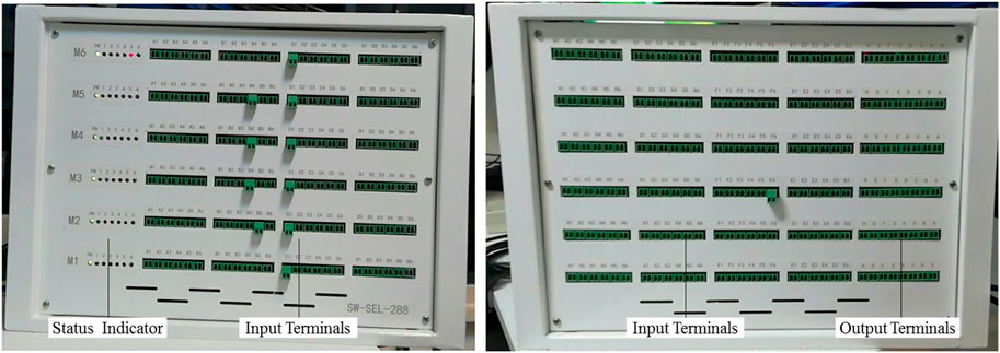
FIGURE 5. Picture of multi-channel selector.
The centrifuge test process continuously rotated around the central axis (without stopping), and the existing centrifuge cable channels had all been used up, making it impossible to control the multi-channel selector through wired methods. Therefore, a wireless method was selected for control signal transmission and reception. The operating instructions are shown in Table 2. An unloaded centrifugal test was carried out in advance, all doors and covers were closed, consistent with the centrifuge test state. The results show that the multi-channel selector operates well under the condition of 120 g centrifugation, indicating that it can be used in centrifugal tests.
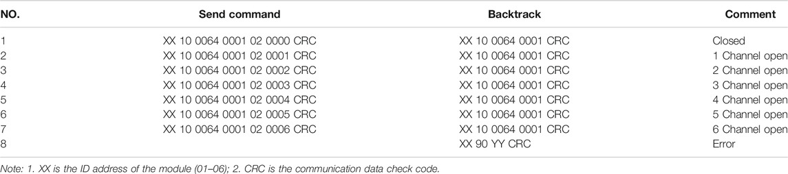
TABLE 2. Operational order.
To test the influence of the multi-channel selector on the voltage and electron signals, five kinds of voltage signals (1, 2, 3, 4, 5 V) and five kinds of electron signals (4, 8, 12, 16, 20 mA) were collected. Figure 6 shows that no matter whether the multi-channel selector was connected or not, the collected signals were the same, indicating that the multi-channel selector had no influence on signal acquisition, or its influence could be ignored.
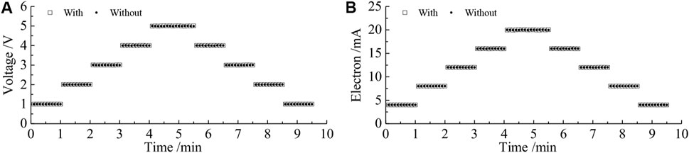
FIGURE 6. Comparison of (A) voltage and (B) electron signals with or without a multi-channel selector.
After the previous test, the multi-channel selector could be remotely controlled and connected to the line. The actual effect of it was compared through a static pressure model test.
A static pressure model of a cubic soil block was designed, in which we placed the soil block model, the loading steel plate, the dynamometer, the jack, and the measuring sensors from bottom to top in the reaction frame, as shown Figure 7. The size of the soil block was 150 mm × 150 mm × 150 mm, which was compacted layer by layer by means of tamping. The front and back sides and top of the soil block model were used to place the frame beam model and the loading steel plate, and the rest were restrained by a U-shaped steel plate to limit the deformation of the soil block.
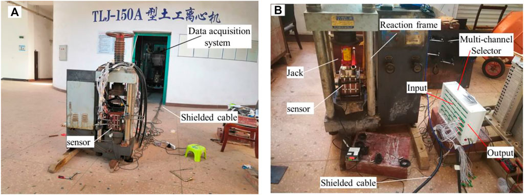
FIGURE 7. Cable connection diagram for the static pressure model test.
In order to obtain the actual use effect of the multi-channel selector, many sensors were installed in the model test. The detailed installation was as follows:
The nine axial force sensors (voltage sensor) were buried inside the soil block.
The three earth pressure sensors (voltage sensor) were loaded between the steel plate and soil block, soil block and U-shaped plate.
The six laser displacement sensors (electron sensor) were used to measure the deformation of frame beams, longitudinal beams, and soil blocks.
A total of 144 strain gauges (strain sensor) were pasted on the frame beam model.
After the model was made and the sensors were installed, the cables of all sensors were inserted into the input end of the multi-channel selector, and the output end was connected to the data acquisition system. The actual effect of the cable connection is shown in Figure 7.
The twelve voltage channels, six electron current channels, and sixteen strain channels of the data acquisition system were collected from the soil pressure sensors, axial force sensors, displacement sensors, and strain sensors on the unloaded and loaded plates, as shown in Figure 8. A total of 162 sets of data were obtained.
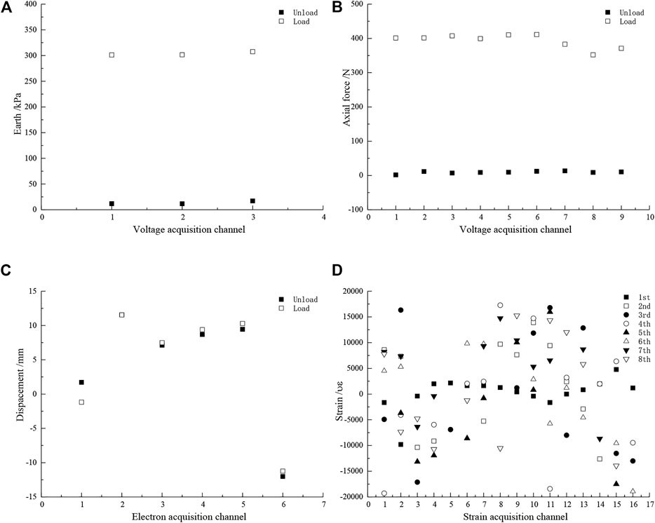
FIGURE 8. Data of static pressure model test: (A) earth pressure, (B) axial force, (C) displacement, and (D) strain.
Figure 8A displays the result of the earth pressure data. It shows that the earth pressure after loading increased to 300 kPa, which is consistent with the load applied by the loaded steel plate. Similarly, the axial force meters in nine groups of soil bodies were obtained, and the average value of the axial force loaded was 400 N in Figure 8B . In addition, the laser displacement data were within the range of −15–15 mm in Figure 8C, and the measured value was consistent with the display of the sensor. The displacement change before and after loading was relatively small, and its value was 1–2 mm. The focus of this model test was the collection of the strain data. The data of 144 strain gauges were collected in nine groups, as shown in Figure 8D. Its strain value was −20,000 με to 20,000 με, which corresponds to the change in resistance value measured by a multi-meter.
Through the static pressure model test, it was found that when the multi-channel selector works normally it is easy to operate, and connects quickly. It only takes 1–2 s to switch once using the multi-channel selector, and it takes 30 s to 1 min to select manual operation for this step. The installation of the multi-channel selector and the sensor and data acquisition system can break through the limit of the number of centrifuge acquisition channels and achieve more sensor data acquisition tasks. Another new discovery is that the multi-channel selector can also be used for data collection in conventional model tests, which can effectively shorten the time for manually disassembling the cable between the sensor and the collector.
Although the multi-channel acquisition instrument had been well applied in the static pressure model test, its purpose was to expand the data acquisition channel of the existing centrifuge, so it needed to be applied in the centrifuge model test.
The purpose was to test the application effect of the multi-channel selector through the centrifugal model test of reinforced cut slopes by anchoring frame beams. The original slope ratio was 1:2, and the first level adopted anti-slide piles with a height of 10 m; the second level slope was supported by anchor cable frame beams with a slope height of 8 m and a slope ratio of 1:1. The surface layer of the slope was red clay with a thickness of 11–18 m. The frame beam was a reinforced concrete structure with a size of 0.6 × 0.6 m (width × height). The spacing between its strings and beams was 3 m, and the length was 9 m as a unit.
Combining various constraints, the scale of this centrifugal model was n = 70. The slope model and anchoring frame beam were designed, manufactured, and installed according to Figure 9. The model was embedded with 27 axial forces (voltage sensor), 10 earth pressures (voltage sensor), six laser displacements (electron sensor), and 144 strain gauges (strain sensor). And a total of 187 sets of data needed to be collected.
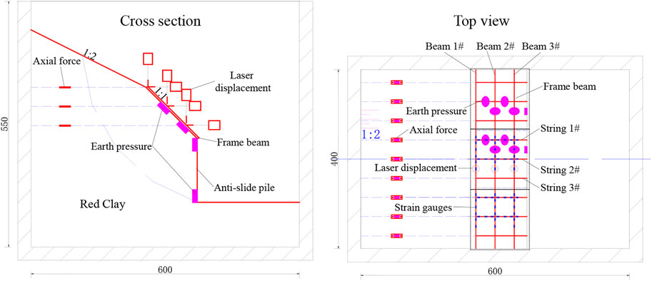
FIGURE 9. Design drawing of the centrifugal model test.
Although the data acquisition system was configured with 64 channels, each channel could only collect the sensor signal of the corresponding signal category, not any signal. For example, if an electron current sensor or strain sensor was plugged into a voltage channel, the signal data obtained was wrong. According to the number and type of sensors, the number of times to collect data of axial force, earth pressure, displacement, and strain was three, one, one, and nine, respectively. In order to obtain all sensor data, it was determined that the maximum number of data collection was nine. The number of sensors and the group collection scheme are shown in Table 3. Therefore, the signals of 187 sensors were connected to the data acquisition system through a multi-channel selector. The model making, sensor installation, and cable connection are shown in Figure 10.
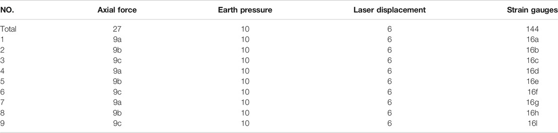
TABLE 3. Number of sensors and grouping acquisition scheme.
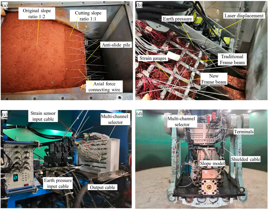
FIGURE 10. Process photos of the centrifugal model test: (A) slope forming and axial installation; (B) frame beam and sensor installation; (C) connection of various cables and multi-channel acquisition instrument; (D) all cable connection renderings.
When the centrifuge rotated to the target acceleration of 70 g, the sensor signal data were collected according to the above-mentioned collection scheme. As the laser displacement gauge exceeded the measurement range and some strain gauges were disconnected, the data for 21 axial forces, 10 earth pressures, and 103 strain gauges were obtained. Figure 11 shows the moment of the frame beam, the earth pressure at the bottom of the beam, and the axial force of the anchor cable.
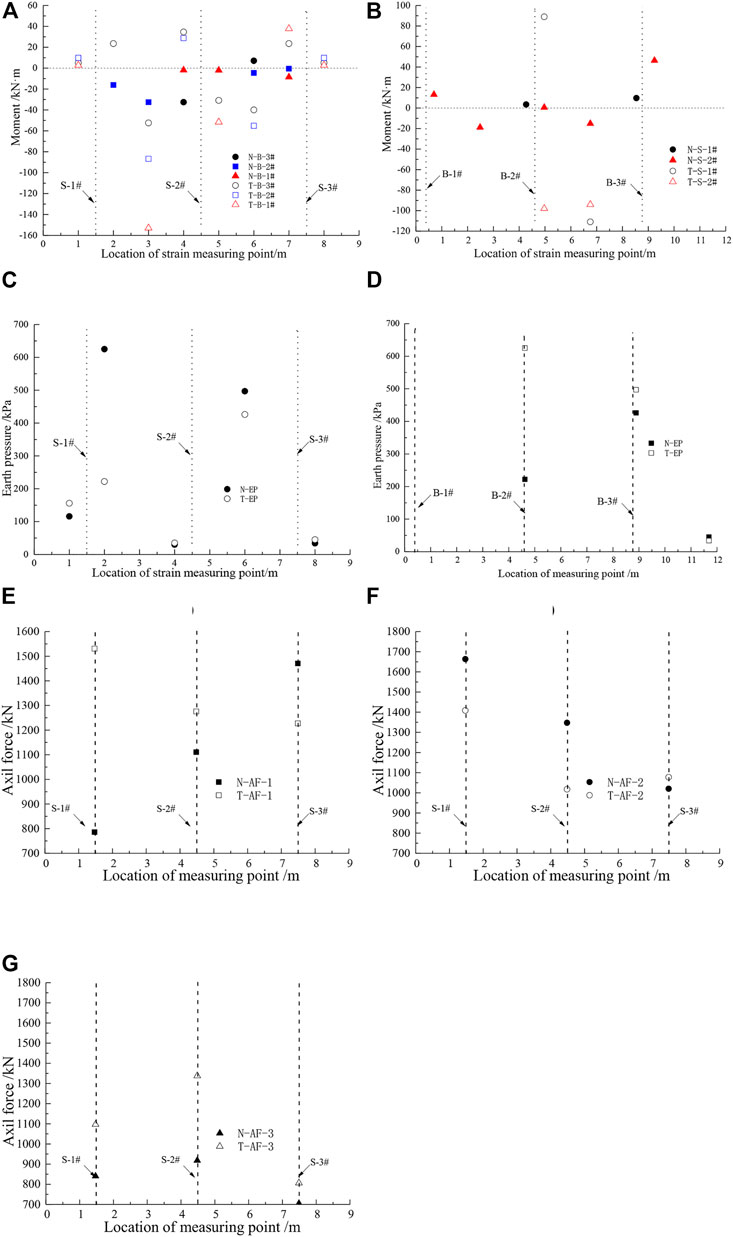
FIGURE 11. Moment of frame beam: (A) beams, (B) strings; earth pressure: the bottom of the (C) beam, (D) string and axial force of the anchor cable: (E) 1#, (F) 2#; (G) 3#.
The results of the centrifugal test model for the moment of the frame beams in Figures 11A,B show that the moment in the length direction of the entire beam cannot be described intuitively and accurately, due to varying degrees of damage and abnormality at the measuring points on the beams in the test. However, the strain gauges on the frame beams are arranged symmetrically, and the distribution of the moment along the length of the beam can be described intuitively and accurately based on the existing test results of the measuring points. Beam 1# between the two adjacent anchor cables, that is, the beam at the mid-span section of the beam body is subjected to a greater negative moment than beams 2# and 3#, which is expressed as beam 1#> 2#> 3#. The moment of the frame beams gradually decreases along with the increase in the height of the slope, that is, the top of the frame beam is the smallest and the bottom is the largest. In the moments of the transverse and longitudinal beam sections of the hinged fabricated anchor cable frame beams and the moments of the transverse and longitudinal beam sections of the traditional frame beams, it is found that the positive and negative moments on each section of the traditional frame beams are greater than those of the hinged fabricated anchor cable frame beams. It means that the new structure can use smaller size or reinforcement to achieve the same supporting effect as the traditional structure.
Similarly, Figures 11C,D are the results of the distribution of the bottom soil pressure data of the hinged-type fabricated anchor cable frame beam and the traditional frame beam cross beam and longitudinal beam. It can be seen from Figure 11C that at the same horizontal longitudinal beam position, the soil pressure in the middle section of the beam is expressed as: the soil pressure at the bottom of the traditional frame beam is greater than the bottom soil pressure of the hinged-type fabricated anchor frame beam, and the soil pressure is located in the upper middle of the frame beam longitudinal beam. The pressure is greater than the bottom soil pressure in the middle span of the frame beam longitudinal beam. The soil pressure at the bottom of the beam at the mid-span section of the same horizontal beam is greater than that of the traditional structure. In addition, because there are fewer earth pressure gauges arranged, the data obtained are more discrete, and it is difficult to concretely and accurately reflect the influence of the frame beams on the distribution of earth pressure at the bottom of the beam when the two frame beams support slopes.
The comparison diagram of the axial force of the two structures is shown in Figures 11E–G. From the overall trend, it can be concluded that the axial force of the anchor cable of the traditional structure is greater than that of the new structure. The main performance is: beam 1#> beam 2#> beam 3#, that is, the axial force of the anchor cable on the frame beam shows a non-linear decrease along the slope height, with the smallest slope at the top and the largest at the bottom. This is slightly different from the uniform or simple linear distribution of the anchor cable axial force assumed in the design of the frame beam. The actual situation encountered during the centrifugal model test must be considered, especially the difference between the left and right anchor cable axial force changes. It may be caused by the boundary effect. On the other hand, during the centrifugal model test, the structural characteristics of the frame beam, the degree of compaction, the flatness of the slope, the frame beam material, and the specifications of the axial force sensor will have a greater impact on the accuracy of the test data.
The existing centrifugal data acquisition system had a limited number of channels, and it was impossible to collect test data exceeding the number of channels in a centrifugal model test of an anchoring slope by frame beam. In view of the above shortcomings, the multi-channel selector was proposed, and it was debugged in the centrifugal no-load pre-test, and it was applied in the static pressure model and centrifugal model test. The main findings of this study are summarized as follows.
1) A multi-channel selection module is processed and manufactured through principle design, purchase of components and processing circuit boards, and assembled into a multi-channel selector. It can transform the existing “one-to-one” collection mode into “one-to-many”.
2) In the no-load test of different centrifugal fields of 1–120 g, the multi-channel selector operates stably, and realizes good wireless connection and communication with the remote controller.
3) In the static pressure model test, various sensors were connected to a multi-channel selector and then connected to a data acquisition system. The signals of 162 sensors were collected, stored, and displayed.
4) The multi-channel selector was successful in a 70 g centrifugal model test of an anchoring slope by frame beam. Only 51 channels were used to effectively obtain the signals of 187 sensors. And after the comparative analysis of the measured data, it is concluded that the force of the new structure is better than the traditional structure.
The original contributions presented in the study are included in the article/Supplementary Material, further inquiries can be directed to the corresponding author.
All authors listed have made a substantial, direct, and intellectual contribution to the work and approved it for publication.
National Natural Science Foundation of China (52025085, 51927814, 51878078, 51908070), Training Program for High-level Technical Personnel in Transportation Industry (2018-025), Design Theory, Method and Demonstration of Durability Asphalt Pavement on Heavy-duty Traffic Conditions in Shanghai Area (CTKY-PTRC-2018-003), Science and Technology Innovation Program of Hunan Province (2020RC4048), and the Hunan Provincial Innovation Foundation for Postgraduate (CX 2018B527).
Author JZ and HW were employed by Changsha University of Science and Technology in 2017 to 2020. They declare that the research was conducted in the absence of any commercial or financial relationships.
The remaining authors declare that the research was conducted in the absence of any commercial or financial relationships that could be construed as a potential conflict of interest.
All claims expressed in this article are solely those of the authors and do not necessarily represent those of their affiliated organizations, or those of the publisher, the editors and the reviewers. Any product that may be evaluated in this article, or claim that may be made by its manufacturer, is not guaranteed or endorsed by the publisher.
Amato, G., Eisank, C., Castro-Camilo, D., and Lombardo, L. (2019). Accounting for Covariate Distributions in Slope-Unit-Based Landslide Susceptibility Models. A Case Study in the alpine Environment. Eng. Geology. 260, 105237. doi:10.1016/j.enggeo.2019.105237
Broekman, A., Willem Jacobsz, S., Louw, H., Kearsley, E., Gaspar, T., and Da Silva Burke, T. S. (2020). Fly-by-Pi: Open Source Closed-Loop Control for Geotechnical Centrifuge Testing Applications. HardwareX 8, e00151. doi:10.1016/j.ohx.2020.e00151
Cao, D.-F., Shi, B., Zhu, H.-H., Inyang, H. I., Wei, G.-Q., and Duan, C.-Z. (2018). A Soil Moisture Estimation Method Using Actively Heated Fiber Bragg Grating Sensors. Eng. Geology. 242, 142–149. doi:10.1016/j.enggeo.2018.05.024
Carlà, T., Tofani, V., Lombardi, L., Raspini, F., Bianchini, S., Bertolo, D., et al. (2019). Combination of GNSS, Satellite InSAR, and GBInSAR Remote Sensing Monitoring to Improve the Understanding of a Large Landslide in High alpine Environment. Geomorphology 335, 62–75. doi:10.1016/j.geomorph.2019.03.014
Chen, R., Yin, X., Tang, L., and Chen, Y. (2018). Centrifugal Model Tests on Face Failure of Earth Pressure Balance Shield Induced by Steady State Seepage in Saturated sandy silt Ground. Tunnelling Underground Space Technol. 81, 315–325. doi:10.1016/j.tust.2018.06.031
Chortis, G., Askarinejad, A., Prendergast, L. J., Li, Q., and Gavin, K. (2020). Influence of Scour Depth and Type on P-Y Curves for Monopiles in Sand under Monotonic Lateral Loading in a Geotechnical Centrifuge. Ocean Eng. 197, 106838. doi:10.1016/j.oceaneng.2019.106838
El Sawwaf, M., and Nazir, A. (2006). The Effect of Soil Reinforcement on Pullout Resistance of an Existing Vertical Anchor Plate in Sand. Comput. Geotechnics 33, 167–176. doi:10.1016/j.compgeo.2006.04.001
Ge, S., Zu-yu, C., Yuan, L., Ming-shou, Z., and Jian-yu, W. (2017). Experimental and Numerical Investigation of the Centrifugal Model for Underwater Explosion Shock Wave and Bubble Pulsation. Ocean Eng. 142, 523–531. doi:10.1016/j.oceaneng.2017.04.035
Ghandil, M., Behnamfar, F., and Vafaeian, M. (2016). Dynamic Responses of Structure-Soil-Structure Systems with an Extension of the Equivalent Linear Soil Modeling. Soil Dyn. Earthquake Eng. 80, 149–162. doi:10.1016/j.soildyn.2015.10.014
Gourc, J. P., Camp, S., Viswanadham, B. V. S., and Rajesh, S. (2010). Deformation Behavior of clay Cap Barriers of Hazardous Waste Containment Systems: Full-Scale and Centrifuge Tests. Geotextiles and Geomembranes 28, 281–291. doi:10.1016/j.geotexmem.2009.09.014
Herbert, D. M., Gardner, D. R., Harbottle, M., Thomas, J., and Hughes, T. G. (2011). The Development of a New Method for Testing the Lateral Load Capacity of Small-Scale Masonry walls Using a Centrifuge and Digital Image Correlation. Construction Building Mater. 25, 4465–4476. doi:10.1016/j.conbuildmat.2011.02.002
Hongze, Z., Dongyu, W., Ming, M., and Kaihui, Z. (2020). Parameter Inversion and Location Determination of Evolutionary Weak Layer for Open-Pit Mine Slope. Int. J. Coal Sci. Technol. 7, 714–724. doi:10.1007/s40789-020-00337-w
Kreczmer, K., Dąbski, M., and Zmarz, A. (2021). Terrestrial Signature of a Recently-Tidewater Glacier and Adjacent Periglaciation, Windy Glacier (South Shetland Islands, Antarctic). Front. Earth Sci. 9. doi:10.3389/feart.2021.671985
Kuang, K. S. C., Tan, C. Y., Chew, S. H., and Quek, S. T. (2011). Monitoring of Large Strains in Submerged Geotextile Tubes Using Plastic Optical Fibre Sensors. Sensors Actuators A: Phys. 167, 338–346. doi:10.1016/j.sna.2011.03.013
Kutter, B. L., Carey, T. J., Hashimoto, T., Zeghal, M., Abdoun, T., Kokkali, P., et al. (2018). LEAP-GWU-2015 Experiment Specifications, Results, and Comparisons. Soil Dyn. Earthquake Eng. 113, 616–628. doi:10.1016/j.soildyn.2017.05.018
Li, J., Wang, X., Guo, Y., and Yu, X. (2019). Vertical Bearing Capacity of the Pile Foundation with Restriction Plate via Centrifuge Modelling. Ocean Eng. 181, 109–120. doi:10.1016/j.oceaneng.2019.04.026
Lin, Y.-L., Li, Y.-X., Yang, G.-L., and Li, Y. (2017). Experimental and Numerical Study on the Seismic Behavior of Anchoring Frame Beam Supporting Soil Slope on Rock Mass. Soil Dyn. Earthquake Eng. 98, 12–23. doi:10.1016/j.soildyn.2017.04.008
Lin, Y.-L., Cheng, X.-M., Yang, G.-L., and Li, Y. (2018). Seismic Response of a Sheet-Pile Wall with Anchoring Frame Beam by Numerical Simulation and Shaking Table Test. Soil Dyn. Earthquake Eng. 115, 352–364. doi:10.1016/j.soildyn.2018.07.028
Liu, H., Wang, X., and Song, E. (2011). Reinforcement Load and Deformation Mode of Geosynthetic-Reinforced Soil Walls Subject to Seismic Loading during Service Life. Geotextiles and Geomembranes 29, 1–16. doi:10.1016/j.geotexmem.2010.06.003
Ng, C. W. W., Li, X. S., Van Laak, P. A., and Hou, D. Y. J. (2004). Centrifuge Modeling of Loose Fill Embankment Subjected to Uni-Axial and Bi-Axial Earthquakes. Soil Dyn. Earthquake Eng. 24, 305–318. doi:10.1016/j.soildyn.2003.12.002
Pan, W., Pan, W., Luo, J., Fan, L., Li, S., and Erdenebileg, U. (2020). Slope Stability of Increasing Height and Expanding Capacity of South Dumping Site of Hesgoula Coal Mine: A Case Study. Int. J. Coal Sci. Technol. 8, 427–440. doi:10.1007/s40789-020-00335-y
Rotta Loria, A. F., Gunawan, A., Shi, C., Laloui, L., and Ng, C. W. W. (2015). Numerical Modelling of Energy Piles in Saturated Sand Subjected to Thermo-Mechanical Loads. Geomechanics Energ. Environ. 1, 1–15. doi:10.1016/j.gete.2015.03.002
Sabagh, M., and Ghalandarzadeh, A. (2020). Centrifugal Modeling of Continuous Shallow Tunnels at Active Normal Faults Intersection. Transportation Geotechnics 22, 100325. doi:10.1016/j.trgeo.2020.100325
Sahare, A., Tanaka, Y., and Ueda, K. (2020). Numerical Study on the Effect of Rotation Radius of Geotechnical Centrifuge on the Dynamic Behavior of Liquefiable Sloping Ground. Soil Dyn. Earthquake Eng. 138, 106339. doi:10.1016/j.soildyn.2020.106339
Shen, C., Bo, J., Qi, W., Zhang, X., Huang, J., and Qiao, F. (2020). Analysis of the Surface Rupture Process of Strong Earthquakes Based on Centrifuge Tests. Soil Dyn. Earthquake Eng. 136, 106239. doi:10.1016/j.soildyn.2020.106239
Shi, K., Wu, X., Liu, Z., and Dai, S. (2019). Coupled Calculation Model for Anchoring Force Loss in a Slope Reinforced by a Frame Beam and Anchor Cables. Eng. Geology. 260, 105245. doi:10.1016/j.enggeo.2019.105245
Thusyanthan, N. I., Madabhushi, S. P. G., and Singh, S. (2007). Tension in Geomembranes on Landfill Slopes Under Static and Earthquake Loading-Centrifuge Study. Geotextiles and Geomembranes 25, 78–95. doi:10.1016/j.geotexmem.2006.07.002
Ueda, K., Sawada, K., Wada, T., Tobita, T., and Iai, S. (2019). Applicability of the Generalized Scaling Law to a Pile-Inclined Ground System Subject to Liquefaction-Induced Lateral Spreading. Soils and Foundations 59, 1260–1279. doi:10.1016/j.sandf.2019.05.005
Viswanadham, B. V. S., and König, D. (2009). Centrifuge Modeling of Geotextile-Reinforced Slopes Subjected to Differential Settlements. Geotextiles and Geomembranes 27, 77–88. doi:10.1016/j.geotexmem.2008.09.008
Wang, X., Zeng, X., and Li, J. (2019). Vertical Performance of Suction Bucket Foundation for Offshore Wind Turbines in Sand. Ocean Eng. 180, 40–48. doi:10.1016/j.oceaneng.2019.03.049
Wang, Z.-F., Shen, S.-L., Modoni, G., and Zhou, A. (2020). Excess Pore Water Pressure Caused by the Installation of Jet Grouting Columns in clay. Comput. Geotechnics 125, 103667. doi:10.1016/j.compgeo.2020.103667
Weng, X., Sun, Y., Yan, B., Niu, H., Lin, R., and Zhou, S. (2020). Centrifuge Testing and Numerical Modeling of Tunnel Face Stability Considering Longitudinal Slope Angle and Steady State Seepage in Soft Clay. Tunnelling Underground Space Technol. 101, 103406. doi:10.1016/j.tust.2020.103406
Yang, X., Zeng, X., Wang, X., Berrila, J., and Li, X. (2019). Performance and Bearing Behavior of Monopile-Friction Wheel Foundations under Lateral-Moment Loading for Offshore Wind Turbines. Ocean Eng. 184, 159–172. doi:10.1016/j.oceaneng.2019.05.043
Yao, Y., Ni, J., and Li, J. (2021). Stress-dependent Water Retention of Granite Residual Soil and its Implications for Ground Settlement. Comput. Geotechnics 129, 103835. doi:10.1016/j.compgeo.2020.103835
Zeghal, M., Goswami, N., Kutter, B. L., Manzari, M. T., Abdoun, T., Arduino, P., et al. (2018). Stress-strain Response of the LEAP-2015 Centrifuge Tests and Numerical Predictions. Soil Dyn. Earthquake Eng. 113, 804–818. doi:10.1016/j.soildyn.2017.10.014
Zhang, J., Li, F., Zeng, L., Peng, J., and Li, J. (2020a). Numerical Simulation of the Moisture Migration of Unsaturated clay Embankments in Southern China Considering Stress State. Bull. Eng. Geol. Environ. 80, 11–24. doi:10.1007/s10064-020-01916-6
Zhang, J., Peng, J., Zhang, A., and Li, J. (2020b). Prediction of Permanent Deformation for Subgrade Soils Under Traffic Loading in Southern China. Int. J. Pavement Eng., 1–10. doi:10.1080/10298436.2020.1765244
Zhang, J., Zhang, A., Huang, C., Yu, H., and Zhou, C. (2021). Characterising the Resilient Behaviour of Pavement Subgrade with Construction and Demolition Waste under Freeze-Thaw Cycles. J. Clean. Prod. 300, 126702. doi:10.1016/j.jclepro.2021.126702
Zhang, S., Ronald, P., and Zhang, J. (2021). Three-dimensional frequency-domain Green’s functions of a finite fluid-saturated soil layer underlain by rigid bedrock to interior loadings. Int. J. Geomech. doi:10.1061/(ASCE)GM.1943-5622.0002235
Zheng, Y., Chen, C., Liu, T., Zhang, H., Xia, K., and Liu, F. (2018). Study on the Mechanisms of Flexural Toppling Failure in Anti-inclined Rock Slopes Using Numerical and Limit Equilibrium Models. Eng. Geology. 237, 116–128. doi:10.1016/j.enggeo.2018.02.006
Zheng, Y., Chen, C., Liu, T., and Ren, Z. (2021a). A New Method of Assessing the Stability of Anti-Dip Bedding Rock Slopes Subjected to Earthquake. Bull. Eng. Geol. Environ. 80, 3693–3710. doi:10.1007/s10064-021-02188-4
Zheng, Y., Wang, R., Chen, C., Sun, C., Ren, Z., and Zhang, W. (2021b). Dynamic Analysis of Anti-Dip Bedding Rock Slopes Reinforced by Pre-stressed Cables Using Discrete Element Method. Eng. Anal. Boundary Elem. 130, 79–93. doi:10.1016/j.enganabound.2021.05.014
Keywords: multi-channel selector, data acquisition system, centrifuge model test, anchoring slope, frame beam
Citation: Zhang J, Li F, Zhang S, Zhou J and Wu H (2021) Research on Application of Multi-Channel Selector in Centrifugal Model Test of Anchoring Slope by Frame Beam. Front. Earth Sci. 9:757724. doi: 10.3389/feart.2021.757724
Received: 12 August 2021; Accepted: 06 September 2021;
Published: 20 September 2021.
Edited by:
Yun Zheng, Institute of Rock and Soil Mechanics (CAS), ChinaReviewed by:
Zhi-feng Wang, Chang’an University, ChinaCopyright © 2021 Zhang, Li, Zhang, Zhou and Wu. This is an open-access article distributed under the terms of the Creative Commons Attribution License (CC BY). The use, distribution or reproduction in other forums is permitted, provided the original author(s) and the copyright owner(s) are credited and that the original publication in this journal is cited, in accordance with accepted academic practice. No use, distribution or reproduction is permitted which does not comply with these terms.
*Correspondence: Shiping Zhang, emhhbmdzaGlwaW5nd3lAMTI2LmNvbSYjeDAyMDBhOw==
Disclaimer: All claims expressed in this article are solely those of the authors and do not necessarily represent those of their affiliated organizations, or those of the publisher, the editors and the reviewers. Any product that may be evaluated in this article or claim that may be made by its manufacturer is not guaranteed or endorsed by the publisher.
Research integrity at Frontiers
Learn more about the work of our research integrity team to safeguard the quality of each article we publish.