
95% of researchers rate our articles as excellent or good
Learn more about the work of our research integrity team to safeguard the quality of each article we publish.
Find out more
ORIGINAL RESEARCH article
Front. Earth Sci. , 20 September 2021
Sec. Sedimentology, Stratigraphy and Diagenesis
Volume 9 - 2021 | https://doi.org/10.3389/feart.2021.737932
This article is part of the Research Topic Source or Sink? Erosional and Depositional Signatures of Tectonic Activity in Deep-Sea Sedimentary Systems View all 15 articles
Scours, and scour fields, are common features on the modern seafloor of deep-marine systems, particularly downstream of submarine channels, and in channel-lobe-transition-zones. High-resolution images of the seafloor have improved the documentation of the large scale, coalescence, and distribution of these scours in deep-marine systems. However, their scale and high aspect ratio mean they can be challenging to identify in outcrop. Here, we document a large-scale, composite erosion surface from the exhumed deep-marine stratigraphy of Unit 5 from the Permian Karoo Basin succession in South Africa, which is interpreted to be present at the end of a submarine channel. This study utilizes 24 sedimentary logs, 2 cored boreholes, and extensive palaeocurrent and thickness data across a 126 km2 study area. Sedimentary facies analysis, thickness variations and correlation panels allowed identification of a lower heterolithic-dominated part (up to 70 m thick) and an upper sandstone-dominated part (10–40 m thick) separated by an extensive erosion surface. The lower part comprises heterolithics with abundant current and sinusoidal ripples, which due to palaeocurrents, thickness trends and adjacent depositional environments is interpreted as the aggradational lobe complex fringes. The base of the upper part comprises 2-3 medium-bedded sandstone beds interpreted as precursor lobes cut by a 3–4 km wide, 1–2 km long, and up to 28 m deep, high aspect ratio (1:100) composite scour surface. The abrupt change from heterolithics to thick-bedded sandstones marks the establishment of a new sediment delivery system, which may have been triggered by an updip channel avulsion. The composite scour and subsequent sandstone fill support a change from erosion- and bypass-dominated flows to depositional flows, which might reflect increasingly sand-rich flows as a new sediment route matured. This study provides a unique outcrop example with 3D stratigraphic control of the record of a new sediment conduit, and development and fill of a large-scale composite scour surface at a channel mouth transition zone, providing a rare insight into how scours imaged on seafloor data can be filled and preserved in the rock record.
Scours are readily recognized erosional bedforms on modern seafloor datasets in deep-marine systems (Wynn et al., 2002; Bonnel et al., 2005; Fildani et al., 2006; Macdonald et al., 2011; Maier et al., 2011, 2020; Covault et al., 2014; Carvajal et al., 2017; Droz et al., 2020) and have been imaged in many high resolution seafloor data, providing more detail about their distribution and geometry (Carvajal et al., 2017; Droz et al., 2020; Maier et al., 2020, 2018). Scours are associated with slide scars (Pickering and Hilton, 1998; Lee et al., 2004; Moscardelli et al., 2006; Dakin et al., 2013), or located in channel-lobe-transition-zones (CLTZs) (Hofstra et al., 2015; Brooks et al., 2018a), or channel mouth settings prior to channel propagation (Carvajal et al., 2017; Droz et al., 2020; Maier et al., 2020; Pohl et al., 2020, 2019). Abundant examples of interpreted ancient small-scale scour-fills include the Ross Formation, Ireland (Elliott, 2000; Lien et al., 2003; Pyles et al., 2014), the Albian Black Flysch, Spain (Vicente Bravo and Robles, 1995), the Annot sandstone, France (Morris and Normark, 2000), the Windermere Group, Canada (Terlaky et al., 2016), the Karoo Basin, South Africa (Brooks et al., 2018a), the Macigno Costiero Formation, Italy (Eggenhuisen et al., 2011; Piazza and Tinterri, 2020), and the Boso Peninsula, Japan (Ito et al., 2014). Generally, the dimensions of these exhumed scour-fills are a few metres deep and 10–100s of metres long and wide, whilst scour dimensions described from modern systems are 10s of metres deep and 100–1000s of metres long and wide (e.g. Wynn et al., 2002; Macdonald et al., 2011; Carvajal et al., 2017). Large-scale scours infilled by turbidites are rarely documented from outcrop due to the high aspect ratio of the erosion surfaces and the difficulty in distinguishing them from channel-fills (Hofstra et al., 2015).
Stratigraphically, the presence of scour-fills can provide important insights into the evolution of deep-water system as whole, as they may mark a change in slope gradient, a temporal change in the nature of the flows, or changes in sediment supply. Changes in slope gradient and loss of confinement of a turbidity current can result in rapid flow transformation and enhanced basal shearing, which results in scouring via a process called “flow relaxation” (Komar, 1971; Mutti and Normark, 1987, 1991; García and Parker, 1993; Vicente Bravo and Robles, 1995; Wynn et al., 2002; Ito, 2008; Hofstra et al., 2015; Brooks et al., 2018a; Pohl et al., 2019). The depositional or erosional nature of flows either leads to infilling of the scour or further erosion where sediments are largely bypassed and deposited further downdip (Hofstra et al., 2015; Brooks et al., 2018a). Therefore, improved identification of scour-fills, and their stratigraphic evolution, can contribute to improved understanding of source-to-sink approaches.
The deep-marine stratigraphy of Unit 5 from the Permian Karoo Basin succession in South Africa, provides a unique outcrop where a large composite erosion surface can be mapped with three dimensional constraints. The presence of the erosion surface marks a significant and abrupt change from an up to 70 m thick lower package of heterolithics to a 40 m thick package of amalgamated sandstones. Unit 5 palaeogeography has been constrained by past studies (Hodgson et al., 2006; Hofstra et al., 2017; Johnson et al., 2001; Wild et al., 2009, 2005), and with the 3D outcrop control and research borehole data the following objectives are addressed: 1) to investigate the depositional environment of the thick basal package of heterolithics; 2) to document and establish the origin of the 3D erosion surface; and 3) to propose a palaeogeographic evolution of Unit 5 in the Skoorsteenberg area.
The Karoo Basin is bounded by the southern and western branches of the Cape Fold Belt (Figure 1A), and was traditionally interpreted as a retroarc foreland basin that developed from the early Permian (e.g., (De Wit and Ransome, 1992; Veevers et al., 1994; Visser and Praekelt, 1996; Visser, 1997; López-Gamundí and Rossello, 1998). However, recent models relate Permian subsidence to long-wavelength dynamic topography driven by the subducting palaeo-Pacific plate (Tankard et al., 2009), and no emergent Cape Fold Belt at the time of deep-water deposition (Blewett and Phillips, 2016). The Tanqua and Laingsburg depocentres make up the SW part of the Karoo Basin (Figure 1A), and are filled by the Late Carboniferous to Early Jurassic Karoo Supergroup (>5 km thick). Within the Tanqua depocentre, this succession comprises the glacial Dwyka Group, overlain by the post-glacial deep-marine to shallow-marine Ecca Group, and the non-marine Beaufort Group (Figure 1B). The Ecca Group is an approximately 1.4 km thick shallowing upward succession from deep-marine to fluvial settings (King et al., 2009; Flint et al., 2011). The 0.4 km thick Skoorsteenberg Formation is part of the Ecca Group and comprises four submarine fans (Fans 1–4) and an overlying succession termed Unit 5 (Bouma and Wickens, 1994; Morris et al., 2000; Johnson et al., 2001; Hodgson et al., 2006; Wild et al., 2009), which is the focus of this study. Several field studies (Bouma and Wickens, 1991; Johnson et al., 2001; Hodgson et al., 2006; Prélat et al., 2009; Kane et al., 2017; Hansen et al., 2019) and 11 research boreholes (Luthi et al., 2006; Spychala et al., 2017a; Hofstra et al., 2017) constrain the stratigraphic framework of the Skoorsteenberg Formation.
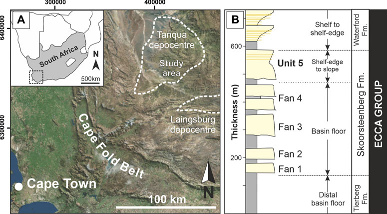
FIGURE 1. (A) The southwestern Karoo Basin with the Tanqua depocentre and the study area outlined. (B) A summary of the Ecca Group stratigraphy modified from Hodgson et al. (2006), Prélat et al. (2009).
Originally, the distal (northern) area of Unit 5, at Skoorsteenberg, was recognised as Fan 5, and interpreted as a slope fan, and the southern, most proximal area, at Groot Hangklip, was referred to as Fan 6 (Wickens 1994; Basu and Bouma, 2000; Wach et al., 2000; Johnson et al., 2001; van der Werff and Johnson, 2003). Regional mapping of an overlying 12 m thick mudstone that correlated these sand-prone units led to the redefinition of Unit 5 (Wild et al., 2009).
In proximal (southern) areas of Unit 5 at Kleine Hangklip, stacked W-E and SW-NE orientated submarine slope channel complexes have been interpreted (Wild et al., 2005; Bell et al., 2020) that overlie the updip pinchout of Fans three and 4 (Hansen et al., 2019). In distal (northern) areas of Unit 5 submarine fan deposits have been mapped southeast of the study area at Blaukop, where sand-rich channel-fills incise into proximal lobes (Hofstra et al., 2017). This study focuses on the northern exposures of Unit 5 at Skoorsteenberg that are characterised by a thick lower part (∼70 m) of thin-bedded sandstones and siltstone, and an upper part (∼40 m) of thick-bedded sandstones. Previous interpretations of these outcrops include “interfan deposits” overlain by a slump scar-fill towards the top (Johnson et al., 2001) and as an axial channel conduit (22 m thick, 8 km wide) that diverges downdip into three distributary channels (van der Werff and Johnson, 2003). Overall, published studies point towards Unit 5 being a deep-water slope apron fed by multiple W-E and SW-NE submarine channel-levees feeding lobes (Hodgson et al., 2006), with an overall younging direction of conduits along slope to the NW.
This study is based on 24 measured outcrop sections and 2 behind outcrop cores (NS1 and NS2) located to the east of the outcrop area (Figure 2A). These sections were logged at 1:50 scale (∼1 km cumulative thickness), recording grain size, sedimentary structures and bounding surfaces. Two cores and three outcrop logs cover the whole thickness of Unit 5, which is defined by underlying and overlying regional mudstones (Wild et al., 2009). Fifteen outcrop logs focus on the sandstone-prone upper part of Unit 5 (Figure 2A).
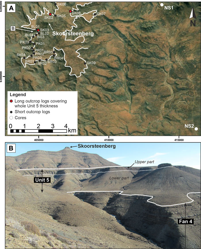
FIGURE 2. (A) A detailed map of the study area with log locations in indicated. (B) Overview photo of the study area showing Fan 4 and the partitioning seen in Unit 5.
For this study, Unit 5 is subdivided into a lower and upper part (Figure 2B) using a distinctive concretion marker bed, which was walked out in order to observe the spatial and temporal distribution of overlying sedimentary facies. Photo panels and photogrammetric models of the outcrop created from Uncrewed Aerial Vehicle (UAV) imagery (Stratigraphy Group, University of Leeds, 2021), using Agisoft Metashape and LIME, were used to document and interpret stratigraphic surfaces and architectural elements. Quantitative analysis of the thickness variations (using the inverse distance weighted (IDW) interpolation method in ESRI ArcGIS) of the whole of Unit 5, and the lower and upper parts, was undertaken to determine regional changes.
Table 1 summarizes the sedimentary facies scheme (Figure 3), determined by their lithology, sedimentary structures, bed thickness, contacts and geometries.
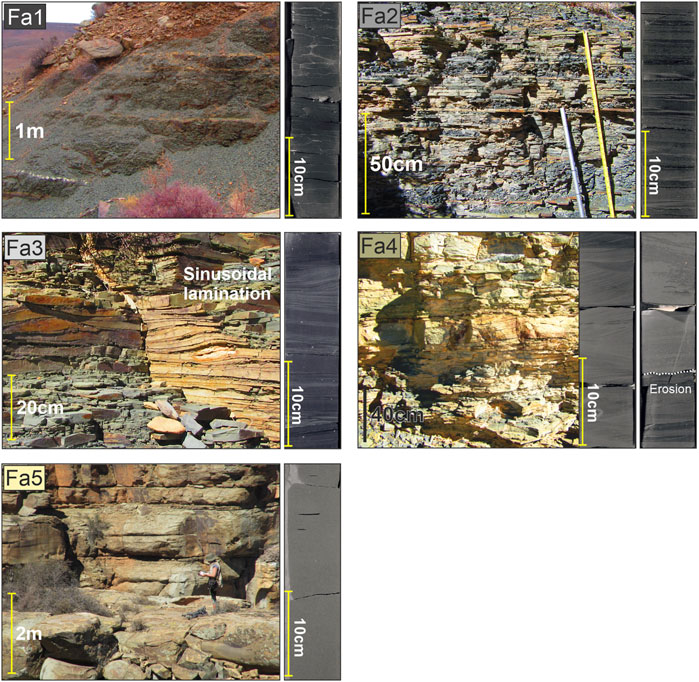
FIGURE 3. Representative photographs of the five sedimentary facies in outcrop and core: FA1- Mudstone, FA2–Siltstone-prone heterolithics, FA3–Sandstone-prone heterolithics, FA4–Thin to medium-bedded sandstone, FA5–Medium to thick-bedded sandstone.
Unit 5 has been subdivided into two parts using a distinctive concretion marker bed (5–12 cm thick) that is resistant to weathering, at a consistent stratigraphic level and was walked out across the outcrop area. The lower part is dominated by thin-bedded heterolithics, and the upper part by medium-to thick-bedded sandstone (Figure 4). We present palaeocurrent and thickness data based on these two parts. The concretion marker bed is not identified in the NS1 and NS2 cores, which means the thickness of the lower and upper parts is poorly constrained.
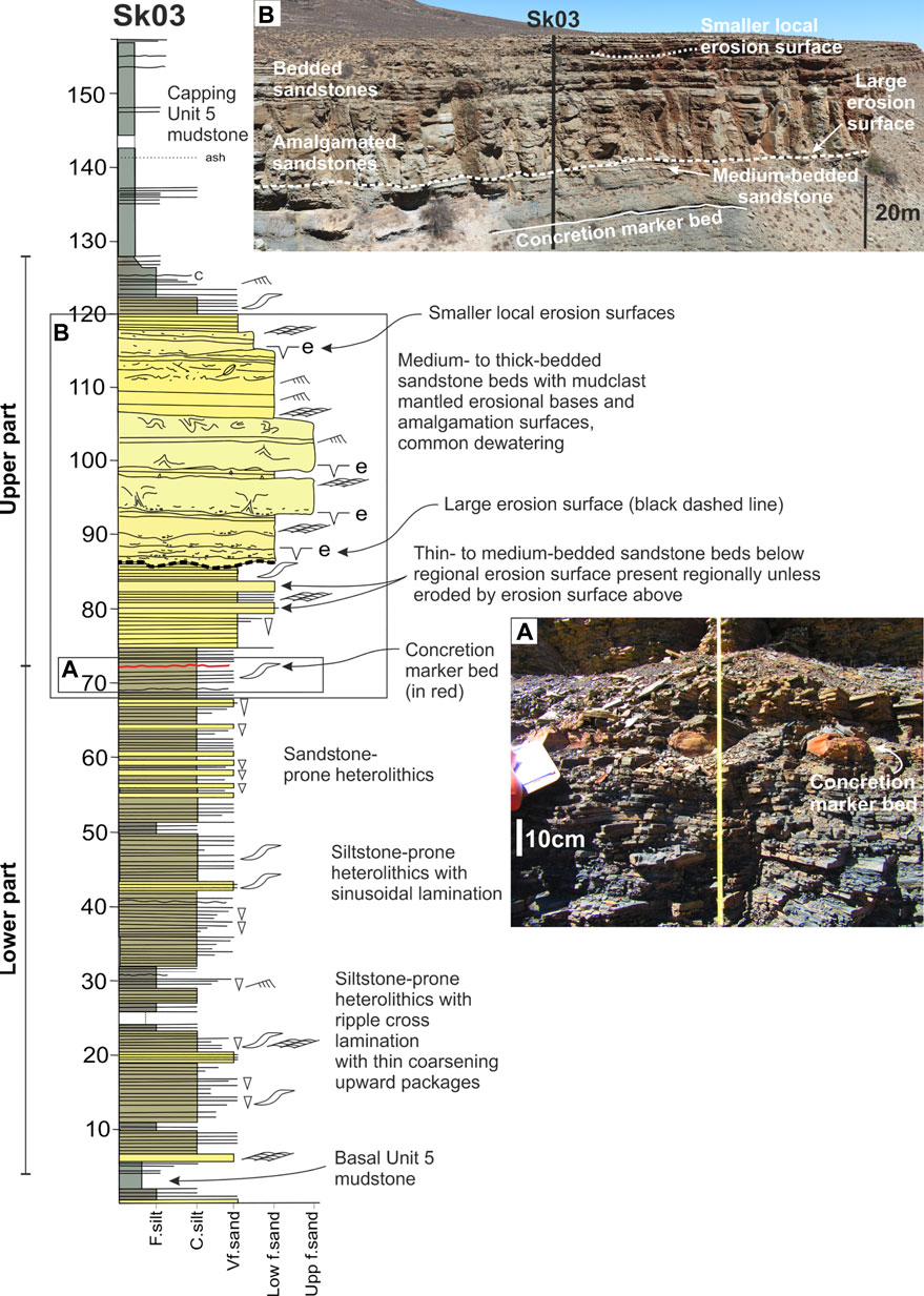
FIGURE 4. Log SK03 showing an overview of the Unit 5 stratigraphy with the lower thin-bedded and upper sandstone-prone parts. The concretion marker bed and regional erosion surface are highlighted by a red solid and black dashed line respectively. (A) Photo of the thin-bedded succession with concretion marker bed. (B) Photo of log SK03 showing the concretion marker bed and the medium-bedded sandstone beds below the regional erosion surface. The sandstone fill of the large erosion surface can be seen as well as a small erosion surface towards the top of this fill.
Four hundred and two palaeocurrent measurements were collected from current and climbing ripple lamination, groove marks, and orientation of margins of incision surfaces. The palaeocurrent data (Figures 5B,C) have a narrow spread from N to NE, which is consistent with the overall depositional dip direction for the Skoorsteenberg Fm. (e.g. Hodgson et al., 2006; Prélat et al., 2009; Hansen et al., 2019). The lower thin-bedded part is dominated by current and climbing ripple laminations trending towards the NE (average 084°, n = 207) (Figure 5B), with the upper part showing more dispersed trends to the N to NE (average 074°, n = 195) (Figure 5C).
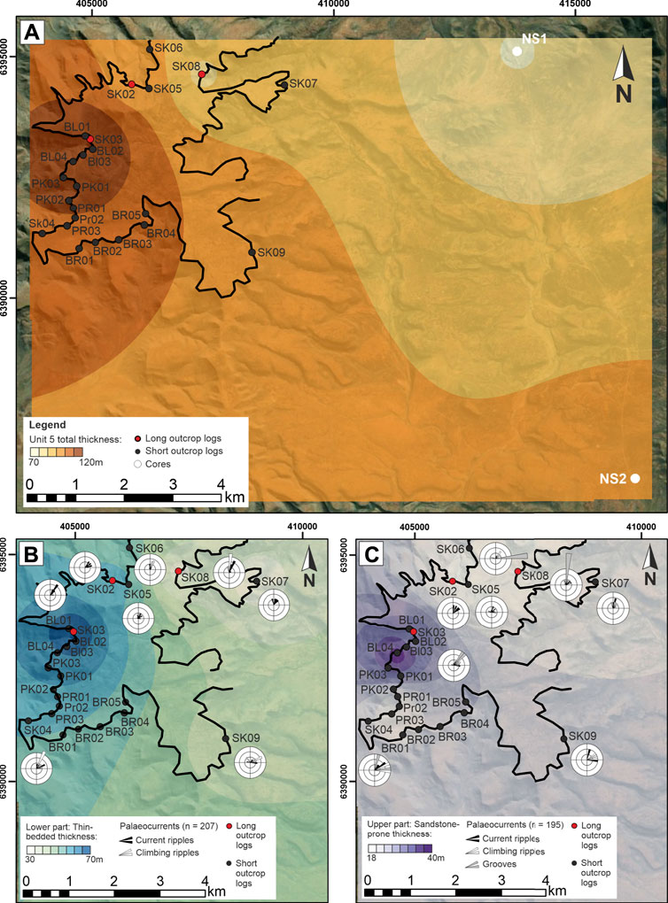
FIGURE 5. (A) Unit 5 isopach map showing thickening to the NW; (B) Isopach map of the lower thin-bedded part showing thickening towards the W, with palaeoflow to the N and NE; (C) Isopach map of the upper sandstone-prone part showing thickening towards the W, with palaeocurrents indicating flow towards the N and NE. The black line indicates the outcrop belt of the upper division of Unit 5.
The Unit 5 isopach map shows eastward thinning from 120 m in the Skoorsteenberg area to 70 m at NS1 (Figure 5A). The lower thin-bedded part is bounded by the basal mudstone below Unit 5 and the concretion marked bed at the top (Figure 4), and thickens to the NW from 33 to 68 m thick (Figure 5B). The facies above the concretion marker bed change to medium-to thick-bedded, coarser grained sandstones, which are incised by a widespread erosion surface that can be correlated between field logs for kilometres (Figure 4). Overlying this erosion surface is filled by medium-to thick-bedded sandstones that thicken westward up to 40 m (Figure 5C).
The thin-bedded lower succession overlies the basal mudstone that separates Fan 4 and Unit 5 and is characterised by siltstone- and sandstone-prone heterolithics (FA2, FA3), dominated by sinusoidal, climbing, and current ripples (Figures 4A, 6). Sinusoidal lamination is a form of highly aggradational climbing-ripple cross-lamination (Jopling and Walker, 1968), which indicate persistent high rates of sediment deposition. This suggests that sediment gravity flows were expanding and depositing rapidly, either due to a change in gradient or an abrupt change in topographic confinement (Allen, 1973; Kneller, 1995; Jobe et al., 2012). Individual beds are normally graded, and coarsening- or fining-upwards packages (<5 m thick) are identified, but thicker grain-size or thickness trends are not present. A more sandstone-prone heterolithic unit, up to 12 m thick, is present towards the top of the succession (Figures 4, 6).
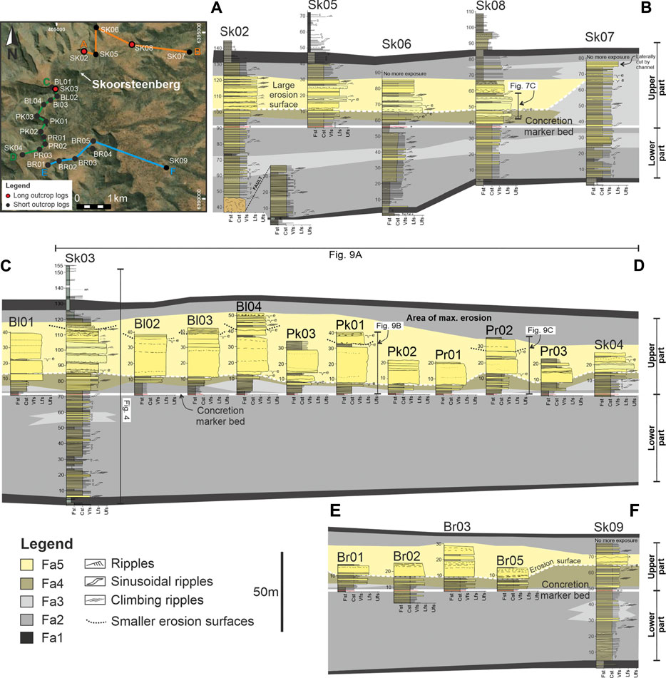
FIGURE 6. Correlation panel of outcrop logs of Unit 5 flattened on the concretion marker bed on (the white solid line). The erosion surface is marked by the white dashed line with smaller erosion surfaces in the upper part shown by the black dashed lines. Locations of correlation panels A-B, C-D and E-F are shown in the map on the top left.
The upper section of the Unit 5 stratigraphy is constrained using the concretion marker bed as a basal datum and the capping regional mudstone at the top of Unit 5 (Figures 4, 6). The concretion marker bed (5–12 cm thick) is identified by a distinctive brown-orange colour, is more resistant to weathering, and contrasts to the light grey to pale yellow of the surrounding stratigraphy (Figure 4B). The bed is laterally continuous for kms and was walked out between outcrop logs.
The stratigraphy overlying the concretion marker bed consists of ∼5 m of siltstone- and sandstone-prone heterolithics (FA2 and FA3) above which two to three medium-to thick-bedded, sandstone beds are present (Figures 4, 6, 7B–D). These are truncated by an extensive erosion surface mantled by mudclasts (Figure 7A), which can be correlated between the outcrop logs. Multiple smaller erosion surfaces merge onto the larger surface indicating its composite nature (Figure 7D). To establish the shape and amount of erosion into the underlying stratigraphy, two measurement methods were employed (Figure 8): 1) measuring the stratigraphic thickness between the concretion marker bed and the base of the erosion surface from the logs, which showed that net erosion is up to 28 m (Figure 8A), and 2) mapping the erosion surface using photogrammetric models of the outcrop built from UAV imagery to provide 3D constraints on the shape (Figures 8B–D), and the elevation change from inside to outside the cut to constrain erosion depth. The results of both methods showed that the area of maximum erosion is in the west of the study area, between logs SK03 and PK02 forming a deeper low aspect ratio heel of maximum erosion. The length of erosion is at least 1–2 km long in a downdip direction, and about 3–4 km wide in a strike section (Figure 8).
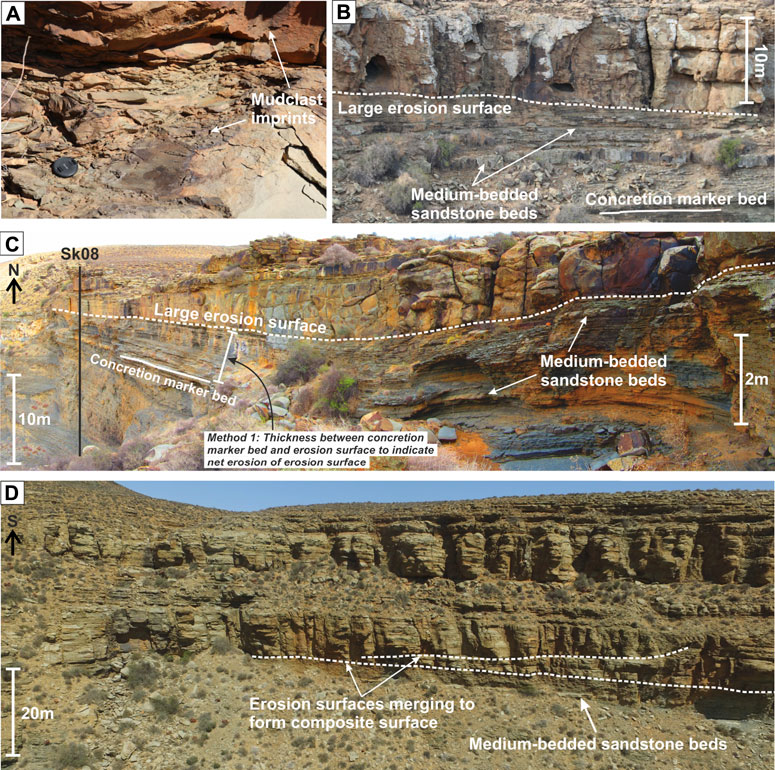
FIGURE 7. (A) Photo of erosion surface mantled with mudclasts. (B,C) Photos of stratigraphy between concretion marker bed and the erosion surface with medium-bedded sandstone beds highlighted. The location of log SK08 is shown in (C) with the part of the log shown in the photo highlighted in Figure 6. Method 1 of measuring amount of erosion by the erosion surface is explained in Figure 8. (D) Photo of the upper sandstone-prone part of the stratigraphy showing multiple erosion surfaces merging indicating the composite nature of this surface.
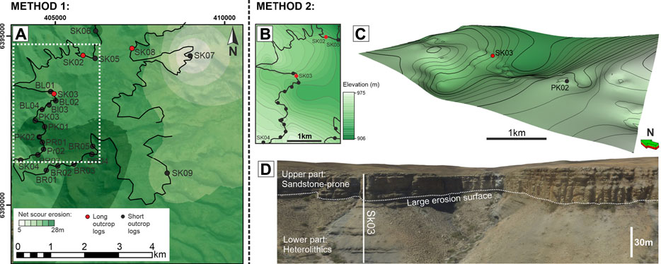
FIGURE 8. Images of the erosion surface at the base of the upper sandstone-prone part generated using two methods. (A) Method 1: Map of the erosion surface generated by measuring the thickness between the concretion marker bed and the erosion surface, which suggests up to 28 m of erosion. The white dashed box indicates the location of the map in B. (B) Method 2: Detailed map of the erosion surface generated by mapping the surface on photogrammetric models of the outcrop created from Uncrewed Aerial Vehicle imagery. This map shows relative elevation of the erosion surface within the model with darker colours indicating lower elevation and hence more erosion, and lighter colours indicating higher elevations and hence less erosion. Note that the tectonic tilt has not been removed. (C) 3D image of the erosion surface shown in (B) utilizing the same colour bar. Note the deeper and narrower updip and wider and shallower downdip form. (D) Image of the photogrammetric model of the outcrop at SK03 indicating the erosion surface that was mapped by the dashed white line.
Above the laterally extensive erosion surface, and in the area of maximum erosion, the stratigraphy is characterised by a 40 m thick succession of amalgamated, structureless to parallel laminated, thick bedded sandstones (Figures 4, 6, 9A,B). In areas overlying less erosion, the succession is more stratified and characterised by ripple laminated medium-bedded sandstones (Figures 6, 9C).
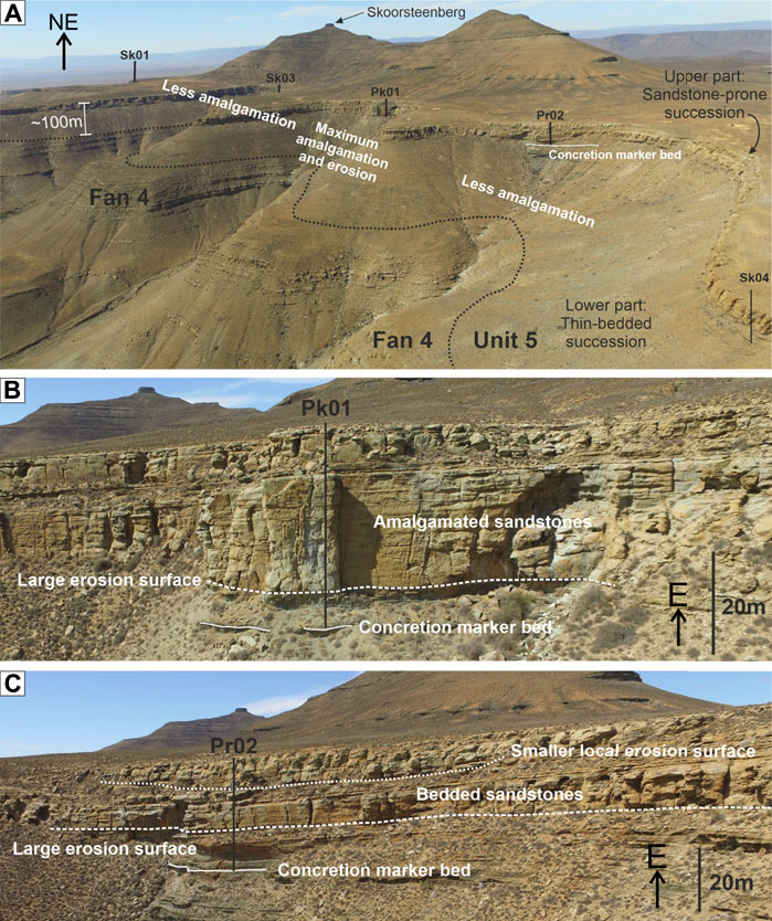
FIGURE 9. (A) Uncrewed Aerial Vehicle imagery photograph of the western side of the outcrop indicating areas of maximum amalgamation and erosion in the upper sandstone-prone part of the stratigraphy. The part of the correlation panel shown in the photo is highlighted in Figure 6. (B) Photo of the amalgamated fill of the erosion surface at log PK01 (shown in Figure 6), with location indicated in (A). (C) Photo of the bedded fill of the erosion surface at log PR02 (shown in Figure 6), with location indicated in (A). An erosion surface present higher up the stratigraphy is also highlighted.
Overlying this initial depositional phase, concave-up erosion surfaces 10–150 m wide, 1–8 m deep incise into underlying sandstones (Figures 4C, 6, 9C), and are overlain by medium-bedded structureless sandstones. Locally, the larger erosion surfaces are mantled with mudstone and siltstone clasts.
The uppermost stratigraphy of Unit 5 comprises siltstone-prone, ripple laminated heterolithics, with rare sinusoidal laminations (Figure 4). The heterolithics fine upwards to a 12–15 m thick, capping mudstone, indicating the termination of Unit 5.
In both cores, the base of Unit 5 is defined by a several metres thick mudstone (Figure 10), with the top of the boreholes sited close to the top of Unit 5. In NS1, Unit 5 is ∼72 m thick, and consists of a basal ∼25 m thick heterolithic unit, overlain by a ∼20 m thick coarser grained, structureless to ripple laminated, medium to thick-bedded sandstone unit (Figure 10). Another siltstone-prone heterolithic unit is overlain by a ∼15 m thick medium-to thick-bedded, structureless to ripple laminated sandstone package with mudclasts mantling erosion surfaces (Figure 10). Unit 5 in NS2 is ∼91 m thick, with a lower ∼30 m siltstone- and sandstone-prone heterolithic package (Figure 10). Above this a ∼25 m thick, very fine to fine-grained, medium to thick-bedded sandstone package punctuates the succession, which is predominantly parallel and ripple laminated (Figure 10). Small (<1 cm diameter) mudclasts at bed bases and truncation of beds mark erosion surfaces. Some sandstones become argillaceous towards the bed tops, suggesting the presence of hybrid beds in this succession. Another heterolithic unit is overlain by a ∼20 m thick unit of medium-to thick-bedded structureless and climbing rippled sandstones (Figure 10).
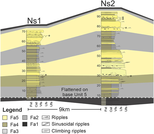
FIGURE 10. Correlation between cores NS1 and NS2 with interpreted sedimentary facies indicated. The regional extent of the two sandstone packages is unknown.
Fine-scale correlation of Unit 5 between the cores and outcrop logs is challenging in the absence of the concretion marker bed. Despite the 9 km distance between the cores, the two distinct sandstone packages may be correlated. However, their correlation with the Skoorsteenberg outcrops is uncertain. Nonetheless, the sedimentary facies observed in both cores, particularly the argillaceous sandstone beds interpreted as hybrid beds in NS2, suggest that these sandstones represent lobe complexes. Lobes have also been interpreted 7 km to the south of NS2 in the lower part of Unit 5 at Blaukop and core BK1 (Hofstra et al., 2017). These associations support the lower part of Unit 5 in the cores being lobe complexes, with more evidence for erosion in the upper sandstone package, although the facies support an interpretation of more lobe axes in a lobe complex. The thin-bedded heterolithics between share affinities (bed thickness, ripple laminated sandstones) to a similar succession in Fan 4, and support a similar interpretation as the fringe of another lobe complex (Spychala et al., 2017a).
The heterolithic succession in the lower part of Unit 5 (70 m thick) has an abundance of sinusoidal, climbing and current ripples but no major coarsening- or fining-upwards trends. Thick accumulations of thin-bedded heterolithics in deep-water settings either occur in external levees adjacent to submarine channels, as internal levees and terrace deposits within large-scale erosion surfaces, or at lateral or distal lobe fringes and basin plain settings (Walker, 1975; Normark and Piper, 1991; Skene et al., 2002; Deptuck et al., 2003; Kane et al., 2007; Kane and Hodgson, 2011; Hansen et al., 2015; Spychala et al., 2017b). Sinusoidal ripples have previously been described in the Karoo Basin, in external and internal levees and aggradational lobe fringe deposits in the Fort Brown Formation in the Laingsburg depocentre (Kane and Hodgson, 2011; Morris et al., 2014a; Spychala et al., 2017b). Previous work has constrained the palaeogeographic context of the study area where there is a downdip architectural change from submarine channel complexes 25 km south of the study area (e.g. Wild et al., 2005; Bell et al., 2020) to lobe-dominated deposits mapped southwest of Skoorsteenberg (Hofstra et al., 2017).
Thick accumulations of heterolithics, or thin-bedded turbidites, in external levee successions have been observed from many outcrops, modern seafloor studies and in the subsurface (Clemenceau et al., 2000; Kane et al., 2007; Babonneau et al., 2010; Kane and Hodgson, 2011; Maier et al., 2012, 2013; Paull et al., 2013; Morris et al., 2014a; Hansen et al., 2015). Typical characteristics include underlying frontal lobes, thinning away from an adjacent submarine channel, and an overall fining- and thinning upwards trend attributed to levee growth and increased flow confinement allowing only the upper, fine-grained parts of turbidity currents to overspill and deposit sediments (Buffington, 1952; Manley et al., 1997; Skene et al., 2002; Deptuck et al., 2003; Kane et al., 2007; Kane and Hodgson, 2011; Nakajima and Kneller, 2013; Hansen et al., 2015). In the study area, the heterolithics do not show fining-upwards trends, and whilst thinning and palaeocurrent trends can be seen towards the NE (Figure 5), no contemporaneous submarine channel system is identified to account for flow stripping and overspilling of turbidity currents. Furthermore, the heterolithic package directly overlies the capping mudstone of the underlying Fan 4 system with no thicker sandstone beds that could be interpreted as frontal lobe present, thus making an external levee origin unlikely. An internal levee or terrace deposit interpretation is not supported due to the absence of a confining erosion surface, and the consistent palaeocurrent directions.
Lobe fringes are also composed of packages of heterolithics but require certain conditions to accumulate packages of up to 70 m thick. Aggradational lobe fringes documented from the Laingsburg depocentre in the Karoo Basin, were pinned in one location by the presence of intrabasinal slopes (Spychala et al., 2017b). Aggradational onlaps form in weakly confined basins where the bounding slope angles are less than 1° (Smith, 2004; Smith and Joseph, 2004; Spychala et al., 2017b). The effects of subtle topography on sedimentary facies and depositional architectures in deep-water settings has been widely documented (Hansen et al., 2019; Pyles, 2008; Smith, 2004; Spychala et al., 2017b). The sedimentary structures in the lower part of Unit 5 indicate that the very fine-grained sandstones, sandy siltstones and siltstones with climbing and sinusoidal ripples were rapidly deposited from density stratified turbidity currents with high rates of suspended sediment load fallout. The lack of hybrid event beds within this succession supports these heterolithics being deposited in lateral rather than frontal lobe fringe settings (Hansen et al., 2019; Spychala et al., 2017a). However, the thickness of the heterolithic package is greatest in the west (Figures 5, 6), whereas if a SE-facing intrabasinal slope was present to pin the lobe fringe setting, a thinning trend would be predicted. The underlying upper Fan 4 deposits are also thickest in the Skoorsteenberg area (Spychala et al., 2017a), which initially might have formed a subtle high after deposition of the mudstone between Fan 4 and Unit 5. However, that Fan 4 and Unit 5 are thickest in the same location suggests increased subsidence rates may have affected this area during sedimentation allowing a greater thickness of thin beds to accumulate. Palaeocurrents towards the N and NE (Figure 5) indicate that turbidity currents were largely sourced from the south with the NE trend indicating that they were likely following the main downslope gradient at the time of deposition.
The prominent large-scale erosion surface that widens and shallows downdip above the heterolithic succession is within the upper sandstone-prone part of Unit 5. In deep-water settings, large scale, high aspect ratio erosional surfaces of this geometry are likely scours that vary in dimensions from 10s of metres to multiple kilometres in width and length and cm to 10s of metres in depth (Ito et al., 2014; Hofstra et al., 2015). An alternative interpretation of a high aspect ratio channels would be sub-parallel sided and not shallow downdip so prominently. Large scour surfaces can form in the headwall areas of slide scars (e.g. Pickering and Hilton, 1998; Lee et al., 2004; Moscardelli et al., 2006; Dakin et al., 2013). Alternatively, scours are commonly concentrated in channel-lobe-transition-zones (CLTZs) (Hofstra et al., 2015; Brooks et al., 2018a), in channel mouth settings (Carvajal et al., 2017; Droz et al., 2020; Maier et al., 2020; Pohl et al., 2020, 2019), or have a multi-event origin.
Large-scale erosion surfaces formed by submarine landslides are associated with downdip Mass Transport Deposits (MTDs), and have been documented in slope settings in several subsurface examples (Moscardelli et al., 2006), modern seafloor datasets (Gamberi et al., 2011; Macdonald et al., 2011), and in some outcrop examples (Pickering and Hilton, 1998; Dakin et al., 2013; Brooks et al., 2018b). The erosion surface within Unit 5 has previously been interpreted as a slump scar (Johnson et al., 2001). In the translational domain, slump scar surfaces are the basal shear surface and are overlain by debrites or slumped sediments related to the initial sediment failure. In Unit 5, the erosion surface is infilled by turbidites, which if a slump origin is advocated points to the surface being in the proximal evacuation zone. The scale of the erosion surface described here would imply a large volume mass failure, and the absence of any slumped sediment or debrite above the erosion surface or downdip makes a slump scar origin unlikely.
High-resolution bathymetric data from modern deep-water systems have revealed extensive scouring in channel mouth settings, where the confining channel surface widens and shallows (Carvajal et al., 2017; Droz et al., 2020; Maier et al., 2020), rather than forming a discrete CLTZ between well-defined channels and well-defined lobes. Scouring of channel margins is shown to be extensive especially in areas with higher slope gradients (>1°) (Carvajal et al., 2017). Coalescence of scour surfaces is likely a major driver for channel avulsion, inception and propagation resulting in further turbidity current confinement (Droz et al., 2020). In the La Jolla channel, these scours form laterally extensive erosion surfaces that can extend for kilometres downdip of the channel mouth (Maier et al., 2020). The scale and subtle relief of the scours reported from channel mouths is similar to the erosion surface seen in Unit 5. However, these scours have been shown to occur adjacent to, or within, channels. Although submarine channel complexes have been reported from updip areas, there is no evidence for a channel at this stratigraphic level in Unit 5 around Skoorsteenberg. If it is a channel mouth setting, then the channel did not propagate further into the basin.
Scouring is commonly reported from CLTZs where turbidity currents loose confinement resulting in rapid flow deformation and enhanced basal shearing of the turbidity current (Komar, 1971; Mutti and Normark, 1987, 1991; García and Parker, 1993; Vicente Bravo and Robles, 1995; Wynn et al., 2002; Ito, 2008; Hofstra et al., 2015; Brooks et al., 2018a) via a process referred to as “flow relaxation” (Pohl et al., 2019). Interpreted exhumed CLTZs are characterized by scour-fills, and thin and discontinuous structureless and structured sandstones dominated by ripple and climbing ripple lamination (García and Parker, 1993; Hofstra et al., 2015; Brooks et al., 2018a) that might be the remnants of sediment waves (Hofstra et al., 2018). Scours in CLTZs have been shown to vary in depth and dimensions, and outcrop studies from the Karoo Basin suggest that they can form individual small-scale scours, or large-scale composite scours interpreted to represent prolonged periods of weakly confined sediment bypass (Hofstra et al., 2015; Brooks et al., 2018a). The 3D exposure of the erosion surface within Unit 5 indicates a 3–4 km wide, 1–2 km long, and up to 28 m deep surface. The scale of the surface is large compared to other outcrop studies, and suggests that this is a composite scour surface in a channel mouth transition zone that originated from bypassing flows that deposited sediment further downdip, with the main scour-fill infilled by subsequent flows.
The stratigraphic evolution of Unit 5 at Skoorsteenberg (Figure 11) is based on our preferred interpretation of the depositional environment of the lower heterolithic part and the origin of the erosion surface. The basal heterolithics are interpreted as the aggradational fringes of multiple stacked lobe complexes identified towards the E and SE (Hofstra et al., 2017), with lobe complexes also interpreted in cores NS1 and NS2. The aggradational lobe complex fringes are interpreted to have formed in an area that underwent preferential subsidence during sedimentation as the isopach thicks of Unit 5 and upper Fan 4 coincide, rather than representing the infill of pre-existing topography (Figure 11A).
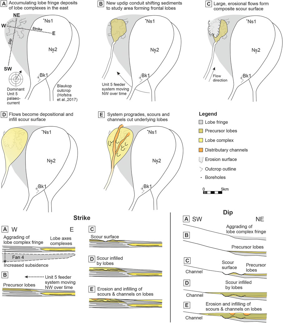
FIGURE 11. Stratigraphic evolution of Unit 5 at Skoorsteenberg shown from (A) to (E). Stacking patterns of deposits related to (A) to (E) in both strike and dip sections are also shown.
Two to three ∼0.5 m thick fine-grained sandstone beds are present above the package of heterolithics (Figures 4, 6, 7) across the entire outcrop areas unless cut out by the overlying erosion surface. Palaeocurrent trends are similar to the heterolithics package, i.e., towards the N and NE (Figures 5B,C). These sandstone beds appear abruptly without any coarsening- and thickening-upwards signature observed in the underlying heterolithics (Figures 4, 6). Hence, the abrupt appearance of these coarser and thicker sandstone beds below a thicker coarse-grained sandstone package mark the initiation of increased sediment supply to the area. A simple basinward progradation of the system would appear as a more gradual change, especially in distal settings of the basin described here. Similar deposits have been identified in the ancient deep-marine basin-floor successions of the Windermere Supergroup in Canada, where they have been interpreted as avulsion splays (Terlaky et al., 2016). However, these avulsion splays contain an abundance of fine-grained matrix and mudstone clasts, likely due to being the first flows that breach the levee updip and thus entraining mud-prone substrate (Terlaky et al., 2016). Mud-clast rich sandstone beds interpreted as crevasse splays (or “crevasse lobes”) were also observed in cores taken as part of IODP leg 155 in the Gulf of Mexico (Pirmez et al., 1997). Similar fine-grained sandstones with abundant sinusoidal laminae and climbing ripples that have a mounded geometry were interpreted as frontal splays (or frontal lobes) in the Fort Brown Formation in the Karoo Basin (Morris et al., 2014b). The sandstone beds with some climbing-ripple and parallel lamination observed here are clean. This character and their abrupt appearance suggests that these sandstones either are 1) frontal lobes recording the establishment of a new slope conduit, or 2) avulsion splays where redirection of flows from an existing conduit eroded a sand-rich substrate. Establishment of a new slope conduit would follow the overall pattern in Unit 5 of submarine channels and lobes moving NW over time (Figure 11B). Slope submarine channel avulsions occur via a range of mechanisms (Jobe et al., 2020), including levee collapse (Brunt et al., 2013; Ortiz-Karpf et al., 2015), overspill and flow-stripping (Piper and Normark, 1983; Fildani et al., 2006), and/or channel aggradation (Kolla, 2007; Armitage et al., 2012), and drivers such as climate cyclicity (Picot et al., 2019) In more distal settings, an autogenic mechanism invoked is a downstream gradient decrease during lobe aggradation to a point where the channel will start to aggrade forcing it to migrate and/or avulse to find a new higher gradient downstream pathway (e.g., Groenenberg et al., 2010; Prélat et al., 2010) (Figure 11B).
Above these medium-bedded sandstones, the erosion surface incised up to 28 m into the substrate (Figure 11C) and was likely sculpted and widened by successive bypassing flows. The size of the erosion surface is similar in size to composite scour surfaces reported from modern seafloor datasets (Carvajal et al., 2017; Droz et al., 2020; Maier et al., 2020) and comparable to the largest reported from exhumed settings (Hofstra et al., 2015).
The subsequent filling of the erosion surface indicates that the flows transitioned from dominantly erosional and bypassing to dominantly depositional. It is not possible to resolve whether this is due to internal or external factors, or a combination of factors controlling the nature of the flows. Internal factors may include the flows becoming more sand prone and less efficient over time (Al Ja’Aidi et al., 2004; Heerema et al., 2020), as the feeder conduit matured, or that the new downstream pathway gradient decreased due to upstream erosion and downstream deposition resulting in aggradation (Prélat et al., 2010). External factors may include a transient period of decreased flow magnitude due to changes in sediment supply, for example caused by eustatic and climatic fluctuations. The sandstones that fill the erosion surface are thick-bedded, amalgamated, structureless to parallel laminated with no evidence for hybrid-bed prone facies. Furthermore, the lack of fine-grained heterolithics or bed tops suggest that the flows may have been stripped and finer grain-sizes deposited downdip, making these lobes more similar in character to intraslope lobes than basin-floor lobes (Spychala et al., 2015; Brooks et al., 2018c). Small-scale erosion surfaces towards the top of the sandstone-prone part of the succession are interpreted as either distributary channels where lags are present, or scour-fills, and are linked to a final phase of basinward progradation of the system (Figure 11E).
This study describes a unique outcrop in Unit 5 of the Karoo Basin, South Africa, where a large (2 long × 4 wide km) and high aspect ratio (28 m deep) erosion surface can be mapped with three dimensional constraints. The scale of the high aspect ratio erosion surface, and the geometry that widens and shallows downdip supports interpretation of a composite scour surface. The scour surface marks a significant and abrupt change from a lower package of heterolithics to an upper package of amalgamated sandstones, which indicates a change in sediment supply to the area, reflecting either establishment of a new slope conduit, or an updip avulsion event. The underlying thick package of heterolithics is interpreted as aggradationally stacked lobe complex fringes that were deposited in an area of increased subsidence. Below the large scour surface multiple thin to medium-bedded sandstone beds are present, which are interpreted as frontal lobes before large, bypass dominated flows cut the substrate to form the scour surface. The upper sandstone-prone package is interpreted as lobe deposits that infill the scour surface and show a change from erosional and bypassing flows to depositional flows. Whilst large-scale scours are commonly observed on modern seafloor data, their preservation in outcrop is rare and provides a unique opportunity into how the presence of scours and scour-fills can provide important insights into the source-to-sink configuration of deep-water systems.
The raw data supporting the conclusions of this article will be made available by the authors, without undue reservation.
DH, RH, LH, and AP coordinated the work. The main data collection was done by RH with the help of LG and DL. All authors discussed the results. LH wrote the manuscript, with support from DH, RH, LG, DL, AP, and RW.
This research was funded by Equinor ASA.
Authors AP, RW and LG are employed by Equinor ASA.
The remaining authors declare that the research was conducted in the absence of any commercial or financial relationships that could be construed as a potential conflict of interest.
The authors declare that this study received funding from Equinor ASA. The funder had the following involvement in the study via collaboration with company staff who are co-authors: the collection, analysis, interpretation of data, and the writing of this article.
All claims expressed in this article are solely those of the authors and do not necessarily represent those of their affiliated organizations, or those of the publisher, the editors and the reviewers. Any product that may be evaluated in this article, or claim that may be made by its manufacturer, is not guaranteed or endorsed by the publisher.
The manuscript has benefited from constructive reviews by Reviewer 1 and 2 and Associate Editor Fabiano Gamberi. This manuscript was a real team effort by all the authors. We thank the local farmers of the Tanqua region for permission to undertake field studies on their land, and especially De Ville Wickens. We are grateful for the financial support from Equinor that made this research work possible. The digital outcrop model of Unit 5 in the Skoorsteenberg area is publically available on the excellent V3Geo community resource: https://v3geo.com/model/218.
Al Ja’Aidi, O. S., McCaffrey, W. D., and Kneller, B. C. (2004). “Factors Influencing the deposit Geometry of Experimental Turbidity Currents: Implications for Sand-Body Architecture in Confined Basins,” in Confined Turbidite Systems. Editors S. A. Lomas, and P. Joseph (London: Geol. Soc. London, Spec. Publ.), 222, 45–58.
Allen, J. R. L. (1973). A Classification of Climbing-Ripple Cross-Lamination. J. Geol. Soc. Lond. 129, 537–541. doi:10.1144/gsjgs.129.5.0537
Armitage, D. A., McHargue, T., Fildani, A., and Graham, S. A. (2012). Postavulsion Channel Evolution: Niger Delta continental Slope. Am. Assoc. Pet. Geol. Bull. 96, 823–843. doi:10.1306/09131110189
Babonneau, N., Savoye, B., Cremer, M., and Bez, M. (2010). Sedimentary Architecture in Meanders of a Submarine Channel: Detailed Study of the Present Congo Turbidite Channel (Zaiango Project). J. Sediment. Res. 80, 852–866.
Basu, D., and Bouma, A. H. (2000). Thin-Bedded Turbidites of the Tanqua Karoo: Physical and Depositional Characteristics. Fine-Grained Turbid. Syst. 72, 263–278.
Bell, D., Hodgson, D. M., Pontén, A. S. M., Hansen, L. A. S., Flint, S. S., and Kane, I. A. (2020). Stratigraphic Hierarchy and Three-Dimensional Evolution of an Exhumed Submarine Slope Channel System. Sedimentology 67, 3259–3289. doi:10.1111/sed.12746
Blewett, S. C., and Phillips, D. (2016). “An Overview of Cape Fold belt Geochronology: Implications for Sediment Provenance and the Timing of Orogenesis,” in Origin and Evolution of the Cape Mountains and Karoo Basin. Editors B. Linol, and M. de Wit (Cham: Springer), 45–55.
Bonnel, C., Dennielou, B., Droz, L., Mulder, T., and Berné, S. (2005). Architecture and Depositional Pattern of the Rhône Neofan and Recent Gravity Activity in the Gulf of Lions (Western Mediterranean). Mar. Pet. Geol. 22, 827–843. doi:10.1016/j.marpetgeo.2005.03.003
Boulesteix, K., Poyatos-Moré, M., Flint, S. S., Taylor, K. G., Hodgson, D. M., and Hasiotis, S. T. (2019). Transport and Deposition of Mud in Deep-Water Environments: Processes and Stratigraphic Implications. Sedimentology 66, 2894–2925. doi:10.1111/sed.12614
Bouma, A. H., and Wickens, H. D. (1991). Permian Passive Margin Submarine Fan Complex, Karoo Basin, South-Africa: Possible Model to Gulf of Mexico. Gulf Coast Assoc. Geol. Soc. Trans. 41, 30–42.
Bouma, A. H., and Wickens, H. D. (1994). “Tanqua Karoo, Ancient Analog for fine-grained Submarine Fans,” in Submarine Fans and Turbidite Systems. Gulf Coast Section SEPM Foundation 15th Annual Research Conference. Editors P. Weimer, A. Bouma, and B. Perkins, 23–34.
Brooks, H. L., Hodgson, D., Brunt, R. L., Peakall, J., and Flint, S. (2018a). Deepwater Channel-Lobe Transition Zone Dynamics — Processes and Depositional Architecture, an Example from the Karoo Basin, South Africa. GSA Bull. 130, 1723–1746. doi:10.1130/B31714.1
Brooks, H. L., Hodgson, D. M., Brunt, R. L., Peakall, J., and Flint, S. S. (2018b). Exhumed Lateral Margins and Increasing Flow Confinement of a Submarine Landslide Complex. Sedimentology 65, 1067–1096. doi:10.1111/sed.12415
Brooks, H. L., Hodgson, D. M., Brunt, R. L., Peakall, J., Poyatos-moré, M., and Flint, S. S. (2018c). Disconnected Submarine Lobes as a Record of Stepped Slope Evolution over Multiple Sea-Level Cycles. Geosphere 14, 1753–1779. doi:10.1130/GES01618.1
Brunt, R., Di Celma, C., Hodgson, D., Flint, S., Kavanagh, J., and Van der Merwe, W. (2013). Driving a Channel through a Levee when the Levee Is High: An Outcrop Example of Submarine Down-Dip Entrenchment. Mar. Pet. Geol. 41, 134–145. doi:10.1016/j.marpetgeo.2012.02.016
Carvajal, C., Paull, C. K., Caress, D. W., Fildani, A., Lundsten, E., Anderson, K., et al. (2017). Unraveling the Channel-Lobe Transition Zone with High-Resolution AUV Bathymetry: Navy Fan, Offshore Baja California, Mexico. J. Sediment. Res. 87, 1049–1059. doi:10.2110/jsr.2017.58
Clemenceau, G. R., Colbert, J., and Edens, D. (2000). “Production Results from Levee-Overbank Turbidite Sands at Ram/Powell Field, Deepwater Gulf of Mexico,” in Deep-Water Reservoirs of the World: GCSSEPM Foundation 20th Annual Research Conference. Editors P. Weimer, M. Slatt, J. Coleman, N. Rosen, C. Nelson, A. Bouma, M. Styzen, and D. Lawrence, 241–251.
Covault, J. A., Kostic, S., Paull, C., Ryan, H. F., and Fildani, A. (2014). Submarine Channel Initiation, Filling and Maintenance from Sea-Floor Geomorphology and Morphodynamic Modelling of Cyclic Steps. Sedimentology 61, 1031–1054. doi:10.1111/sed.12084
Dakin, N., Pickering, K. T., Mohrig, D., and Bayliss, N. J. (2013). Channel-like Features Created by Erosive Submarine Debris Flows: Field Evidence from the Middle Eocene Ainsa Basin, Spanish Pyrenees. Mar. Pet. Geol. 41, 62–71. doi:10.1016/j.marpetgeo.2012.07.007
De Wit, M. J., and Ransome, I. G. D. (1992). “Regional Inversion Tectonics along the Southern Margin of Gondwana,” in Inversion Tectonics of the Cape Fold Belt, Karoo and Cretaceous Basins of Southern Africa. Editors M. J. D. Wit, and I. G. D. Ransome (Rotterdam: Balkema), 15–21.
Deptuck, M., Steffens, G. S., Barton, M., and Pirmez, C. (2003). Architecture and Evolution of Upper Fan Channel-Belts on the Niger Delta Slope and in the Arabian Sea. Mar. Pet. Geol. 20, 649–676. doi:10.1016/j.marpetgeo.2003.01.004
Droz, L., Jégou, I., Gillet, H., Dennielou, B., Bez, M., Canals, M., et al. (2020). On the Termination of Deep-Sea Fan Channels: Examples from the Rhône Fan (Gulf of Lion, Western Mediterranean Sea). Geomorphology 369, 107368. doi:10.1016/j.geomorph.2020.107368
Eggenhuisen, J. T., Mccaffrey, W. D., Haughton, P. D. W., and Butler, R. W. H. (2011). Shallow Erosion beneath Turbidity Currents and its Impact on the Architectural Development of Turbidite Sheet Systems. Sedimentology 58, 936–959. doi:10.1111/j.1365-3091.2010.01190.x
Elliott, T. (2000). “Depositional Architecture of Sand-Rich, Channelized Turbidite System: The Upper Carboniferous Ross Sandstone Formation, Western Ireland,” in Deep-Water Reservoirs of the World: GCSSEPM Foundation 20th Annual Research Conference. Editors P. Weimer, R. Slatt, J. Coleman, N. Rosen, H. Nelson, A. Bouma, M. Styzen, and D. Lawrence.
Fildani, A., Normark, W., Kostic, S., and Parker, G. (2006). Channel Formation by Flow Stripping: Large-Scale Scour Features along the Monterey East Channel and Their Relation to Sediment Waves. Sedimentology 53, 1265–1287. doi:10.1111/j.1365-3091.2006.00812.x
Flint, S., Hodgson, D., Sprague, A. R., Brunt, R., Van der Merwe, W. C., Figueiredo, J., et al. (2011). Depositional Architecture and Sequence Stratigraphy of the Karoo basin Floor to Shelf Edge Succession, Laingsburg Depocentre, South Africa. Mar. Pet. Geol. 28, 658–674. doi:10.1016/j.marpetgeo.2010.06.008
Gamberi, F., Rovere, M., and Marani, M. (2011). Mass-transport Complex Evolution in a Tectonically Active Margin (Gioia Basin, Southeastern Tyrrhenian Sea). Mar. Geol. 279, 98–110. doi:10.1016/j.margeo.2010.10.015
García, M., and Parker, G. (1993). Experiments on the Entrainment of Sediment into Suspension by a Dense Bottom Current. J. Geophys. Res. 98, 4793–4807.
Groenenberg, R. M., Hodgson, D., Prélat, A., Luthi, S. M., and Flint, S. (2010). Flow-Deposit Interaction in Submarine Lobes: Insights from Outcrop Observations and Realizations of a Process-Based Numerical Model. J. Sediment. Res. 80, 252–267. doi:10.2110/jsr.2010.028
Hansen, L. A. S., Callow, R. H. T., Kane, I., Gamberi, F., Rovere, M., Cronin, B. T., et al. (2015). Genesis and Character of Thin-Bedded Turbidites Associated with Submarine Channels. Mar. Pet. Geol. 67, 852–879. doi:10.1016/j.marpetgeo.2015.06.007
Hansen, L. A. S., Hodgson, D. M., Pontén, A., Bell, D., and Flint, S. (2019). Quantification of basin-floor Fan Pinchouts: Examples from the Karoo Basin, South Africa. Front. Earth Sci. 7, 1–20. doi:10.3389/feart.2019.00012
Heerema, C. J., Talling, P. J., Cartigny, M. J., Paull, C. K., Bailey, L., Simmons, S. M., et al. (2020). What Determines the Downstream Evolution of Turbidity Currents? Earth Planet. Sci. Lett. 532, 116023. doi:10.1016/j.epsl.2019.116023
Hodgson, D. (2009). Distribution and Origin of Hybrid Beds in Sand-Rich Submarine Fans of the Tanqua Depocentre, Karoo Basin, South Africa. Mar. Pet. Geol. 26, 1940–1956. doi:10.1016/j.marpetgeo.2009.02.011
Hodgson, D., Flint, S., Hodgetts, D., Drinkwater, N., Johannessen, E., and Luthi, S. (2006). Stratigraphic Evolution of Fine-Grained Submarine Fan Systems, Tanqua Depocenter, Karoo Basin, South Africa. J. Sediment. Res. 76, 20–40. doi:10.2110/jsr.2006.03
Hofstra, M., Hodgson, D., Peakall, J., and Flint, S. (2015). Giant Scour-Fills in Ancient Channel-Lobe Transition Zones: Formative Processes and Depositional Architecture. Sediment. Geol. 329, 98–114. doi:10.1016/j.sedgeo.2015.09.004
Hofstra, M., Peakall, J., Hodgson, D. M., and Stevenson, C. J. (2018). Architecture and Morphodynamics of Subcritical Sediment Waves in an Ancient Channel–Lobe Transition Zone. Sedimentology 65, 2339–2367. doi:10.1111/sed.12468
Hofstra, M., Pontén, A. S. M., Peakall, J., Flint, S., Nair, K. N., and Hodgson, D. (2017). The Impact of fine-scale Reservoir Geometries on Streamline Flow Patterns in Submarine Lobe Deposits Using Outcrop Analogues from the Karoo Basin. Pet. Geosci. 23, 159–176. doi:10.1144/petgeo2016-087
Ito, M. (2008). Downfan Transformation from Turbidity Currents to Debris Flows at a Channel-To-Lobe Transitional Zone: The Lower Pleistocene Otadai Formation, Boso Peninsula, Japan. J. Sediment. Res. 78, 668–682. doi:10.2110/jsr.2008.076
Ito, M., Ishikawa, K., and Nishida, N. (2014). Distinctive Erosional and Depositional Structures Formed at a canyon Mouth: A Lower Pleistocene Deep-Water Succession in the Kazusa Forearc basin on the Boso Peninsula, Japan. Sedimentology 61, 2042–2062. doi:10.1111/sed.12128
Jobe, Z. R., Howes, N. C., Straub, K. M., Cai, D., Deng, H., Laugier, F. J., et al. (2020). Comparing Aggradation, Superelevation, and Avulsion Frequency of Submarine and Fluvial Channels. Front. Earth Sci. 8, 53. doi:10.3389/feart.2020.00053
Jobe, Z. R., Lowe, D., and Morris, W. (2012). Climbing-ripple Successions in Turbidite Systems: Depositional Environments, Sedimentation Rates and Accumulation Times. Sedimentology 59, 867–898. doi:10.1111/j.1365-3091.2011.01283.x
Johnson, S., Flint, S., Hinds, D., and De Ville Wickens, H. (2001). Anatomy, Geometry and Sequence Stratigraphy of basin Floor to Slope Turbidite Systems, Tanqua Karoo, South Africa. Sedimentology 48, 987–1023. doi:10.1046/j.1365-3091.2001.00405.x
Jopling, A. V., and Walker, R. B. (1968). Morphology and Origin of Ripple-Drift Cross-Lamination with Examples from the Pleistocene of Massachusetts. J. Sediment. Petrol. 38, 971–984.
Kane, I., and Hodgson, D. (2011). Sedimentological Criteria to Differentiate Submarine Channel Levee Subenvironments: Exhumed Examples from the Rosario Fm. (Upper Cretaceous) of Baja California, Mexico, and the Fort Brown Fm. (Permian), Karoo Basin, S. Africa. Mar. Pet. Geol. 28, 807–823. doi:10.1016/j.marpetgeo.2010.05.009
Kane, I., Kneller, B., Dykstra, M., Kassem, A., and McCaffrey, W. D. (2007). Anatomy of a Submarine Channel–Levee: An Example from Upper Cretaceous Slope Sediments, Rosario Formation, Baja California, Mexico. Mar. Pet. Geol. 24, 540–563. doi:10.1016/j.marpetgeo.2007.01.003
Kane, I., Pontén, A. S. M., Vangdal, B., Eggenhuisen, J., Hodgson, D., and Spychala, Y. T. (2017). The Stratigraphic Record and Processes of Turbidity Current Transformation across Deep-marine Lobes. Sedimentology 64, 1236–1273. doi:10.1111/sed.12346
King, R. C., Hodgson, D., Flint, S., Potts, G. J., and Van Lente, B. (2009). “Development of Subaqueous Fold Belts as a Control on the Timing and Distribution of Deepwater Sedimentation: An Example from the Southwest Karoo Basin, South Africa,” in External Controls on Deep-Water Depositional Systems. Editors B. C. Kneller, O. J. Martinsen, and W. D. McCaffrey (SEPM Special Publication), 92, 261–278.
Kneller, B. (1995). “Beyon the Turbidite Paradigm: Physical Models for Deposition of Turbidites and Their Implications for Reservoir Prediction,” in Characterisation of Deep Marine Clastic Systems. Editors A. J. Hartley, and D. J. Prosser (London: Geological Society Special Publications), 94, 31–49.
Kneller, B., and Buckee, C. (2000). The Structure and Fluid Mechanics of Turbidity Currents: a Review of Some Recent Studies and Their Geological Implications. Sedimentology 47, 62–94. doi:10.1046/j.1365-3091.2000.047s1062.x
Kolla, V. (2007). A Review of Sinuous Channel Avulsion Patterns in Some Major Deep-Sea Fans and Factors Controlling Them. Mar. Pet. Geol. 24, 450–469. doi:10.1016/j.marpetgeo.2007.01.004
Komar, P. (1971). Hydraulic Jumps in Turbidity Currents. Geol. Soc. Am. Bull. 82, 1477–1488. doi:10.1130/0016-7606(1971)82
Lee, S. E., Amy, L. A., and Talling, P. (2004). “The Character and Origin of Thick Base-Of-Slope sandstone Units of the Peira Cava Outlier, SE France,” in Deep-Water Sedimentation in the Alpine Basin of SE France: New Perspectives on the Grès d'Annot and Related Systems. Editors P. Joseph, and S. A. Lomas (London: Geol. Soc. London, Spec. Publ), 221, 331–347. doi:10.1144/GSL.SP.2004.221.01.18
Lien, T., Walker, R., and Martinsen, O. J. (2003). Turbidites in the Upper Carboniferous Ross Formation, Western Ireland: Reconstruction of a Channel and Spillover System. Sedimentology 50, 113–148. doi:10.1046/j.1365-3091.2003.00541.x
López-Gamundí, O. R., and Rossello, E. A. (1998). Basin Fill Evolution and Paleotectonic Patterns along the Samfrau Geosyncline: the Sauce Grande basin--Ventana Foldbelt (Argentina) and Karoo basin--Cape Foldbelt (South Africa) Revisited. Geol. Rundschau 86, 819–834. doi:10.1007/s005310050179
Luthi, S. M., Hodgson, D., Geel, C. R., Flint, S., Goedbloed, J. W., Drinkwater, N. J., et al. (2006). Contribution of Research Borehole Data to Modelling fine-grained Turbidite Reservoir Analogues, Permian Tanqua-Karoo basin-floor Fans (South Africa). Pet. Geosci. 12, 175–190. doi:10.1144/1354-079305-693
Macdonald, H. A., Peakall, J., and Wignall, P. B. (2011). Sedimentation in Deep-Sea Lobe-Elements: Implications for the Origin of Thickening-Upward Sequences. J. Geol. Soc. Lond. 168, 319–331. doi:10.1144/0016-76492010-036
Maier, K., Fildani, A., McHargue, T., Paull, C., Graham, S. a., and Caress, D. W. (2012). Punctuated Deep-Water Channel Migration: High-Resolution Subsurface Data from the Lucia Chica Channel System, Offshore California. U.S.A. J. Sediment. Res. 82, 1–8. doi:10.2110/jsr.2012.10
Maier, K., Fildani, A., Paull, C., Graham, S., McHargue, T., Caress, D., et al. (2011). The Elusive Character of Discontinuous Deep-Water Channels: New Insights from Lucia Chica Channel System, Offshore California. Geology 39, 327–330. doi:10.1130/G31589.1
Maier, K., Fildani, A., Paull, C., McHargue, T., Graham, S., and Caress, D. (2013). Deep-sea Channel Evolution and Stratigraphic Architecture from Inception to Abandonment from High-Resolution Autonomous Underwater Vehicle Surveys Offshore central California. Sedimentology 60, 935–960. doi:10.1111/j.1365-3091.2012.01371.x
Maier, K. L., Johnson, S. Y., and Hart, P. (2018). Controls on Submarine canyon Head Evolution: Monterey Canyon, Offshore central California. Mar. Geol. 404, 24–40. doi:10.1016/j.margeo.2018.06.014
Maier, K. L., Paull, C. K., Caress, D. W., Anderson, K., Nieminski, N. M., Lundsten, E., et al. (2020). Submarine-fan Development Revealed by Integrated High-Resolution Datasets from La Jolla Fan, Offshore California. U.S.A. J. Sediment. Res. 90, 468–479. doi:10.2110/jsr.2020.22
Manley, P., Pirmez, C., Busch, W., and Cramp, A. (1997). “3. Grain-Size Characterization of Amazon Fan Deposits and Comparison to Seismic Facies Units,” in Proceedings of the Ocean Drilling Program, Scientific Results, Vol. 155. Editors R. Flood, D. Piper, A. Klaus, and L. Peterson, 35–52.
Meiburg, E., and Kneller, B. (2010). Turbidity Currents and Their Deposits. Annu. Rev. Fluid Mech. 42, 135–156. doi:10.1146/annurev-fluid-121108-145618
Morris, E., Hodgson, D., Brunt, R., and Flint, S. (2014a). Origin, Evolution and Anatomy of silt-prone Submarine External Levées. Sedimentology 61, 1734–1763. doi:10.1111/sed.12114
Morris, E., Hodgson, D., Flint, S., Brunt, R., Butterworth, P. J., and Verhaeghe, J. (2014b). Sedimentology, Stratigraphic Architecture, and Depositional Context of Submarine Frontal-Lobe Complexes. J. Sediment. Res. 84, 763–780. doi:10.2110/jsr.2014.61
Morris, W., and Normark, W. (2000). “Sedimentologic and Geometric Criteria for Comparing Modern and Ancient sandy Turbidite Elements,” in Deep-Water Reservoirs of the World: GCSSEPM Foundation 20th Annual Research Conference. Editors P. Weimer, M. Slatt, J. Coleman, N. Rosen, C. Nelson, A. Bouma, M. Styzen, and D. Lawrence, 606–628.
Morris, W., Scheihing, M., Wickens, D., and Bouma, A. H. (2000). “Reservoir Architecture of Deepwater Sandstones: Examples from the Skoorsteenberg Formation, Tanqua Karoo Sub-Basin, South Africa,” in Deep-Water Reservoirs of the World: GCSSEPM Foundation 20th Annual Research Conference. Editors P. Weimer, M. Slatt, J. Coleman, N. Rosen, C. Nelson, A. Bouma, M. Styzen, and D. Lawrence, 629–666.
Moscardelli, L., Wood, L., and Mann, P. (2006). Mass-transport Complexes and Associated Processes in the Offshore Area of Trinidad and Venezuela. AAPG Bull. 90, 1059–1088. doi:10.1306/02210605052
Mutti, E., and Normark, W. (1991). “An Integrated Approach to the Study of Turbidite Systems,” in Seismic Facies and Sedimentary Processes of Submarine Fans and Turbidite Systems. Editors P. Weimer, and M. Link (Berlin, GermanyNew York: Springer-Verlag), 75–106.
Mutti, E., and Normark, W. (1987). “Comparing Examples of Modern and Ancient Turbidite Systems: Problems and Concepts,” in Marine Clastic Sedimentology. Editors J. Leggett, and G. Zuffa (London: Graham and Trotman), 1–38.
Nakajima, T., and Kneller, B. (2013). Quantitative Analysis of the Geometry of Submarine External Levées. Sedimentology 60, 877–910. doi:10.1111/j.1365-3091.2012.01366.x
Normark, W., and Piper, D. (1991). “Initiation Processes and Flow Evolution of Turbidity Currents: Implications for the Depositional Record,” in SEPM Special Publication No. 46, from Shoreline to Abyss. Editor R. H. Osborne, 207–230.
Ortiz-Karpf, A., Hodgson, D. M., and McCaffrey, W. D. (2015). The Role of Mass-Transport Complexes in Controlling Channel Avulsion and the Subsequent Sediment Dispersal Patterns on an Active Margin: The Magdalena Fan, Offshore Colombia. Mar. Pet. Geol. 64, 58–75. doi:10.1016/j.marpetgeo.2015.01.005
Paull, C., Caress, D., Lundsten, E., Gwiazda, R., Anderson, K., McGann, M., et al. (2013). Anatomy of the La Jolla Submarine Canyon System; Offshore Southern California. Mar. Geol. 335, 16–34. doi:10.1016/j.margeo.2012.10.003
Piazza, A., and Tinterri, R. (2020). Cyclic Stacking Pattern, Architecture and Facies of the Turbidite Lobes in the Macigno Sandstones Formation (Chattian-Aquitanian, Northern Apennines, Italy). Mar. Pet. Geology 122, 104704. doi:10.1016/j.marpetgeo.2020.104704
Pickering, K. T., and Hilton, V. C. (1998). Turbidite Systems of Southeast France: Application to Hydrocarbon Prospectivity. London: Vallis Press.
Picot, M., Marsset, T., Droz, L., Dennielou, B., Baudin, F., Hermoso, M., et al. (2019). Monsoon Control on Channel Avulsions in the Late Quaternary Congo Fan. Quat. Sci. Rev. 204, 149–171. doi:10.1016/j.quascirev.2018.11.033
Piper, D., and Normark, W. (1983). Turbidite Depositional Patterns and Flow Characteristics, Navy Submarine Fan, California Borderland. Sedimentology 30, 681–694.
Pirmez, C., Hiscott, R., and Kronen, J. D. (1997). “2. Sandy Turbidite Successions at the Base of Channel-Levee Systems of the Amazon Fan Revealed by FMS Logs and Cores: Unraveling the Facies Architecture of Large Submarine Fans,” in Proceedings of the Ocean Drilling Program, Scientific Results, Vol. 155. Editors R. D. Flood, D. J. W. Piper, A. Klaus, and L. C. Peterson, 7–33.
Pohl, F., Eggenhuisen, J. T., Cartigny, M. J. B., Tilston, M. C., de Leeuw, J., and Hermidas, N. (2020). The Influence of a Slope Break on Turbidite Deposits: An Experimental Investigation. Mar. Geol. 424, 106160. doi:10.1016/j.margeo.2020.106160
Pohl, F., Eggenhuisen, J. T., Tilston, M., and Cartigny, M. J. B. (2019). New Flow Relaxation Mechanism Explains Scour fields at the End of Submarine Channels. Nat. Commun. 10, 1–8. doi:10.1038/s41467-019-12389-x
Prélat, A., Covault, J. A., Hodgson, D., Fildani, A., and Flint, S. (2010). Intrinsic Controls on the Range of Volumes, Morphologies, and Dimensions of Submarine Lobes. Sediment. Geol. 232, 66–76. doi:10.1016/j.sedgeo.2010.09.010
Prélat, A., Hodgson, D., and Flint, S. (2009). Evolution, Architecture and Hierarchy of Distributary Deep-Water Deposits: a High-Resolution Outcrop Investigation from the Permian Karoo Basin, South Africa. Sedimentology 56, 2132–2154. doi:10.1111/j.1365-3091.2009.01073.x
Pyles, D. (2008). Multiscale Stratigraphic Analysis of a Structurally Confined Submarine Fan: Carboniferous Ross Sandstone, Ireland. Am. Assoc. Pet. Geol. Bull. 92, 557–587. doi:10.1306/01110807042
Pyles, D. R., Strachan, L. J., and Jennette, D. C. (2014). Lateral Juxtapositions of Channel and Lobe Elements in Distributive Submarine Fans: Three-Dimensional Outcrop Study of the Ross Sandstone and Geometric Model. Geosphere 10, 1104–1122. doi:10.1130/GES01042.1
Skene, K. I., Piper, D., and Hill, P. S. (2002). Quantitative Analysis of Variations in Depositional Sequence Thickness from Submarine Channel Levees. Sedimentology 49, 1411–1430. doi:10.1046/j.1365-3091.2002.00506.x
Smith, R., and Joseph, P. (2004). “Onlap Stratal Architectures in the Gres d’Annot: Geometric Models and Controlling Factors,” in Deep-Water Sedimentation in the Alpine Basin of SE France: New Perspectives on the Grès d'Annot and Related Systems. Editors P. Joseph, and S. A. Lomas (London: Geol. Soc. London, Spec. Publ), 221, 389–399. doi:10.1144/GSL.SP.2004.221.01.21
Smith, R. (2004). “Turbidite Systems Influenced by Structurally Induced Topography in the Multi-Sourced Welsh Basin,” in Confined Turbidite Systems. Editors S. A. Lomas, and P. Joseph (London: Geol. Soc. London, Spec. Publ.), 222, 209–228. doi:10.1144/GSL.SP.2004.222.01.11
Spychala, Y. T., Hodgson, D., Flint, S., and Mountney, N. P. (2015). Constraining the Sedimentology and Stratigraphy of Submarine Intraslope Lobe Deposits Using Exhumed Examples from the Karoo Basin, South Africa. Sediment. Geol. 322, 67–81. doi:10.1016/j.sedgeo.2015.03.013
Spychala, Y. T., Hodgson, D., Prélat, A., Kane, I., Flint, S., and Mountney, N. (2017a). Frontal and Lateral Submarine Lobe Fringes: Comparing Sedimentary Facies, Architecture and Flow Processes. J. Sediment. Res. 87, 75–96. doi:10.2110/jsr.2017.2
Spychala, Y. T., Hodgson, D., Stevenson, C., and Flint, S. (2017b). Aggradational Lobe Fringes: The Influence of Subtle Intrabasinal Seabed Topography on Sediment Gravity Flow Processes and Lobe Stacking Patterns. Sedimentology 64, 582–608. doi:10.1111/sed.12315
Stevenson, C., Jackson, C., Hodgson, D., Hubbard, S., and Eggenhuisen, J. (2015). Deep-water Sediment Bypass. J. Sediment. Res. 85, 1058–1081. doi:10.2110/jsr.2015.63
Stratigraphy Group, University of Leeds (2021). Skoorsteenberg Digital Outcrop Model. Available at: https://v3geo.com/model/218.
Sumner, E. J., Talling, P. J., Amy, L. A., Wynn, R. B., Stevenson, C. J., and Frenz, M. (2012). Facies Architecture of Individual basin-plain Turbidites: Comparison with Existing Models and Implications for Flow Processes. Sedimentology 59, 1850–1887. doi:10.1111/j.1365-3091.2012.01329.x
Tankard, A., Welsink, H., Aukes, P., Newton, R., and Stettler, E. (2009). Tectonic Evolution of the Cape and Karoo Basins of South Africa. Mar. Pet. Geol. 26, 1379–1412. doi:10.1016/j.marpetgeo.2009.01.022
Terlaky, V., Rocheleau, J., and Arnott, R. W. C. (2016). Stratal Composition and Stratigraphic Organization of Stratal Elements in an Ancient Deep-marine basin-floor Succession, Neoproterozoic Windermere Supergroup, British Columbia, Canada. Sedimentology 63, 136–175. doi:10.1111/sed.12222
van der Werff, W., and Johnson, S. (2003). Deep-sea Fan Pinch-Out Geometries and Their Relationship to Fan Architecture, Tanqua Karoo basin (South Africa). Int. J. Earth Sci. 92, 728–742. doi:10.1007/s00531-003-0352-9
Veevers, J. J., Cole, D. I., and Cowan, E. J. (1994). “Southern Africa: Karoo Basin and Cape Fold Belt,” in Permian- Triassic Pangean Basins and Fold Belts along the Panthalassan Margin of Gondwanaland. Editors J. J. Veevers, and C. M. Powekk (Boulder, Colorado, US: Geological Society of America), 184, 223–279.
Vicente Bravo, J. C., and Robles, S. (1995). “Large-scale Mesotopographic Bedforms from the Albian Black Flysch, Northern Spain: Characterization, Setting and Comparison with Recent Analogues,” in Atlas of Deep Water Environments; Architectural Style in Turbidite Systems. Editors K. T. Pickering, R. N. Hiscott, N. H. Kenyon, F. Ricci-Lucchi, and R. D. A. Smith (London: Chapman & Hall), 282–286. doi:10.1007/978-94-011-1234-5_32
Visser, J. N. J. (1997). Deglaciation Sequences in the Permo- Carboniferous Karoo and Kalahari Basins of the Southern Africa: a Toll in the Analysis of Cyclic Glaciomarine basin Fills. Sedimentology 44, 507–521.
Visser, J. N. J., and Praekelt, H. E. (1996). Subduction, Mega-Shear Systems and Late Palaeozoic basin Development in the African Segment of Gondwana. Geol. Rundschau 85, 632–646. doi:10.1007/BF02440101
Wach, G., Lukas, T. C., Goldhammer, R. K., Wickens, H., and Bouma, A. H. (2000). Submarine Fan Through Slope to Deltaic Transition Basin-Fill Succession, Tanqua Karoo, South Africa. Fine-Grained Turbid. Syst. 72, 173–180.
Walker, R. (1975). Upper Cretaceous Resedimented Conglomerates at Wheeler Gorge, California: Description and Field Guide. J. Sediment. Petrol. 45, 105–112.
Wickens, H. deV. (1994). Basin Floor Fan Building Turbidites of the Southwestern Karoo Basin, Permian Ecca Group, South Africa. PhD dissert. (unpublished), University Port Elisabeth, South Africa. 233.
Wild, R., Flint, S., and Hodgson, D. (2009). Stratigraphic Evolution of the Upper Slope and Shelf Edge in the Karoo Basin, South Africa. Basin Res. 21, 502–527. doi:10.1111/j.1365-2117.2009.00409.x
Wild, R. J., Hodgson, D. M., and Flint, S. S. (2005). “Architecture and Stratigraphic Evolution of Multiple, Vertically-Stacked Slope Channel Complexes, Tanqua Depocentre, Karoo Basin, South Africa,” in Submarine Slope Systems: Processes and Products. Editors D. M. Hodgson, and S. S. Flint (London: Geol. Soc. Spec. Publ), 244, 89–111. doi:10.1144/GSL.SP.2005.244.01.06
Keywords: scours, submarine lobes, channel-lobe-transition-zone, turbidites, karoo basin
Citation: Hansen LAS, Healy RS, Gomis-Cartesio L, Lee DR, Hodgson DM, Pontén A and Wild RJ (2021) The Origin and 3D Architecture of a Km-Scale Deep-Water Scour-Fill: Example From the Skoorsteenberg Fm, Karoo Basin, South Africa. Front. Earth Sci. 9:737932. doi: 10.3389/feart.2021.737932
Received: 07 July 2021; Accepted: 19 August 2021;
Published: 20 September 2021.
Edited by:
Fabiano Gamberi, National Research Council (CNR), ItalyReviewed by:
Roberto Tinterri, University of Parma, ItalyCopyright © 2021 Hansen, Healy, Gomis-Cartesio, Lee, Hodgson, Pontén and Wild. This is an open-access article distributed under the terms of the Creative Commons Attribution License (CC BY). The use, distribution or reproduction in other forums is permitted, provided the original author(s) and the copyright owner(s) are credited and that the original publication in this journal is cited, in accordance with accepted academic practice. No use, distribution or reproduction is permitted which does not comply with these terms.
*Correspondence: L. A. S. Hansen, bC5hLmhhbnNlbkBsZWVkcy5hYy51aw==
Disclaimer: All claims expressed in this article are solely those of the authors and do not necessarily represent those of their affiliated organizations, or those of the publisher, the editors and the reviewers. Any product that may be evaluated in this article or claim that may be made by its manufacturer is not guaranteed or endorsed by the publisher.
Research integrity at Frontiers

Learn more about the work of our research integrity team to safeguard the quality of each article we publish.