- 1School of Artificial Intelligence, University of Chinese Academy of Sciences, Beijing, China
- 2China University of Geosciences, Wuhan, China
In rock engineering, block theory is a fundamental theory that aims to analyze the finiteness, removability, and mechanical stability of convex blocks under different engineering conditions. In practice, the possible combinations of the fractures and joint sets that may generate key blocks can be identified by stereographic projection graphs of block theory. However, classic key block theory does not provide solutions for nonconvex blocks, which are very common in civil projects, such as those with underground edges, corners, and portals. To enhance the availability of block theory, a general algorithm that can analyze the removability and stability of blocks of arbitrary shapes is proposed in this paper. In the proposed algorithm, the joint pyramid for blocks of arbitrary shapes can be computed, and the faces of the blocks are grouped according to their normal vectors such that parallel or nonadjacent sliding faces with the same normal vector can be immediately identified when the sliding mode is determined. With this algorithm, blocks of arbitrary shapes can be analyzed, and users do not need to have experience interpreting graphs of block theory to take advantage of its accuracy and effectiveness. The proposed algorithm was verified by several benchmarking examples, and it was further applied to investigate the stability of the left bank rock slope of a dam. The results showed that the proposed algorithm is correct, effective, and feasible for use in the design and support of excavation in complex rock masses.
Introduction
Block theory Shi (1977), Shi (1982) is an important analysis method in computational rock mechanics and has been applied in many rock engineering projects in the past 30 years (Zhang et al., 2014; Zheng et al., 2014; Sun et al., 2015). The core purpose of classic block theory is to analyze the finiteness, removability, and mechanical stability of convex blocks Goodman and Shi (1985), Li and Xiao (2010) under different engineering conditions. There are three assumptions in block theory. First, it is assumed that all fractures are infinite planes. Second, all the blocks are assumed to be rigid bodies. Third, it is assumed that blocks move in only translation and do not rotate. Under these assumptions, block theory judges finiteness, removability and stability of blocks by considering joint planes and space planes that the faces of the convex blocks are located. The mechanical stability of blocks is computed based on the removability, frictional angles of joint planes and resultant force applied on the block. Then, suggestions for the design and construction of rock engineering are proposed based on the analysis results. The joint pyramid (JP) is the core concept of block theory; it is a convex pyramid intersected by inward half spaces that faces of blocks are located. The evacuation pyramid (EP) is similar to the JP and corresponds to the intersection of the evacuation half spaces. A block pyramid (BP) corresponds to the intersection of joint pyramid (JP) and evacuation pyramid (EP). As shown in Figure 1A, four key blocks are generated considering the intersection of orange and green joint sets and the tunnel boundary. In Figure 1B, joint pyramid codes of the blocks at the surface of a tunnel are shown; the label “01” means above an orange joint plane and below a green joint plane. The removability of blocks can be analyzed by the joint pyramid of convex blocks.
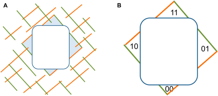
FIGURE 1. Key blocks on boundary of rectangle-shaped tunnel: (A) four key blocks cut by two joint sets and the tunnel boundary; (B) key blocks labeled by their joint pyramid code.
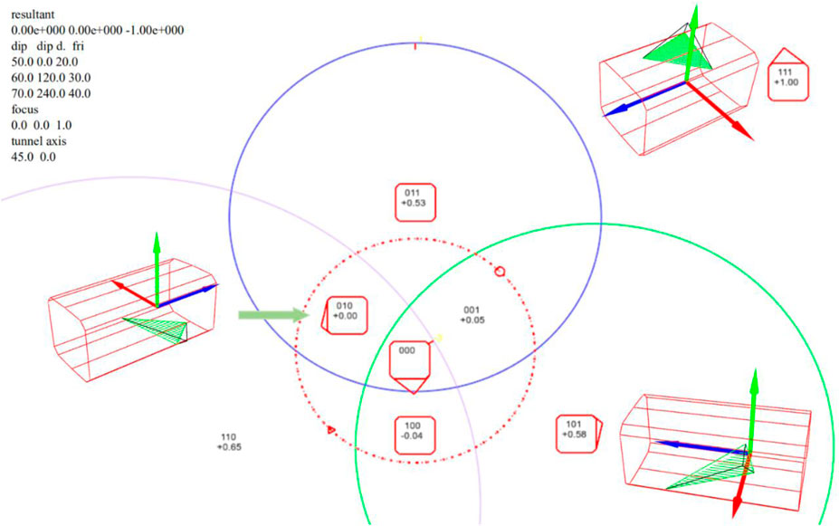
With block theory, key blocks of different joint pyramids can be estimated before excavation, and the shape and volume of the maximum key block can be analyzed. The concept of a maximum block means that the key blocks belonging to the same joint pyramid cannot be removed if they have larger volumes. The maximum key block must correspond to the largest supporting force; thus, block theory provides conservative and safe support suggestions, and it is a useful and efficient tool in engineering. As shown in Figure 2, block theory is used to analyze an underground cavern. There are three main sets of joints in the cavern region whose geometrical parameters (dip direction ∠dip) are 0°∠50°, 120°∠60° and 240°∠70°. And their friction angles are 20°, 30° and 40°, respectively. Different combinations of joint sets form different joint pyramids and key blocks with different excavation surfaces. Block theory requires only a few joint planes; thus, the orientation and location of planes can be directly measured by geological compasses or other equipment on site (Gonzalez-Palacio et al., 2005). Subsequently, the volumes, weight and shapes of the maximum key blocks can be obtained. In Figure 2, the solid circles denote the projections of joints, and the label “101” is the joint pyramid code, which means below joint sets 1 and 3 and above joint set 2. The label “+0.58” (below the joint pyramid code) corresponds to the residual sliding force on a unit volume of the corresponding joint pyramid “101”. The corresponding maximum key blocks for joint pyramids “010”, “111”, and “101” are shown in Figure 2.
In practice, the orientations and locations of fractures and joint sets can be obtained by field survey, and blocks can be generated in two ways: 1) Obtain intersection lines by intersecting the fractures and joint disks. Then, intersection lines are intersected to obtain all the intersection points and final intersection lines. Then, search all the closed loops and save them as polygons. Finally, search the polyhedrons by determining the correlation between the intersection lines and searched polygons (Zhang and Wu, 2005; Zhang and Wu, 2007). 2) Extend all fractures and joint sets into infinite planes. Then, perform the same procedure as in the first approach to find all the polyhedrons. Then, return the infinite planes back to their original sizes. Finally, polyhedrons that share the same imaginary faces are combined (Yu et al., 2005). These two methods are commonly used to obtain approximate blocks, but the second method requires more computation. They are both based on computational geometry and require a discrete fracture network (DFN) model to be established first. Because the orientations of joints are complex and difficult to obtain, stochastic approaches are usually adopted to generate joints (Mauldon, 1993; Ahn and Lee, 2004; Dowd et al., 2009). After block generation, the convex blocks can be analyzed by classic block theory to obtain more accurate results. To make block theory more applicable, researchers have focused on nonconvex blocks Shi and Goodman (1989), Shi (2006), Menéndez-Díaz et al., (2009), Elmouttie et al. (2010) and more complex application scenarios (Fu et al., 2016; Zheng et al., 2016; Wu et al., 2018). Compared to the much more complex stability analysis He et al. (2018), Zhang and Shi (2021) of discontinuous deformation analysis Shi (1992), block theory is a static method that has three features: 1) the removability of blocks is analyzed by geometrical and topological methods; 2) stability is determined by simple mechanical analysis; and 3) only translation movement at the initial moment is considered. Thus, block theory requires much less computational cost and is suitable to find key blocks and provide supporting advice during the survey and construction period of civil engineering projects. To facilitate the utilization of block theory Cheng et al. (2017), three-dimensional visualization for stereographic projection Li et al. (2010) and equilibrium region graphs Xue and Song (2017) have been implemented. However, a general algorithm with which to compute the stability of blocks of arbitrary shapes is still needed.
We focus on finite blocks in this paper, and a general algorithm to analyze the stability of blocks of arbitrary shapes is proposed, as described in Proposed Algorithm. Joint pyramids for blocks of arbitrary shapes can computed by proposed algorithm that based on classical block theory, by which the stability of blocks can be analyzed. Validations and engineering applications are given in Validations and Engineering Applications. Conclusions are given in Conclusion. By means of the method proposed in this paper, dangerous key blocks of arbitrary shapes, such as those at the edges, corners, and portals of underground chambers, can be identified by engineers immediately.
Proposed Algorithm
All blocks formed by fractures of a finite size in a given rock mass domain can be identified using 3D block-cutting analysis. Among these blocks, there may exist blocks that have parallel faces or concave angles formed by fracture surfaces. However, a general key block judgment algorithm for blocks of arbitrary shapes is seldom studied. To make block theory suitable for blocks of any shape, this paper proposes a general algorithm for analyzing block stability. It simplifies faces of arbitrary shapes into joint planes and computes a joint pyramid for the joint planes, even those with concave angles. The algorithm can utilize block theory to create industrial products that everyone can use.
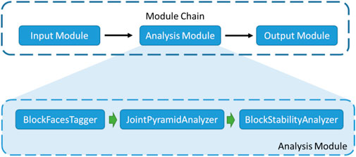
The algorithm has been designed and implemented as a library, whose architecture is shown as Figure 3. The input module reads blocks generated by the 3D cutting process. Then, the analysis module invokes the classes “BlockFacesTagger”, “JointPyramidAnalyzer” and “BlockStabilityAnalyzer” to analyze the stability of each block. Finally, the output module saves and displays the analysis result. The analysis takes the following steps:
1) “BlockFacesTagger” classifies and tag faces of a block and give each face an id according to the face normal vectors (see Grouping and Tagging Block Faces).
2) “JointPyramidAnalyzer” computes the joint pyramid based on the normal vectors from the first step to build the relation between the faces of the block and the joint pyramid (see Computing the Joint Pyramid).
3) “BlockStabilityAnalyzer” computes block stability according to the joint pyramid, e.g., sliding mode (see Analyze Stability of Joint Pyramid).
Grouping and Tagging Block Faces
To analyze the stability of blocks, engineers must simplify the faces of blocks into joint planes first, which is tedious and complex work. To make block theory easier to utilize, the proposed algorithm groups and tags the faces of the block by the face normal vectors and generates joint planes. It has the following steps:
1) Prepare a normal array N and normal id array NI.
2) Iterate through the faces of the block, and check whether each normal already exists in N.
3) If the normal does not exist, identify the current face normal with a size of N and add a new normal into N; otherwise, just use the id of the existing normal.
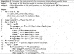
The key steps are described in Algorithm 1.
Algorithm 1 Tagging faces of the block, determined by the face normalsinput: faces of block: F; number of faces: Moutput: Normal array N; normal id array NIBegin:
1 N←
2 fori←0 to M
3 S←size of normal array N
4 forj←0 toS
5 if parallel (Nj, Fi.normal)
6 thenNI←NI∪j;break
7 if j = = S
8 thenNI←NI∪S; N←N∪Fi.normal
Computing the Joint Pyramid
According to block theory, “a convex block is removable if and only if its block pyramid is empty and joint pyramid is not empty” (Goodman and Shi, 1985). Because blocks in the real world are all finite, the block pyramid is always empty; see Eq. 1. Therefore, we only need to consider the joint pyramid, and then the theorem can be simplified as “finite convex blocks are removable if and only if its joint pyramid is not empty”.
In classic block theory, joint pyramids are only used to analyze convex blocks. However, blocks have various shapes in practice, and we must find a general way to compute the joint pyramid. “A finite nonconvex block is a composite block that consists of some finite convex blocks. If all its convex subblocks are removable, the nonconvex block is removable” (Li et al., 2012). If a block is removable, the movement direction must be in the joint pyramid of this block, and the joint pyramid is not empty. Thus, we need to compute the intersection of joint pyramids of all the convex subblocks only. Because the number of joint planes of these joint pyramids is finite, we compute the intersection of all half spaces of the joint planes of this block.
Therefore, a nonconvex block is removable if and only if its joint pyramid is not empty. The joint pyramid of a nonconvex block is the minimum pyramid that belongs to any other combination of half spaces of joint planes of the block. Thus, we need to obtain the orientations of the joint planes first, i.e., dip angles and dip direction angles.
There are four steps to compute the joint pyramid for any number of joint planes, even those with concave edges:
1) Determine all the inward normal vectors of the joint planes.
2) Compute the cross-product for every two normal vectors and save the cross-product vectors if the dot-product between itself and any other normal is positive, then do the same procedure for the reverse vector of the cross-product vector.
3) Simultaneously reserve the face pairs of all the cross-product vectors saved in step 2.
4) Iterate all face pairs, sort them into end-to-end order, and reverse any face pairs if needed.
Algorithm 2 provides a detailed explanation of this computation.
Algorithm 2 Compute the joint pyramid of a nonconvex block without parallel facesinput: Dip angle ai, dip direction angle bi; number of joint planes Moutput: Edge information of the joint pyramid, i.e., the edge vector EV; face pairs of edges FPbegin:
1 fori←0 to M, do
ni←(sinai·sinbi, sinai·cosbi, cosai);
if ith joint plane use below half space then
ni← - ni
2 Edge vector EV←
3 fori←0 to M-1
4 forj←1 to M
5 T1←cross (ni, nj); T2 ←-T1; Flag1←true; Flag2←true
6 fork←0 to M
7 if k = = i OR k = = j then continue
If dot(T1, nk) < 0 then Flag1←false
If dot(T2, nk) < 0 then Flag2←false
8 If Flag1 then EV←EV∪T1, FP←FP∪ (i,j)
if Flag2 then EV←EV∪T2, FP←FP∪ (i,j)
11 N←number of EV
12 fori←0 to M-1//connect edge in end-to-end order
13 forj←1 to M
14 if FPi.seconfFace == FPj.secondFace
15 then swap(FPj.firstFace, FPj.secondFace)
if FPi.secondFace == FPj.firstFace
then swap (Ti+1,Tj) and swap (FPi+1,FPj)
Analyze Stability of Joint Pyramid
According to block theory, a block is in a stable mode if its joint pyramid is empty, which means that there is no space available to move into. Otherwise, there are three types of translational failure modes: lifting, single-face sliding and double-face sliding.
If a block is in lifting mode, the motion direction
where
If a block slides along one face of its joint pyramid, i.e., sliding along one face or parallel faces of the block. If the index of the sliding face is
where
If a block slides along two nonparallel faces
where
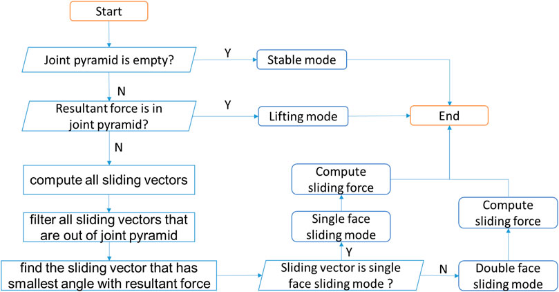
To compute the stability of the joint pyramid, all the sliding vectors need to be computed to find the final sliding mode. This requires the following steps, as shown in Figure 4:
1) If the joint pyramid is empty, the block is in a stable mode; go to step 7; otherwise, go to the next step.
2) Check if the resultant force is in the joint pyramid. If it is in, the block is in lifting mode, and go to step 7; otherwise, go to the next step.
3) Compute all the single-face sliding vectors and double-face sliding vectors.
4) Filter all the sliding vectors that are out of the joint pyramid.
5) Find the sliding vector that has the smallest angle with the resultant force, which corresponds to the final sliding direction, from the filtered vectors.
6) Judge the sliding mode and compute the sliding force for the final sliding direction.
7) Process ends.
Validations
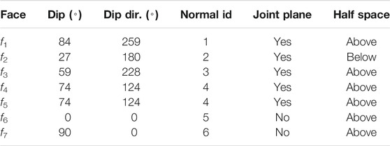
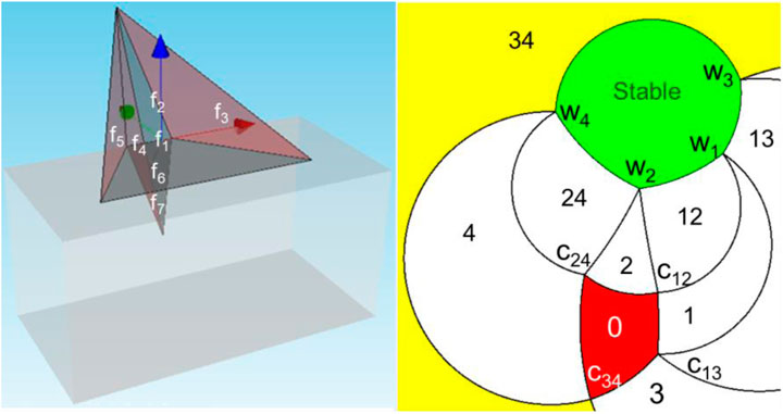
In this section, the correctness and feasibility of the proposed algorithm are verified by block with parallel faces and concave angles. This block is on the edge of a tunnel, and its faces are tagged with f1, f2, f3, f4, f5, f6, and f7, and the normal ids of the faces are tagged with 1, 2, 3, 4, 4, 5, and 6. Among these faces, f4 and f5 are parallel, while f1 and f3 form a concave edge. Faces f6 and f7 of the block are located on the boundary of tunnel, so they act as space planes, and all the other faces are used as joint planes, as shown in Table 1. Under gravity force, i.e. (0, 0, −1), the concave block is in the double-face sliding mode along faces f3, f4 and f5, and the sliding force of unit weight is 0.806, as shown in Figure 5.
Engineering Applications
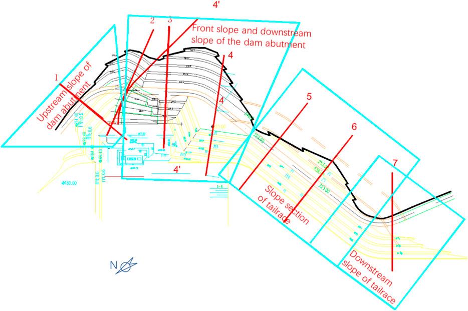
The proposed algorithm is used to study the stability of the left bank of a dam in China. The left bank slope is excavated on a large scale, and the strike of the excavated slope changes significantly, showing a different angle with the strike of the rock stratum, as shown in Figure 6. According to the direction of the excavation slope and the different engineering positions, the left bank slope is divided into four slope sections: 1) the upstream slope of the dam abutment, 2) the front and the downstream slope of the dam abutment, 3) the tailrace slope, and 4) the downstream slope of the tailrace canal.
The average occurrence of the strata is 268∠39° (dip direction ∠dip), with some interlayer shear zones developed. There are three main sets of joints developed in the rock mass. The joints are straight and closed, with a calcite film attached. The geometric and mechanical features of the discontinuities considered in the analysis are shown in Table 2.
When adopting block theory, it is necessary to analyze only the blocks formed by the combination of the strata and the joints. The blocks formed by a combination of joints are omitted due to their small volume, and the stability of this kind of block can be ensured by a general slope hanging net and anchor rod support system. Generally, gravity is considered the only force applied to the blocks.
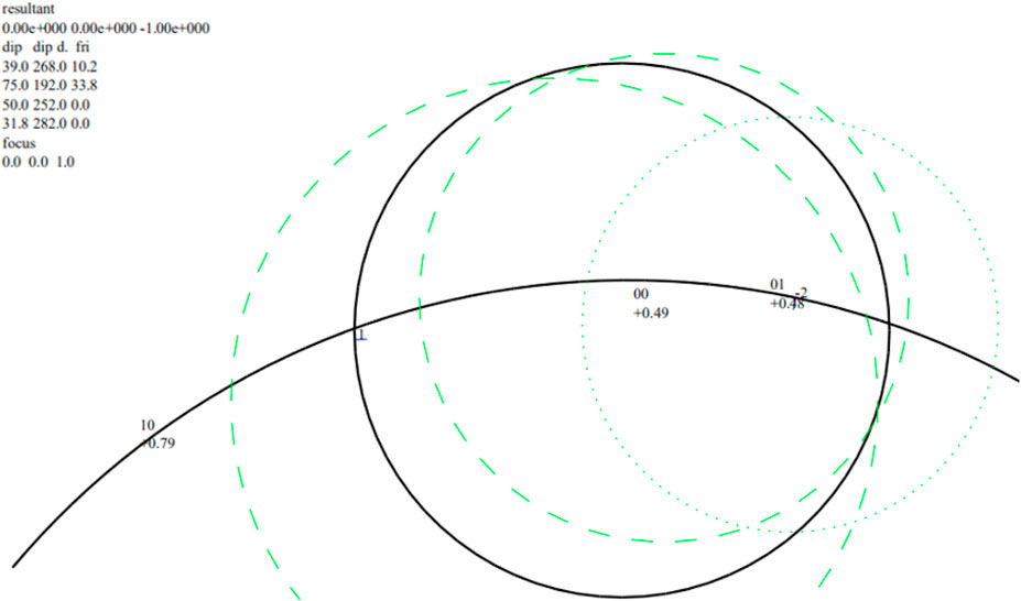
Using full-space stereographic projection analysis, the removable joint pyramids and their sliding modes of different slope sections are obtained. See Table 3. Among them, the stereographic projection of the slope near section 1 is shown in Figure 7.
1) For the same slope section, if the result of the stereographic projection analysis shows that there are two or more types of removable blocks, then only blocks with a poor stability, large scale, or high support requirement need to be analyzed in the block stability and engineering support analysis. When the stability of this type of block is ensured, other types of removable blocks are stabilized.
2) When only the effect of gravity is considered, the double-face sliding mode has a smaller safety factor if both faces are upward. Therefore, if there are joint pyramids “00” and “01” at the same slope section, only the blocks formed by joint pyramid “00” need to be analyzed.
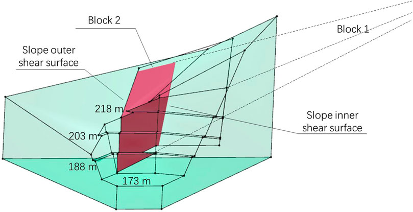
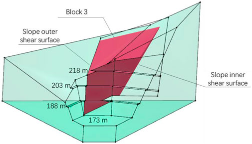
The strata on the upstream slope of the dam abutment incline outward, and the strata direction (strike 178°, dip direction 268°) is close to the slope direction (strike 162°, dip direction 252°). According to the qualitative analysis of engineering geology, the slope is a near-forward slope, and the blocks exhibit a single-face sliding mode along the strata. According to the analysis of the full-space stereographic projection, when combining interlayer shear zone II1-7005 with the fractures of the NWW group, block 1 in Figure 8 can be formed, and the block is in a single-face sliding mode along the interlayer shear zone. The block traces the NWW group and forms a shear zone. Since zone II1-7005 is exposed at the ∇173 m platform, the block with the largest body is formed when the shear surface passes through the intersection of zone II1-7005 and ∇173 m. However, the block may be unremovable due to the shape restriction. In fact, it is more reasonable to cut the rock at a certain position on the inner side of the slope to form a shear surface, i.e., Block 2 in Figure 8 and Block 3 in Figure 9.
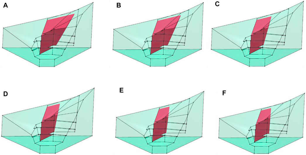
The shear surface on the inner side of the slope follows other cracks or shear surfaces that cut through the rock mass. With the different orientations of the inner shear surfaces of the slope, the shape and stability of the blocks are different. Thus, to determine the final support design, the orientation of the inner shear surface of the slope with the smallest safety factor must be identified. Within the possible variation range of the dip direction, the shape characteristics of blocks are shown in Figure 10, and the stability is shown in Table 4. The analysis results show that when the shear surface orientation is 350°∠85°, the safety factors of the blocks in Figure 10E, F and have the same value of 0.222, which is the smallest value calculated in this case, and the sliding mode of the blocks is single-face sliding. However, the block in Figure 10F is more dangerous because of its larger volume.
The conclusion obtained by the analysis of block theory is similar to the qualitative analysis of engineering geology. The block undergoes single-face sliding with the interlayer shear zone as the sliding face, but the block theory clearly identifies the shear surface through the analysis of block morphology. When the orientation of the shear surface is different, the sliding mode of the block can transition from double-face sliding to single-face sliding. Accordingly, the safety factor of the block changes.
The spatial position of the block can be analyzed after determining the orientation of the shear surface. In different positions, the size and shape of the blocks are different, and the stability is different as well. Therefore, it is necessary to compute the safety factors of blocks of different sizes and shapes within the possible range of block sizes to fully describe the stability characteristics of this type of block. The analysis results show that when a block is as large as possible, its safety factor is smaller; the largest possible block is shown in Figure 11. The volume of this block is 45,808 m3.
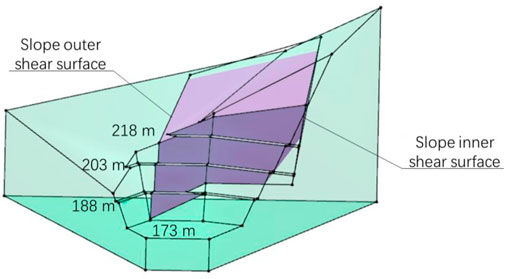
FIGURE 11. The shape of this block suggests that support is needed on the upstream slope of the dam.
Conclusion
In this paper, we propose a general block stability analysis algorithm based on the traditional block theory analysis framework. It has 2 advantages: first, parallel or nonadjacent sliding faces with the same normal vector can be identified immediately, which may provide more detailed support advice for engineers; second, the joint pyramids and removability of blocks of arbitrary shapes can be computed, which greatly enhances the applicability of block theory. The feasibility of the proposed algorithm in treating blocks with parallel faces and concave angles is verified first. Then, the proposed algorithm is used to locate the key block on the left bank slope of a dam in China, and the final key block identified using the proposed algorithm is similar to that identified via a qualitative engineering geology analysis. Using this proposed algorithm, engineers can analyze block stability and find key blocks of arbitrary shapes at any position without the additional cost of interpreting graphs of block theory, which could greatly promote the development and application of block theory.
Data Availability Statement
The original contributions presented in the study are included in the article/supplementary material, further inquiries can be directed to the corresponding author.
Author Contributions
XC developed the algorithm and wrote the manuscript; LL performed the experiments and participated in writing the manuscript; JX contributed significantly to analysis and manuscript preparation; QZ performed the engineering application; JX helped perform the analysis with constructive discussions. YW contributed to the conception of the study.
Funding
This work was supported by the Strategic Priority Research Program of the Chinese Academy of Sciences (No. XDA23090304), the China Postdoctoral Science Foundation (2019M650816), the Fundamental Research Funds for the Central Universities, the National Natural Science Foundation of China (U2003109), and the Youth Innovation Promotion Association of the Chinese Academy of Sciences (Y201935). Thanks to Northwest Engineering Corporation Limited for their support.
Conflict of Interest
The authors declare that the research was conducted in the absence of any commercial or financial relationships that could be construed as a potential conflict of interest.
Publisher’s Note
All claims expressed in this article are solely those of the authors and do not necessarily represent those of their affiliated organizations, or those of the publisher, the editors and the reviewers. Any product that may be evaluated in this article, or claim that may be made by its manufacturer, is not guaranteed or endorsed by the publisher.
Acknowledgments
Thanks to Gen-hua Shi for his careful guidance and help. Thanks to JX for his careful guidance and help.
References
Ahn, S. H., and Lee, C. I. (2004). Removability Analysis of Rock Blocks by Block Theory and a Probabilistic Approach. Int. J. Rock Mech. Mining Sci. 41 (Suppl. 1), 429. doi:10.1016/j.ijrmms.2003.12.069
Cheng, X. L., Wang, Y., Xue, J., Miao, Q. H., and Xiao, J. (2017). A New Software for Block Theory and its Applications in Rock Engineering. 51st US Rock Mechanics/Geomechanics Symposium. American Rock Mechanics Association.
Dowd, P. A., Martin, J. A., Xu, C., Fowell, R. J., and Mardia, K. V. (2009). A Three-Dimensional Fracture Network Data Set for a Block of Granite. Int. J. Rock Mech. Mining Sci. 46 (5), 811–818. doi:10.1016/j.ijrmms.2009.02.001
Elmouttie, M., Poropat, G., and Krähenbühl, G. (2010). Polyhedral Modelling of Underground Excavations. Comput. Geotechnics. 37 (4), 529–535. doi:10.1016/j.compgeo.2010.02.009
Fu, G. Y., Ma, G. W., Qu, X. L., and Huang, D. (2016). Stochastic Analysis of Progressive Failure of Fractured Rock Masses Containing Non-Persistent Joint Sets Using Key Block Analysis. Tunnelling Underground Space Technol. 51, 258–269. doi:10.1016/j.tust.2015.10.013
González-Palacio, C., Menéndez-Díaz, A., Álvarez-Vigil, A. E., and González-Nicieza, C. (2005). Identification of Non-Pyramidal Key Blocks in Jointed Rock Masses for Tunnel Excavation. Comput. Geotechnics. 32 (3), 179–200. doi:10.1016/j.compgeo.2005.01.004
Goodman, R. E., and Shi, G. H. (1985). Block Theory and its Application to Rock Engineering. Englewood Cliffs, New York: Prentice Hall.
He, L., Tian, Q., Zhao, Z., Zhao, X., Zhang, Q., and Zhao, J. (2018). Rock Slope Stability and Stabilization Analysis Using the Coupled DDA and FEM Method: NDDA Approach. Int. J. Geomech. 18 (6), 04018044. doi:10.1061/(asce)gm.1943-5622.0001098
Li, J. Y., and Xiao, J. (2010). Simulation Method of Rock Stability Analysis Based on Block Theory. Comput. Eng. Appl. 46 (21), 4–8. doi:10.1007/s12209-016-2596-z
Li, J. Y., Xue, J., Xiao, J., and Wang, Y. (2010). Three Dimensional Sphere Analysis Method of Block TheoryInternational Conference on Computer Application and System Modeling. (ICCASM 2010). 1, V1–V578. doi:10.1109/iccasm.2010.5620625
Li, J., Xue, J., Xiao, J., and Wang, Y. (2012). Block Theory on the Complex Combinations of Free Planes. Comput. Geotechnics. 40, 127–134. doi:10.1016/j.compgeo.2011.10.006
Mauldon, M. (1993). Variation of Joint Orientation in Block Theory Analysis. Int. J. Rock Mech. Mining Sci. Geomechanics Abstr. 30 (7), 1585–1590. doi:10.1016/0148-9062(93)90161-6
Menéndez-Díaz, A., González-Palacio, C., Álvarez-Vigil, A. E., González-Nicieza, C., and Ramírez-Oyanguren, P. (2009). Analysis of Tetrahedral and Pentahedral Key Blocks in Underground Excavations. Comput. Geotechnics. 36 (6), 1009–1023. doi:10.1016/j.compgeo.2009.03.013
Shi, G. H. (1977). Stereographic Method for the Stability Analysis of the Discontinuous Rocks. Scintia Sin. 3.
Shi, G. H. (1982). A Geometric Method for Stability Analysis of Discontinuous Rocks. Entia Sinica. 3, 125–143.
Shi, G. H. (1992). Discontinuous Deformation Analysis: A New Numerical Model for the Statics and Dynamics of Deformable Block Structures. Eng. Computations. 9 (2), 157–168. doi:10.1108/eb023855
Shi, G. H. (2006). Producing Joint Polygons, Cutting Joint Blocks and Finding Key Blocks for General Free Surfaces. Chin. J. Rock Mech. Eng. 25 (11), 2161–2170.
Shi, G.-h., and Goodman, R. E. (1989). The Key Blocks of Unrolled Joint Traces in Developed Maps of Tunnel walls. Int. J. Numer. Anal. Methods Geomech. 13 (2), 131–158. doi:10.1002/nag.1610130203
Sun, G., Zheng, H., and Huang, Y. (2015). Stability Analysis of Statically Indeterminate Blocks in Key Block Theory and Application to Rock Slope in Jinping-I Hydropower Station. Eng. Geology. 186 (Suppl. 1), 57–67. doi:10.1016/j.enggeo.2014.09.012
Wu, W., Zhu, H. H., Lin, H. S., Zhuang, X. Y., and Ma, G. W. (2018). Tunnel Stability Assessment by 3d Dda-Key Block analysis. Tunneling and Underground Space Technology. 71, 210–214. doi:10.1016/j.tust.2017.07.015
Xue, J., and Song, X. X. (2017). 3d Graphical Visualization for Block Theory. 51st US Rock Mechanics/Geomechanics Symposium. California, USA: American Rock Mechanics Association.
Yu, Q. C., Chen, D. J., Xue, G. F., and Ohnishi, Y. (2005). Preliminary Study on General Block Method of Fractured Rock Mass. Hydrogeology & Engineering Geology. 2005(11), 42–48.
Zhang, Q. H., and Wu, A. Q. (2005). Morphological Analysis Method of Block Based on Classification of Concave Zone. Chin. Jorunal Geotechnical Eng. 27 (3), 299–303.
Zhang, Q. H., and Wu, A. Q. (2007). General Methodology of Spatial Block Topological Identification with Stochastic Discontinuities Cutting. Yanshilixue Yu Gongcheng Xuebao/chinese J. Rock Mech. Eng. 26 (10), 2043–2048.
Zhang, Q.-H., and Shi, G.-H. (2021). Verification of a DDA-Based Hydro-Mechanical Model and its Application to Dam Foundation Stability Analysis. Int. J. Rock Mech. Mining Sci. 138, 104627. doi:10.1016/j.ijrmms.2021.104627
Zhang, Q.-h., Wu, A.-q., and Zhang, L.-j. (2014). Statistical Analysis of Stochastic Blocks and its Application to Rock Support. Tunnelling Underground Space Technol. 43 (jul), 426–439. doi:10.1016/j.tust.2014.06.005
Zheng, J., Kulatilake, P. H. S. W., Shu, B., Sherizadeh, T., and Deng, J. (2014). Probabilistic Block Theory Analysis for a Rock Slope at an Open Pit Mine in usa. Comput. Geotechnics. 61 (3), 254–265. doi:10.1016/j.compgeo.2014.06.002
Keywords: block theory, sliding mode, arbitrary shape block, key block, engineering application
Citation: Cheng XL, Liu LP, Xiao J, Zhang QH, Xue J and Wang Y (2021) A General Block Stability Analysis Algorithm for Arbitrary Block Shapes. Front. Earth Sci. 9:723320. doi: 10.3389/feart.2021.723320
Received: 29 June 2021; Accepted: 13 July 2021;
Published: 23 July 2021.
Edited by:
Xiaodong Fu, Institute of Rock and Soil Mechanics (CAS), ChinaReviewed by:
Wei Wu, Tongji University, ChinaJianyong Li, North China University of Water Conservancy and Electric Power, China
Copyright © 2021 Cheng, Liu, Xiao, Zhang, Xue and Wang. This is an open-access article distributed under the terms of the Creative Commons Attribution License (CC BY). The use, distribution or reproduction in other forums is permitted, provided the original author(s) and the copyright owner(s) are credited and that the original publication in this journal is cited, in accordance with accepted academic practice. No use, distribution or reproduction is permitted which does not comply with these terms.
*Correspondence: Jun Xiao, eGlhb2p1bkB1Y2FzLmFjLmNu
 Xiao Long Cheng
 Lu Peng Liu
 Jun Xiao1*