- 1School of Petrochemical Engineering and Environment, Zhejiang Ocean University, Zhoushan, China
- 2School of Petroleum Engineering, China University of Petroleum (East China), Qingdao, China
Ferrofluid is a kind of magnetic fluid, the flow of which is controlled by an external magnetic field. Owing to this property, ferrofluid, as a new function material, has raised extensive concern in the oil industry. In this paper, the issue of ferrofluid flow in complex porous media has been studied by numerical simulation, and the validity and accuracy of the numerical algorithm are demonstrated through a 1-D horizontal tube example. Later, the effects of the magnetic force on ferrofluid flow in complex porous media, such as heterogeneous and fractured porous media, are investigated. The results show that there is basically no flow in low permeability or secondary fracture without a magnetic field, due to the characteristics of porous media and displacement pressure distribution. However, the ferrofluid flow velocity and domain can be changed by applying an external magnetic field. This novel phenomenon may provide a new idea to enhance oil recovery based on controllable flooding technology or meet other industrial needs by using ferrofluid.
Introduction
Water flooding, as is well recognized, is an effective approach to maintain reservoir pressure and improve oil recovery. However, heterogeneities or fractures present in reservoirs can significantly decrease the sweep efficiency, leading to poor utilization ratios, and low oil recovery (Qitai, 2000; Han, 2007; Li, 2009). Therefore, how to change the direction of the displacement fluid to increase the flooding area plays a vital role in enhancing oil recovery. At present, there are many methods to achieve that. First, the subsurface fluid flow can be regulated by optimizing the well production and injection. Second, increasing rock permeability in low-sweep zones, such as by fracturing and acidizing methods (Zeng et al., 2018; Lei et al., 2019; Lu et al., 2020; Zeng et al., 2020; Jia et al., 2021), can significantly improve the flow capacity of the zones. In addition, it is also an alternative to apply polymer flooding or surfactant flooding to change the properties of the displacement fluid and reduce its flow ability in high-sweep zones or increase its flow ability in low-sweep zones (Zhu et al., 2019a; Zhu et al., 2019b; Sidiq et al., 2019). However, all of the above methods are time-consuming and labor-intensive work.
Ferrofluid is a stable colloid composed of nanoscale magnetic particles (usually magnetite, Fe3O4) which are coated with a molecular layer of a dispersant (amphiphilic molecules, like oleic acid) and suspended in a liquid carrier (Popplewell and Charles, 1981), as is shown in Figure 1. Ferrofluid exhibits the characteristics of a general fluid in that its motion follows the hydrodynamic law. However, it is a magnetic substance that receives the magnetic body force in the presence of an external magnetic field, so that its behavior and property can be controlled by the magnetic field (Odenbach, 2008). The idea of creating a colloidal fluid with ferromagnetic properties was put forward independently and almost simultaneously by several investigators. One of the first and most easily prepared colloidal systems was developed by NASA in the early 1960’s (Rosensweig, 1982). At present, ferrofluid has many industrial applications, such as dynamic sealing, inertial and viscous damper, magnetic drug targeting, liquid microrobots, and so on (Raj and Moskowitz, 1990; Hou et al., 1999; Scherer and FigueiredoNeto, 2005; Fan et al., 2020). Recently, researchers have been studying the potential of using ferrofluid to detect fractures and heterogeneity in reservoirs (Sengupta, 2012; Rahmani et al., 2015).
In this paper, we focus on the ferrofluid flow in porous media using the numerical simulation method based on the finite element method. First, the validity and accuracy of the model and the numerical algorithm are demonstrated. Then, several problems of the heterogeneous and fractured porous media flow are studied. The results show that the ferrofluid flow in complex porous media can be manipulated by applying an external magnetic field. For example, the flow velocity and the flow region can be changed under the action of magnetic force. This phenomenon may provide a new idea for enhancing oil recovery, such as using ferrofluid as controllable displacement fluid in complex or unconventional reservoirs.
Computational Methodology
Magnetic Body Force
When applying an external magnetic field, the secondary magnetic field produced by the magnetic particles in the ferrofluid and the interaction between the two magnetic fields produce a magnetic body force on the ferrofluid (Neuringer and Rosensweig, 1964):
where
We considered a water-based ferrofluid whose properties are provided by a nanomaterial company in China. Its viscosity and density respectively equal 5.8 mPa∙s and 1,187 kg/m3. Although the composition of the fluid was not offered, the magnetization curve of the fluid was provided to us as is shown in Figure 2. The ferrofluid magnetization curve can be generally approximated by simple two-parameter arctan functions of the form (Oldenburg et al., 2000):
where
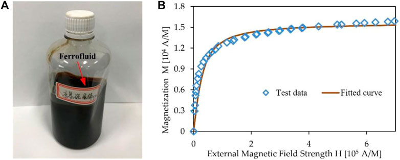
FIGURE 2. Schematic diagram of ferrofluid: (A) A bottle of water-based ferrofluid; (B) Magnetization vs. magnetic field strength curve of the ferrofluid.
Calculation of Magnetic Field
In this paper, the external magnetic field provided by the NdFeB magnets and the three-dimensional magnetic field could be calculated by analytic equations (Maccaig, 1987):
where,
Single-phase Ferrofluid Flow Equations
For a ferrofluid affected by an external magnetic field, a body force Fm is produced, as is shown in Eq. 1. Thus, an additional magnetic force term appears in Darcy’s equation:
where
where
Finite Element Discretization
In this paper, we only take the isothermal flow of impressible single-phase ferrofluid into consideration whereas we neglect the impact of gravity for simplicity, which is similar to the analysis of other flow problems. Eqs.7, 8 can be simplified as:
Define mobility as
The Galerkin weighted residual method is used to derive the formulation of the finite element in the above equation:
where
The finite element approximation of the pressure
where
where
Verification of Algorithm
Morris et al. set up a one-dimensional experimental system to verify the validity of the magnetic force expression by comparing the experimental and theoretical results (Moridis et al., 1998). Here we used this method to verify the correctness of the algorithm.
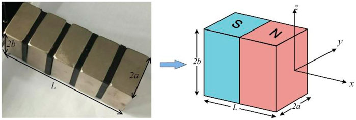
Consider a one-dimensional closed horizontal tube model with a radius that is small enough to approximate the porous media. The tube is filled with ferrofluid and a magnet is placed on the left side, as is shown in Figure 4. The length
For the 1-D model, combined Eqs 3, 4, the calculation of magnetic field strength can be simplified as:
Based on the Eq.15, the magnetic field strength gradient can be obtained:
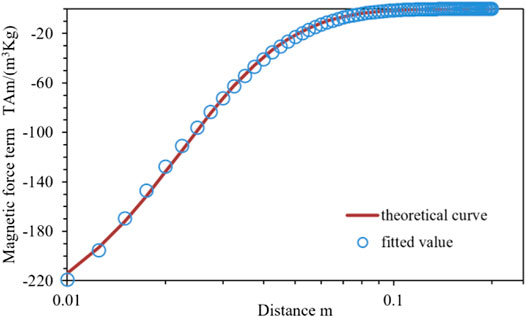
Combining Eqs 1, 2, 16, the magnetic force term
where these coefficients
Because the tube is closed and horizontal,
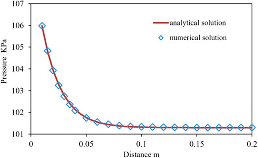
Solving the above equation, the analytic solution of pressure can be obtained:
where
Examples and Discussions
Porous Media With Horizontal Heterogeneities
Consider two 1/4 five-spot horizontal heterogeneous porous media models, as Figure 7 shows, both with a size of 0.2 m × 0.2 m. The first model contains elliptical high-permeability zones while the second model contains elliptical low-permeability zones. The former permeability is 1.0 × 10⁻¹³ m2 and the latter permeability is 1.0 × 10⁻¹⁶ m2. Assuming both models have a porosity of 0.2 it are outside of the elliptical zones, then the permeability will be 1.0 × 10⁻¹⁴ m2. The injection and production rates of both models were set to 1.0 PV/min, where PV is the total pore volume. The initial pressure is 101.3 × 10³ Pa. Two magnets were placed on both porous media models, as is shown in Figure 7, and the magnet properties have been mentioned in Verification of Algorithm.
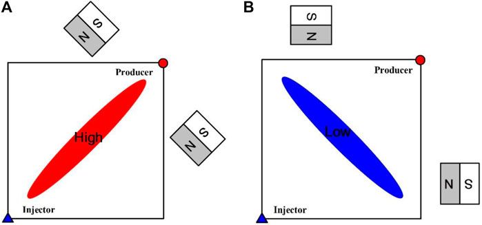
FIGURE 7. Two different kinds of heterogeneous porous media models and the location of permanent magnets: (A) Porous media with a high-permeability zone; (B) Porous media with a low-permeability zone.
For the former heterogeneous model, the injected ferrofluid mainly flows through the high permeability zone when there is no external magnetic field (the size and direction of black arrows represent the flow velocity). While in the lower permeability area, ferrofluid is barely flowing because the pressure gradient is too low, as is shown in Figure 8C
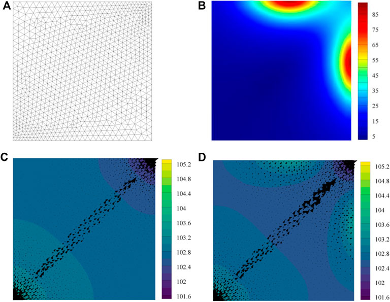
FIGURE 8. Distribution of ferrofluid pressure and external magnetic field strength, the black arrow stands for flow velocity: (A) Mesh grid; (B) External magnetic field strength, 103A/m; (C) Pressure map without external magnetic field influence, KPa; (D) Pressure map with external magnetic field influence, KPa.
However, when applied to an external magnetic field (Figure 8B), ferrofluid begins to flow towards the magnets and the pressure increases under the effect of the magnetic force. The magnetic force acts as a “shunt effect,” as is shown in Figure 8D.
For the latter heterogeneous porous media, the flow velocity in the low permeability zone is nearly zero. Ferrofluid flows bypassing the low permeability zone and the velocity is low when there is no external magnetic field, as is shown in Figure 9C.
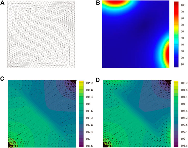
FIGURE 9. Distribution of ferrofluid pressure and external magnetic field strength, the black arrow stands for flow velocity: (A) Mesh grid; (B) External magnetic field strength, 103A/m; (C) Pressure map without external magnetic field influence, KPa; (D) Pressure map with external magnetic field influence, KPa.
When an external magnetic field is applied (Figure 9B), the magnetic force speeds up the flow of ferrofluid around the low permeability zone which leads to a “drainage effect.” The magnetic force leads to the flow velocity and the fluid pressure increases, as is shown in Figure 9D.
Porous Media With Fractures
The fractures’ geometric configuration was simplified by using the discrete-fracture method (Huang et al., 2011). Assuming the representative element volumes of both matrix and fracture system exist, and the flow equations (FEQ) are applied to the entire research area, then for the discrete-fracture model, the integral form of the flow equation can be expressed as:
where
Consider two horizontal fractured porous media models as are shown in Figure 10, and the model size is 0.2 m× 0.2 m. The aperture of fracture equals 1 mm, and the permeability of fracture is 8.33 × 10⁻¹⁰ m2. The other parameters are the same as mentioned above. Both two models have the same magnetic field as is shown in Figure 8B.
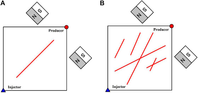
FIGURE 10. Two different kinds of fractured porous media models and the location of permanent magnets: (A) Porous media with a single-fracture; (B) Porous media with multiple-fracture.
Because fracture is regarded as a kind of preferential pathway, the injected ferrofluid mainly flows along with the primary fractures (between the injector and producer), but the ferrofluid in the matrix or secondary fractures hardly flow, as is shown in Figure 11C,E (the red and black arrows stand for flow velocity in fractures and matrix respectively). When an external magnetic field is applied, the ferrofluid is forced to flow towards the magnet. As a result, the flow velocity in the primary fracture decreases and the ferrofluid in the matrix and secondary fractures begins to flow, as is shown in Figure 11D,F.
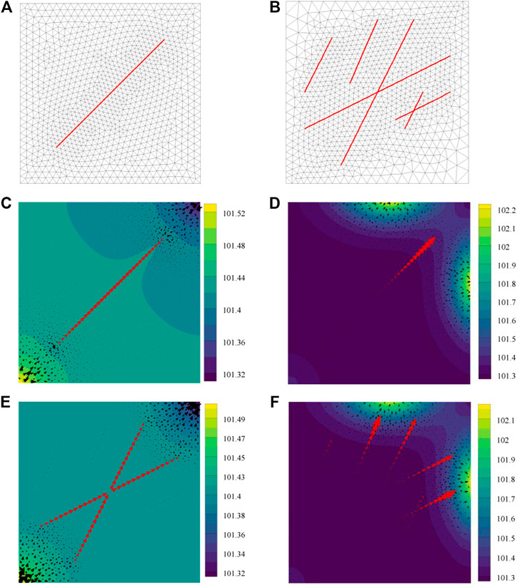
FIGURE 11. Distribution of ferrofluid pressure, the red and black arrows stand for flow velocity in fractures and matrix respectively: (A) Mesh grid of single-fracture model; (B) Mesh grid of multiple-fracture model; (C) Pressure map of single-fracture model without external magnetic field influence, KPa; (D) Pressure map of single-fracture model with external magnetic field influence, KPa; (E) Pressure map of multiple-fracture model without external magnetic field influence, KPa; (F) Pressure map of multiple-fracture model with external magnetic field influence, KPa.
Heterogeneous and Fractured Porous Media
Consider a heterogeneous and fractured porous media model as is shown in Figure 12A, and the model size is 0.6 m × 0.2 m. The magnetic field and heterogeneous permeability map are shown in Figure 12B,C.
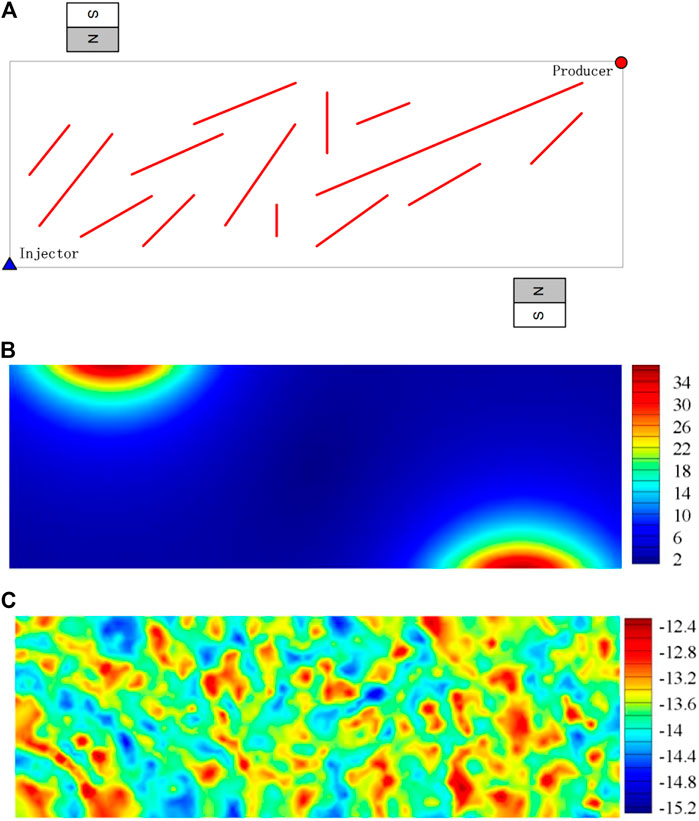
FIGURE 12. A heterogeneous and fractured porous media model and the location of permanent magnets: (A) Model diagram; (B) External magnetic field strength, 103A/m; (C) Permeability map, log10(K).
When there is no external magnetic field, the ferrofluid mainly flows in the fractures and the matrix with high permeability between injector and producer, as is shown in Figure 13B. However, the fluid flows slowly in the upper left and lower right corners of the reservoir due to the small pressure gradient.
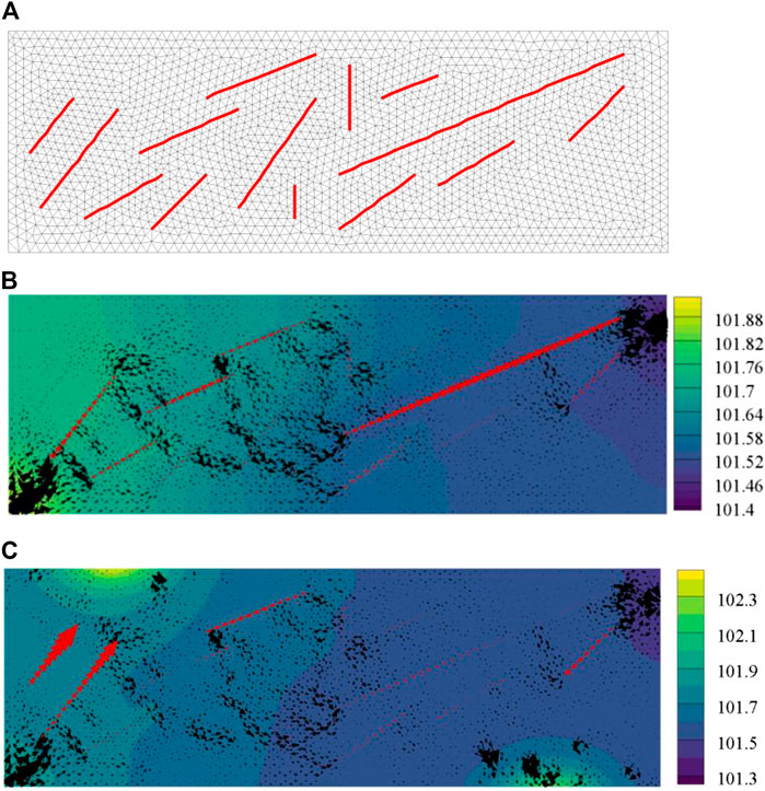
FIGURE 13. Distribution of ferrofluid pressure, the red and black arrows stand for flow velocity in fractures and matrix respectively: (A) Mesh grid; (B) Pressure map without external magnetic field influence, KPa; (C) Pressure map with external magnetic field influence, KPa.
Instead, if an external magnetic field (shown in Figure 12B) was applied, the flow state of the ferrofluid was changed, as is shown in Figure 13C. First, the flow velocity of the fluid in the matrix and fractures near the magnet increased due to magnetic force. Second, the flow velocity in the area far away from the magnetic source became relatively small. Third, the direction of fluid flow in some fractures is even reversed because the magnetic field force overcomes the displacement pressure gradient. The above results show that the flow of ferrofluid can be significantly affected by the external magnetic field, and therefore, its flow can be changed and the flow region can be expanded.
Conclusion
In this paper, the ferrofluid flow in complex porous media is investigated. The magnetic force is introduced into the Darcy equation and the Galerkin finite element method is used for discrete equations. From the simulation results, it is found that the ferrofluid flow in complex porous media can be manipulated by applying an external magnetic field. Moreover, some interesting phenomenon during ferrofluid flow in heterogeneous and fractured porous media have been found: 1) there is basically no flow in low permeability areas or secondary fractures without a magnetic field due to small displacement pressure; and 2) the ferrofluid flow direction and velocity can be changed, so that the magnetic force allows this magnetic fluid to be manipulated to flow in the desired direction through control of the external magnetic field, and makes the flow area larger.
Data Availability Statement
The original contributions presented in the study are included in the article/Supplementary Material, further inquiries can be directed to the corresponding author.
Author Contributions
TH conceived the idea and wrote the manuscript. XL, ZH, and RW contributed to the study and gave final approval for the manuscript.
Funding
This work was supported by the Fundamental Research Funds for Zhejiang Provincial Universities and Research Institutes (Grant No. 2020J00009), the National Natural Science Foundation of China (Grant No. 52004246); the Natural Science Foundation of Zhejiang Province (Grant No. LQ20E040003, Grant No. LY20D020002); the Science and Technology Project of Zhoushan Bureau (Grant No. 2021C21016).
Conflict of Interest
The authors declare that the research was conducted in the absence of any commercial or financial relationships that could be construed as a potential conflict of interest.
References
Fan, X., Sun, M., Sun, L., and Xie, H. (2020). Ferrofluid Droplets as Liquid Microrobots with Multiple Deformabilities. Adv. Funct. Mater. 30, 2000138. doi:10.1002/adfm.202000138
Han, D. (2007). Precisely Predicting Abundant Remaining Oil and Improving the Secondary Recovery of Mature Oilfields. Acta Petrolei Sinica 28, 73–38. doi:10.3321/j.issn:0253-2697.2007.02.013
Hou, H., Zhang, S., and Yang, N. (1999). Development on the Hydro-Magnetic Technology and its Application. Vacuum Technology Mater. 5, 8–12. doi:10.13385/j.cnki.vacuum.1999.05.003
Huang, Z., Yao, J., and Wang, Y. (2011). Numerical Simulation on Water Flooding Development of Fractured Reservoirs in a Discrete-Fracture Model. Chin. J. Comput. Phys. 1, 41–49. doi:10.19596/j.cnki.1001-246x.2011.01.006
Jia, C., Sepehrnoori, K., Huang, Z., and Jun, Y. (2021). Modeling and Analysis of Carbonate Matrix Acidizing Using a New Two-Scale Continuum Model. SPE J., 1–30. doi:10.2118/205012-PA
Lei, Q., Guan, B., Cai, B., Wang, X., Xu, Y., Tong, Z., et al. (2019). Technological Progress and Prospects of Reservoir Stimulation. Pet. Exploration Development 46, 605–613. doi:10.1016/s1876-3804(19)60040-6
Li, Y. (2009). Study on Enhancing Oil Recovery of continental Reservoir by Water Drive Technology. Acta Petrolei Sinica 30, 396–399. doi:10.3321/j.issn:0253-2697.2009.03.013
Lu, M., Su, Y., Zhan, S., and Almrabat, A. (2020). Modeling for Reorientation and Potential of Enhanced Oil Recovery in Refracturing. Adv. Geo-energ. Res. 4, 20–28. doi:10.26804/ager.2020.01.03
Moridis, G. J., Borglin, S. E., and Oldenburg, C. M. (1998). Theoretical and Experimental Investigations of Ferrofluids for Guiding and Detecting Liquids in the Subsurface. Office of Scientific & Technical Information Technical Reports. Berkeley. doi:10.2172/296663
Neuringer, J. L., and Rosensweig, R. E. (1964). Ferrohydrodynamics. Phys. Fluids 7, 1927. doi:10.1063/1.1711103
Oldenburg, C. M., Borglin, S. E., and Moridis, G. J. (2000). Numerical Simulation of Ferrofluid Flow for Subsurface Environmental Engineering Applications. Transport in Porous Media 38, 319–344. doi:10.1023/a:1006611702281
Popplewell, J., and Charles, S. (1981). Ferromagnetic Liquids - Their Magnetic Properties and Applications. IEEE Trans. Magn. 17 (6), 2923–2928. doi:10.1109/tmag.1981.1061670
Qitai, Y. (2000). Three Major Rich Areas of “Large Scale” Unswept Remaining Oil in Water Flooded Bedded Sandstone Reservoirs. Acta Petrolei Sinica 21, 45–50. doi:10.7623/syxb200002009
Rahmani, A. R., Bryant, S. L., and Huh, C. (2015). “Characterizing Reservoir Heterogeneities Using Magnetic Nanoparticles,” in Proceedings of the SPE Reservoir Simulation Symposium, Houston, USA, February 23–25, 2015 (Houston: SPE).
Raj, K., and Moskowitz, R. (1990). Commercial Applications of Ferrofluids. J. Magnetism Magn. Mater. 85, 233–245. doi:10.1016/0304-8853(90)90058-x
Rosensweig, R. E. (1982). Magnetic Fluids. Sci. Am. 247, 136–145. doi:10.1038/scientificamerican1082-136
Scherer, C., and Figueiredo Neto, A. M. (2005). Ferrofluids: Properties and Applications. Braz. J. Phys. 35, 718–727. doi:10.1590/s0103-97332005000400018
Sengupta, S. (2012). “An Innovative Approach to Image Fracture Dimensions by Injecting Ferrofluids,” in Proceedings of the Abu Dhabi International Petroleum Exhibition and Conference, Abu Dhabi, UAE, November 11–14, 2012 (Abu Dhabi: SPE).
Sidiq, H., Abdulsalam, V., and Nabaz, Z. (2019). Reservoir Simulation Study of Enhanced Oil Recovery by Sequential Polymer Flooding Method. Adv. Geo-energy Res. 3, 115–121. doi:10.26804/ager.2019.02.01
Zeng, Q.-D., Yao, J., and Shao, J. (2018). Numerical Study of Hydraulic Fracture Propagation Accounting for Rock Anisotropy. J. Pet. Sci. Eng. 160, 422–432. doi:10.1016/j.petrol.2017.10.037
Zeng, Q., Yao, J., and Shao, J. (2020). An Extended Finite Element Solution for Hydraulic Fracturing with Thermo-Hydro-Elastic-Plastic Coupling. Computer Methods Appl. Mech. Eng. 364, 112967. doi:10.1016/j.cma.2020.112967
Zhu, G., Kou, J., Yao, B., Wu, Y.-s., Yao, J., and Sun, S. (2019a). Thermodynamically Consistent Modelling of Two-phase Flows with Moving Contact Line and Soluble Surfactants. J. Fluid Mech. 879, 327–359. doi:10.1017/jfm.2019.664
Keywords: ferrofluid flow, porous media, numerical simulation, multi-field coupled, finite element method
Citation: Huang T, Liao X, Huang Z and Wang R (2021) Numerical Simulation of Ferrofluid Flow in Heterogeneous and Fractured Porous Media Based on Finite Element Method. Front. Earth Sci. 9:693531. doi: 10.3389/feart.2021.693531
Received: 11 April 2021; Accepted: 10 May 2021;
Published: 24 June 2021.
Edited by:
Weiqi Fu, China University of Mining and Technology, ChinaCopyright © 2021 Huang, Liao, Huang and Wang. This is an open-access article distributed under the terms of the Creative Commons Attribution License (CC BY). The use, distribution or reproduction in other forums is permitted, provided the original author(s) and the copyright owner(s) are credited and that the original publication in this journal is cited, in accordance with accepted academic practice. No use, distribution or reproduction is permitted which does not comply with these terms.
*Correspondence: Tao Huang, aHVhbmd0YW9AempvdS5lZHUuY24=
 Tao Huang
 Xin Liao1
