
94% of researchers rate our articles as excellent or good
Learn more about the work of our research integrity team to safeguard the quality of each article we publish.
Find out more
ORIGINAL RESEARCH article
Front. Earth Sci., 30 August 2021
Sec. Sedimentology, Stratigraphy and Diagenesis
Volume 9 - 2021 | https://doi.org/10.3389/feart.2021.683617
This article is part of the Research TopicSource or Sink? Erosional and Depositional Signatures of Tectonic Activity in Deep-Sea Sedimentary SystemsView all 15 articles
Globally, a wide range of pockmarks have been identified onshore and offshore. These features can be used as indicators of fluid expulsion through unconsolidated sediments within sedimentary basin-fills. The Great South Basin, New Zealand, is one such basin where paleo-pockmarks are observed at around 1,500 m below the seabed. This study aims to describe the characteristics of paleo-pockmarks in the Great South Basin. Numerous paleo-pockmarks are identified and imaged using three-dimensional seismic reflection data and hosted by fine-grained sediments of the Middle Eocene Laing Formation. The paleo-pockmarks are aligned in a southwest to northeast direction to form a fan-shaped distribution with a high density of around 67 paleo-pockmarks per square kilometre in the centre of the study area. The paleo-pockmarks in this area have a similar shape, varying from sub-rounded to a rounded planform shape, but vary in size, ranging from 138 to 481 m in diameter, and 15–45 ms (TWT) depth. The origin of the fluids that contributed to the paleo-pockmark formation is suggested, based on seismic observations, to be biogenic methane. The basin floor fan deposits beneath the interval hosting the paleo-pockmark might have enhanced fluid migration through permeable layers in this basin-fill. This model can help to explain pockmark formation in deep water sedimentary systems, and may inform future studies of fluid migration and expulsion in sediment sinks.
Sediment remobilization and fluid flow features have been discovered on the present-day surface and subsurface in several geological settings worldwide (Pecher et al., 2001; Loncke et al., 2004; Cartwright, 2007; Plaza-Faverola et al., 2011; Anka et al., 2013; Luo et al., 2014). Fluid flow features, such as pipes, mud volcanoes, pockmarks, and polygonal fault systems on the seabed, and in the subsurface, have gained significant attention over the last few decades because of their relevance to hydrocarbon exploration and production, local biodiversity, and as a source of greenhouse gases in the atmosphere (Berndt, 2005; Judd and Hovland, 2007; Huuse et al., 2010; Andresen, 2012; Karstens and Berndt, 2015). Since fluid flow features have been identified in sedimentary basin-fills worldwide, including both passive and active continental margins, they have been applied in petroleum exploration as a hydrocarbon indicator (e.g., Hovland and Judd, 1988; Hurst et al., 2003; Andresen, 2012). However, the possible fluid types can be liquids, gases, or mixtures of any composition derived from within the Earth’s crust (Hovland and Judd, 1988; Judd and Hovland, 2007) such as hydrothermal fluid (Pickrill, 1993; Dimitrov and Woodside, 2003), fresh water (Hübscher and Borowski, 2006), and pore water (Cartwright et al., 2004). Despite many studies of detailed seismic characteristics that have these features, the fluids involved in the origin are still subject to debate, with many studies inferring that hydrocarbons are the main source of fluids contributing to these features (e.g., Gay et al., 2007; Judd and Hovland, 2007; Andresen, 2012; Kluesner et al., 2013; Donda et al., 2014). In addition, various types of fluids are expelled in different ways during basin burial and subsidence, and are inferred to involve different geological processes, such as the development of overpressure, abnormal gravitational loading, differential compaction, and eo- and meso-diagenesis.
Pockmarks are shallow seabed depressions that are usually interpreted as the result of fluids escaping though the sedimentary column to the seabed and are documented as an important fluid migration pathway at the seabed (King and MacLean, 1970; Paull et al., 1995; Gay et al., 2004; Judd and Hovland, 2007). Characteristics of pockmarks were first identified as circular and elliptical in shape (King and Maclean, 1970). Subsequently, other shapes of pockmarks, such as elongated, eyed, and crescentic pockmarks have been found and classified (Andresen et al., 2008; Andresen and Huuse, 2011; Kilhams et al., 2011; Chen et al., 2015). The increased knowledge of pockmarks is due to the availability of three-dimensional (3D) seismic reflection data that have improved the resolution, providing subsurface information in great detail, including the seismic geomorphology and the geometry of pockmarks. Judd and Hovland (2007) suggested the classification of common pockmarks that occur in seas, oceans, and lakes worldwide by using their geometrical shapes (shape, size, and composite pattern). Accordingly, the types of pockmarks were classified into the six major classes of unit pockmarks, normal pockmarks, elongated pockmarks, eyed pockmarks, string of pockmarks, and complex pockmarks (Judd and Hovland, 2007). Furthermore, Chen et al. (2015) used the same criteria to identify various types of pockmarks in the northern Zhongjiannan Basin, South China Sea (Figure 1). Here, we used the geometrical shapes of pockmarks to classify the paleo-pockmarks in the Great South Basin (GSB). Hence, 3D seismic analysis can lead to an improved knowledge of large-scale fluid activity within sedimentary basin-fills from the past to present day.
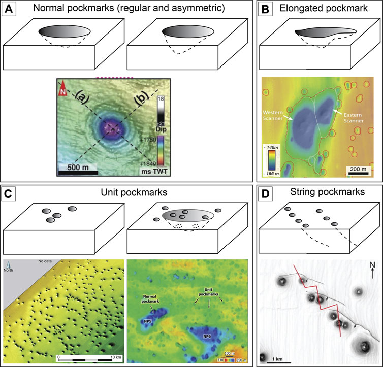
FIGURE 1. The main classes of pockmarks are modified from Hovland et al. (2002). (A) Normal pockmarks, including regular and asymmetric shapes, and a top view of a normal pockmark (Ho et al., 2018); (B) top view of an elongated pockmark (Gafeira et al., 2018); (C) perspective view of unit pockmarks, with and without a “parental” normal pockmark (de Mahiques et al., 2017; Tasianas et al., 2018); and (D) top view of string pockmarks (Pilcher and Argent, 2007).
Paleo-pockmarks and present-day pockmarks have been found in New Zealand both in the North Island and South Island regions (e.g., Pickrill, 1993; Chenrai and Huuse, 2017; Morley et al., 2017; Klaucke et al., 2018; Waghorn et al., 2018; Watson et al., 2020). Numerous paleo-pockmarks are shown in the GSB3D seismic reflection data, from the GSB of the South Island (Figure 2), which are associated with polygonal fault systems (Morley et al., 2017; Li et al., 2020; Jitmahantakul et al., 2020). Although petroleum fields in the GSB are not considered economically viable, they are still attractive and have potential for further exploration (Uruski et al., 2007; Uruski, 2010). This study may also be useful in other basins worldwide where current/future work might encounter similar fluid flow features. For example, a hydrocarbon-related pockmark can be used to indicate petroleum generation and maturation in a sedimentary basin. Therefore, investigating fluid migration and the timing of petroleum formation is key to further our understanding of the petroleum plumbing system and large-scale fluid pathway of the basin. The paleo-pockmarks observed within the Paleocene to Eocene fine-grained sedimentary successions can be used to shed light on fluid expulsion at the seabed during Eocene time (Figure 3). Additionally, analysis of seabed-sediment remobilization and fluid flow in ancient sediment sinks, such as pockmarks in deep marine depositional systems, is more challenging than in modern deep marine systems. Morley et al. (2017) suggested that the Middle Eocene paleo-pockmarks and the “honeycomb structure” in this basin are related to opal-A/CT transformation, which is characterised by a high amplitude reflection. The uncertainty about the proposed opal-A/CT transformation-related pockmarks comes from lacking adequate data to constrain the lithology of the sedimentary succession, lacking depositional environment interpretation, and lacking temperature calculation at the opal-A/CT transformation interval in their study. Moreover, Omosanya and Harishidayat (2019) and Jitmahantakul et al. (2020) demonstrated that there are the Eocene clinoform reflections beneath the paleo-pockmark interval. Recent publications and seismic interpretation studies have also demonstrated a geomorphic analysis and characteristic description of pockmarks that can be used to compare and understand the mechanisms of pockmark formation in the GSB (e.g., Andresen, 2012; Gay et al., 2012; Rollet et al., 2012; Serié et al., 2012; Krabbenhoeft et al., 2013; Chenrai and Huuse, 2017; Jatiault et al., 2019). Thus, this study aims to describe and identify the characteristics of the Middle Eocene paleo-pockmarks in the GSB, New Zealand, using the GSB3D seismic data in order to propose a hypothesis for the genesis of the paleo-pockmarks in the basin.
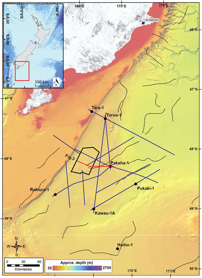
FIGURE 2. Location map of the Great South Basin and study area. The GSB3D seismic survey is highlighted as a black polygon, and the two-dimensional seismic lines are highlighted as blue lines. The red line represents a regional seismic profile in Figure 3. The thin black lines represent tectonic faults in the basin. Well locations are highlighted as black dots.
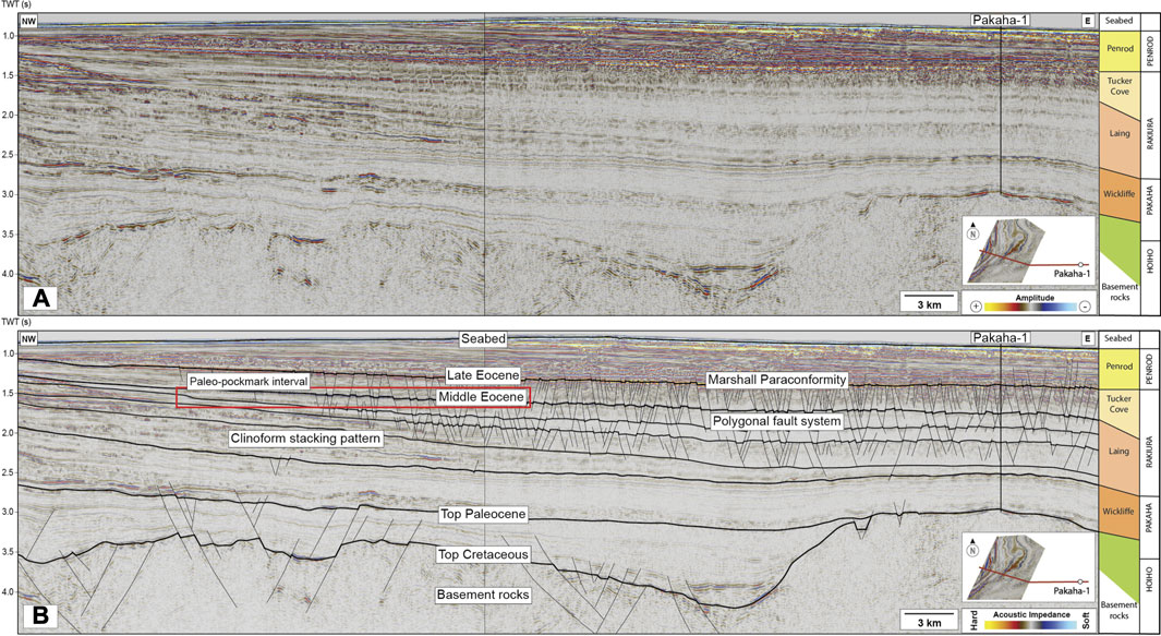
FIGURE 3. Regional seismic line shows the seismo-stratigraphy and age correlation of the study area. The stratigraphic units are correlated from 2D seismic data and the Pakaha-1 well located outside the 3D seismic survey. The paleo-pockmarks are highlighted in the red rectangle and restricted to the Middle Eocene mudstone succession of the Laing Formation above a clinoform stacking pattern. See seismic profile location in Figure 2.
The GSB lies off the southern coast of the South Island of New Zealand in water depths of 300–600 m (Figure 1). The basin consists of numerous sub-basins formed as a complex intra-continental rift of eastern Gondwana at approximately 105–100 Ma with grabens and half-grabens (Cook et al., 1998). The basement rocks include silicic-to-intermediate plutonics and metasedimentary rocks of about 92 Ma (Beggs, 1990). The stratigraphic framework of the GSB is based on (Constable et al., 2013; Figure 4).
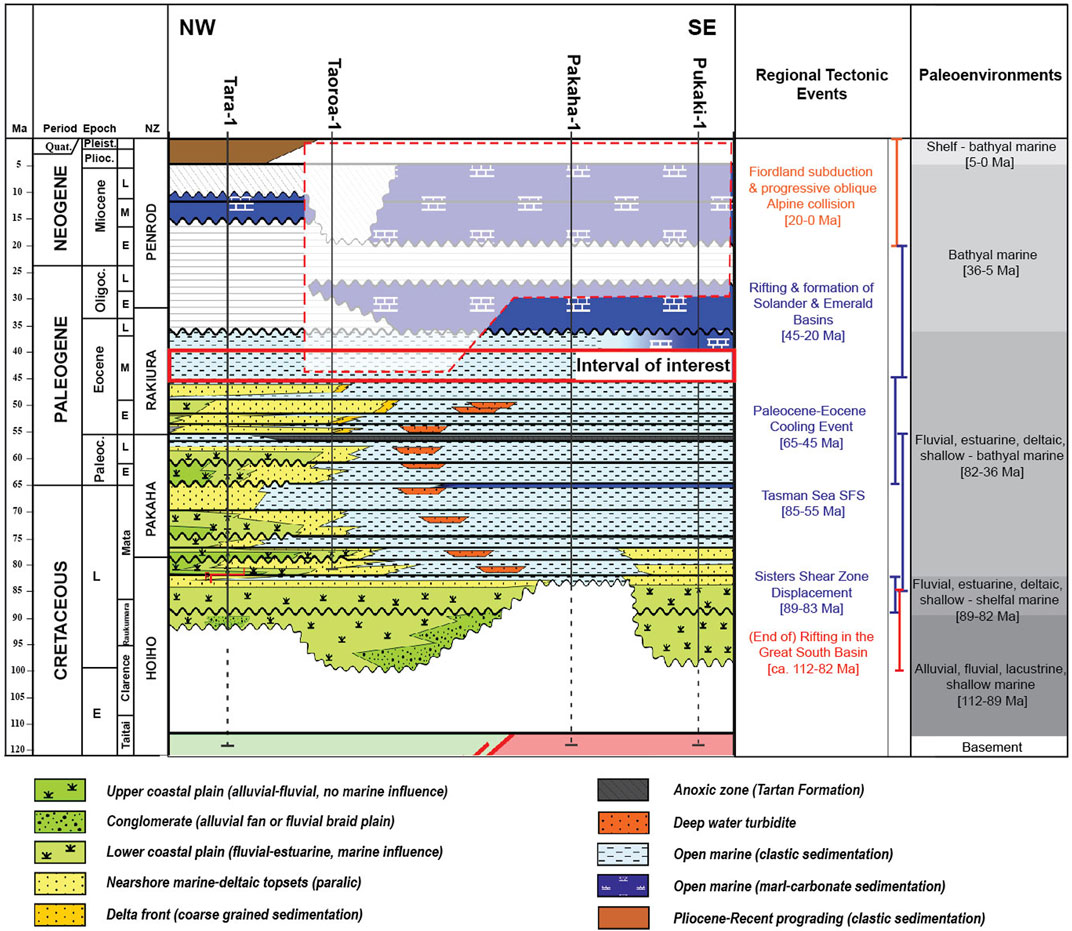
FIGURE 4. Stratigraphic framework of the Great South Basin including paleoenvironments and tectonic events. The red rectangle highlights the Laing Formation which is the paleo-pockmark interval. Compiled and modified from Constable et al. (2013).
The oldest known sedimentary sequence in the basin is the Hoiho Group, which consists of sandstones, shales, conglomerates, and coals during the Late Cretaceous (Cook et al., 1998). After the rifting phase, the Hoiho Group was deposited in a series of normal faulted depressions and sub-basins resulting in the deposition of fluvial and coal measure facies from braided floodplain and lacustrine environments (Meadows, 2009). The geochemistry of condensate in the Kawau–1, and oil shows in Kawau–1A and Toroa–1, suggest that mid-Cretaceous coaly facies are the main source rocks in the GSB (Killops et al., 1997; Sahoo et al., 2014). The Pakaha Group of Late Cretaceous to Paleocene sediments is characterised by widespread marine facies followed by shallowing to coastal environments during the Paleocene. The Pakaha Group is divided into the Kawau Sandstone, the Wickliffe Formation, and the Taratu Formation. The Kawau Formation is characterised by quartzose terrestrial sediments, which are the result of the increasing rate of subsidence from the intra-continental rifting to the seafloor spreading tectonic stage (Beggs, 1993). The Kawau Formation has high potential permeability and flow rates, and is a suitable reservoir for oil and gas migrating upwards from the underlying coal measures (Killops et al., 1997). The Wickliffe Formation is marked by unconformities at both the base and the top and consists of soft to firm, fissile, light grey shales and clays with subordinate darker brown shale (Cook et al., 1998; Meadows, 2009). During the Late Paleocene with restricted marine circulation, the Taratu Formation with organic–rich shales was deposited in the north-western portions of the basin, and this Formation is the most oil-prone (Cook et al., 1998; 1999).
The Rakiura Group was deposited during the Eocene epoch and is divided into the Laing and Tucker Cove limestone Formations. The Rakiura Group is interpreted to represent slope-to-basin floor submarine fans, bathyal carbonates and clastics, and submarine canyon deposits (Meadows, 2009). The top of the group is marked by a regional unconformity close to the present shelf edge that separates the Rakiura Group from the Penrod Group sediments. The Laing Formation was deposited in a shelf to the upper bathyal environment and extends over most of the basin with a thickness of approximately 2 km in some places (Schiøler et al., 2010; Viskovic, 2011). During the Early Eocene, a thick prograding clastic wedge was deposited in the northwest of the basin, while upper bathyal depth deposition occurred to the east (Viskovic, 2011). By the end of the Eocene, relative sea level rise in the basin resulted in upper bathyal conditions in the north-western portion of the basin and mid-bathyal conditions to the east (Cook et al., 1999). The Laing Formation sedimentary successions were then overlain by the Tucker Cove Formation, which consists of soft to firm, white to light grey, fine-grained, foraminiferal limestone with chert nodules and traces of pyrite and glauconite (Beggs, 1993; Meadows, 2009).
The Penrod Group consists of mainly mid-Oligocene and younger carbonate sediments and is generally less than 500 m thick over most of the basin (Cook et al., 1999). The group has a complex internal structure caused by shelf effects, currents and changing tectonics (Viskovic, 2011). From the Oligocene to the present, tectonic activity has progressively increased in New Zealand (Nicol et al., 2007; McArthur et al., 2020). To the northeast of New Zealand, the Pacific plate is moving southwest and being subducted beneath the North Island. Within the South Island, the plate boundary transitions to dextral strike slip kinematics, moving to the western side of the island where the Australian plate then subducts beneath the Pacific plate (Carter and Norris, 1976; Lamb et al., 2016). The GSB is situated along the passive margin to the southeast of the South Island. The base of the Oligocene to recent sediments is marked by a significant change to more carbonate-rich sediments (chalks or foraminiferal oozes) in the southeast portions of the basin and an erosion surface along the north-western margin (Cook et al., 1999).
The data presented here are from the GSB3D seismic survey acquired by a joint venture of ExxonMobil New Zealand (Exploration) Limited and Todd Exploration Limited during 2007–2009 (Figure 2). The seismic volume covers a surface area of 1,344 km2 and is a full offset, post-stack, migrated volume, where acoustic impedance increases (“hard” reflections) are indicated by positive amplitudes (Hunt International Petroleum Company N.Z., 1977). The seismic data have a bin spacing of 12.5 × 25 m in crossline and inline directions, respectively. The seismic data are dominated by frequency of 40–60 Hz, resulting in a vertical resolution of about 8–12.5 m, using an average sediment velocity of 2.0 km/s for the Rakiura Formation (Hunt International Petroleum Company, N.Z, 1977). The horizontal resolution of about 16–25 m ensures confidence in the geomorphological interpretation of the paleo-pockmarks. The Pakaha-1 exploration well that was drilled adjacent to the 3D seismic survey was used to constrain the lithostratigraphy of the study area and correlate the information with 2D seismic sections (Hunt International Petroleum Companty, N.Z., 1977). Seismic volume attributes such as variance, 3D curvature dip, and consistent dip, were used to identify the morphology of the paleo-pockmarks in this study. The surface attribute root mean square (RMS) amplitude was chosen to show the distribution of the paleo-pockmarks. A set of horizons was interpreted over the 3D seismic data by calibrating the Pakaha-1 well as presented in Figure 3. Based on our observations and data from the Pakaha-1 well, the paleo-pockmark interval is dominated by claystone and shale at the lower and upper parts of the Laing Formation, respectively. However, it should be noted that the well is located approximately 30 km east of the paleo-pockmark interval.
In this study, the geometrical characteristics (shape and size) of the paleo-pockmarks are described from a selected area of approximately 5 km2. The selected area is picked within the paleo-pockmark interval in order to represent the different paleo-pockmark characteristics in each zone. Then, obvious paleo-pockmarks above seismic resolution inside the selected areas are measured for their characteristics.
Across the study area, numerous paleo-pockmarks are widespread laterally within basin floor deposits and are clearly displayed on the seismic time slice at 1,492 ms (TWT) (Figure 5). The paleo-pockmark interval is interpreted as the top of the Laing Formation by correlation with the 2D seismic line and the Pakaha-1 well (Figure 3). The RMS amplitude attribute is used to image the depositional element at the paleo-pockmark interval and shows a fan-shaped body with a high amplitude anomaly associated with the paleo-pockmarks from the proximal to distal fan as presented in Figure 6. Thus, the fan-shaped body, widening to the NE with an apex in the SW, is divided into three major zones, proximal, middle, and distal fans. Seismically, the fan-shaped body is bounded by onlapping or downlapping reflections with a flat reflection within the sedimentary package. Internal reflections are characterised by high to low, chaotic, and semi-continuous reflections. The fan-shaped body is lensoidal in the cross section with a maximum thickness of about 60 m and is an irregular ovoid in the map view (Figures 6, 7). The fan-shaped body preferentially dips to the NE direction and covers an area of more than 100 km2. Thus, this fan-shaped body is interpreted as a lobe complex based on Prélat et al. (2009). To the west, an interpreted fine-grained interval with polygonal faults onlaps against older low-angle clinoform reflections interpreted to be the progradation system at around 1.7–1.8 km beneath the paleo-pockmark interval (Figure 7). The RMS amplitude map presents an increasing number of paleo-pockmarks from the distal to proximal fan (Figure 6). Three areas, one within each the three major zones (A, B, and C) of the fan shape, are chosen to study the paleo-pockmark morphology and density (Figure 6). Variance and consistent dip attributes are used to image the characteristics of paleo-pockmarks in each zone. The variance attribute is used to measure the similarity of seismic reflections, while consistent dip attribute is used to calculate the dip angle of the paleo-pockmark craters (Figure 6).
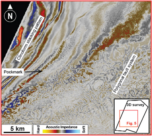
FIGURE 5. Seismic time slice through 1,492 ms shows a wide area of paleo-pockmarks within the Middle Eocene mudstone succession.
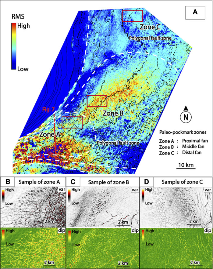
FIGURE 6. (A) RMS amplitude attribute map extracted from the 0–50 ms (TWT) interval below the top surface of the Laing Formation. Paleo-pockmarks are distributed in a fan-shaped body. The variance (var) and consistent dip (dip) images show the samples of the paleo-pockmark from zones A, B, and C. (B–D) Zoom-in images from the selected locations show the geometric measurements which are indicated by red rectangles. White dashed lines are the boundary of the zones.
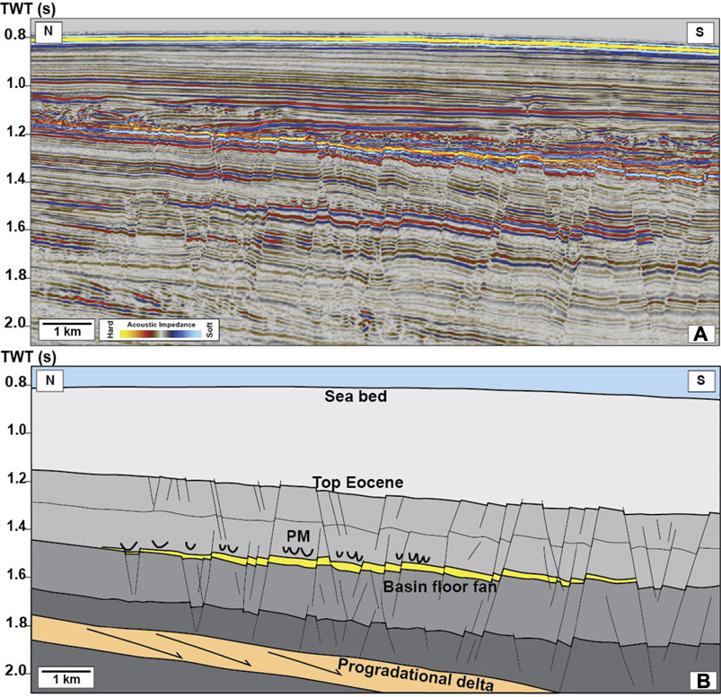
FIGURE 7. (A) Un-interpreted and (B) interpreted 3D seismic profiles show paleo-pockmarks (PM) above a basin floor fan and polygonal faults in very fine-grained sedimentary successions above a progradational delta. See seismic profile location in Figure 6.
Size measurements are described in terms of the width and depth of the paleo-pockmarks, where the width or diameter is a measurement from the longest axis of the pockmark between pockmark edges, while the paleo-pockmark depth is the measurement in a vertical direction from the pockmark crater to the pockmark base (Figure 8). In total, 94 paleo-pockmark samples were measured from zones A, B, and C for the geometrical characteristics (see Figure 6 for locations). Characteristics of the paleo-pockmarks of each zone are described in the next sections and summarised in Table 1. The paleo-pockmarks were classified as “normal pockmarks” based on Hovland et al. (2002) with a sub-round to round shape on the top view and a V- to U-shape in the vertical section (Figures 9–11). Their sizes mainly ranged from 131 to 481 m in diameter and 15–45 ms (TWT) in depth. The smallest paleo-pockmark was found in zone B with a diameter and depth of approximately 131 m and 16 ms (TWT), respectively (Table 1). The largest paleo-pockmark was found in zone A with a diameter and depth of approximately 481 m and 15 ms (TWT), respectively (Table 1). However, it should be noted that the geometry of the paleo-pockmarks is measured from compacted sedimentary strata. Thus, the paleo-pockmark depth and wall would have been deeper and steeper than the present day. There are no acoustic (amplitude) anomalies nor signs of vertical seismic discontinuity beneath the paleo-pockmarks which could indicate a fluid origin from below the paleo-pockmark interval. The paleo-pockmarks are usually associated with a high amplitude anomaly (hard reflection) within the paleo-pockmark crater, especially in zone A.

FIGURE 8. Characteristics of a paleo-pockmark showing the (A) top view and (B) side view. The paleo-pockmark width and depth are measured in seismic section. Width is measured from the longest axis of pockmark between pockmark edges (A-A′), while depth is measured in a vertical direction from pockmark crater to pockmark base.
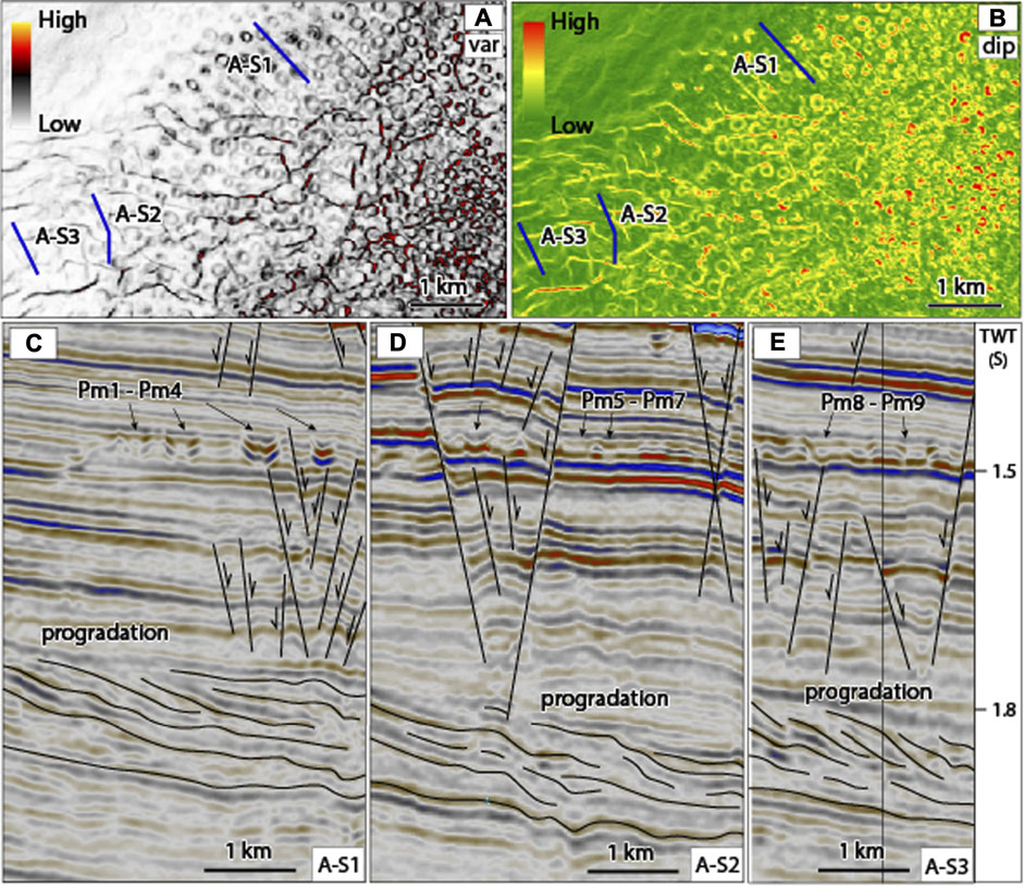
FIGURE 9. (A) The variance map shows sub-round to round-shaped pockmarks on the top view with medium to high discontinuity values (0.5–0.8), while (B) the consistent dip map shows slope angles of paleo-pockmark walls between 7 and 15° (medium to high value). (C–E) Seismic sections A-S1 to A-S3 show the shape of nine paleo-pockmarks (Pm1—Pm9) in profile view. Pm1 and Pm2 are V-shaped pockmarks, while Pm3 to Pm9 are U-shaped pockmarks. Their size ranges from 204 to 382 m width and 19–45 ms (TWT) depth.
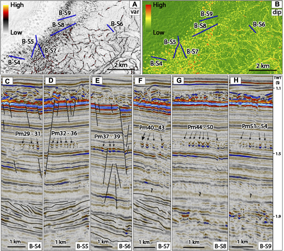
FIGURE 10. (A) The variance map shows sub-round to round-shaped pockmarks on the top view with low to high discontinuity values (0.5–0.8), while (B) the consistent dip map shows slope angles of paleo-pockmark walls between 4 and 15° (low to high value). (C–H) Seismic sections B-S4 to B-S9 show the shape of 26 paleo-pockmarks (Pm29—Pm54) in profile view, as V- and U-shaped pockmarks with a size range from 131 to 350 m width and 16–45 ms (TWT) depth. The progradation seismic pattern of clastic sediments is observed beneath the paleo-pockmark interval.
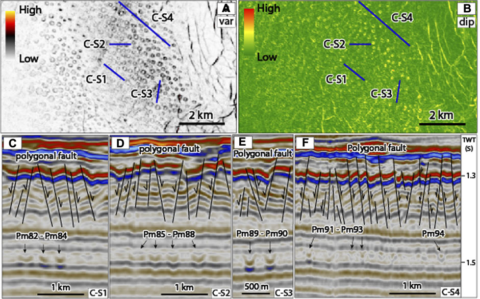
FIGURE 11. (A) The variance map showing sub-round to round-shaped pockmarks on the top view with low to medium values (0.3–0.5) of discontinuity, while (B) the consistent dip map shows slope angles of paleo-pockmark walls between 4 and 7° (low to medium value). (C–F) Seismic sections C-S1 to C-S4 show the shape of 13 paleo-pockmarks (Pm82—Pm94) in profile view, as V- and U-shaped pockmarks with a size range from 163 to 281 m width and 16–37 ms (TWT) depth. The polygonal fault system is observed over the paleo-pockmark interval.
The variance attribute map displays the sub-round to round paleo-pockmarks in shapes from the top view (Figure 9). In the profile view, U-shaped paleo-pockmarks were commonly observed (Figure 9). Slope angles of the paleo-pockmark walls are between 7 and 15°, as seen in the consistent dip attribute map. The paleo-pockmarks in zone A have a size range of 204–481 m diameter and 15–45 ms (TWT) depth. In addition, the paleo-pockmarks in zone A are larger than those in the other zones (Table 1).
The variance attribute map showed a common sub-round paleo-pockmark from the top view (Figure 10). In the profile view, U-shaped paleo-pockmarks were observed in the seismic sections. Slope angles of the paleo-pockmark walls are between 4 and 15°, as observed in the consistent dip attribute map. The size of the paleo-pockmarks ranges from 131 to 350 m diameter and 15–45 ms (TWT) depth. The smallest paleo-pockmark is Pm37 with a 131 m diameter and 16 ms (TWT) depth and is located in the central part of this zone.
The variance attribute map displayed sub-round to round paleo-pockmarks from the top view, while V- and U-shaped paleo-pockmarks (Pm82 to Pm94) were observed in the seismic sections (Figure 11). Slope angles of the paleo-pockmark walls are between 4 and 7°, as observed in the consistent dip attribute map. The size of the paleo-pockmarks ranges from 163 to 281 m diameter and 16–37 ms (TWT) depth. Generally, the paleo-pockmarks in this zone show a low relief pockmark. Due to their low relief and seismic resolution, internal structure is difficult to observe within the paleo-pockmarks. The paleo-pockmarks in zone C are usually observed below the polygonal fault interval.
Curvature dip attribute describes how much the curve deviates at the edge and base of the paleo-pockmarks from a horizontal plane. This seismic attribute displays the paleo-pockmark shapes from the top view (Figure 12). The blue colour (positive curvature) and red colour (negative curvature) are identified as the edge and base of the paleo-pockmark, respectively (Figure 12F). The paleo-pockmark density, estimated by counting the number of paleo-pockmarks in a chosen 5 km2 area (Figure 12D), was 32, 67, and 21 pockmarks/km2 in zones A, B, and C, respectively.
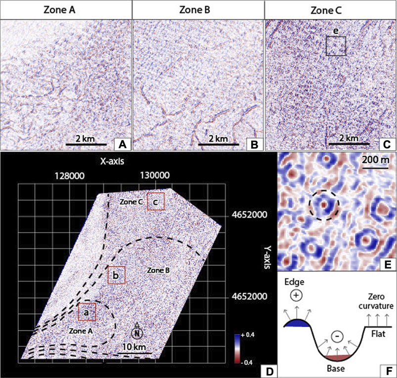
FIGURE 12. Characteristics of paleo-pockmarks from the curvature dip map for zones (A) A, (B) B, and (C) C (locations in the red rectangles). Black-dashed lines are the boundaries of the three paleo-pockmark zones (D). Characteristics of paleo-pockmarks are shown in a dashed circle (blue colour is pockmark edge, and red colour is pockmark base) (E, F).
In general, the paleo-pockmark characteristics in the GSB show similar shapes, but different sizes. In total, 94 paleo-pockmarks were selected to represent their shapes and sizes in both top and profile views. The selected paleo-pockmarks from zones A, B, and C showed the same characteristics of round to sub-round shapes in the top view and V- to U-shapes in the seismic profiles. However, the sizes of the paleo-pockmarks were diverse in each zone (Table 1). Thus, the size of the paleo-pockmarks in this area fits within the normal pockmark class of 131–481 m in diameter and up to 45 m depth (Hovland et al., 2002). A normal pockmark can be used as an indicator of both porewater and gas expulsions, and is usually found in basins that have low-energy currents (e.g., Nickel et al., 2012; Chenrai and Huuse, 2017; Mazzini et al., 2017). The size (diameter and depth) of the paleo-pockmarks in the GSB was plotted along with those previously reported around the world based on Pilcher and Argent (2007; Figure 13), and revealed that the sizes of the paleo-pockmarks in the GSB fall within an expected range. Moreover, the density of normal pockmarks can help to interpret the fluid source in the sedimentary basin-fill. For example, high-density normal pockmarks are mostly found in a large gas field, such as the Barents Sea (Mazzini et al., 2017) and the North Sea (Nickel et al., 2012).
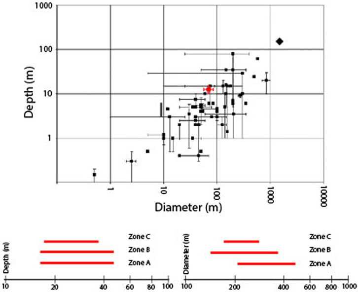
FIGURE 13. Graph illustrates the pockmark geometry of previously studied pockmarks from 57 published sites, complied by Pilcher and Argent (2007) in comparison with this study at the GSB. The X and Y scales are logarithmic. The paleo-pockmark geometry of this study is presented by a red cross-hair by applying a velocity of 2.0 km/s. Pilcher and Argent (2007) used single points to represent either measurements of single pockmarks or average measurements and used error bars to represent the range of sizes in a pockmark field.
In this section, the comparative density of paleo-pockmarks in the study area was evaluated for zones A (proximal fan), B (middle fan), and C (distal fan). The paleo-pockmark density in zone B is the highest density zone, while zone C is the lowest density zone (Table 1). It should be noted that the paleo-pockmark density in this study is calculated by counting the number of the paleo-pockmarks within the selected area (Figure 6). With respect to the paleo-pockmark distribution in each location, the clinoform facies beneath the paleo-pockmark interval possibly indicates a basin margin environment deposited from slope to basin (from southwest to northeast direction). Seismically, onlap reflections are observed on top of the clinoform facies indicating a transgressive marine system providing thick mudstone layers (up to 1,000 m) in the basin coinciding with previous studies (e.g., Schiøler et al., 2010). Omosanya and Harishidayat (2019) studied Eocene deltaic clinoforms in this area and observed distributary channels and mouth-bars within the clinoform reflections. These distributary channels are interpreted as sand-filled channels giving sand-prone deposits at proximal delta (Omosanya and Harishidayat, 2019; Jitmahantakul et al., 2020).
The basin floor fan deposits beneath the paleo-pockmarks area at zone A (proximal fan) and zone B (middle fan) may act as a pathway to bring fluids from the surrounding layers to the paleo-pockmark layers creating the paleo-pockmarks during the Middle Eocene. Furthermore, the paleo-pockmark sizes in zone A are larger than those in zone B and zone C (Table 1). It is possible that the size and density of the paleo-pockmarks in this area are controlled by lithology or fluid pathway. Based on the fact that fluids will migrate through coarse-grained sediments more readily than fine-grained sediments, the paleo-pockmarks at the proximal fan are usually larger than those in the distal fan.
The possible fluid sources (pore water, hydrothermal fluid and hydrocarbon fluid) that could contribute to the formation of the paleo-pockmarks in the study area are discussed in this section. These fluid types are commonly found and related to fluid flow process in offshore areas worldwide (Pickrill, 1993; Dimitrov and Woodside, 2003; Cartwright et al., 2004; Hübscher and Borowski, 2006; Chenrai and Huuse, 2017; Tasianas et al., 2018).
Pore water is water that is trapped between the sediment grains during or after sediment deposition. Generally, sediments are believed to be fully saturated in submarine environments at equilibrium stage, and pore water remains in pore spaces. Any reduction in pore spaces during burial, and compaction during diagenesis may cause the pore water to migrate laterally and upwards according to the hydraulic head. Thus, pore water is forced to migrate upwards until it is expelled at the seabed, displacing sediment and forming pockmarks. Pore water is one of the important fluid sources for pockmark generation (e.g., King and Maclean, 1970; Harrington, 1985; Chenrai and Huuse, 2017). However, sediment compaction during diagenesis is not the only trigger for pore water escaping from sedimentary formation, as the escape of pore water can also be associated with other conditions such as earthquakes (Hovland, 2002), sea level change (Luo et al., 2014), and rapid sediment loading (Chenrai and Huuse, 2017).
In addition, pore water is relatively high within fine-grained sediments such as clay and silt compared to coarser sediments (Harrington, 1985). Based on the Pakaha-1 and Rakiura-1 wells, the paleo-pockmarks in the study area occurred on the surface of the Laing Formation which is dominated by mudstone and claystone. If the sedimentary layer in this formation is saturated with water, then pore water is potentially one of the fluid sources responsible for the paleo-pockmark formation in the study area. However, no seismic characteristics of fluid pathways, such as fluid pipes and chimneys, to the paleo-pockmarks are observed in the 3D seismic data. Thus, it is unclear if pore water from the compacting mudstone strata could have contributed to the paleo-pockmarks, and we were unable to either accept or refute pore water as a possible fluid source. In addition, if pore water driven by mudstone compaction occurred and migrated into the paleo-pockmark layer, it would increase the pore fluid pressure within the layer leading to fluid expulsion resulting in the formation of paleo-pockmarks.
Hydrothermal activity is the process of heated subsurface water circulation (Colín-García et al., 2016). Subsurface water is heated near magma and volcanic rocks (batholiths, sills, and dykes) with temperatures up to 1,200°C (Judd and Hovland, 2009). Hydrothermal activity occurs in both the oceanic and continental crust, including mid-oceanic ridges, back-arc basins, and on submarine volcanic arcs (Norton, 1984; Hovland et al., 2005). Hydrothermal venting is one of the main processes that can form pockmarks on the seabed (Judd and Hovland, 2009). Volcanic activity was widespread in the Late Cretaceous and Cenozoic in New Zealand, forming volcanoes and igneous intrusions buried in sedimentary basins, including the Canterbury basin and GSB. Volcanoes and igneous intrusions have been widely recognised and mostly found within the Canterbury basin (e.g., Magee et al., 2019; Barrier et al., 2021). The GSB is located relatively close (∼200 km) to the Alpine Fault, however the basin is considered to be relatively tectonically stable, and not influenced by back-arc extension or Alpine deformation (Phillips and Magee, 2020). However, volcanoes and igneous intrusions can be observed from 2D seismic lines outside the GSB3D seismic volume. Although hydrothermal fluids have been mentioned as a fluid source responsible for creating pockmarks in Lake Rotoiti, New Zealand (Pickrill, 1993), hydrothermal fluids are not considered as a fluid source for the paleo-pockmarks in this study area because the paleo-pockmark field is closely linked with the occurrence of a slope-to-basin fan rather than any igneous phenomena. Also, no seismic characteristics of volcanic activities are found in the study area, and so there may have been no heat source from hydrothermal activity in this area. The standard temperature of the sedimentary formation is insufficient for formation of hydrothermal fluid. If hydrothermal fluids had been involved in fluid expulsion on the Middle Eocene seabed, the paleo-pockmarks should be linked with igneous structures, which should be clearly identified in the seismic data.
The large distribution area of the paleo-pockmarks in this study suggests that fluids were also sourced from across a large area. The vitrinite reflectance of about 0.45% indicates a thermally immature source rock at a depth of about 3 km in Paleocene successions (Hunt International Petroleum Company, N.Z., 1977). Thus, only the Cretaceous source rock is thermally mature, while the younger Paleocene source rock is in an immature stage (Shalaby et al., 2020). Cretaceous source rocks at the depocenter of the GSB are predicted to have been expelled in the early Eocene (Kroeger and Funnell, 2012). Methane-dominated dry gas of possible biogenic origin is often documented in offshore wells at depths above 1,200 m (Hunt International Petroleum Company, N.Z., 1977). However, if the thermogenic hydrocarbons from the Cretaceous source rocks have been generated, it is difficult for hydrocarbon fluid to migrate vertically into the Middle Eocene seabed during the paleo-pockmark formation. Seismically, there is no clear evidence of gas anomalies, such as gas chimneys, fluid pipes, or acoustic blanking underneath the paleo-pockmarks. Thus, local deep thermogenic hydrocarbon fluids are of lesser importance in forming the Middle Eocene paleo-pockmark. Biogenic methane can be generated at 0–80°C temperature with a low level of organic matter (total organic carbon, less than 0.5%) and low porosity/permeability (Rice and Claypool, 1981; Rice, 1992). Biogenic methane can be produced by several processes, but carbon dioxide reduction and acetate fermentation are very common within sedimentary successions (Judd and Hovland, 2007; Katz, 2011). If biogenic methane was generated during the Middle Eocene, pore pressure within the sedimentary formation will be increased by adding methane fluid in the pore space, leading to the formation of paleo-pockmarks. Therefore, we propose that the fluid origin that created this paleo-pockmark field originated from biogenic gas. During the Middle Eocene, the Laing Formation was formed by deposition of muds and clays of the bathyal environment. This deposition may have involved organic-rich sediments that could provide or generate biogenic gas associated with microbial activity within the sedimentary successions. Biogenic gas from the microbial consumption of organic matter has previously been implicated in pockmark formation (e.g., Hovland et al., 2002; Judd and Hovland, 2007; Krämer et al., 2017).
The wide distribution of the low-relief pockmark in the study area, especially in zone C, is believed to be associated with a low fluid flux from the shallow subsurface. Most previous pockmark models suggested that pockmarks are formed by catastrophic fluid (mostly gas) expulsions (e.g., Hovland and Judd, 1988). However, the methane seep model of biogenic gas from a shallow subsurface does not require an overpressure condition to create a pockmark (Agirrezabala et al., 2013). This model can be used to support the Middle Eocene paleo-pockmark formation in the GSB. Thus, biogenic gas is a potential main fluid source for the paleo-pockmarks in the GSB.
Taking the main potential fluid origin of the Middle Eocene paleo-pockmarks in the GSB to be microbial methane produced during basin burial and subsidence, a model for the proposed formation of the paleo-pockmarks in the GSB is presented schematically in Figure 14 and outlined below, based upon microbial methane production at a low temperature (<60°C) condition near the Middle Eocene seabed.
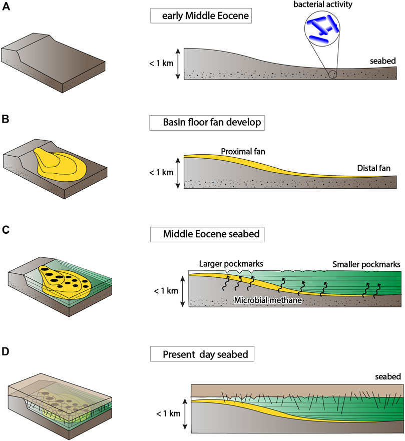
FIGURE 14. Schematic evolutionary cartoon of the paleo-pockmark formation in the Great South Basin based on the occurrence of microbial methane from the early Middle Eocene to present day. (A) Initial deposition of sedimentary formation and microbial methane generation during the early Middle Eocene. (B) Basin floor fan development on top of the initial deposition. (C) Transgressive marine mudstones continue to deposit providing a seal on top of the fan and creating a new seabed. Substantial increase in pore pressure due to microbial migration eventually leads to expulsion of microbial methane on the seabed. (D) Sea-level rise led to younger mud and carbonate sediments being deposited onto the Laing Formation and burying the paleo-pockmarks.
Fine-grained sediment and organic matter were deposited on the seabed in the early stages. Bacteria accumulated and decomposed organic matter in the sediments, producing methane by carbon dioxide reduction and fermentation in anoxic conditions (Judd and Hovland, 2007; Katz, 2011).
Coarse- and fine-grained sediments began to be deposited in the slope area and formed the basin floor fan orientated from a southwest to northeast direction, possibly during the mid-Middle Eocene. Coarse-grained sediments were transported and deposited when the energy decreased at the proximal fan, while fine-grained sediments were transported to the distal fan (e.g., Hawie et al., 2019).
Transgressive marine mudstones of the Laing Formation overlie the basin floor fan. The thick bed of marine mudstone generated an overburden pressure in the basin floor fan package, which forced fluids to migrate upwards into the paleo-pockmark interval. Microbial methane from the mudstone strata below the paleo-pockmark interval could laterally and vertically migrate through the permeable layers within the basin floor fan until, eventually, the pore pressure exceeded the fracture gradient of the seal leading to the microbial methane escaping onto the paleo-seabed. Followed by fine-grained sediment compaction, the polygonal fault system then developed on the upper part of the Laing Formation in the study area.
Sea-level rise led to mud and carbonate sediments of the Tucker Cover Formation and Penrod Group to deposit above the Laing Formation, and to bury the Middle Eocene paleo-pockmarks with these younger mud and carbonate sediments.
Fluid flow features recording fluid expulsion at the paleo-seabed are manifested in the Great South Basin as paleo-pockmarks that formed during the Middle Eocene. The paleo-pockmarks are observed along a trend that can be related to the distribution of underlying basin floor fan sediments in the ancient sediment-sink area. The evidence presented here shows that fluid flow activity in this basin has been active since at least the Middle Eocene. The analysis of the seismic data covering this paleo-pockmark field allowed the characterisation of the paleo-pockmark zone into three zones distributed in mudstones above basin floor fan deposits. The possible origin of fluids in this scenario is likely to be biogenic methane, suggesting that not all pockmarks should be used as indicators of thermogenic hydrocarbon expulsion. The progradational seismic pattern of clastic sediments beneath the paleo-pockmark interval possibly enhanced the fluid migration through the permeable layers. The proposed model may help to explain pockmark formation associated with basin floor fan deposits and inform future studies of fluid migration and expulsion within sedimentary basins.
The original contributions presented in the study are included in the article/supplementary material, further inquiries can be directed to the corresponding author.
All authors actively contributed to various parts of the manuscript and agreed with its contents. The data analysis and interpretation was conducted by AK and PC. The manuscript was also developed, written and revised by all authors.
This work was financially supported by the Research Grant for New Scholar Ratchadaphisek Somphot Endowment Fund, Chulalongkorn University.
The authors declare that the research was conducted in the absence of any commercial or financial relationships that could be construed as a potential conflict of interest.
All claims expressed in this article are solely those of the authors and do not necessarily represent those of their affiliated organizations, or those of the publisher, the editors and the reviewers. Any product that may be evaluated in this article, or claim that may be made by its manufacturer, is not guaranteed or endorsed by the publisher.
Schlumberger and IHS generously supplied Petrel and Kingdom licenses to Chulalongkorn University. The data were released by the New Zealand government. Reviewers are thanked for their useful and constructive comments. Specialty chief editor, David Mark Hodgson is thanked for valuable comments and suggestions. The authors thank the Office of Research Affairs, Chulalongkorn University, for assistance during manuscript preparation.
Agirrezabala, L. M., Kiel, S., Blumenberg, M., Schäfer, N., and Reitner, J. (2013). Outcrop Analogues of Pockmarks and Associated Methane-Seep Carbonates: a Case Study from the Lower Cretaceous (Albian) of the Basque-Cantabrian Basin, Western Pyrenees. Palaeogeogr. Palaeoclimatol. Palaeoecol. 390, 94–115. doi:10.1016/j.palaeo.2012.11.020
Andresen, K. J. (2012). Fluid Flow Features in Hydrocarbon Plumbing Systems: What Do They Tell Us about the basin Evolution? Mar. Geology. 332-334, 89–108. doi:10.1016/j.margeo.2012.07.006
Andresen, K. J., and Huuse, M. (2011). 'Bulls-eye' Pockmarks and Polygonal Faulting in the Lower Congo Basin: Relative Timing and Implications for Fluid Expulsion during Shallow Burial. Mar. Geology. 279, 111–127. doi:10.1016/j.margeo.2010.10.016
Andresen, K. J., Huuse, M., and Clausen, O. R. (2008). Morphology and Distribution of Oligocene and Miocene Pockmarks in the Danish North Sea - Implications for Bottom Current Activity and Fluid Migration. Basin Res. 20 (3), 445–466. doi:10.1111/j.1365-2117.2008.00362.x
Anka, Z., Ondrak, R., Kowitz, A., and Schødt, N. (2013). Identification and Numerical Modelling of Hydrocarbon Leakage in the Lower Congo Basin: Implications on the Genesis of Km-wide Seafloor Mounded Structures. Tectonophysics 604, 153–171. doi:10.1016/j.tecto.2012.11.020
Barrier, A., Bischoff, A., Nicol, A., Browne, G. H., and Bassett, K. N. (2021). Relationships Between Volcanism and Plate Tectonics: A Case-Study from the Canterbury Basin, New Zealand. Mar. Geol. 433, 106397. doi:10.1016/j.margeo.2020.106397
Beggs, J. M. (1993). Depositional and Tectonic History of the Great South Basin. Sedim. Basins World 2, 365–373.
Beggs, J. M. (1990). “Seismic Stratigraphy of the Plio-Pleistocene Giant Foresets, Western Platform, Taranaki Basin,” in New Zealand Oil Exploration Conference Proceedings (Queenstown: Ministry of Commerce), 201–207.
Berndt, C. (2005). Focused Fluid Flow in Passive continental Margins. Phil. Trans. R. Soc. A. 363, 2855–2871. doi:10.1098/rsta.2005.1666
Carter, R. M., and Norris, R. J. (1976). Cainozoic History of Southern New Zealand: an accord between Geological Observations and Plate-Tectonic Predictions. Earth Planet. Sci. Lett. 31, 85–94. doi:10.1016/0012-821x(76)90099-6
Cartwright, J. (2007). The Impact of 3D Seismic Data on the Understanding of Compaction, Fluid Flow and Diagenesis in Sedimentary Basins. J. Geol. Soc. 164, 881–893. doi:10.1144/0016-76492006-143
Cartwright, J., Wattrus, N., Rausch, D., and Bolton, A. (2004). Recognition of an Early Holocene Polygonal Fault System in Lake Superior: Implications for the Compaction of fine-grained Sediments. Geol. 32 (3), 253–256. doi:10.1130/g20121.1
Chen, J., Song, H., Guan, Y., Yang, S., Pinheiro, L. M., Bai, Y., et al. (2015). Morphologies, Classification and Genesis of Pockmarks, Mud Volcanoes and Associated Fluid Escape Features in the Northern Zhongjiannan Basin, South China Sea. Deep Sea Res. Part Topical Stud. Oceanography 122, 106–117. doi:10.1016/j.dsr2.2015.11.007
Chenrai, P., and Huuse, M. (2017). Pockmark Formation by Porewater Expulsion during Rapid Progradation in the Offshore Taranaki Basin, New Zealand. Mar. Pet. Geology. 82, 399–413. doi:10.1016/j.marpetgeo.2017.02.017
Colín-García, M., Heredia, A., Cordero, G., Camprubí, A., Negrón-Mendoza, A., Ortega-Gutiérrez, F., et al. (2016). Hydrothermal Vents and Prebiotic Chemistry: a Review. Bsgm 68, 599–620. doi:10.18268/bsgm2016v68n3a13
Constable, R. M., Langdale, S., and Allan, T. M. H. (2013). Development of a Sequence Stratigraphic Framework in the Great South Basin, In: Proceedings of New Zealand Petroleum Conference, Auckland, New Zealand, 1–21.
Cook, R. A., Sutherland, R., and Zhu, H. (1999). Cretaceous-Cenozoic Geology and Petroleum Systems of the Great South Basin. New Zealand: Institute of Geological & Nuclear Sciences.
Cook, R. A., Zhu, H., Sutherland, R., Killops, S., and Funnell, R. (1998). “Future Exploration of the Great South Basin,” in New Zealand's basins of opportunity: New Zealand Petroleum Conference: proceedings.
de Mahiques, M. M., Schattner, U., Lazar, M., Sumida, P. Y. G., and Souza, L. A. P. d. (2017). An Extensive Pockmark Field on the Upper Atlantic Margin of Southeast Brazil: Spatial Analysis and its Relationship with Salt Diapirism. Heliyon 3 (2), e00257. doi:10.1016/j.heliyon.2017.e00257
Dimitrov, L., and Woodside, J. (2003). Deep Sea Pockmark Environments in the Eastern Mediterranean. Mar. Geology. 195, 263–276. doi:10.1016/s0025-3227(02)00692-8
Donda, F., Forlin, E., Gordini, E., Panieri, G., Buenz, S., Volpi, V., et al. (2014). Deep-sourced Gas Seepage and Methane-Derived Carbonates in the Northern Adriatic Sea. Basin Res. 27, 531–545. doi:10.1111/bre.12087
Gafeira, J., Dolan, M., and Monteys, X. (2018). Geomorphometric Characterization of Pockmarks by Using a GIS-Based Semi-automated Toolbox. Geosciences 8 (5), 154. doi:10.3390/geosciences8050154
Gay, A., Lopez, M., Berndt, C., and Séranne, M. (2007). Geological Controls on Focused Fluid Flow Associated with Seafloor Seeps in the Lower Congo Basin. Mar. Geology. 244, 68–92. doi:10.1016/j.margeo.2007.06.003
Gay, A., Lopez, M., Cochonat, P., and Sermondadaz, G. (2004). Polygonal Faults-Furrows System Related to Early Stages of Compaction - Upper Miocene to Recent Sediments of the Lower Congo Basin. Basin Res. 16, 101–116. doi:10.1111/j.1365-2117.2003.00224.x
Gay, A., Mourgues, R., Berndt, C., Bureau, D., Planke, S., Laurent, D., et al. (2012). Anatomy of a Fluid Pipe in the Norway Basin: Initiation, Propagation and 3D Shape. Mar. Geology. 332-334, 75–88. doi:10.1016/j.margeo.2012.08.010
Harrington, P. K. (1985). Formation of Pockmarks by Pore-Water Escape. Geo-Marine Lett. 5, 193–197. doi:10.1007/bf02281638
Hawie, N., Covault, J. A., and Sylvester, Z. (2019). Grain-size and Discharge Controls on Submarine-Fan Depositional Patterns from Forward Stratigraphic Models. Front. Earth Sci. 7, 334. doi:10.3389/feart.2019.00334
Ho, S., Imbert, P., Hovland, M., Wetzel, A., Blouet, J.-P., and Carruthers, D. (2018). Downslope-shifting Pockmarks: Interplay between Hydrocarbon Leakage, Sedimentations, Currents and Slope's Topography. Int. J. Earth Sci. (Geol Rundsch) 107 (8), 2907–2929. doi:10.1007/s00531-018-1635-5
Hovland, M., Gardner, J. V., and Judd, A. G. (2002). The Significance of Pockmarks to Understanding Fluid Flow Processes and Geohazards. Geofluids 2 (2), 127–136. doi:10.1046/j.1468-8123.2002.00028.x
Hovland, M., and Judd, A. G. (1988). Seabed Pockmarks and Seepages: Impact on Geology, Biology and the marine Environment. London: Graham and Trotman, 293.
Hovland, M. (2002). On the Self-Sealing Nature of marine Seeps. Continental Shelf Res. 22, 2387–2394. doi:10.1016/s0278-4343(02)00063-8
Hovland, M., Svensen, H., Forsberg, C. F., Johansen, H., Fichler, C., Fosså, J. H., et al. (2005). Complex Pockmarks with Carbonate-Ridges off mid-Norway: Products of Sediment Degassing. Mar. Geology. 218, 191–206. doi:10.1016/j.margeo.2005.04.005
Hübscher, C., and Borowski, C. (2006). Seismic Evidence for Fluid Escape from Mesozoic Cuesta Type Topography in the Skagerrak. Mar. Pet. Geology. 23, 17–28. doi:10.1016/j.marpetgeo.2005.07.004
Hunt International Petroleum Company, N. Z. (1977); Pakaha-1 Well Completion Report. Ministry of Economic Development New Zealand unpublished petroleum report. PR703.
Hurst, A., Cartwright, J., Huuse, M., Jonk, R., Schwab, A., Duranti, D., et al. (2003). Significance of Large-Scale Sand Injectites as Long-Term Fluid Conduits: Evidence from Seismic Data. Geofluids 3 (4), 263–274. doi:10.1046/j.1468-8123.2003.00066.x
Huuse, M., Jackson, C. A.-L., Van Rensbergen, P., Davies, R. J., Flemings, P. B., and Dixon, R. J. (2010). Subsurface Sediment Remobilization and Fluid Flow in Sedimentary Basins: an Overview. Basin Res. 22 (4), 342–360. doi:10.1111/j.1365-2117.2010.00488.x
Jatiault, R., Loncke, L., Dhont, D., Imbert, P., and Dubucq, D. (2019). Geophysical Characterisation of Active Thermogenic Oil Seeps in the Salt Province of the Lower Congo basin Part I: Detailed Study of One Oil-Seeping Site. Mar. Pet. Geology. 103, 753–772. doi:10.1016/j.marpetgeo.2018.11.026
Jay Katz, B. (2011). Microbial Processes and Natural Gas Accumulations. Togeoj 5, 75–83. doi:10.2174/1874262901105010075
Jitmahantakul, S., Chenrai, P., Kanjanapayont, P., and Kanitpanyacharoen, W. (2020). Seismic Characteristics of Polygonal Fault Systems in the Great South Basin, New Zealand. Open Geosci. 12 (1), 851–865. doi:10.1515/geo-2020-0177
Judd, A. G., and Hovland, M. (2007). Seabed Fluid Flow: The Impact of Geology, Biology and the marine Environment. Cambridge, UK: Cambridge University Press.
Judd, A., and Hovland, M. (2009). Seabed Fluid Flow: The Impact on Geology, Biology and the marine Environment. Cambridge, UK: Cambridge University Press.
Karstens, J., and Berndt, C. (2015). Seismic Chimneys in the Southern Viking Graben - Implications for Palaeo Fluid Migration and Overpressure Evolution. Earth Planet. Sci. Lett. 412, 88–100. doi:10.1016/j.epsl.2014.12.017
Kilhams, B., McArthur, A., Huuse, M., Ita, E., and Hartley, A. (2011). Enigmatic Large-Scale Furrows of Miocene to Pliocene Age from the central North Sea: Current-Scoured Pockmarks? Geo-mar. Lett. 31, 437–449. doi:10.1007/s00367-011-0235-1
Killops, S., Cook, R., Sykes, R., and Boudou, J. (1997). Petroleum Potential and Oil–Source Correlation in the Great South and Canterbury Basins. New Zealand J. Geol. Geophys. 40, 405–423. doi:10.1080/00288306.1997.9514773
King, L. H., and MacLean, B. (1970). Pockmarks on the Scotian Shelf. Geol. Soc. America Bull. 81, 3141–3148. doi:10.1130/0016-7606(1970)81[3141:potss]2.0.co;2
Klaucke, I., Sarkar, S., Bialas, J., Berndt, C., Dannowski, A., Dumke, I., et al. (2018). Giant Depressions on the Chatham Rise Offshore New Zealand - Morphology, Structure and Possible Relation to Fluid Expulsion and Bottom Currents. Mar. Geology. 399, 158–169. doi:10.1016/j.margeo.2018.02.011
Kluesner, J. W., Silver, E. A., Bangs, N. L., McIntosh, K. D., Gibson, J., Orange, D., et al. (2013). High Density of Structurally Controlled, Shallow to Deep Water Fluid Seep Indicators Imaged Offshore Costa Rica. Geochem. Geophys. Geosyst. 14 (3), 519–539. doi:10.1002/ggge.20058
Krabbenhoeft, A., Bialas, J., Klaucke, I., Crutchley, G., Papenberg, C., and Netzeband, G. L. (2013). Patterns of Subsurface Fluid-Flow at Cold Seeps: The Hikurangi Margin, Offshore New Zealand. Mar. Pet. Geology. 39 (1), 59–73. doi:10.1016/j.marpetgeo.2012.09.008
Krämer, K., Holler, P., Herbst, G., Bratek, A., Ahmerkamp, S., Neumann, A., et al. (2017). Abrupt Emergence of a Large Pockmark Field in the German Bight, southeastern North Sea. Sci. Rep. 7 (1), 5150–5158. doi:10.1038/s41598-017-05536-1
Kroeger, K. F., and Funnell, R. H. (2012). Warm Eocene Climate Enhanced Petroleum Generation from Cretaceous Source Rocks: A Potential Climate Feedback Mechanism? Geophys. Res. Lett. 39 (4), L04701. doi:10.1029/2011GL050345
Lamb, S., Mortimer, N., Smith, E., and Turner, G. (2016). Focusing of Relative Plate Motion at a continental Transform Fault: Cenozoic Dextral Displacement >700 Km on New Zealand's Alpine Fault, Reversing >225 Km of Late Cretaceous Sinistral Motion. Geochem. Geophys. Geosyst. 17, 1197–1213. doi:10.1002/2015gc006225
Li, J., Mitra, S., and Qi, J. (2020). Seismic Analysis of Polygonal Fault Systems in the Great South Basin, New Zealand. Mar. Pet. Geology. 111, 638–649. doi:10.1016/j.marpetgeo.2019.08.052
Loncke, L., Mascle, J., and Fanil Scientific Parties, F. S. (2004). Mud Volcanoes, Gas Chimneys, Pockmarks and mounds in the Nile Deep-Sea Fan (Eastern Mediterranean): Geophysical Evidences. Mar. Pet. Geology. 21 (6), 669–689. doi:10.1016/j.marpetgeo.2004.02.004
Luo, M., Chen, L., Tong, H., Yan, W., and Chen, D. (2014). Gas Hydrate Occurrence Inferred from Dissolved Cl− Concentrations and δ18O Values of Pore Water and Dissolved Sulfate in the Shallow Sediments of the Pockmark Field in Southwestern Xisha Uplift, Northern South China Sea. Energies 7 (6), 3886–3899. doi:10.3390/en7063886
Magee, C., Hoggett, M., Jackson, C. A. L., and Jones, S. M. (2019). Burial-Related Compaction Modifies Intrusion-Induced Forced Folds: Implications for Reconciling Roof Uplift Mechanisms Using Seismic Reflection Data. Front. Earth Sci. 7, 37. doi:10.3389/feart.2019.00037
Mazzini, A., Svensen, H. H., Forsberg, C. F., Linge, H., Lauritzen, S.-E., Haflidason, H., et al. (2017). A Climatic Trigger for the Giant Troll Pockmark Field in the Northern North Sea. Earth Planet. Sci. Lett. 464, 24–34. doi:10.1016/j.epsl.2017.02.014
McArthur, A. D., Claussmann, B., Bailleul, J., Clare, A., and McCaffrey, W. D. (2020). Variation in Syn-Subduction Sedimentation Patterns from Inner to Outer Portions of Deep-Water Fold and Thrust Belts: Examples from the Hikurangi Subduction Margin of New Zealand. Geol. Soc. Lond. Spec. Publications 490 (1), 285–310. doi:10.1144/sp490-2018-95
Meadows, D. J. (2009). Stable Isotope Geochemistry of Paleocene to Early Eocene Strata Around Southern New Zealand. Msc thesis (Wellington, New Zealand: Victoria University of Wellington).
Morley, C. K., Maczak, A., Rungprom, T., Ghosh, J., Cartwright, J. A., Bertoni, C., et al. (2017). New Style of Honeycomb Structures Revealed on 3D Seismic Data Indicate Widespread Diagenesis Offshore Great South Basin, New Zealand. Mar. Pet. Geology. 86, 140–154. doi:10.1016/j.marpetgeo.2017.05.035
Nickel, J. C., di Primio, R., Mangelsdorf, K., Stoddart, D., and Kallmeyer, J. (2012). Characterization of Microbial Activity in Pockmark fields of the SW-Barents Sea. Mar. Geology. 332-334, 152–162. doi:10.1016/j.margeo.2012.02.002
Nicol, A., Mazengarb, C., Chanier, F., Rait, G., Uruski, C., and Wallace, L. (2007). Tectonic Evolution of the Active Hikurangi Subduction Margin, New Zealand, since the Oligocene. Tectonics 26 (4). doi:10.1029/2006tc002090
Norton, D. L. (1984). Theory of Hydrothermal Systems. Annu. Rev. Earth Planet. Sci. 12, 155–177. doi:10.1146/annurev.ea.12.050184.001103
Omosanya, K. O., and Harishidayat, D. (2019). Seismic Geomorphology of Cenozoic Slope Deposits and Deltaic Clinoforms in the Great South Basin (GSB) Offshore New Zealand. Geo-mar Lett. 39 (1), 77–99. doi:10.1007/s00367-018-00558-8
Paull, C. K., Ussler, W., Borowski, W. S., and Spiess, F. N. (1995). Methane-rich Plumes on the Carolina continental Rise: Associations with Gas Hydrates. Geol. 23 (1), 89–92. doi:10.1130/0091-7613(1995)023<0089:mrpotc>2.3.co;2
Pecher, I. A., Kukowski, N., Huebscher, C., Greinert, J., and Bialas, J.GEOPECO Working Group (2001). The Link between Bottom-Simulating Reflections and Methane Flux into the Gas Hydrate Stability Zone–New Evidence from Lima Basin, Peru Margin. Earth Planet. Sci. Lett. 185 (3), 343–354. doi:10.1016/s0012-821x(00)00376-9
Phillips, T. B., and Magee, C. (2020). Structural Controls on the Location, Geometry and Longevity of an Intraplate Volcanic System: The Tuatara Volcanic Field, Great South Basin, New Zealand. J. Geol. Soc. 177, 1039–1056. doi:10.1144/jgs2020-050
Pickrill, R. A. (1993). Shallow Seismic Stratigraphy and Pockmarks of a Hydrothermally Influenced lake, Lake Rotoiti, New Zealand. Sedimentology 40, 813–828. doi:10.1111/j.1365-3091.1993.tb01363.x
Pilcher, R., and Argent, J. (2007). Mega-pockmarks and Linear Pockmark Trains on the West African continental Margin. Mar. Geology. 244, 15–32. doi:10.1016/j.margeo.2007.05.002
Plaza-Faverola, A., Bünz, S., and Mienert, J. (2011). Repeated Fluid Expulsion through Subseabed Chimneys Offshore Norway in Response to Glacial Cycles. Earth Planet. Sci. Lett. 305 (3), 297–308. doi:10.1016/j.epsl.2011.03.001
Prélat, A., Hodgson, D. M., and Flint, S. S. (2009). Evolution, Architecture and Hierarchy of Distributary Deep‐water Deposits: a High‐resolution Outcrop Investigation from the Permian Karoo Basin, South Africa. Sedimentology 56 (7), 2132–2154.
Rice, D. D., and Claypool, G. E. (1981). Generation, Accumulation, and Resource Potential of Biogenic Gas. Am. Assoc. Pet. Geol. Bull. 65 (1), 5–25. doi:10.1306/2f919765-16ce-11d7-8645000102c1865d
Rice, D. D. (1992). Controls, Habitat, and Resource Potential of Ancient Bacterial Gas. Bacterial Gas, 91–118.
Rollet, N., McGiveron, S., Hashimoto, T., Hackney, R., Petkovic, P., Higgins, K., et al. (2012). Seafloor Features and Fluid Migration in the Capel and Faust Basins, Offshore Eastern Australia. Mar. Pet. Geology. 35 (1), 269–291. doi:10.1016/j.marpetgeo.2012.03.011
Sahoo, T., King, P., Bland, K., Strogen, D., Sykes, R., and Bache, F. (2014). Tectono-sedimentary Evolution and Source Rock Distribution of the Mid to Late Cretaceous Succession in the Great South Basin, New Zealand. APPEA J. 54 (1), 259–274. doi:10.1071/aj13026
Schiøler, P., Rogers, K., Sykes, R., Hollis, C. J., Ilg, B., Meadows, D., et al. (2010). Palynofacies, Organic Geochemistry and Depositional Environment of the Tartan Formation (Late Paleocene), a Potential Source Rock in the Great South Basin, New Zealand. Mar. Pet. Geol. 27 (2), 351–369.
Serié, C., Huuse, M., and Schødt, N. H. (2012). Gas Hydrate Pingoes: Deep Seafloor Evidence of Focused Fluid Flow on continental Margins. Geology 40, 207–210. doi:10.1130/g32690.1
Shalaby, M. R., Malik, O. A., Lai, D., Jumat, N., and Islam, M. A. (2020). Thermal Maturity and TOC Prediction Using Machine Learning Techniques: Case Study from the Cretaceous-Paleocene Source Rock, Taranaki Basin, New Zealand. J. Petrol. Explor Prod. Technol. 10, 2175–2193. doi:10.1007/s13202-020-00906-4
Tasianas, A., Bünz, S., Bellwald, B., Hammer, Ø., Planke, S., Lebedeva-Ivanova, N., et al. (2018). High-resolution 3D Seismic Study of Pockmarks and Shallow Fluid Flow Systems at the Snøhvit Hydrocarbon Field in the SW Barents Sea. Mar. Geology. 403, 247–261. doi:10.1016/j.margeo.2018.06.012
Uruski, C. I. (2010). New Zealand's deepwater Frontier. Mar. Pet. Geology. 27 (9), 2005–2026. doi:10.1016/j.marpetgeo.2010.05.010
Uruski, C., Kennedy, C., Harrison, T., Maslen, G., Cook, R. A., Sutherland, R., et al. (2007). Petroleum Potential of the Great South Basin, New Zealand-new Seismic Data Improves Imaging. APPEA J. 47 (1), 145–161. doi:10.1071/aj06008
Viskovic, G. P. D. (2011). Investigation of Fluid Migration Pathways in the Shallow Subsurface of the Great South Basin, through the Use of High-Resolution Seismic Imaging of Fault and Fracture Systems. MSc thesis (Dunedin, New Zealand: University of Otago).
Waghorn, K. A., Pecher, I., Strachan, L. J., Crutchley, G., Bialas, J., Coffin, R., et al. (2018). Paleo-fluid Expulsion and Contouritic Drift Formation on the Chatham Rise, New Zealand. Basin Res. 30 (1), 5–19. doi:10.1111/bre.12237
Keywords: paleo-pockmark, seismic interpretation, great south basin, biogenic methane, fluid expulsion
Citation: Karaket A, Chenrai P and Huuse M (2021) Seismic Characteristics of Paleo-Pockmarks in the Great South Basin, New Zealand. Front. Earth Sci. 9:683617. doi: 10.3389/feart.2021.683617
Received: 21 March 2021; Accepted: 08 July 2021;
Published: 30 August 2021.
Edited by:
Adam McArthur, University of Leeds, United KingdomCopyright © 2021 Karaket, Chenrai and Huuse. This is an open-access article distributed under the terms of the Creative Commons Attribution License (CC BY). The use, distribution or reproduction in other forums is permitted, provided the original author(s) and the copyright owner(s) are credited and that the original publication in this journal is cited, in accordance with accepted academic practice. No use, distribution or reproduction is permitted which does not comply with these terms.
*Correspondence: Piyaphong Chenrai, cGl5YXBob25nLmNAY2h1bGEuYWMudGg=
Disclaimer: All claims expressed in this article are solely those of the authors and do not necessarily represent those of their affiliated organizations, or those of the publisher, the editors and the reviewers. Any product that may be evaluated in this article or claim that may be made by its manufacturer is not guaranteed or endorsed by the publisher.
Research integrity at Frontiers

Learn more about the work of our research integrity team to safeguard the quality of each article we publish.