
95% of researchers rate our articles as excellent or good
Learn more about the work of our research integrity team to safeguard the quality of each article we publish.
Find out more
ORIGINAL RESEARCH article
Front. Earth Sci. , 15 November 2018
Sec. Volcanology
Volume 6 - 2018 | https://doi.org/10.3389/feart.2018.00199
This article is part of the Research Topic Cutting-Edge Analogue Modeling Techniques Applied to Study Earth Systems View all 10 articles
 Håvard Svanes Bertelsen1*
 Benjamin D. Rogers1
 Olivier Galland1
 Guillaume Dumazer2Alexandre Abbana Benanni3
The mechanics of magma emplacement in the Earth's crust corresponds to the flow of a viscous fluid into a deforming solid. The Earth's crust through which magma is emplaced is visco-elasto-plastic, and field observations show that most intrusions are likely to be accommodated by combined brittle and ductile deformation of their host. However, mechanical models of magma emplacement account for either purely elastic, plastic or viscous end-member rheology of the host rock, therefore they cannot simulate the natural diversity of magma intrusion shapes and magma emplacement mechanisms. Thus they are of limited use to constrain under which conditions intrusions of contrasting shapes form. Here we present a series of 2D experiments where a viscous fluid (oil) was injected into a host matrix (laponite gel), the visco-elasto-plastic rheology of which is varied from dominantly viscous to dominantly elastic. The oil intrusion in the elastic gel is a thin conduit with a sharp tip, like magmatic dykes, whereas the oil intrusion in the viscous gel is rounded, like diapirs. In addition, the oil intrusion in gels of intermediate properties exhibits complex, hybrid shapes. The experiments were run in a polariscope, which highlighted birefringence patterns related to deformation structures within the gel. Our experiments show a strong correlation between intrusion shapes and host matrix deformation modes: (1) thin intrusions dominantly propagate by tensile failure and elastic deformation of the host, (2) rounded “diapiric” intrusions dominantly propagate by viscous flow of the host, and (3) irregular “hybrid” intrusions propagate by coeval brittle (tensile and shear) and ductile deformation of the host. Our novel experiments are the first able to produce the natural diversity of intrusion shapes and host deformation mechanisms. In addition, our results show that the use of a polariscope in gel experiments is essential to unravel the mechanics of magma emplacement within a host of realistic visco-elasto-plastic rheology.
The mechanics of magma transport and emplacement in the Earth's crust generally corresponds to the flow of a viscous fluid into a solid, which deforms to accommodate the incoming volume of magma. In volcanic systems, however, the simplicity of this statement is challenged by the complexity of geological materials. The viscosity of magma varies over many orders of magnitude, depending on, e.g., temperature, volatile content and composition (e.g., Dingwell et al., 1993; Scaillet et al., 1997), while crustal rocks exhibit a wide range of visco-elasto-plastic rheologies (e.g., Ranalli, 1995). Consequently, depending on magma viscosity and host rock rheology, the magma/host mechanical systems can exhibit distinct and/or mixed physical behaviors, which lead to (1) intrusions of significantly diverse shapes (e.g., sheets to “blobs”) and (2) contrasting deformation patterns in the host (Galland et al., 2018).
Currently, models of magma emplacement mainly account for end-member mechanical behaviors of crustal rocks.
1. A popular model for the emplacement of high-viscosity magma in the lower ductile crust addresses the host rock as a viscous fluid. In these models, the magma intrusions are considered as diapirs (e.g., Ramberg, 1981; Miller and Paterson, 1999; Burov et al., 2003; Gerya and Burg, 2007) (Figure 1A).
2. Models accounting for the emplacement of thick, so-called “punched laccoliths” in the brittle crust address the host rock as a Coulomb brittle (plastic) material (e.g., Román-Berdiel et al., 1995; Galland et al., 2006; Abdelmalak et al., 2012; Montanari et al., 2017; Schmiedel et al., 2017). In these models, magma intrusions are emplaced by pushing their host rock, which is displaced along fault planes (Figure 1B).
3. Most models of emplacement of igneous sheet intrusions (i.e., dykes, sills, cone sheets, thin laccoliths) in the brittle crust address the host rock as an elastic solid (e.g., Rubin, 1995; Menand et al., 2010; Galland and Scheibert, 2013; Kavanagh et al., 2015; Rivalta et al., 2015). In these models, magma intrusions are addressed as idealized tensile hydraulic fractures, the thickening of which is accommodated by elastic bending of the host rock (Figure 1C).
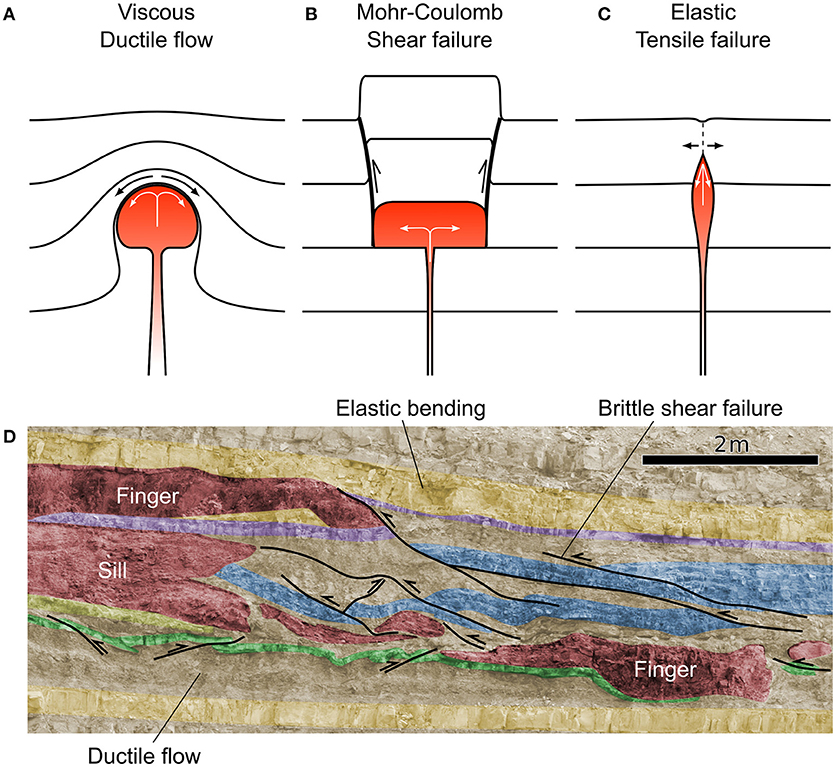
Figure 1. Diagram of idealized end-member cases of magma ascent. (A) A diapir (viscous end-member) indents and displaces the surrounding host rock extensively, making the host rock viscosity a fundamental parameter for governing ascent rate. (B) A punched laccolith (brittle shear failure end-member) indents and displaces the overburden, which fails along plastic, brittle faults. (C) A dyke (elastic end-member) fractures and intrudes the host rock with negligible host rock displacement, thus, the ascent rate is primarily controlled by host rock fracture strength and magma viscosity. Adapted from Rubin (1993). (D) Interpreted field photograph of outcrop exposing a sheet-like sill, magmatic fingers, and the associated structures in the shale-carbonate host rock, Cuesta del Chihuido, Mendoza Province, Argentina (Spacapan et al., 2017). The outcrop shows that the sill tip is round or blunt, and that both ductile deformation of the shale layers, brittle shear faulting of thin carbonate layers and elastic bending of thick carbonate layers accommodate the emplacement and propagation of the sill. Detailed descriptions of the structures and associated mechanisms can be found in Spacapan et al. (2017).
However, the Earth's crust is neither purely viscous, plastic, nor elastic, but, as stated, visco-elasto-plastic. Therefore, even if purely viscous diapiric rise, plastic faulting, or elastic hydraulic fracturing may happen, most intrusions are likely to be accommodated by hybrid viscous, plastic, and elastic deformations of the host (Rubin, 1993; Vachon and Hieronymus, 2016; Scheibert et al., 2017).
This statement is corroborated by field observations of igneous sills emplaced in shale-carbonate rocks, which exhibit complex brittle-ductile deformation that accommodated the emplacement of the magma (Schofield et al., 2012; Duffield et al., 2016; Spacapan et al., 2017) (Figure 1D). Moreover, field observations in the host rock of thin laccoliths in the Henry Mountains, Utah, evidence significant plastic shear failure and ductile deformation of the overburden (Román-Berdiel et al., 1995; de Saint Blanquat et al., 2006; Wilson et al., 2016), in contrast to the elastic assumptions of the theoretical models (e.g., Pollard, 1973; Bunger and Cruden, 2011).
Seismicity monitored in active volcanoes also highlights the complex mechanical behavior of the crust during dyke emplacement. While dyke emplacement models assume tensile propagation in purely elastic host rock, earthquake swarms monitored during dyke propagation exhibit numerous, if not most dominant, double-couple focal mechanisms interpreted as shear faulting (e.g., Borandsdottir and Einarsson, 1979; Ukawa and Tsukahara, 1996; Battaglia et al., 2005; Roman and Cashman, 2006; White et al., 2011; Ágústsdóttir et al., 2016). These geophysical observations suggest that shear failure can significantly accommodate dyke propagation, and that the plastic Coulomb properties of the crust are likely at work during dyke propagation, in contrast to the established theories.
Finally, the sheet morphologies of sills and saucer-shaped sills were used to argue that they result from tensile hydraulic fracturing (e.g., Bunger and Cruden, 2011; Galland and Scheibert, 2013; Kavanagh et al., 2015), similar to dykes. Recent models, however, show that the emplacement of saucer-shaped sills is likely controlled by the shear failure of their brittle overburden (Haug et al., 2017, 2018). These models show that the Coulomb plastic properties of the crust likely play an important role in the emplacement of sheet intrusions, again in contradiction to the tensile elastic assumptions of established models of sheet intrusion emplacement.
These observations highlight that the end-member rheological assumptions of the current theoretical, laboratory, and numerical models of magma emplacement have limited physical validity because the host-magma interaction is too simplified. In addition, because the models assume rheological end-members, they cannot simulate the natural diversity of magma intrusion shapes and magma emplacement mechanisms, and so they are of limited use to predict under which conditions intrusions of contrasting shapes form. Such limitation lead to the heated debates in the 80-90's that opposed the diapiric vs. hydraulic fracturing models for granite emplacement, whereas field evidences supported both mechanisms (e.g., Rubin, 1993; Petford, 1996; Miller and Paterson, 1999; Petford and Clemens, 2000). These limitations lead to the following questions, as highlighted by Rubin (1993):
1. How does combined viscous, plastic, and elastic (subsequently referred to as “hybrid”) deformation of the host control the emplacement of magma?
2. What properties govern the transition between brittle and ductile intrusion mechanisms, and under which conditions might hybrid behaviors occur?
3. What are the characteristic patterns of hybrid deformation during magma emplacement, and how do we identify the end-member intrusion mechanisms?
Answering these questions requires the design of a model able to simulate the injection of a viscous fluid into a matrix of controllable and variable rheological properties. Several laboratory studies in the physics community implemented such an approach to constrain the dynamics of viscous fingering vs. viscoelastic fracturing (e.g., Lemaire et al., 1991; Hirata, 1998; Nase et al., 2008; Sumita and Ota, 2011). However, these models focused on the morphology of the intruding fluid only, such that the complex deformation happening within the host matrix was not observed, and so not understood. In this paper, we present exploratory laboratory models designed to constrain the deformation mechanisms accommodating viscous fluid injection into a viscoelastic host. To achieve this, we used a polariscope to monitor birefringence patterns corresponding to deformation of the viscoelastic host matrix. Our exploratory experiments highlight contrasting ductile and brittle deformation patterns accommodating the emplacement of, among others, viscous fingers, hydraulic fractures and hybrid intrusions.
In our model, the host rock is represented by a colloidal aqueous gel of laponite RD, a synthetic smectite clay produced by BYK Altana. The laponite gel can display a wide range of viscoelastic behaviors for different concentration, salt content, pH, and curing time (Ruzicka and Zaccarelli, 2011a; Ruzicka et al., 2011b). A major rheological trait of laponite gel is that it shows shear-thinning and thixotropy (e.g., Pignon et al., 1997; Bonn et al., 2002). The magma is represented by dyed olive oil with a Newton viscosity measured at μ = 99±0.1 mPa s using a VEB MLW falling ball viscosimeter (Bertelsen, 2014).
Our experiments are prepared by filling a rectangular Hele-Shaw cell of width × height = 520 × 570 mm, gap = 5 mm) with an aqueous laponite mixture (Figure 2). The depth of the injection inlet is ca. 30 cm. After controlled curing at room temperature, the mixture becomes a viscoelastic gel. When the gel is ready, a syringe pump injects the viscous magma analog into the viscoelastic gel at constant flow rate. We followed the rigorous laponite gel preparation protocol described by Ruzicka and Zaccarelli (2011a) and Ruzicka et al. (2011b), which is necessary to ensure reproducible mechanical properties of the laponite gel (see detailed procedure description by Bertelsen, 2014).
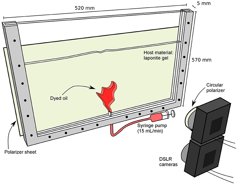
Figure 2. Drawing of the experimental setup. A Hele-Shaw cell filled with a viscoelastic laponite gel is intruded by dyed olive oil. The cell is backlit with a diffused white light source. Intrusion flow rate is controlled with a syringe pump. The cell stands between a polarizer sheet and a circular polarizer mounted on the camera lense: strain-induced birefringence in the gel, as well as the gel/oil interface, is captured by the camera because the polarizers are crossed.
With the laponite concentration used in this study, the laponite gel is optically isotropic when not strained or when only viscous deformation accommodates strain. When the gel exhibits elastic strain, it becomes birefringent (e.g., Mourchid et al., 1998). To image the strain patterns associated with the propagating oil intrusion, the cell is placed in a polariscope composed of a polarizer sheet placed behind the cell and a DSLR camera holding a circular polarizer (Figure 2). During the experiments, our setup allows monitoring simultaneously both the evolution of the shape of the intruding fluid and a birefringence map within the viscoelastic gel (Figure 3). Another DSLR camera also monitors the experiments with natural light, i.e., without a circular polarizer. The cameras shot pictures with frequency of 1 Hz.
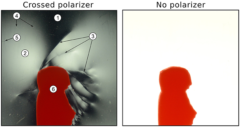
Figure 3. Left: Characteristic polarized photograph displaying birefringence patterns in the laponite gel. (1) Dark, unstrained gel. (2) Diffused birefringence lobe. (3) Hairline birefringence jumps. (4) White patches of laponite particle clusters. (5) Crossed patterns of birefringence around a rigid impurity in the gel. (6) Red oil. Right: photograph (same area/time) without polarizer. Note the lack of features shown in the gel in the unpolarized photograph as compared to the polarized photograph.
In this paper we present a series of seven exploratory experiments for testing the influence of the visco-elasto-plastic host rheology on the fluid emplacement (Table 1). The laponite concentration was constant (laponite to water mass fraction: wi = 3.3±0.1 wt. %), while the curing time was varied from 0 min to 240 min. Short curing time corresponds to weak, dominantly viscous gel, whereas long curing time corresponds to stiff, dominantly elastic gel (Kaushal and Joshi, 2014). In all experiments, olive oil was injected at the same flow rate (15 mL min−1).
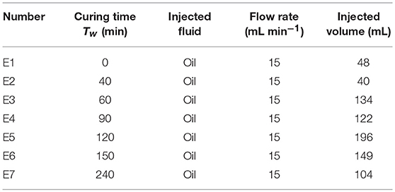
Table 1. List of experiments and experimental parameters.
It is important to constrain the rheological properties of the laponite gel matrix. We qualitatively estimated the mechanical behaviors of the laponite used in this study from the data of Kaushal and Joshi (2014), who measured the creep compliance and stress relaxation moduli for laponite gels at different curing times. The creep compliance expresses the ability of a material to creep; high values of creep compliance implies that the material flows easily, therefore the material behaves more as a viscous fluid than an elastic solid. The stress relaxation modulus, on the other hand, expresses how much a material releases stress due to non-reversible flow; high stress relaxation modulus implies limited stress relaxation ability, therefore the material behaves more elastic and hardly flows. Kaushal and Joshi (2014) showed a decrease of creep compliance and an increase of stress relaxation moduli with increasing curing time. This means that short curing times lead to low viscosity and dominantly inelastic gels, whereas long curing times lead to higher viscosity and more elastic gels. Note that the laponite concentration in the study of Kaushal and Joshi (2014) (3.5%) is slightly higher than in our experiments (3.3%). However, we expect that the trends measured in the gels of Kaushal and Joshi (2014) are similar to those of our gels, albeit with shorter curing times and stiffer gels (see also Ruzicka and Zaccarelli, 2011a; Ruzicka et al., 2011b), as subsequently confirmed by our results.
Before describing the evolution of the seven experiments presented in this paper, we will describe the main characteristics of the observed birefringence patterns (Figure 3). We observe two main types of birefringence features: distributed birefringence zones with gradual lateral variations (2 in Figure 3) and hairline abrupt birefringence jumps within the matrix (3 in Figure 3). These hairline features are concentrated around the irregular inflating parts of the intrusion; they are visible from the start and are maintained until the end of the experiments once they are formed. In the polarized images, one also observes small white spots (4 in Figure 3), interpreted as clusters of laponite particles, as well as dark blur crosses (5 in Figure 3), interpreted as strain shadows around more rigid heterogeneities. Large dark areas also indicate no birefringence of the gel (1 in Figure 3).
In all experiments, the oil propagate upward toward the surface. The oil injection systematically triggers uplift of the gel surface, forming a dome, with the exception of experiment E1 (Figure 4).
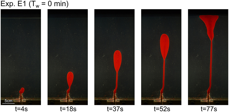
Figure 4. Time series of polarized light photographs of Experiment E1 (Tw = 0 min).
In experiment E1 (Tw = 0 min, low gel strength), the oil intrusion initiates as a rounded blobby body (Figure 4, left). It subsequently develops an inverted tear drop shape, with an upward migrating upper head connected to the injection inlet by a thin channel. The leading head is systematically wider than the lower thin channel. The shape of the intrusion is rounded and smooth, until it reaches the surface of the gel (Figure 4, left). Note that we do not observe any birefringence in the gel.
In experiment E2 (Tw = 40 min), the oil intrusion starts as a rounded blob (Figure 5, left), similarly to experiment E1. Subsequently, the oil intrusion develops a subvertical conduit that propagates upward. The tip of the conduit is relatively rounded, but the degree of curvature is higher than that of the intrusion in experiment E1 (Figure 4). Polarized photographs display a weak distributed birefringence pattern, which is significantly more prominent close to the propagating tip of the intrusion. The birefringence is symmetrical on both sides of the intrusion. At t = 40s, weak and distributed birefringence lobes seem to connect the intrusion tip to the edges of the uplifted dome at the surface. This birefringence lobe also spreads downward, parallel to the sub-vertical walls of the intrusion.
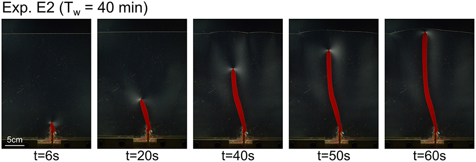
Figure 5. Time series of polarized light photographs of Experiment E2 (Tw = 40 min).
In contrast to experiments E1 and E2, the shapes of the oil intrusions in experiments E3 (Tw = 60 min) to E5 (Tw = 120 min) are irregular, with alternating wide and thinner domains (Figures 6–8). One can observe some straight segments of the intrusion walls, separated by relatively sharp angles. The birefringence intensities are higher than in experiments E1 and E2 and concentrate near the main thickening irregularities of the oil intrusions. We also systematically observe hairline birefringence jumps nucleating at the acute angle irregularities of the oil intrusions. These hairline birefringence jumps are more numerous and longer from experiment E3 to experiment E5 (Figures 6–8). These structures appear sharper in experiment E5 than in experiments E3 and E4.
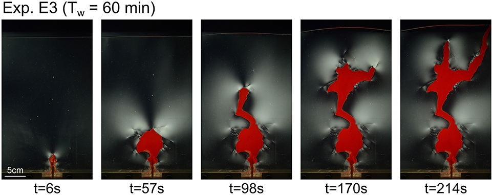
Figure 6. Time series of polarized light photographs of Experiment E3 (Tw = 60 min).
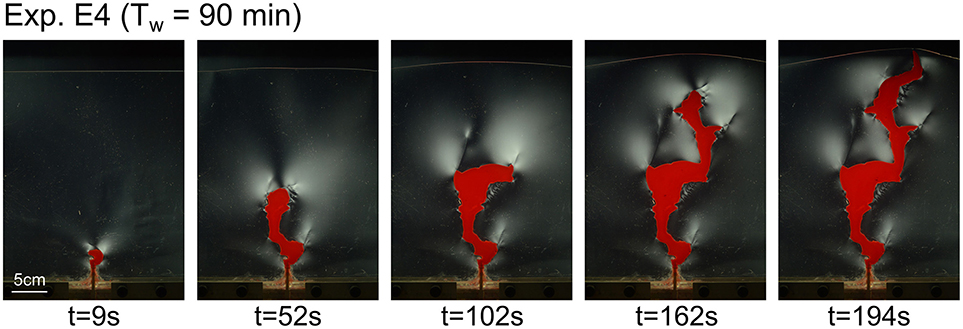
Figure 7. Time series of polarized light photographs of Experiment E4 (Tw = 90 min).
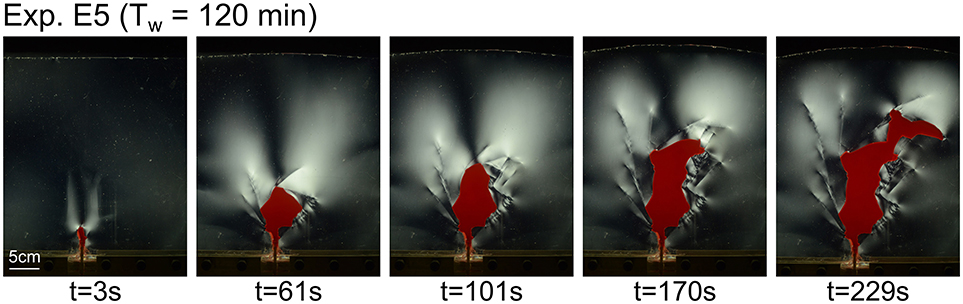
Figure 8. Time series of polarized light photographs of Experiment E5 (Tw = 120 min).
The intrusion in experiment E6 develops in two stages. The first stage extends until t≈50s, where the intrusion grows as a thin irregular conduit (Figure 9). During this stage, birefringence patterns exhibit continuous lobes, without hairline birefringent jumps. From t≈50s, the upper tip of the intrusion thickens while propagating. During this thickening stage, prominent hairline birefringent jumps nucleate from the angular irregularities of the intrusion walls (Figure 9).
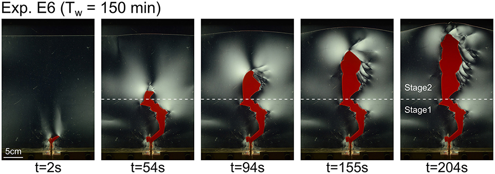
Figure 9. Time series of polarized light photographs of Experiment E6 (Tw = 150 min).
The evolution of the intrusion in experiment E7 develops in three main stages. During the first stage until t≈30 s, the intrusion grows as a regular, thin oblique conduit (Figure 10). During this stage, the main birefringence exhibits small continuous lobes concentrated at the sharp tip of the intrusion. During the second stage, the tip of the intrusion thickens and develops an irregular, blobby shape. During this second phase, wide birefringence lobes exhibit sharp jumps (Figure 10). At t≈90 s, the third stage starts with the initiation of a thin oil conduit that follows a hairline birefringence jump formed during the second stage (Figure 12E). From then, the intrusion grows as thin, regular conduits with very sharp tips. Intense, continuous birefringence lobes concentrate at the propagating sharp tips of the intrusion (Figure 10).
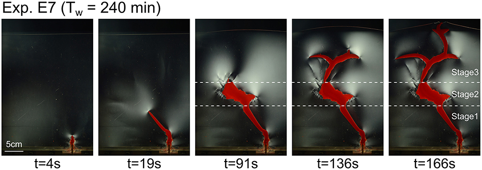
Figure 10. Time series of polarized light photographs of Experiment E7 (Tw = 240 min).
Figure 11A displays the time evolutions of the intrusions' contours during all experiments. The time gap between the grey contours is 4 s, while the time gap between the black contours is 20 s. The distance between the contours provides a graphic indication of the evolution of the displacement velocity of the intrusions' walls in all directions: the closer the contours are, the slower the intrusions' walls move. The comparison between the contours evolutions of experiments E2 and E7 is essential to highlight subtle, but essential, differences. In experiment E2, the subvertical walls of the conduit are almost perfectly parallel, defining a finger-shape. The thickness of the intrusion is set almost from the beginning of the experiment; subsequently, only the tip propagates upward, while the thickness of the underlying conduit remains constant during the whole experiment (Figure 11A, E2, t≈40 s). Conversely, during experiment E7, the shape of the thin conduit emplaced during the first stage is that of a thin wedge pointing toward the intrusion tip (Figure 11A, E7, t≈240 s). In addition, the fourth to sixth contours of Figure 11A (E7, t≈240 s) show that the growth of the conduit during this first stage occurs by both tip propagation and thickening of the thin wedge-shape conduit.
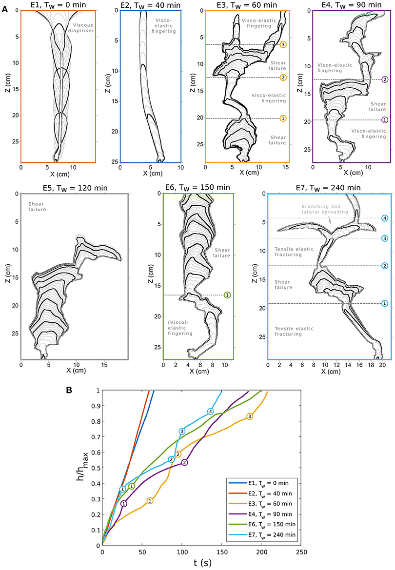
Figure 11. (A) Maps of time evolutions of intrusions' contours calculated with image analysis. The time gap between the gray contours is 4 s, while the time gap between the black contours is 20 s. Numbers indicate the position of the intrusion tips when morphological transitions occur during intrusion evolution. The labeling of the emplacement modes for the identified stages refers to interpretation in section 4.2 and in Figure 12. (B) Plot of scaled position of the uppermost tip of the intrusions (h/hmax) as a function of time for all experiments but E5. The numbers correspond to the morphological transitions identified on intrusion shape maps in (A). Note that these morphological transitions coincide with sharp kinks of propagation velocity.
Figure 11B displays the evolution of the dimensionless position h/hmax of the uppermost tip of the intrusions; here hmax corresponds to the distance between the tip of the inlet and the initial gel surface. Figures 11A,B evidences a time correlation between the morphological evolutions of the intrusions and their propagation velocity. In experiments E1 and E2, i.e., those with shorter curing times, intrusions keep their shapes during the entire experiments, while their propagation velocity remains constant. In experiment E2, the contour map shows that the thickness of the conduit remains constant during the whole experiment (Figure 11, E2, t ≈ 40 s). The evolution of intrusion in Experiment E3 is more complex, and we identify three morphological transitions. Transition 1 (Figure 11, E3, t≈60 s) corresponds to a sudden shift from a massive blob to a narrower conduit, and corresponds to an acceleration of the intrusion tip. Transition 2 (Figure 11, E3, t≈90 s) is the opposite, such that it marks a sudden widening of the intrusion head along with a deceleration of the intrusion tip. Finally, transition 3 (Figure 11, E3, t≈180 s) marks again a sudden narrowing of the intrusion and an acceleration of the intrusion tip. Similar correlation is visible in Experiment E4, during which transition 1 (Figure 11, E4, t≈25 s) marks a sudden widening of the intrusion head along with a deceleration of the intrusion tip. In addition, transition 2 (Figure 11, E4, t≈100 s) marks the sharp transition from a wide intrusion head to the initiation of a thin conduit, along with a sharp acceleration of the intrusion tip. In Experiment E6, we identify one transition only (Figure 11, E6, t ≈ 40 s), but it is not as sharp as those identified in Experiments E3 and E4. Finally, we identify four clear and sharp transitions during experiment E7 (Figure 10). Transition 1 (Figure 11, E7, t≈25 s) marks the sudden widening of the intrusion head along with a sudden deceleration of the intrusion tip; Transition 2 (Figure 11, E7, t≈90 s) marks the initiation of a thin sub-vertical conduit along with the sudden acceleration of the intrusion tip; Transition 3 (Figure 11, E3, t≈100 s) marks the sudden splitting and lateral spreading of the intrusion along with a sudden deceleration of the intrusion tip; finally transition 4 (Figure 11, E3, t≈140 s) marks the sudden initiation of a new sub-vertical thin conduit along with a sharp acceleration of the intrusion tip. Note that the initial propagation velocities in Experiments E1, E2, E6, and E7 are almost equal, even if the initial conditions strongly differ. In addition, the shapes of the early oil conduits in Experiments E2 and E7 are very similar, i.e., thin conduits with tips of low angles of curvature.
The birefringence patterns observed in the laponite gel in the experiments qualitatively highlight where deformation in the gel occurs. In this section, we will interpret which deformation mechanisms can be inferred from such birefringence patterns. In experiment E1 (Tw = 0 min), we observe no birefringence in the gel, while it deforms to accommodate the flow of the oil (Figure 4). In this experiment, the curing time Tw is so short that the laponite mixture does not have the time to build a gel structure in the solution, so we infer that it dominantly flows viscously. In experiments E2 to E7, i.e., with increasing curing times, it appears that the amount of birefringence increases (Figures 5–10). Correlating this observation with the results of Kaushal and Joshi (2014), which show that increasing curing time Tw leads to more elastic laponite gel, we infer that the birefringence observed in our experiments is a proxy for elastic deformation of the gel. In experiment E2 (Tw = 40 min), the birefringence is weak (Figure 5), suggesting that a small fraction of the gel deformation is elastic, while the rest is viscous.
In experiments E2 to E7, one can observe both birefringence within the gel and uplift of the surface of the gel (Figures 5–10). The uplift of the laponite gel occurs as a domed surface, at the apex of which outer-arc elastic stretching is expected (e.g., Pollard and Johnson, 1973; Galland and Scheibert, 2013; Galland et al., 2016). However, no birefringence is observed where significant elastic stretching is expected (Figures 7–10). We infer from this observation that birefringence in the laponite gel is a proxy for elastic shear strain, not normal strain.
The hairline birefringence jumps (Figure 3) are only observed in experiments E3 to E7 (Figures 6–10), i.e., those with the longest curing time Tw. We interpret such birefringence discontinuities as fractures within the gel. Given that these fractures do not appear to accommodate space opening, we interpret these fractures to result from shear failure, i.e., faulting. This deformation mechanism is neither elastic nor viscous, but brittle. In the following sections, we will refer to this brittle behavior as plastic, as opposed to elastic and viscous.
To summarize, we infer that the laponite gels in our experiments deform by either viscous flow, elastic strain or plastic shear failure, or a combination of them, according to the curing time of the gel.
The understanding of the gel deformation mechanisms combined with the oil intrusion shapes reveals diverse oil emplacement mechanisms in our experiments.
In experiment E1 (Tw = 0 min; Figure 4), the lack of birefringence strongly suggests that the gel flows in a viscous manner. In addition, the shape of the oil intrusion, with a propagating head that is wider than the lower tail, strongly suggests that part of the oil emplacement is driven by buoyancy, similar to a Rayleigh-Taylor instability (Figure 12A). In addition, the forceful injection of the oil phenomenologically corresponds to the injection of a fluid within a fluid of different viscosity, similarly to a Saffman-Taylor instability (Saffman and Taylor, 1958; Saffman, 1986), or viscous fingering (Lemaire et al., 1991; Hirata, 1998). Because our experimental cells are vertical, gravity and resulting buoyancy forces contribute to oil propagation, in contrast to the experiments of Saffman and Taylor (1958), Lemaire et al. (1991), and Hirata (1998), where the cells were horizontal. Nevertheless, we cannot rule out that surface tension between the aqueous gel and the intruding oil is significant enough to control the formation of the inverted drop shape of the intrusion, similarly to a Rayleigh-Plateau instability (e.g., de Gennes et al., 2004).
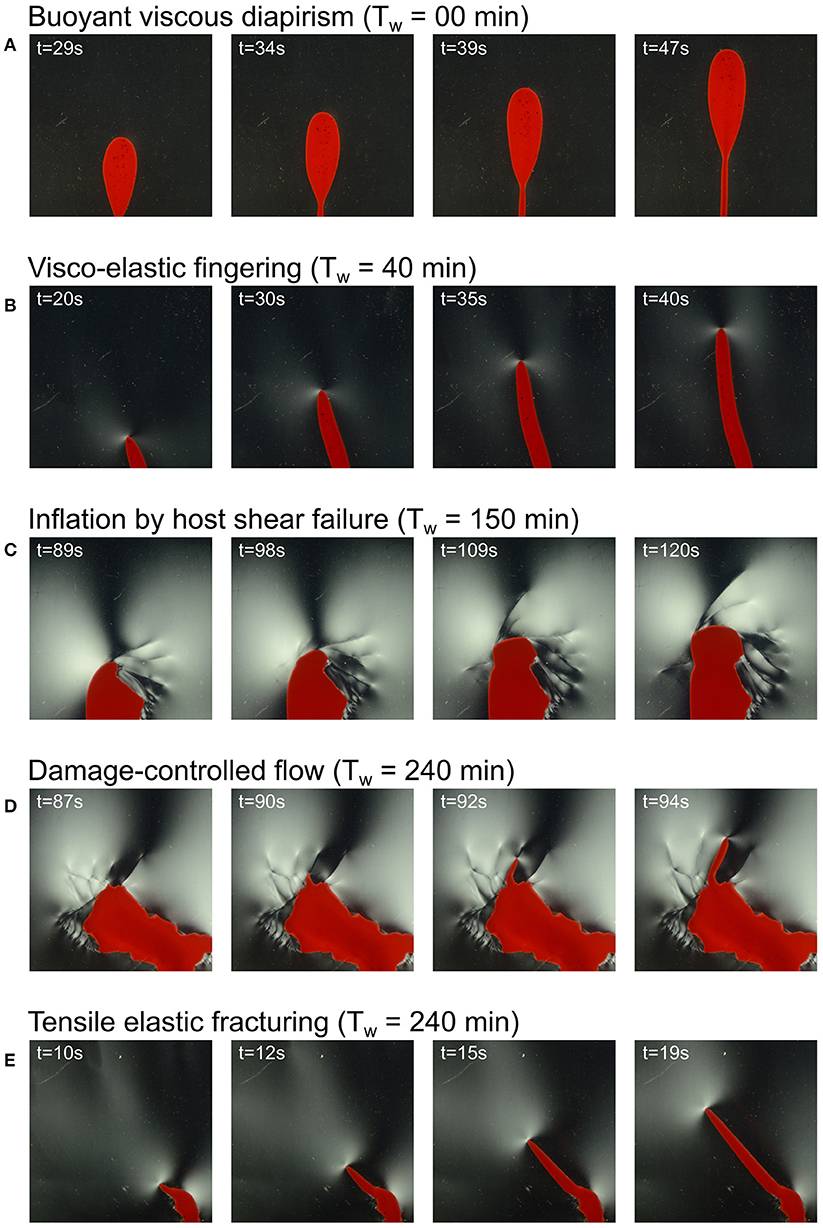
Figure 12. Time series of polarized photographs illustrating characteristic mechanisms of oil emplacement. (A) Viscous diapirism in Experiment E1 (Tw = 0 min). (B) Viscoelastic fingering in Experiment E2 (Tw = 40 min). (C) Intrusion inflation by shear failure of the host in Experiment E6 (Tw = 150 min). (D) Intrusion of sheet intrusion along damage/fault produced during earlier steps of oil intrusions in Experiment E7 (Tw = 240 min). (E) Hydraulic fracturing of sheet intrusion in Experiment E7 (Tw = 240 min).
In experiments E3 to E7 (Figures 6–10), the development of hairline birefringence jumps accompanied the growth of irregular and relatively thick inflating parts of oil intrusion. We infer from section 4.1 that the oil emplacement occurs by plastic shear failure of the gel (Figure 12C). In this mechanism, the oil pushes the gel, the displacement of which is accommodated along shear fractures, i.e., faults. This mechanism accommodates the emplacement of relatively wide intrusions. In addition, the development of several shear fractures control the angular irregularities of the intrusion walls. This mechanism is very similar to the fault-assisted emplacement of punched-laccoliths (e.g., Corry, 1988; Schmiedel et al., 2017).
In most experiments exhibiting hairline birefringence jumps, the oil does not flow along the shear fractures induced by its propagation. In experiment E7, however, one can see that the initiation of the third underwater stage of emplacement corresponds to the initiation of a thin sheet, which follows a shear fracture that accommodated the earlier growth and thickening of the intrusion during the second stage of emplacement (Figure 12D). This mechanism of damage-controlled flow is in good agreement with the laboratory models of Abdelmalak et al. (2012) and Schmiedel et al. (2017), and the numerical models of Haug et al. (2017) and Haug et al. (2018).
Finally, in experiment E7, the oil intrusion during the stages 1 and 3 described in section 3 exhibits a regular sheet-like shape with a sharp tip (Figures 10, 12E). In addition, the birefringence pattern exhibits localized concentration at the tip (Figure 12E). In this experiment, the gel is expected to be stiffer than in all the other experiments. We infer from these observations that the oil propagates by a mechanism that is close to elastic tensile fracturing. This mechanism is one of the most established to account for the emplacement of sheet intrusions, such as dykes and sills (e.g., Pollard and Johnson, 1973; Rubin, 1993; Rivalta et al., 2015; Galland et al., 2018).
The intrusions in experiment E2 and in the first stage of experiment E7 look rather similar, such that their morphologies are not sufficient to discriminate between their emplacement mechanisms. However, several subtle differences allow us to interpret distinct emplacement mechanisms. First, the birefringence signal in experiment E2 (Figure 5) is much weaker than that in experiment E7 (Figure 10). This suggests that substantial elastic deformation of the gel is at work in experiment E7, whereas a significant part of the gel deformation in experiment E2 is accommodated by inelastic flow (see also interpretation in section 4.1). Second, the shapes and growth behaviors of the intrusions in both experiments differ. In experiment E7, the intrusion during the first stage exhibits a thin wedge, which thickens while its tip propagates (Figure 11A, Tw = 240 min). Such behavior is in good agreement with the propagation of a fluid-filled fracture, the thickness of which is expected to be proportional to the length (e.g., Pollard, 1973, 1987; Rubin, 1993; Galland and Scheibert, 2013). We thus infer that the thin intrusion of the first stage of experiment E7 is likely a tensile fracture in a dominantly elastic host matrix. Conversely, in experiment E2, the oil intrusion exhibits a finger shape with parallel walls [Figure 11A (Tw = 40 min) and Figure 12B]. In addition, the growth of the intrusion occurs only through tip propagation, but without thickening of the early parts of the intrusion (Figure 11A; Tw = 40 min). This growth behavior is incompatible with a mechanism of fracture propagation through an elastic medium. In contrast, such behavior is very similar to a Saffman-Taylor instability (Saffman and Taylor, 1958; Saffman, 1986), i.e., the viscous fingering of a low viscosity fluid into a fluid of higher viscosity. In addition, such viscous fingering has also been observed in a non-Newtonian, including sheart-thinning, viscoelastic host matrix (Nase et al., 2008). Given that the laponite gel is shear-thinning, and the weak birefringent pattern in experiment E2 showing some component of elastic strain, it is likely that such complex visco-elastic fingering controls the emplacement of the oil in this experiment. Nevertheless, a firm interpretation would require more data.
The plot of Figure 11B shows that the propagation velocities of the intrusion tips exhibit significant differences with respect to different curing times Tw. The constant propagation velocities in experiments E1 and E2, i.e., those with shorter curing times, are compatible with a deformation that is distributed within the gel matrix. This is in good agreement with a dominantly viscous deformation of the laponite gel. In contrast, the variable propagation velocities of the intrusions' tips suggest that another mechanism accommodates the emplacement of the oil. The abrupt velocity changes visible during experiments E3 to E7 (Figure 11B) are compatible with discrete deformational events. This is in good agreement with fracturing of the gel matrix, which is corroborated by the occurrence of the shear fractures in the gel (Figures 6–10). Note that the data plotted on Figure 11B correspond to one point only of the growing intrusions, i.e., the uppermost tip. The contour maps displayed in Figure 11A shows that the propagation velocity of the intrusions is variable at all points and in all directions. A quantitative analysis of the complex propagation of the intrusions' walls might provide valuable insights on the emplacement dynamics of the oil with respect to the visco-elasto-plastic behavior of the gel matrix.
To summarize, our experiments show how the shapes of the oil intrusions are controlled by the deformation mechanism of the gel matrix: the rounded shape in experiment E1 dominantly results from viscous flow of the gel, the regular finger in experiment E2 dominantly results from viscoelastic fracturing of the gel, the angular and irregular shapes in experiments E3 to E7 dominantly result from shear faulting of the gel, and the sharp-tipped thin sheet in experiment E7 dominantly results from elastic tensile fracturing. Our experiments are thus able to model – for the first time – most mechanisms of magma emplacement inferred from geological observations.
A strong assumption of our experimental apparatus is that it has 2-dimensional geometry, whereas igneous intrusions in nature are 3-dimensional structures. Such geometry implies potential severe boundary effects on the results. However, the laponite gel is shear thinning, i.e., it weakens when strained, such that it self-lubricates against the acrylic glass walls of the cell, and so reduces the boundary effects. The boundary conditions of our model system are therefore close to plane strain. For more details, Bertelsen (2014) discusses in detail the limitations of the 2D Hele-Shaw cell on the results. In our apparatus we chose a gap of 5 mm between the acrylic glass plates. This ensures that the gel layer is thick enough to produce visible and interpretable birefringence patterns through the polariscope; if the gap were smaller, the gel layer would be too thin, given that the amount of birefringence through a gel layer is proportional to the thickness of the layer (e.g., Fuller, 1995).
The birefringence patterns visible on Figures 4–12 provide invaluable insights about the deformation mechanisms of the gel. Such information is absolutely not reachable on photographs taken with natural light; actually, close direct observations of the gel during experiments show that it looks perfectly homogeneous in natural light, and even the fractures highlighted by the hairline birefringence jumps are invisible. Without polariscope, Lemaire et al. (1991) and Hirata (1998) based their physical analyses of the fluid injection in viscoelastic gels on the shapes of the intruding fluid. Our study shows that the mechanical information provided by the use of a polariscope is invaluable for revealing the complex deformation regimes in the deforming visco-elasto-plastic gel. It shows that the use of a polariscope is essential for revealing the deformation mechanisms in experiments using birefringent gels, such as laponite and gelatine.
The observed birefringent signals is integrated over the full thickness of the models. In our 2-dimensional cell, given that the structures are dominantly perpendicular to the walls, the polarized light crosses the gel perpendicular to the structures in the gel, so that each structure is well visible on the observed birefringence patterns. In addition, the use of a high-resolution DSLR camera allows imaging fractures in the gel evidenced by the sharp hairline birefringence jumps (Figure 3). In 3-dimensional gel models, resolving each fracture with polariscopy would be impossible because (1) structures can be out-of-plane with respect to the light source and (2) the light can cross several structures (e.g., Taisne and Tait, 2009). Another method used to image deformation in 3-dimensional gel experiments implements the tracking of particles in suspension in the gel and illuminated by a laser sheet (e.g., Kavanagh et al., 2015, 2018). Nevertheless, the resolution of the digital image correlation for particle tracking is not enough to image sharp structures like the fractures we observe.
Our experiments simulate several mechanisms of emplacement of a viscous fluid into a visco-elasto-plastic matrix: (1) emplacement by viscous flow, (2) emplacement by shear brittle failure, i.e., faulting, and (3) emplacement by tensile failure, i.e., hydraulic fracturing. These three emplacement mechanisms have been inferred to govern magma emplacement at diverse levels of the Earth's crust (e.g., Corry, 1988; Rubin, 1993; de Saint Blanquat et al., 2006). Our experiments are the first able to account, in the same model system, for most of the main magma emplacement mechanisms documented in nature. Our models are thus of great potential for revealing the complex physics governing magma emplacement in the visco-elasto-plastic crust. In addition, they offer a unique tool to constrain the physical conditions that are favourable for each dominant emplacement mechanism.
In all our experiments, the gel exhibits both viscous, plastic and elastic properties, but depending on Tw, one property is dominant with respect to the others. For example, in experiment E1 viscous flow of the gel is dominant, whereas elastic deformation is likely dominant in experiment E7. In the other experiments, however, it is likely that several mechanisms of gel deformation are at work at the same time. For example, the emplacement of the intrusion in experiment E3 (Figure 6) likely results from a complex combination of viscous flow, elastic strain and shear fracturing of the gel matrix, i.e., hybrid emplacement mechanism. In these experiments, the complex shapes of the intrusions reflect the complex magma intrusion shapes observed in nature (e.g., Bartley et al., 2012; Burchardt et al., 2012; Spacapan et al., 2016). This suggests that such hybrid emplacement mechanisms, i.e., involving coeval viscous, plastic (brittle) and /or elastic deformation of the host rock, is likely at work during the emplacement of magma intrusions in nature (Pollard, 1973; Spacapan et al., 2017). This shows that magma emplacement models based on end-member host rock rheology (viscous, plastic, or elastic) are too simplistic to address the complex emplacement of magma in the Earth's crust, as already demonstrated by Rubin (1993), Vachon and Hieronymus (2016), and Scheibert et al. (2017). Our models, on the other hand, have the potential to address such complexity.
The structures in our experiments are in good agreement with geological and geophysical observations. For example, the shear fractures visible in our experiments can be related to the numerous structures accommodating the emplacement of intrusions of diverse sizes and shapes, such as large laccoliths (de Saint Blanquat et al., 2006; Wilson et al., 2016) and igneous sills (Pollard, 1973; Pollard and Johnson, 1973; Spacapan et al., 2017) (Figure 1). In addition, seismological measurements evidence dominant shear failure associated dyke emplacement (White et al., 2011; Ágústsdóttir et al., 2016) and cryptodome emplacement (e.g., Okada et al., 1981; Merle and Donnadieu, 2000), suggesting again more complex propagation mechanisms than tensile failure are at work in geological systems. Finally, the shear fractures in our experiments E3 to E7 are in good agreement with laboratory models of magma emplacement in dry granular materials (Merle and Donnadieu, 2000; Guldstrand et al., 2007; Mathieu et al., 2008; Abdelmalak et al., 2012; Schmiedel et al., 2017), in which the magma propagates by pushing its host until shear failure, i.e., the so-called viscous indenter model.
The oil intrusions in experiment E2 (Figure 5) and during the first stage of experiment E7 (Figure 10) exhibit very similar shapes. However, we discussed in section 4.2 that the intrusion in experiment E2 is likely emplaced by viscoelastic fingering with dominant viscous flow of the gel, whereas the intrusion in experiment E7 is likely emplaced by tensile fracturing, with dominant elastic deformation of the gel. We conclude that the morphology of an intrusion alone is not a sufficient proxy for inferring its emplacement mechanism. This implies that intrusions exhibiting sheet morphology do not systematically result from tensile fracturing, as they can also result from viscoelastic fingering. This conclusion is unambiguously supported by the detailed field study of Spacapan et al. (2017), who demonstrate that the propagation of a sheet-shaped sill was accommodated by significant ductile, compressional deformation of the host rock, in agreement with the viscoelastic fingering mechanism. Such a result is in disagreement with most of the literature, which assumes that the sheet shapes of, e.g., dykes and sills are systematic proxies of tensile fracturing of a dominantly elastic host (e.g., Pollard, 1987; Rubin, 1995; Rivalta et al., 2015, and references therein). This result can also have significant implications for geodetic modeling, given that most geodetic models used to invert geodetic data associated with the emplacement of dykes or sills are based on the assumption that these intrusions formed by tensile opening within a purely elastic host rock (e.g., Sigmundsson et al., 2010; Wright et al., 2012), even when field observations contradict these assumptions. To summarize, even if sheet intrusions resemble simple tensile fractures, their emplacement can be governed by other, more complex processes. We conclude that, in order to reveal the emplacement mechanisms of sheet intrusions, among others, it is essential to investigate both (1) the intrusion shapes and (2) the deformational structures in the host accommodating magma emplacement (see e.g., Spacapan et al., 2017).
The intrusions modeled in experiments E3 to E7, as well as the deformational structures in the gel, exhibit very complex and discrete structures, which are typical of brittle behavior. Interestingly, the initial conditions of our experiments are simple, with gels that are prepared to be as homogeneous as possible. The occurrence of the observed complex, discrete structures in our experiments show that complex brittle structures occur spontaneously from a macroscopically homogeneous solid. Such behavior suggests that the gel exhibits numerous, very small-scale heterogeneities that control the stochastic properties of brittle fracturing, similarly to flaws in natural rocks. Stochastic fracturing processes have, for example, been inferred to control the nucleation and the thickness of dykes (Krumbholz et al., 2014). In addition, the variable intrusion propagation velocities observed in experiments E3 to E7, i.e., in experiments with brittle shear deformation, show that the propagation occurs through successive stages of fast propagation and accumulation, each stage corresponding to distinct emplacement mechanisms associated with distinct mechanical behavior of the host rock. Such stepwise behavior has been observed e.g., during propagation of dykes (White et al., 2011; Ágústsdóttir et al., 2016), suggesting that sudden dyke acceleration and deceleration are associated with distinct deformation modes of the crust. The behavior of the laponite gel therefore seems to reproduce the stochastic properties of the brittle crust.
We discussed in the former sections that the laponite gel in our experiments exhibits complex visco-elasto-plastic behaviors, which reproduce phenomenologically the mechanical behaviors of the Earth crust. A challenge, however, is to discuss the physical similarity between the mechanical behaviors of the laponite gel and those of natural rocks (Barenblatt, 2003). This requires systematic measurements of the mechanical properties (e.g., elastic modulus, yield stress, viscosity) of the gel, and a robust quantification of the relative contributions of the distinct end member properties. Nevertheless, discussing the physical similarity between our models and geological systems also requires a robust understanding of the visco-elasto-plastic rheology of the Earth's crust. Currently, even if the individual end member mechanical behaviors of the crust are relatively well- known (e.g., Ranalli, 1995; Boutonnet et al., 2013), its overall visco-elasto-plastic rheology remains poorly constrained. Our models thus should be viewed as physical experiments aiming at understanding a complex physical system instead of so-called “analogue” experiments that intend to reproduce geological systems (Galland et al., 2018).
Our laboratory experiments show that the laponite gel can deform by viscous flow, brittle (plastic) shear failure, and elastic. We discussed above that the three deformation mechanisms are likely at work at the same time during the experiments. In addition, even if the intrusions in experiments E2 and E7 exhibit similar shapes, we interpret their emplacement mechanisms to be different, i.e., viscoelastic fingering vs. fracturing, but so far we have no means to estimate the relative contributions of elastic and viscous deformation. A challenge will be to quantify the relative viscous, plastic and elastic strains in the complex deformation patterns in the gel. We are confident that this is feasible with new modern and available imaging techniques (e.g., Galland et al., 2016). In addition, the dynamics of magma emplacement is not only governed by the mechanical behavior of the host rock, but greatly depends on the viscosity of the magma, which can span over more than 10 orders of magnitude. Testing the effects of the viscosity of the injected fluid in our experiments will also be of great interest. Therefore, even if our experiments bring challenges, we feel that they open a new niche for revealing the complex dynamics of magma emplacement in the Earth's crust.
This paper describes the results of exploratory 2-dimensional laboratory experiments of magma emplacement within the Earth's crust of complex visco-elasto-plastic rheology. The model magma is dyed olive oil and the model rock is laponite gel of variable visco-elasto-plastic properties. We performed a parameter study to test the effect of the rheology of the host matrix on the emplacement of model magma. The main results of our studies are the following.
1. Our experiments reproduce a broad diversity of intrusion shapes, ranging from diapirs, viscoelastic fingers, hydraulic fractures, and complex, angular intrusions. This is the first time that such a diversity of intrusion shapes is simulated in a single experimental apparatus.
2. The laponite gels in our experiments exhibit coeval viscous, elastic and plastic deformation patterns to accommodate the intruding oil. In addition, we observe coeval tensile and shear brittle failure accommodating the propagation of the oil.
3. The use of a polariscope during 2-dimensional gel experiments reveals essential to image and study the complex gel matrix deformation that accommodates magma emplacement, thanks to the birefringent properties of the gel. The high-resolution of the technique allows mapping both continuous, viscoelastic strain fields and discrete structures, such as plastic shear fractures.
4. Our experiments reproduce several magma emplacement mechanisms in the same experimental apparatus. This is the first time an experimental technique is able to catch the broad complexity of magma emplacement in the Earth's crust.
5. Qualitatively, laponite gels appear to be relevant crustal rock analogs. Significant additional effort is required to constrain their mechanical properties, in order to discuss their physical similarity to natural rocks.
6. Our experiments are able to account for the stochastic behavior of the Earth's brittle crust, showing how small-scale heterogeneities within the laponite matrix control the large-scale deformation.
7. Finally, we our experiments show that revealing magma emplacement necessitates analysing both the shape of intrusions and the deformation mechanisms in the host rock.
Overall, our exploratory experiments show that it is essential to account for the visco-elasto-plastic rheology of the Earth's crust to fully understand magma emplacement processes. Overall, our models suggest that emplacement mechanisms accounting for end member rheologies of the host rock may be uncommon in nature, as supported by field and geophysical observations. Our models imply fundamental new thinking of our physical approach of magma emplacement models.
HB designed experimental setup. Main writer of the manuscript. BR performed the presented experiments. Second writer of the manuscript. OG initiated the project, supervised the work, and wrote parts of the manuscript. GD and AA performed shape analysis by coding image analysis programs. They read and corrected the manuscript.
The authors declare that the research was conducted in the absence of any commercial or financial relationships that could be construed as a potential conflict of interest.
This study was supported by the Faculty of Mathematics and Natural Sciences at the University of Oslo through doctoral fellowship grants to HB and BR. We acknowledge fruitful and constructive discussions with the Oslo Volcano Plumbing System Group at the Physics of Geological Processes and the Njord center.
Abdelmalak, M., Mourgues, R., Galland, O., and Bureau, D. (2012). Fracture mode analysis and related surface deformation during dike intrusion: Results from 2D experimental modeling. Earth Planet. Sci. Lett. 359, 93–105. doi: 10.1016/j.epsl.2012.10.008
Ágústsdóttir, T., Woods, J., Greenfield, T., Green, R. D., White, R. S., Winder, T., et al. (2016). Strike-slip faulting during the 2014 Bárdarbunga-Holuhraun dike intrusion, central Iceland. Geophys. Res. Lett. 43, 1495–1503. doi: 10.1002/2015GL067423
Bartley, J.M., Glazner, A. F., and Mahan, K. H. (2012). Formation of pluton roofs, floors, and walls by crack opening at Split Mountain, Sierra Nevada, California. Geosphere 8, 1086–1103. doi: 10.1130/GES00722.1
Battaglia, J., Ferrazzini, V., Staudacher, T., Aki, K., and Cheminée, J. (2005). Pre-eruptive migration of earthquakes at the Piton de la Fournaise volcano (Réunion Island). Geophys. J. Int. 16, 549–558. doi: 10.1111/j.1365-246X.2005.02606.x
Bertelsen, H. S. (2014). Blowing the Viscoelastic Trumpet - Experiment Design for Mapping Stress-Strain Patterns in Viscoelastic Hydrofracture. MSc thesis. Available online at: http://urn.nb.no/URN:NBN:no-45994
Bonn, D., Tanase, S., Abou, B., Tanaka, H., and Meunier, J. (2002). Laponite: aging and Shear Rejuvenation of a Colloidal Glass. Phys. Rev. Lett. 89:015701. doi: 10.1103/PhysRevLett.89.015701
Boutonnet, E., Leloup, P. H., Sassier, C., Gardien, V., and Ricard, Y. (2013). Ductile strain rate measurements document long-term strain localization in the continental crust. Geology 41, 819–822. doi: 10.1130/G33723.1
Brandsdóttir, B., and Einarsson, P. (1979). Seismic activity associated with the September 1977 deflation of the Krafla central volcano in northeastern Iceland. J. Volcanol. Geother. Res. 6, 197–212.
Bunger, A. P., and Cruden, A. R. (2011). Modeling the growth of laccoliths and large mafic sills: role of magma body forces. J. Geophys. Res. Solid Earth 116:B02203. doi: 10.1029/2010JB007648
Burchardt, S., Tenner, D. C., and Krumbholz, M. (2012). The Slaufrudalur pluton, southeast Iceland-An example of shallow magma emplacement by coupled cauldron subsidence and magmatic stoping. Geol. Soc. Am. Bull. 124, 213–227. doi: 10.1130/B30430.1
Burov, E., Jaupart, C., and Guillou-Frottier, L. (2003). Ascent and emplacement of buoyant magma bodies in brittle-ductile upper crust. J. Geophys. Res. 108. doi: 10.1029/2002JB001904
Corry, C. (1988). Laccoliths; mechanisms of emplacement and growth. Geol. Soc. Am. Spec. Pap. 11, 48–51, 59–62 doi: 10.1130/SPE220-p1
de Gennes, P.G., Brochard-Wyart, F., and Quéré, D. (2004). Capillarity and Wetting Phenomena. New York, NY: Springer.
de Saint-Blanquat, M., Habert, G., Horsman, E., Morgan, S. S., Tikoff, B., Launeau, P., et al. (2006). Mechanisms and duration of non-tectonically assisted magma emplacement in the upper crust: the Black Mesa pluton, Henry Mountains, Utah. Tectonophysics 428, 1–31. doi: 10.1016/j.tecto.2006.07.014
Dingwell, D. B., Bagdassarov, N. S., Bussov, G. Y., and Webb, S. L. (1993). “Magma rheology,” in Experiments at High Pressure and Applications to the Earth's Mantle, eds R. W. Luth. (Edmonton, AB: Mineralogical Association of Canada), 21, 131–196.
Duffield, W.A., Bacon, C. R., and Delaney, P. T. (2016). Deformation of poorly consolidated sediment during shallow emplacement of a basalt sill, Coso Range, California. Bull. Volcanol. 48, 97–107. doi: 10.1007/BF01046545
Galland, O., Bertelsen, H. S., Guldstrand, F., Girod, L., Johannessen, R. F., Bjugger, F., et al. (2016). Application of open-source photogrammetric software MicMac for monitoring surface deformation in laboratory models. J. Geophys. Res. Solid Earth 121, 2852–2872. doi: 10.1002/2015JB012564
Galland, O., Cobbold, P. R., Hallot, E., de Bremond d'Ars, J., and Delavaud, G. (2006). Use of vegetable oil and silica powder for scale modelling of magmatic intrusion in a deforming brittle crust. Earth Planet. Sci. Lett. 243, 786–804. doi: 10.1016/j.epsl.2006.01.014
Galland, O., Holohan, E., van Wyk de Vries, B., and Burchardt, S. (2018). “Laboratory modelling of volcano plumbing systems: a review,” in Physical Geology of Shallow Magmatic Systems. Advances in Volcanology (An Official Book Series of the International Association of Volcanology and Chemistry of the Earth's Interior), eds C. Breitkreuz and S. Rocchi (Cham: Springer), 147–214. doi: 10.1007/11157_2015_9
Galland, O., and Scheibert, J. (2013). Analytical model of surface uplift above axisymmetric flat-lying magma intrusions: implications for sill emplacement and geodesy. J. Volcanol. Geotherm. Res. 253, 114–130. doi: 10.1016/j.jvolgeores.2012.12.006
Gerya, T. V., and Burg, J.-P. (2007). Intrusion of ultramafic magmatic bodies into the continental crust: numerical simulation. Phys. Earth Planet. Interiors 160, 124–142. doi: 10.1016/j.pepi.2006.10.004
Gerya, T. V., and Burg, J.-P. (2007). Dynamics of surface deformation induced by dikes and cone sheets in a cohesive Coulomb brittle crust. J. Geophys. Res. Solid Earth 122, 8511–8524. doi: 10.1002/2017JB014346
Haug, Ø. T., Galland, O., Souloumiac, P., Souche, A., Guldstrand, F., and Schmiedel, T. (2017). Inelastic damage as a mechanical precursor for the emplacement of saucer-shaped intrusions. Geology 45, 1099–1102. doi: 10.1130/G39361.1
Haug, Ø. T., Galland, O., Souloumiac, P., Souche, A., Guldstrand, F., Schmiedel, T., et al. (2018). Shear versus tensile failure mechanisms induced by sill intrusions – Implications for emplacement of conical and saucer-shaped intrusions. J. Geophys. Res. Solid Earth 123. 3430–3449. doi: 10.1002/2017JB015196
Hirata, T. (1998). Fracturing due to fluid intrusion into viscoelastic materials. Phys. Rev. E 57:1772.
Kaushal, M., and Joshi, Y. M. (2014). Linear viscoelasticity of soft glassy materials. Soft Matter 10, 1891–1894. doi: 10.1039/C3SM52978A
Kavanagh, J. L., Boutelier, D., and Cruden, A. R. (2015) The mechanics of sill inception, propagation growth: experimental evidence for rapid reduction in magmatic overpressure. Earth Planet. Sci. Lett. 421:052801. doi: 10.1016/j.epsl.2015.03.038
Kavanagh, J. L., Burns, A. J., Hilmi Hazim, S., Wood, E. P., Martin, S. A., Hignett, S., et al. (2018). Challenging dyke ascent models using novel laboratory experiments: implications for reinterpreting evidence of magma ascent and volcanism. J. Volcanol. Geother. Res. 354, 87–101. doi: 10.1016/j.jvolgeores.2018.01.002
Krumbholz, M., Hieronymus, C. F., Burchardt, S., Troll, V. R., Tanner, D. C., and Friese, N. (2014). Weibull-distributed dyke thickness reflects probabilistic character of host-rock strength. Nat. Commun. 5:3272. doi: 10.1038/ncomms4272
Lemaire, E., Levitz, P., Daccord, G., and Van Damme, H. (1991). From viscous fingering to viscoelastic fracturing in colloidal fluids. Phys. Rev. Lett. 67, 2009–2012.
Mathieu, L., van Wyk de Vries, B., Holohan, E. P., and Troll, V. R. (2008). Dykes, cups, saucers and sills: analogue experiments on magma intrusion into brittle rocks. Earth Planet. Sci. Lett. 270, 1–13. doi: 10.1016/j.epsl.2008.02.020
Menand, T., Daniels, K. A., and Benghiat, P. (2010). Dyke propagation and sill formation in a compressive tectonic environment. J. Geophys. Res. Solid Earth 115. doi: 10.1029/2009JB006791
Merle, O. and Donnadieu, F. (2000). Indentation of volcanic edifices by the ascending magma. Geol. Soc. Lond. 174, 43–53. doi: 10.1144/GSL.SP.1999.174.01.03
Miller, R. B. and Paterson, S. R. (1999). In defense of magmatic diapirs. J. Struct. Geol. 21, 1161–1173.
Montanari, D., Bonini, M., Corti, G., Agostini, A., and Del Ventisette, C. (2017). Forced folding above shallow magma intrusions: Insights on supercritical fluid flow from analogue modelling. J. Volcanol. Geother. Res. 345, 67–80. doi: 10.1016/j.jvolgeores.2017.07.022
Mourchid, A., Lécolier, E., Van Damme, H., and Levitz, P. (1998). On viscoelastic, birefringent, and swelling properties of Laponite clay suspensions: revisited phase diagram, Langmuir 14, 4718–4723.
Nase, J., Lindner, A., and Creton, C. (2008). Pattern formation during deformation of a confined viscoelastic layer: from a viscous liquid to a soft elastic solid. Phys. Rev. Lett. 101:074503. doi: 10.1103/PhysRevLett.101.074503
Okada, H., Watanabe, H., Yamashita, H., and Yokoyama, I. (1981). Seismological significance of the 1977–1978 eruptions and the magma intrusion process of Usu volcano, Hokkaido, J. Volcanol. Geother. Res. 9, 311–334.
Petford, N., and Clemens, J. D. (2000). Granites are not diapiric! Geol. Today 16, 180–184. doi: 10.1111/j.1365-2451.2000.00008.x
Pignon, F., Magnin, A., Piau, J.-M., Cabane, B., Lindner, P., and Diat, O. (1997). Yield stress thixotropic clay suspension: investigations of structure by light, neutron, and x-ray scattering. Phys. Rev. E 56, 3281–3289.
Pollard, D. D. (1973). Derivation and evaluation of a mechanical model for sheet intrusions. Tectonophysics 19, 233–269.
Pollard, D. D. (1987). “Elementary fracture mechanics applied to the structural interpretation of dikes,” in Mafic Dyke Swarms, eds H. C. Halls and W. F. Fahrig (Toronto, ON: Geological Society of Canada Special Papers), 5–24.
Pollard, D. D., and Johnson, A. M. (1973). Mechanics of growth of some laccolithic intrusions in the Henry Mountains, Utah, II. Bending and failure of overburden layers and sill formation. Tectonophysics 18, 311–354.
Rivalta, E., Taisne, B., Bunger, A. P., and Katz, R. F. (2015). A review of mechanical models of dike propagation: schools of thought, results and future directions. Tectonophysics 638, 1–42. doi: 10.1016/j.tecto.2014.10.003
Roman, D. C., and Cashman, K. V. (2006). The origin of volcano-tectonics earthquake swarms. Geology 34, 457–460. doi: 10.1130/G22269.1
Román-Berdiel, T., Gapais, D., and Brun, J. P. (1995). Analogue models of laccolith formation. J. Struct. Geol. 17, 1337–1346.
Ruzicka, B., and Zaccarelli, E. (2011a). A fresh look at the Laponite phase diagram. Soft Matter 7, 1268–1286. doi: 10.1039/C0SM00590H
Ruzicka, B., Zaccarelli, E., and Zulian, L. (2011b). Observation of empty liquids and equilibrium gels in a colloidal clay. Nat. Mater. 10, 56–50. doi: 10.1038/nmat2921
Saffman, P. G. and Taylor, G. (1958). The penetration of a fluid into a porous medium or Hele-Shaw cell containing a more viscous liquid. Proc. R. Soc. Lond. A 245, 312–329.
Scaillet, B., Holtz, F., and Pichavant, M. (1997). “Rheological properties of granitic magmas in their crystallization range,” in Granite: From Segregation of Melt to Emplacement Fabrics, eds J. L. Bouchez, D. H. W. Hutton, and W. E. Stephens (Dordrecht: Springer-Verlag), 11–29.
Scheibert, J., Galland, O., and Hafver, A. (2017). Inelastic deformation during sill and laccolith emplacement: insights from an analytic elasto-plastic model. J. Geophys. Res. Solid Earth 122, 923–945. doi: 10.1002/2016JB013754
Schmiedel, T., Galland, O., and Breitkreuz, C. (2017). Dynamics of sill and laccolith emplacement in the brittle crust: role of host rock strength and deformation mode. J. Geophys. Res. Solid Earth 122, 8625–9484. doi: 10.1002/2017JB014468
Schofield, N., Brown, D. J., Magee, C., and Stevenson, C. T. (2012). Sill morphology and comparison of brittle and non-brittle emplacement mechanisms. J. Geol. Soc. 169, 127–141. doi: 10.1144/0016-76492011-078
Sigmundsson, F., Hreinsdóttir, S., Hooper, A., Arnadóttir, R., Pedersen, M. J., Roberts, N., et al. (2010). Intrusion triggering of the 2010 Eyjafjallajökull explosive eruption. Nature 468, 426–430. doi: 10.1038/nature09558
Spacapan, J., Galland, O., Leanza, H. A., and Planke, S. (2016). Control of strike-slip fault on dyke emplacement and morphology J. Geol. Soc. 173, 573–576. doi: 10.1144/jgs2015-166
Spacapan, J., Galland, O., Leanza, H. A., and Planke, S. (2017). Igneous sill emplacement mechanism in shale-dominated formations: a field study at Cuesta del Chihuido, Neuquén basin, Argentina. J. Geol. Soc. 174, 422–433. doi: 10.1144/jgs2016-056
Sumita, I., and Ota, Y. (2011). Experiments on buoyancy-driven crack around the brittle-ductile transition. Earth Planet. Sci. Lett. 304, 337–346. doi: 10.1016/j.epsl.2011.01.032
Taisne, B., and Tait, S. (2009). Eruption versus intrusion? Arrest of propagation of constant volume, buoyant, liquid-filled cracks in an elastic, brittle host. J. Geophys. Res. Solid Earth 114. doi: 10.1029/2009JB006297
Ukawa, M., and Tsukahara, H. (1996). Earthquake swarms and dike intrusions off the east coast of Izu Peninsula, central Japan. Tectonophysics 253, 285–303.
Vachon, R., and Hieronymus, C. F. (2016). Effect of host-rock rheology on dike shape, thickness, and magma overpressure. Geophys. J. Int. 208, 1414–1429. doi: 10.1093/gji/ggw448
White, R. S., Drew, J., Martens, H. R., Key, J., Soosalu, H., and Jakobsdóttir, S. S. (2011). Dynamics of dyke intrusion in the mid-crust of Iceland. Earth Planet. Sci. Lett. 304, 300–312. doi: 10.1016/j.epsl.2011.02.038
Wilson, P. I. R., McCaffrey, K. J. W., Wilson, R. W., Jarvis, I., and Holdsworth, R. E. (2016). Deformation structures associated with the Trachyte Mesa intrusion, Henry Mountains, Utah: implications for sill and laccolith emplacement mechanisms. J. Struct. Geol. 87, 30–46. doi: 10.1016/j.jsg.2016.04.001
Keywords: magma emplacement, laponite gel, visco-elasto-plastic experiments, 2D laboratory models, polariscopic imaging
Citation: Bertelsen HS, Rogers BD, Galland O, Dumazer G and Abbana Benanni A (2018) Laboratory Modeling of Coeval Brittle and Ductile Deformation During Magma Emplacement Into Viscoelastic Rocks. Front. Earth Sci. 6:199. doi: 10.3389/feart.2018.00199
Received: 02 July 2018; Accepted: 26 October 2018;
Published: 15 November 2018.
Edited by:
Mélody Philippon, UMR5243 Géosciences Montpellier, FranceReviewed by:
Ben Matthew Kennedy, University of Canterbury, New ZealandCopyright © 2018 Bertelsen, Rogers, Galland, Dumazer and Abbana Benanni. This is an open-access article distributed under the terms of the Creative Commons Attribution License (CC BY). The use, distribution or reproduction in other forums is permitted, provided the original author(s) and the copyright owner(s) are credited and that the original publication in this journal is cited, in accordance with accepted academic practice. No use, distribution or reproduction is permitted which does not comply with these terms.
*Correspondence: Håvard Svanes Bertelsen, aC5zLmJlcnRlbHNlbkBnZW8udWlvLm5v
Disclaimer: All claims expressed in this article are solely those of the authors and do not necessarily represent those of their affiliated organizations, or those of the publisher, the editors and the reviewers. Any product that may be evaluated in this article or claim that may be made by its manufacturer is not guaranteed or endorsed by the publisher.
Research integrity at Frontiers
Learn more about the work of our research integrity team to safeguard the quality of each article we publish.