
94% of researchers rate our articles as excellent or good
Learn more about the work of our research integrity team to safeguard the quality of each article we publish.
Find out more
ORIGINAL RESEARCH article
Front. Earth Sci., 06 November 2018
Sec. Solid Earth Geophysics
Volume 6 - 2018 | https://doi.org/10.3389/feart.2018.00176
This article is part of the Research TopicStratification in the Cores of Earth and other PlanetsView all 9 articles
 Kenji Ohta1*
 Yu Nishihara2
 Yuki Sato1
 Kei Hirose3,4
 Takashi Yagi5
 Saori I. Kawaguchi6
 Naohisa Hirao6
 Yasuo Ohishi6
The Earth's core mainly consists of iron, and its thermal transport properties are of vital importance for our understanding of the thermal evolution and the dynamics of the core and the mantle. However, the reported values of thermal conductivity of iron at the core conditions are so far inconclusive. Although hexagonal closed-packed (hcp) iron is often studied as a proxy metal to investigate the physical properties not only of the inner core, but also the outer core, the anisotropy of the thermal conductivity of hcp iron has never been experimentally examined. Here we report the results of texture analyses by means of synchrotron X-ray diffraction experiments and thermal conductivity measurements on polycrystalline hcp iron up to 44.5 GPa and 300 K. These results indicate that the thermal conductivity of single crystal hcp iron along c axis is about 3–4 times higher than that along a axis, which could have partially caused the controversial values of the thermal conductivity of hcp iron at the Earth's core conditions.
At some point in the past, the Earth's liquid iron alloy core began to crystallize at Earth's center, resulting in the birth and growth of the solid inner core. Energy considerations indicate that the power delivered to the present-day geodynamo comes mainly from the growth of the solid inner core that induces light element and latent heat releases at the inner core boundary (ICB) (Verhoogen, 1961; Braginsky, 1963; Lister, 2003). On the other hand, before the birth of an inner core, the geodynamo was powered by secular cooling alone, or was possibly helped by an exsolution of MgO and SiO2 (Badro et al., 2016; O'Rourke and Stevenson, 2016; Du et al., 2017; Hirose et al., 2017). On this note, the birth of the inner core must have been a major event for the geodynamo and could be observed in the paleointensity records (Biggin et al., 2015; Smirnov et al., 2016; Landeau et al., 2017). However, the age of the inner core is still under hot debate, mainly due to controversial estimates of the thermal conductivity of iron that critically affect thermal evolution of the core (e.g., Williams, 2018).
The conductivity of hexagonal closed-packed (hcp) iron has been experimentally determined in a laser-heated diamond anvil cell (DAC) at the pressure (P) and temperature (T) conditions corresponding to the upper part of Earth's outer core (Konôpková et al., 2016; Ohta et al., 2016). It was surprising to see that the reported thermal conductivity of hcp iron showed about septuple difference at 135 GPa and 4,000 K corresponding to the Earth's core-mantle boundary (CMB) condition. Due to the experimental difficulty in measuring thermal conductivity at such extremely high P-T conditions, conventional studies have measured electrical conductivity (σ, the inverse of electrical resistivity) of iron and iron alloys, and then converted it to the electronic thermal conductivity (κel) via the Wiedemann-Franz relation,
where T is absolute temperature and L is the Lorenz number. The ideal (i.e., Sommerfeld) Lorenz number L0 is 2.45 × 10⁻⁸ WΩ/K2. Ohta et al. (2016) likewise measured the electrical resistivity of solid iron to the core pressure and temperature conditions. Their resistivity data demonstrated the κel of hcp iron to be 226(+71/−31) W/m/K at the CMB when the Wiedemann-Franz relation with L0 was applied. On the other hand, Konôpková et al. (2016) carried out fast thermal radiation detection experiments and estimated high-P/high-T thermal conductivity of iron on the basis of finite element modeling to reproduce the detected temperature decay in a laser-heated DAC. Their study advocated the thermal conductivity value of iron at the CMB to be 33 ± 7 W/m/K. What causes the discrepancy between these two studies? One possibility is that the Wiedemann-Franz relation cannot be directly applied at very high P-T conditions corresponding to the core conditions (Dobson, 2016). The Lorenz number might be strongly temperature and pressure dependent. Inelastic electron-electron scattering might be enhanced at the extreme pressures and temperatures, which is not considered in the Wiedemann-Franz law (Pourovskii et al., 2017; Secco, 2017). Indeed, liquid lead (Pb) and tin (Sn) show breakdown of the Wiedemann-Franz law at high temperature conditions (Yamasue et al., 2003).
Anisotropic conductivity in a hcp iron sample with strong crystallographic preferred orientation (CPO) is another likely culprit of the discrepancy in the estimated iron conductivities by Konôpková et al. (2016) and Ohta et al. (2016). Both studies used iron foil as a sample and compressed it to its thickness direction in a DAC. The direction of thermal conductivity measurement performed by Konôpková et al. (2016) was parallel to the compression axis of the DAC, while the direction of electrical resistivity measurement by Ohta et al. (2016) was perpendicular to the DAC compression. If the hcp iron sample used in their studies had strong CPO and the conductivity of hcp iron is crystallographically anisotropic, the measured conductivities would differ from each other. However, to our knowledge, the conductivity anisotropy in hcp iron has never been examined. The hcp phase of iron is stable above 13 GPa and unquenchable to ambient conditions, so that in-situ high-P determination of anisotropic conductivity is imperative. As analog materials of hcp iron, one can review reports of the conductivity anisotropy in other hcp metals that are stable at ambient conditions, which shows that the magnitudes of conductivity anisotropy differ from each other (Hall et al., 1959; Nellis and Legvold, 1969; Spedding et al., 1971; Alderson and Hurd, 1975; Stierman et al., 1983; Sanborn et al., 1989; Balog and Secco, 1999; Secco and Balog, 2001). For instance, the electrical conductivity of hcp scandium (Sc) along the c axis is 2.3 times as high as that along the a axis (Spedding et al., 1971), while the conductivity of hcp cobalt (Co) along the a axis is 80% larger than that along the c axis (Sanborn et al., 1989).
As an experimental examination of the thermal conductivity anisotropy in hcp iron, we performed synchrotron X-ray diffraction (XRD) and thermal conductivity measurements on polycrystalline hcp iron with CPO in-situ at high P up to 44.5 GPa and 300 K in a DAC. We analyzed the results and found anisotropic thermal conductivity of hcp iron single crystal; thermal conductivity along the c axis (κc) is about 3~4 times higher than that along the a axis (κa). The anisotropy in the hcp iron thermal conductivity could partially be the cause of the discrepancy between the reported iron conductivity values (Konôpková et al., 2016; Ohta et al., 2016). If the observed conductivity anisotropy in hcp iron is preserved to the Earth's inner core conditions, it may have a strong influence on the heat transfer in the Earth's inner core.
We performed eight separate sets of experiments to examine the anisotropy in the thermal conductivity of single crystal hcp iron up to 44.5 GPa at 300 K (Table 1). Our procedure follows these four steps:
1. We used three types of iron starting materials with different CPO and transformed them to hcp iron in a DAC.
2. We collected XRD data of the hcp iron samples in two directions: parallel and orthogonal to the DAC compression axis. The obtained XRD data were analyzed to determine CPO in the hcp iron samples as reported in the previous studies (Merkel et al., 2004; Miyagi et al., 2008; Nishihara et al., 2018).
3. After the CPO analyses, thermal conductivity measurements were performed on the textured hcp iron in-situ at high P.
4. We calculated κa and κc of single crystal hcp iron from the obtained CPO information and measured thermal conductivity of the polycrystalline hcp iron sample assuming an aggregate texture.
High-P conditions were generated in a symmetric-type DAC with 300 μm flat culet diamond anvils. Body centered cubic (bcc) to hcp phase transformation of iron occurring around 13 GPa and 300 K is considered to be a prototypical martensitic transition. A number of studies reported that the texture of hcp iron is basically inherited from bcc iron across the transition (Merkel et al., 2004; Miyagi et al., 2008; Ishimatsu et al., 2014; Dewaele et al., 2015; Nishihara et al., 2018). Therefore, we anticipated synthesizing hcp iron samples with different textures in a DAC by using various types of textured bcc iron starting material. Here we used three types of bcc iron sample: foil, sintered powder, and wire. A high-purity iron foil (99.99%) with 10 μm initial thickness was cut into a disk shape and compressed to its thickness direction in a DAC (Figures 1A, 2A). The iron foil has a relatively heterogeneous grain-size distribution, with the largest grains being a few micro-meters in size (Figure 1A). This foil sample was also used in the previous studies (Gomi et al., 2013; Ohta et al., 2016). Iron powder (99.9% purity) with a few micro-meters grain size was sintered in a deformation-DIA apparatus (D-DIA), MADONNA-I, at the Geodynamics Research Center, Ehime University. It was sintered at 2 GPa and 600°C for 1 h, then deformed by advancing each differential-ram by 0.4 mm (Figure 1B). We cut a disk (90 μm in diameter and 10 μm initial thickness) out of the sintered and deformed iron batch and loaded it into a DAC (Figure 2B). Compression direction by a DAC is parallel to the deformation direction by a D-DIA. In the sintered iron powder, an array of iron oxide (black dots in Figure 1B) that originally formed on the surface of grains in the powder was observed. The volume fraction of the iron oxide was estimated to be < 2% based on the image analysis. The grain size of iron in this starting material is judged to be significantly smaller than that of the original powder (a few hundred nanometers). The bcc iron wire (99.99% purity) with 100 μm in diameter was sliced to about 10 μm thick, and then loaded into the sample chamber of a DAC. The iron wire has a homogeneous microstructure, which consists of very small, wavy grains with about 0.1 μm width (Figure 1C). The compression direction in a DAC is parallel to the length direction of the bcc iron wire (Figure 2C). We employed the two-stage amorphous boron plus Kapton gasket that enabled us to perform radial XRD measurement for sample texture analysis (Merkel and Yagi, 2005) (Figures 3, 4). SiO2 glass was used as a pressure transmitting medium.
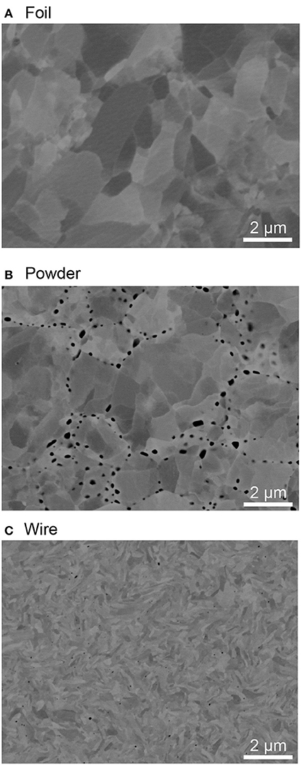
Figure 1. Back-scattered electron (BSE) image of the bcc iron starting materials; (A) foil, (B) sintered and deformed powder, and (C) wire. These images were obtained using a scanning electron microscope equipped with a field emission gun (FE-SEM, JEO JSM-7000F) with accelerating voltage of 10 kV and probe current of 8 nA. Observed cross sections are normal to compression axis in the subsequent DAC experiments. Contrast in gray area is orientation contrast in iron whereas black dots in (B) are iron oxide.
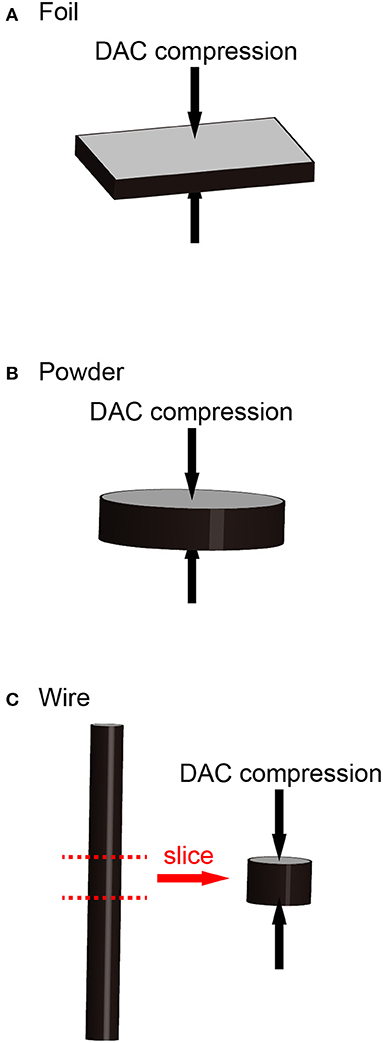
Figure 2. Schematics of iron starting materials. Black arrows indicate the compressional direction of a DAC. (A) Iron foil with initial thickness of 10 μm. (B) Iron powder that was sintered in a D-DIA apparatus at 2 GPa and 600°C for 1 h, then deformed uniaxially with approximate strain rate of 2 × 10⁻⁵ s−1 at room temperature. (C) Iron wire (100 μm in diameter) was sliced to about 10 μm thick.
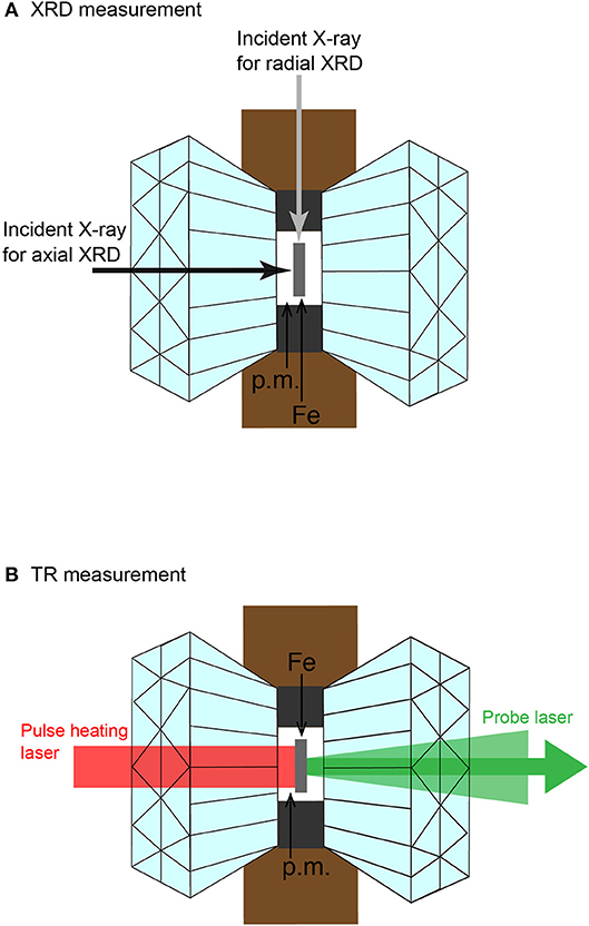
Figure 3. Schematics of the experiment. (A) Directions of incident X-ray for axial and radial XRD measurements. (B) Ray paths of laser beams for thermoreflectance measurements in a DAC. p.m. indicates pressure transmitting medium.
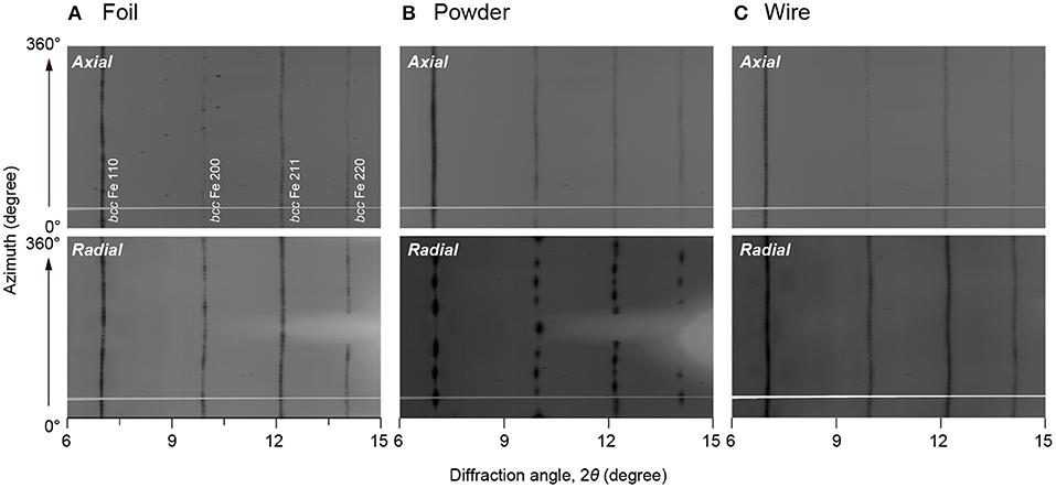
Figure 4. Unrolled XRD images of iron starting materials, (A) foil, (B) sintered powder, and (C) wire obtained at 1 bar. Upper panels show XRD images obtained from the axial geometry, and lower panels are the radial XRD images. Miller indices of bcc iron are shown in the upper left panel. Horizontal gray line in each image is a shadow of beam stopper holder. Wavelength of incident X-ray was 0.247 Å.
For phase identification and texture analyses, angle-dispersive two-dimensional XRD measurements were conducted on the iron samples in a DAC at BL10XU, SPring-8. The wavelengths of the monochromatic incident X-ray beam were 0.247~0.413 Å (30~50 keV) and the incident X-ray was collimated to about 10 μm in diameter. The XRD images were recorded on an imaging plate (IP) detector (RIGAKU R-AXIS V++) with a typical exposure time of 30 s. The XRD data for the iron sample in a DAC were collected in both axial and radial diffraction geometries where the sample is irradiated with X-rays both parallel and perpendicular to the DAC compression axis, respectively, in order to increase pole figure coverage (Figure 3A). In runs 1 and 4, only the axial XRD spectrum was collected. Pressures were determined by using an equation of state (EOS) of hcp iron (Yamazaki et al., 2012).
Axial and radial XRD images were quantitatively analyzed for determination of CPO using the Rietveld method as implemented in the software package MAUD (Lutterotti et al., 2014). First, the XRD images were integrated from 0° to 360° azimuth angles over 5° sectors to produce 72 patterns (Figure 4). Sample to the IP distance, wavelength of incident X-ray, and the IP geometry were calibrated with CeO2 standard. The sample CPO is calculated by the E-WIMV algorithm to produce an orientation distribution function (ODF) with a resolution of 15°. No symmetry constraint was applied in the analysis.
Thermal conductivity (κ) is a function of thermal diffusivity (D), density (ρ), and isobaric heat capacity (CP): κ = DρCP. The D of hcp iron at high P was measured by means of the pulsed light heating thermoreflectance technique in a DAC at Tokyo Institute of Technology (Figure 3B). Details of the measurement system and the analytical methods of this technique have been described in the literature (Yagi et al., 2011; Ohta et al., 2017). The density (ρ) of hcp iron was determined from the present XRD data. The isobaric specific heat capacity (CP) was calculated from the thermodynamic relations and the reported thermoelastic parameters of hcp iron (Yamazaki et al., 2012).
Prior to the high-P experiments, we investigated the CPO of bcc iron starting materials loaded into a DAC at ambient conditions. Figure 4 presents the variations in the diffraction intensity for (110), (200), (211), and (220) diffractions of the three-types of bcc iron starting material. We used these four XRD peaks for texture analyses with the MAUD program, and acquired pole figures of the bcc samples (Figure 5). Pole densities are expressed in multiples of random distribution (m.r.d.). The bcc iron foil showed a single crystal-like CPO with an alignment of <111> along its compression axis and an alignment of <110> on the radial plane (Figure 5A). Since the foil included large grains, as shown in Figure 1A, the number of grains in a diffraction volume might be limited. This would be the reason for the single crystal-like CPO of this sample. Although the CPO of bcc iron foil was only determined in Run 3, the CPO could be entirely different in each run due to the limited number of grains in a sample volume of a DAC experiment. The sintered and deformed bcc iron powder showed an almost axi-symmetric CPO pattern with concentrations of <100> and <111> along its compression axis (Figure 5B). This is consistent with reports by Merkel et al. (2004) and Nishihara et al. (2018), where similar CPO was formed by uniaxial compression of randomly textured bcc iron. The bcc iron wire had an almost random texture as shown in Figure 5C.
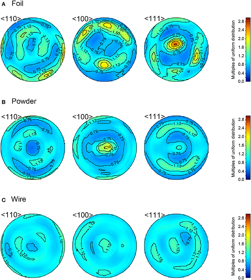
Figure 5. Pole figures of (A) foil, (B) powder, and (C) wire of bcc iron starting materials at ambient conditions showing the variation in the crystallographic orientation of the <110>, < 100>, and <111> directions. The direction of a DAC compression is in the center of the pole figure.
The polycrystalline bcc iron starting materials loaded into a DAC were squeezed to transform them into hcp iron. In all eight runs, we collected XRD data for hcp iron and obtained their CPO patterns. Figure 6 shows the representative XRD data for hcp iron obtained at 41.6 GPa in both axial and radial geometries. Five XRD peaks from the (100), (0002), (101), (102), and (110) diffractions were used for texture analyses. The obtained pole figures of hcp iron clearly show that the CPO of hcp iron differs depending on the texture of the starting materials (Figure 7). The CPO of hcp phase derived from powder bcc iron is characterized by an alignment of <110> parallel to the compression axis and <0001> on the radial plane (Figure 6B). This is largely consistent with the Burgers orientation relationship, {110}bcc//{0001}hcp and <111>bcc// <110>hcp, for a martensitic transformation between bcc and hcp phases. The orientation of <0001> is not axi-symmetric, but lies along a particular direction (Figure 7B); although the orientation of <110> in the bcc starting material is nearly axi-symmetric (Figure 5B). This is presumably due to strong variant selection in the bcc to hcp phase transformation under high deviatoric stress in a DAC. The CPO pattern of hcp iron from bcc wire is characterized by a strong concentration of <0001> parallel to its compression axis (Figure 7C), and this pattern is accompanied by a weaker concentration of <0001> along the radial direction at lower P (Run 1). This observation is reasonably interpreted as follows. The <111> (and <100>) is aligned parallel to the compression axis from initial random texture by compression of bcc phase at low pressure. The bcc to hcp phase transformation yields an alignment of <0001> along the radial direction following the Burgers relationship, and subsequent uniaxial compression to higher pressure gradually aligns <0001> along the compression axis through the basal slip dominant viscous creep (e.g., Merkel et al., 2004; Nishihara et al., 2018). In hcp iron that was transformed from bcc foil, completely different CPO patterns were observed depending on the run: <100> was aligned along the compression axis in Runs 2 and 7 (Figure 7A), whereas <0001> was aligned along the compression axis in Runs 3 and 4. This is probably because the CPO of bcc iron foil was different in each run due to its large grain size (Figure 1A). However, the CPO of the bcc phase is not perfectly inherited by the hcp phase along with the Burgers orientation relationship. In reality, the situation is complicated by the existence of internal stresses between grains that develop during the phase transformation. They also influence the orientation relations and variant selection and their effects cannot be deduced from simple crystallographic considerations.
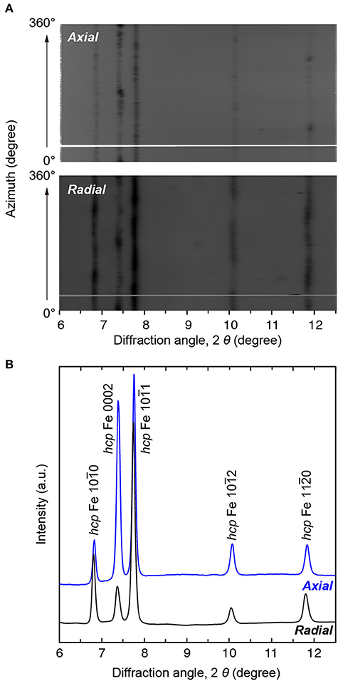
Figure 6. XRD patterns of hcp iron obtained at 41.6 GPa and 300 K in Run #7. (A) Unrolled XRD images of hcp iron measured in axial (upper panel) and radial (lower panel) geometries. (B) Integrated XRD patterns of hcp iron measured in axial (blue) and radial (black) geometries. Wavelength of incident X-ray was 0.247 Å.
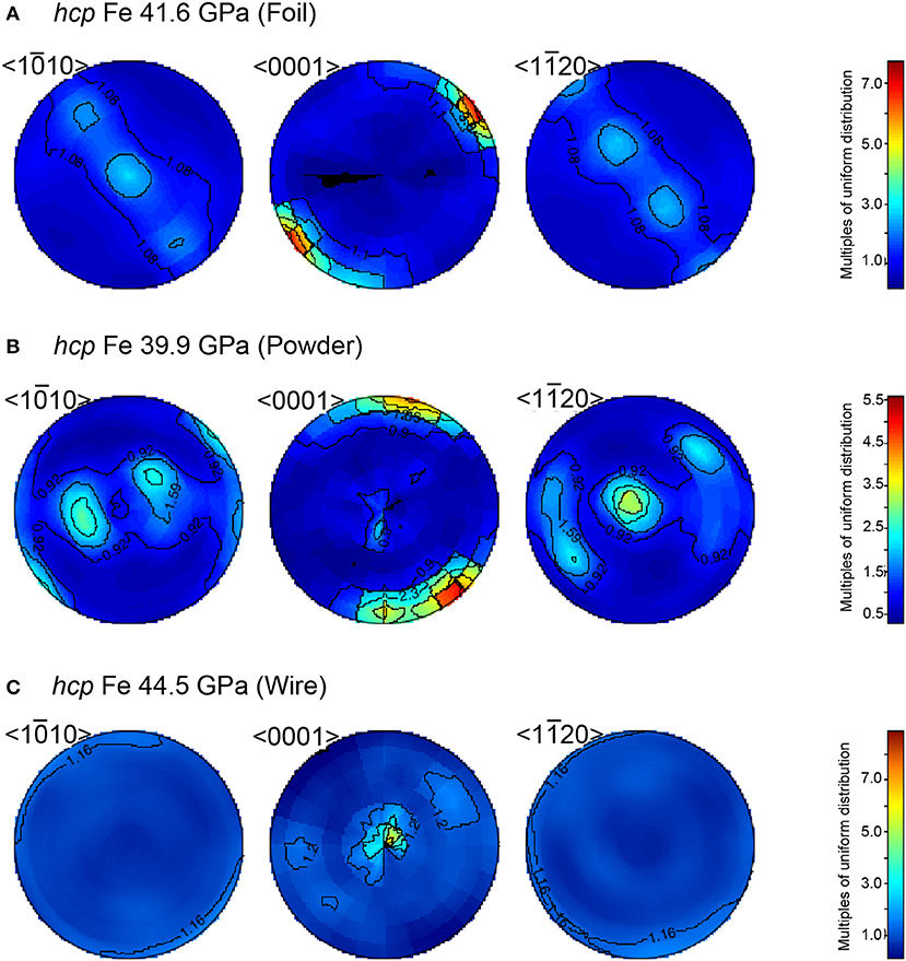
Figure 7. Pole figures of hcp iron showing the variation in the crystallographic orientation of the <100>, <0001>, and <110> directions. (A) hcp iron at 41.6 GPa transformed from bcc iron foil. (B) hcp iron at 39.9 GPa synthesized from sintered powder sample. (C) hcp iron at 44.5 GPa that was made from bcc iron wire. The direction of a DAC compression is in the center of the pole figure.
Figure 8 indicates the emergence distributions of crystals with angle θ between the DAC compression axis and <0001> of hcp iron, which means the frequency of hcp iron grains with angles between the c axis and compressional axis. This was calculated from <0001> pole figure (hence from ODF), and a distribution is normalized such that its integration in the hole interval to be unity.
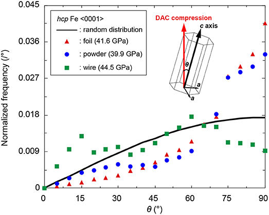
Figure 8. Distribution of angle between <0001> and DAC compression axis in three hcp iron samples. Red triangles; hcp iron from foil starting material, blue circles; hcp iron from sintered powder, green squares; hcp iron from wire sample. Black line shows randomly oriented hcp iron. θ is defined as an angle between DAC compression direction and c axis of hcp iron (inset).
After the XRD experiments and the subsequent CPO analyses, we measured high-P thermal conductivity of the polycrystalline hcp iron by means of the pulsed light heating thermoreflectance technique (Table 1). The transient temperature change in a hcp iron sample by pulse laser heating was recorded at high P as shown in Figure 9A. The obtained temperature history curve was analyzed considering the one-dimensional heat diffusion in iron and pressure medium (SiO2 glass):
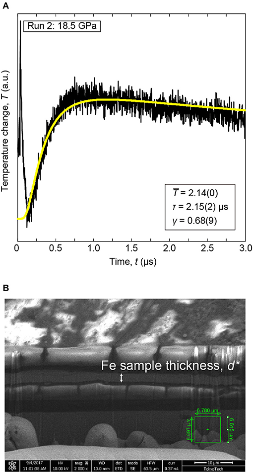
Figure 9. Representatives of (A) Transient temperature curve of hcp iron obtained at 18.5 GPa and 300 K (Run #2) and (B) SEM image of a cross section of the recovered sample prepared by the FIB apparatus. The transient temperature curve was fitted by Equation (2) (yellow curve). In this case, we set n = 5. The obtained fitting parameters are shown in (A). Note that this SEM image has been acquired from an oblique direction to sample stage, and thus the apparent thickness shown in this figure is different from the actual sample thickness.
where T(t) is temperature, is a constant, t is time, and γ expresses heat effusion to pressure medium (Yagi et al., 2011). τ is the heat diffusion time across the iron sample. We obtained , γ, and τ by fitting the measured curves to Equation (2). The sample thickness (d) was measured in a sample recovered from the DAC. Its cross section was prepared by using the focused ion beam (FIB) apparatus, and the thickness of the iron sample was measured under a scanning microscope (SEM) (Figure 9B). The effect of lattice volume expansion due to decompression and transformation from hcp to bcc phase was corrected to determine d by using the EOSs of hcp iron (Yamazaki et al., 2012). The τ and d gives high-P thermal diffusivity;
Multiplication of the D, ρ, and CP yields the high-P thermal conductivity of hcp iron.
The obtained thermal conductivity of hcp iron at high P and 300 K is shown in Figure 10. The hcp iron samples from the wire starting material show higher conductivity than those from the foil and powder samples at similar pressures. The aforementioned CPO analyses showed that hcp iron from bcc wire shows a strong orientation of <0001> parallel to the compression axis, while hcp iron from powder and foil tends to show an alignment of <0001> on the radial plane. This CPO information and polycrystalline hcp iron conductivity imply that the thermal conductivity of hcp iron along the c axis (κc) is higher than that along the a axis (κa). For comparison, we calculated high-P/room-T κel of polycrystalline hcp iron from the reported electrical resistivity (Gomi et al., 2013) and the Wiedemann-Franz law with the L0 (Equation 1) (Figure 10). The present values of thermal conductivity of hcp iron are about half of the calculated κel. Such a difference could be due to anisotropy in the thermal conductivity of hcp iron because (Gomi et al., 2013) measured the high-P resistivity during decompression after squeezing the iron foil up to 100 GPa at 300 K. The measurement direction of the high-P resistivity was perpendicular to that of the present thermal conductivity. Since all the compared data are at 300 K, the influence of electron-electron scattering on thermal conductivity should be negligible (Pourovskii et al., 2017).
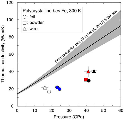
Figure 10. Thermal conductivity of polycrystalline hcp iron as a function of P at 300 K. The hcp iron samples were synthesized from foil (circles), powder (square), and wire (triangles) starting materials. Black line with gray band shows κel of hcp iron calculated from the resistivity of hcp iron (Gomi et al., 2013) and the Wiedemann-Franz (WF) law (Equation 1). The present conductivity data were obtained along DAC compression axis, while the resistivity of hcp iron (Gomi et al., 2013) was measured along the direction normal to DAC compression. Pairs of symbols with same color show similar pressure and were used to calculate the anisotropy in thermal conductivity.
Here we quantitatively evaluate the anisotropy in the crystallographic thermal conductivity of hcp iron single crystal based on the present results of CPO analyses and thermal conductivity measurements (Figures 7, 8, 10). The thermal conductivity of polycrystalline hcp iron we measured can be regarded as the effective thermal conductivity of a hcp iron single crystal aggregate along the obtained CPO (Figure 10). First, we define the effective thermal conductivity of a hcp crystal along a direction θ (κ(θ)) as follows:
where θ is an angle between the heat flow direction and the c axis (Figure 8 inset) (see Appendix). In this study, the heat flow direction is parallel to the DAC compression direction (Figure 3B). Then, we calculated the anisotropy in thermal conductivity of a hcp iron crystal assuming two-types of κ(θ) mixing model as described below.
We consider a layered structure in which each layer consists of hcp iron crystals having the same θ value. When the heat flow and DAC compression directions are perpendicular to the stacking direction, the effective thermal conductivity of the layered hcp iron aggregate along the heat flux can be expressed by an equivalent equation of the parallel resistor model (Figure 11A inset):
where κparallel is an effective thermal conductivity assuming the parallel model and p(θ) is the emergence distribution of angles between the <0001> axis and heat flow (DAC compression) direction (e.g., Figure 8). When the heat flow (DAC compression) direction is parallel to the stacking direction, the effective thermal conductivity can be regarded as the series resistor model (Figure 11B inset):
where κseries denotes an effective thermal conductivity considering the series model. Using these models (Equations 4–6) and pairs of the present thermal conductivity of polycrystalline hcp iron at similar P, we found the κa and κc of hcp iron at high P (Table 2 and Figures 11A,B). Based on the mixing theory (Guéguen and Palciauskas, 1994), the solution of the parallel model gives the lower limit, while the series model provides the upper bound limit. The results clearly indicate anisotropy in the single crystal thermal conductivity of hcp iron.
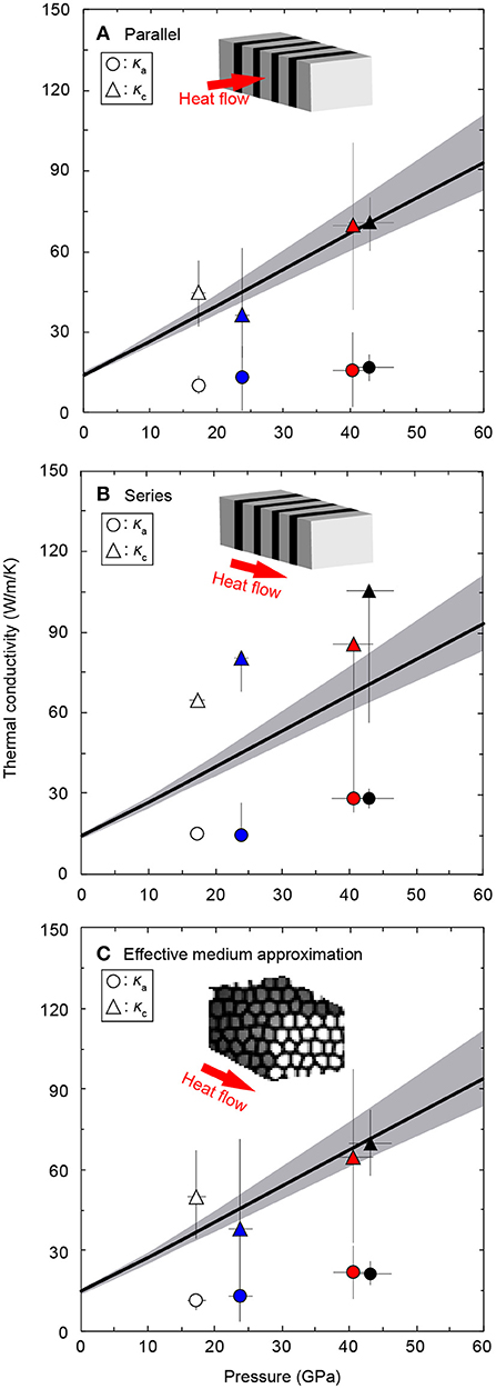
Figure 11. Thermal conductivities of single crystal hcp iron along a and c axes (κa and κc) as a function of P at 300 K. (A) Solutions of the parallel model (Equation 5). (B) The series model solutions (Equation 6). (C) Random distribution model calculated by the effective medium approximation (Equation 7) (Landauer, 1952). Circles; κa, triangles; κc. Black line with gray band is κel of hcp iron as shown in Figure 10. Inset figures show schematic illustrations of the parallel, series, and random models, respectively.
The solutions of the parallel model indicate that κc is about four-fold higher than κa. And, the values of κc are comparable to the κel of hcp iron from the electrical resistivity data reported by Gomi et al. (2013) (Figure 11A). The series model also shows a similar trend, although the absolute values of the κa and κc are different from the solutions of the parallel model (Figure 11B).
This is a realistic case in which each hcp iron crystal with the same orientation (i.e., the same θ) is randomly distributed in the polycrystalline aggregate sample, rather than forming the laminated structure considered above (Figure 11C inset). We thus employ effective medium approximation to calculate the thermal conductivity anisotropy in a hcp iron crystal that is randomly distributed in polycrystal (Landauer, 1952):
where κrandom, κi, and vi are the effective thermal conductivity assuming a random texture, thermal conductivity of i component, and its volume fraction, respectively. As well as the parallel and series models, the effective medium approximation also shows strong anisotropy in the single crystal thermal conductivity of hcp iron (Figure 11C). In this case, the κc is about three times as high as κa, at least up to 43.1 GPa.
All the crystal mixing models indicate strong anisotropy in the thermal conductivity of hcp iron at high P and room T (Table 2 and Figure 11). The obtained results of κc of hcp iron are comparable or higher than the κel (Gomi et al., 2013), indicating that the thermal and electrical conductivity of polycrystalline hcp iron would show variation up to a factor of four, depending on the CPO of the hcp iron sample in a DAC. Indeed, the measured electrical resistivities (or resistance) of hcp iron show considerable variation, especially at the onset of bcc-hcp transition that is about 13 GPa, but all of the experimental data obtained above 40 GPa are consistent with each other (Reichlin, 1983; Jaccard et al., 2002; Deng et al., 2013; Gomi et al., 2013; Seagle et al., 2013; Zhang et al., 2018). The discrepancy among them could be derived from difference in CPO of hcp iron samples just after the transition, since they have used various types of bcc iron starting materials. The CPO of such samples might become similar due to uniaxial compression of the DAC, resulting in similar resistivity values at higher P. Although Secco and Balog (2001) have selected Gd as the best analog material to predict the anisotropy in the conductivity of hcp iron, the electrical conductivity of Gd along the c axis is only 30% larger than that along the a axis at ambient conditions.
However, note that the strength of conductivity anisotropy obtained above highly depends on the strength of the CPO determined based on the XRD data. The ODF (and hence CPO) in this study was calculated using the E-WIMV algorithm, which is an improved version of WIMV. Determination of the ODF is a kind of inversion which does not have a unique solution, and WIMV algorithm (as well as E-WIMV) gives the smoothest positive solution with maximum entropy for ODF (Kocks et al., 2000; Lutterotti et al., 2007). This means that the CPO determined from XRD data with a limited pole figure coverage gives a lower bound in texture strength. Therefore, the single crystal thermal conductivity anisotropy of hcp iron presented in this study is considered to be the upper bound and the real anisotropy might be smaller.
An open question raised above is whether the discrepancy in experimentally determined thermal conductivity of iron at the core conditions can be explained by anisotropy in the conductivity of single crystal hcp iron (Konôpková et al., 2016; Ohta et al., 2016). As a matter of fact, both studies did not determine the room-T conductivity of iron from their own experiments. Ohta et al. (2016) measured T dependence of electrical resistance of iron samples at high P and referred to the high-P/room-T resistivity of hcp iron from Gomi et al. (2013) to calculate high-P/high-T resistivity. The κel of hcp iron at 135 GPa and 300 K was obtained as 165(+56/−22) W/m/K. The method employed in Konôpková et al. (2016) cannot determine high-P/room-T conductivity in principle, as they acquired time-dependent thermal radiation spectra from a laser-heated iron sample. To construct a model of high-P/high-T thermal conductivity of hcp iron, they referred to a value of electrical resistivity of hcp iron at 135 GPa and 300 K inferred from the experimental results of Seagle et al. (2013) and converted it to κel of 120(+20/−30) W/m/K via the Wiedemann-Franz law with an unusual Lorenz number of 1.9 × 10⁻⁸ WΩ/K2. In this study, we found highly anisotropic thermal conductivity of hcp iron at least up to 44.5 GPa and 300 K based on the present XRD and thermal conductivity measurements. Based on the pressure derivatives () of the obtained κa and κc of hcp iron that are 0.43 and 0.98 W/m/K/GPa, respectively, we estimated κa and κc of hcp iron at higher P, indicating the anisotropy in the conductivity is maintained to the core pressures (Figure 12). At 135 GPa, the pressure of the Earth's core-mantle boundary, κa and κc of hcp iron are 61.4 ± 8.9 and 157.3 ± 72.6 W/m/K, respectively, and κc/κa is 2.6. Therefore, thermal conductivity anisotropy in single crystal hcp iron can explain the discrepancy in the reference conductivities at 135 GPa and 300 K (Figure 12). However, the reported values of the thermal conductivity of hcp iron at 135 GPa and high T conditions shows about a seven-fold difference (Konôpková et al., 2016; Ohta et al., 2016). It remains unclear whether the conductivity anisotropy of single crystal hcp iron is kept to a few thousand K. In some hcp analog metals, their κc/κa was getting smaller with increasing T (Nellis and Legvold, 1969; Alderson and Hurd, 1975; Secco and Balog, 2001). Only for magnesium, its κc/κa increases with increasing T, but the T response of κc/κa was examined only from 3 to 300 K. Unless hcp iron shows strongly positive T dependence of κc/κa, the conductivity anisotropy is unlikely to be the main cause of the controversial reports (Konôpková et al., 2016; Ohta et al., 2016). In this context, T enhanced electron-electron scattering in compressed iron would be a key factor as shown in Pourovskii et al. (2017). Within their calculations, the thermal conductivity is depressed by 39% by electron-electron scattering. For more detailed discussion, further studies for direct determination of both electrical and thermal conductivities are required at extremely high P-T conditions.
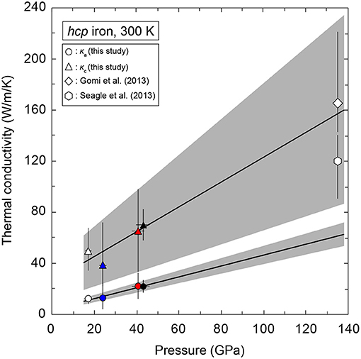
Figure 12. Linear extrapolation of the obtained κa and κc at 300 K. Values of κel of hcp iron at 135 GPa and 300 K are also plotted that were estimated from the resistivity of hcp iron (Gomi et al., 2013) and the WF law with L0 (open diamond), and from the hcp iron resistivity (Seagle et al., 2013) and the WF law with L = 1.9 × 10⁻⁸ WΩ/K2 (open hexagon).
If the thermal conductivity anisotropy in hcp iron single crystal is preserved to the Earth's inner core conditions, it may have important implications for evolution and dynamics there. The seismological exploration of the Earth's inner core has revealed its structural complexities (e.g., Tkalčić, 2015; Romanowicz and Wenk, 2017). One of the main features in the inner core is that a seismic wave along the polar direction propagates by about 3% faster than one along the equatorial direction (Poupinet et al., 1983; Morelli et al., 1986). The preferred alignment of hcp iron alloy crystals with the c axis parallel to the fast-seismic axis has been repeatedly suggested to explain the cause of the seismic anisotropy in the inner core (Yoshida et al., 1996; Bergman, 1997; Karato, 1999; Buffett and Wenk, 2001), although a consensus has not reached among theoretical studies to calculate sound velocity difference between a and c axes of hcp iron. Early theoretical calculations at 0 K showed that c axis was the faster direction than a axis in hcp iron (e.g., Stixrude and Cohen, 1995), but later studies at high temperatures showed that the sense of anisotropy changes, and the a axis becomes the fast direction (Steinle-Neumann et al., 2001), or nearly isotropic (Sha and Cohen, 2010). If the c axis of hcp iron alloy preferentially aligns along the Earth's rotational axis in the inner core, strong anisotropy of the thermal conductivity in hcp iron as observed in this study implies an anisotropic thermal conductivity of the inner core with higher conductivity in the polar direction and lower conductivity in equatorial radial directions. In addition, recent first-principles calculations showed that incorporation of silicon and nickel into iron enhances anisotropy in the conductivity (Gomi et al., 2016). The Taylor column type outer core convection extracts more heat away from the ICB in equatorial regions than in polar regions, even in the absence of anisotropic thermal conductivity. As a result, greater heat loss and lower thermal conductivity of the inner core along the equatorial direction than the polar direction would produce large temperature heterogeneity at the ICB, which would enhance the directionality of inner core growth and keep the crystallographic origin of the inner core anisotropy through the geological timescale via the plastic core flow mechanism (Yoshida et al., 1996). In the recent years, detailed modeling of the inner core evolution and dynamics have been reported, but no study considered the thermal conductivity anisotropy in the inner core (e.g., Alboussière and Deguen, 2012; Deguen, 2012). The magnitude of thermal conductivity anisotropy in hcp iron (iron alloy) at the ICB conditions needs to be confirmed for more detailed discussion about the inner core evolution and dynamics.
In this paper, we presented the results from the synchrotron XRD experiments and the thermal conductivity measurements on polycrystalline hcp iron up to 44.5 GPa and 300 K. Analyses of the XRD data yielded the CPO of hcp iron samples, which revealed variable CPO of hcp iron depending on the CPO of bcc iron starting materials. The obtained CPO information and thermal conductivity value of hcp iron samples were used to evaluate the anisotropy in the thermal conductivity of hcp iron single crystal. Assuming a randomly distributed aggregate texture in hcp iron polycrystal, we found κc/κa ~ 3 at 44.5 GPa and 300 K. Such strong anisotropy could be maintained to the Earth's core conditions and cause the discrepancy between recent experimental determinations of the thermal conductivity of hcp iron. Thermal conductivity anisotropy of hcp iron under Earth's actual core conditions should thus be investigated in future work to provide tighter constraints on the thermal evolution and dynamics of Earth's core and mantle.
KO and YN are responsible for project design and wrote the manuscript. KO, YN, and YS are responsible for sample preparation, XRD experiments, and texture analyses. KO and TY are responsible for thermal conductivity measurements. KH, SK, NH, and YO helped with XRD experiments at BL10XU, SPring-8. All authors contributed to the discussion and final manuscript.
This work was supported by JSPS KAKENHI (grant number 26247075, 15H03749, and 17H04861) and the Joint Usage/Research Center PRIUS, Ehime University.
The authors declare that the research was conducted in the absence of any commercial or financial relationships that could be construed as a potential conflict of interest.
We thank S. Arakawa for discussion about the calculation of thermal conductivity anisotropy. Synchrotron XRD measurements were conducted at BL10XU, SPring-8 (proposal numbers 2016B0080 and 2017A0072).
Alboussière, T., and Deguen, R. (2012). Asymmetric dynamics of the inner core and impact on the outer core. J. Geodyn. 61, 172–182. doi: 10.1016/j.jog.2012.07.006
Alderson, J. E. A., and Hurd, C. M. (1975). Anisotropic temperature-dependent resistivity of Cd, Zn, and Mg. Phys. Rev. B 12, 501–508. doi: 10.1103/PhysRevB.12.501
Badro, J., Siebert, J., and Nimmo, F. (2016). An early geodynamo driven by exsolution of mantle components from Earth's core. Nature 536, 326–328. doi: 10.1038/nature18594
Balog, P., and Secco, R. (1999). Electrical resistivity anisotropy of gd at high pressure. Phys. Status Solid B 214, 357–363.
Bergman, M. (1997). Measurements of electric anisotropy due to solidification texturing and the implications for the Earth's inner core. Nature 389, 60–63.
Biggin, A., Piispa, E., Pesonen, L., Holme, R., Paterson, G., Veikkolainen, T., et al. (2015). Palaeomagnetic field intensity variations suggest Mesoproterozoic inner-core nucleation. Nature 526, 245–248. doi: 10.1038/nature15523
Braginsky, S. I. (1963). Structure of the F layer and reasons for convection in the Earth's core. Sov. Phys. Dokl. 149, 8–10.
Buffett, B. A., and Wenk, H. R. (2001). Texturing of the Earth's inner core by Maxwell stresses. Nature 413, 60–63. doi: 10.1038/35092543
Deguen, R. (2012). Structure and dynamics of Earth's inner core. Earth Planet. Sci. Lett. 333, 211–225. doi: 10.1016/j.epsl.2012.04.038
Deng, L., Seagle, C., Fei, Y., and Shahar, A. (2013). High pressure and temperature electrical resistivity of iron and implications for planetary cores. Geophys. Res. Lett. 40, 33–37. doi: 10.1029/2012GL054347
Dewaele, A., Denoual, C., Anzellini, S., Occelli, F., Mezouar, M., Cordier, P., et al. (2015). Mechanism of the α-ε phase transformation in iron. Phys. Rev. B 91:174105. doi: 10.1103/PhysRevB.91.174105
Du, Z., Jackson, C., Bennett, N., Driscoll, P., Deng, J., Lee, K., et al. (2017). Insufficient energy from MgO exsolution to power early geodynamo. Geophys. Res. Lett. 44, 11376–11381. doi: 10.1002/2017GL075283
Gomi, H., Hirose, K., Akai, H., and Fei, Y. (2016). Electrical resistivity of substitutionally disordered hcp Fe–Si and Fe–Ni alloys: chemically-induced resistivity saturation in the Earth's core. Earth Planet. Sci. Lett. 451, 51–61. doi: 10.1016/j.epsl.2016.07.011
Gomi, H., Ohta, K., Hirose, K., Labrosse, S., Caracas, R., Verstraete, M., et al. (2013). The high conductivity of iron and thermal evolution of the Earth's core. Phys. Earth Planet. Interiors 224, 88–103. doi: 10.1016/j.pepi.2013.07.010
Guéguen, Y., and Palciauskas, V. (1994). Introduction to the Physics of Rocks. Princeton, NJ: Princeton University Press.
Hall, P. M., Legvold, S., and Review, S.-F. (1959). Electrical resistivity of yttrium single crystals. Phys. Rev. 116, 1446–1447. doi: 10.1103/PhysRev.116.1446
Hirose, K., Morard, G., Sinmyo, R., Umemoto, K., Hernlund, J., Helffrich, G., et al. (2017). Crystallization of silicon dioxide and compositional evolution of the Earth's core. Nature 543, 99–102. doi: 10.1038/nature21367
Ishimatsu, N., Sata, Y., Maruyama, H., Watanuki, T., Kawamura, N., Mizumaki, M., et al. (2014). α-ε transition pathway of iron under quasihydrostatic pressure conditions. Phys. Rev. B 90, 014422. doi: 10.1103/PhysRevB.90.014422
Jaccard, D., Holmes, A. T., Behr, G., Inada, Y., and Onuki, Y. (2002). Superconductivity of ε-Fe: complete resistive transition. Phys. Lett. A 299, 282–286. doi: 10.1016/S0375-9601(02)00725-9
Karato, S. (1999). Seismic anisotropy of the Earth's inner core resulting from flow induced by Maxwell stresses. Nature 402, 871–873. doi: 10.1038/47235
Kocks, U. F., Tomé, C. N., and Wenk, H. R. (2000). Texture and Anisotropy: Preferred Orientations in Polycrystals and Their Effect on Materials Properties. Cambridge, UK: Cambridge University Press.
Konôpková, Z., McWilliams, R., Gómez-Pérez, N., and Goncharov, A. (2016). Direct measurement of thermal conductivity in solid iron at planetary core conditions. Nature 534, 99–101. doi: 10.1038/nature18009
Landauer, R. (1952). The electrical resistance of binary metallic mixtures. J. Appl. Phys. 23, 779–784. doi: 10.1063/1.1702301
Landeau, M., Aubert, J., and Olson, P. (2017). The signature of inner-core nucleation on the geodynamo. Earth Planet. Sci. Lett. 465, 193–204. doi: 10.1016/j.epsl.2017.02.004
Lister, J. (2003). Expressions for the dissipation driven by convection in the Earth's core. Phys. Earth Planet. Interiors 140, 145–158. doi: 10.1016/j.pepi.2003.07.007
Lutterotti, L., Bortolotti, M., Ischia, G., Lonardelli, I., and Wenk, H. R. (2007). Rietveld texture analysis from diffraction images. Z. Kristallogr. Suppl. 26, 125–130. doi: 10.1524/zksu.2007.2007.suppl_26.125
Lutterotti, L., Vasin, R., and Wenk, H.-R. (2014). Rietveld texture analysis from synchrotron diffraction images. I. Calibration and basic analysis. Powder Diff. 29, 76–84. doi: 10.1017/S0885715613001346
Merkel, S., Wenk, H.-R., Gillet, P., Mao, H., and Hemley, R. (2004). Deformation of polycrystalline iron up to 30 GPa and 1000 K. Phys. Earth Planet. Interiors 145, 239–251. doi: 10.1016/j.pepi.2004.04.001
Merkel, S., and Yagi, T. (2005). X-ray transparent gasket for diamond anvil cell high pressure experiments. Rev. Sci. Instrum. 76:046109. doi: 10.1063/1.1884195
Miyagi, L., Kunz, M., Knight, J., Nasiatka, J., Voltolini, M., and Wenk, H.-R. (2008). In situ phase transformation and deformation of iron at high pressure and temperature. J. Appl. Phys. 104:103510. doi: 10.1063/1.3008035
Morelli, A., Dziewonski, A., and Woodhouse, J. (1986). Anisotropy of the inner core inferred from PKIKP travel times, Geophys. Res. Lett. 13, 1545–1548. doi: 10.1029/GL013i013p01545
Nellis, W. J., and Legvold, S. (1969). Thermal conductivities and Lorenz functions of gadolinium, terbium, and holmium single crystals. Phys. Rev. 180, 581–590. doi: 10.1103/PhysRev.180.581
Nishihara, Y., Ohuchi, T., Kawazoe, T., Seto, Y., Maruyama, G., Higo, Y., et al. (2018). Deformation-induced crystallographic-preferred orientation of hcp-iron: an experimental study using a deformation-DIA apparatus. Earth Planet. Sci. Lett. 490, 151–160. doi: 10.1016/j.epsl.2018.03.029
Ohta, K., Kuwayama, Y., Hirose, K., Shimizu, K., and Ohishi, Y. (2016). Experimental determination of the electrical resistivity of iron at Earth's core conditions. Nature 534, 95–98. doi: 10.1038/nature17957
Ohta, K., Yagi, T., Hirose, K., and Ohishi, Y. (2017). Thermal conductivity of ferropericlase in the Earth's lower mantle. Earth Planet. Sci. Lett. 465, 29–37. doi: 10.1016/j.epsl.2017.02.030
O'Rourke, J., and Stevenson, D. (2016). Powering Earth's dynamo with magnesium precipitation from the core. Nature 529, 387–389. doi: 10.1038/nature16495
Poupinet, G., Pillet, R., and Souriau, A. (1983). Possible heterogeneity of the Earth's core deduced from PKIKP travel times. Nature 305, 204–206.
Pourovskii, L., Mravlje, J., Georges, A., Simak, S., and Abrikosov, I. (2017). Electron–electron scattering and thermal conductivity of f P travel timess core conditions. New J. Phys. 19:073022. doi: 10.1088/1367-2630/aa76c9
Reichlin, R. (1983). Measuring the electrical resistance of metals to 40 GPa in the diamond-anvil cell. Rev. Sci. Instrum. 54, 1674–1677 doi: 10.1063/1.1137308
Romanowicz, B., and Wenk, H. R. (2017). Anisotropy in the deep Earth. Phys. Earth Planet. Interiors 269, 58–90. doi: 10.1016/j.pepi.2017.05.005
Sanborn, B. A., Allen, P. B., and Papaconstantopoulos, D. A. (1989). Empirical electron-phonon coupling constants and anisotropic electrical resistivity in hcp metals. Phys. Rev. B 40, 6037–6044. doi: 10.1103/PhysRevB.40.6037
Seagle, C., Cottrell, E., Fei, Y., Hummer, D., and Prakapenka, V. (2013). Electrical and thermal transport properties of iron and iron-silicon alloy at high pressure. Geophys. Res. Lett. 28, 5377–5381. doi: 10.1002/2013GL057930
Secco, R. (2017). Thermal conductivity and Seebeck coefficient of Fe and Fe-Si alloys: Implications for variable Lorenz number. Phys. Earth Planet. Interiors 265, 23–34. doi: 10.1016/j.pepi.2017.01.005
Secco, R. A., and Balog, P. S. (2001). On the possibility of anisotropic heat flow in the inner core. Can. J. Earth Sci. 38, 975–982. doi: 10.1139/e00-116
Sha, X., and Cohen, R. (2010). Elastic isotropy of ε-Fe under Earth's core conditions. Geophys. Res. Lett. 37:L10302. doi: 10.1029/2009GL042224
Smirnov, A., Tarduno, J., Kulakov, E., McEnroe, S., and Bono, R. (2016). Palaeointensity, core thermal conductivity and the unknown age of the inner core. Geophys. J. Int. 205, 1190–1195. doi: 10.1093/gji/ggw080
Spedding, F., Cress, D., and Beaudry, B. (1971). The resistivity of scandium single crystals. J. Less Common Metals 23, 263–270. doi: 10.1016/0022-5088(71)90140-8
Steinle-Neumann, G., Stixrude, L., Cohen, R., and Gülseren, O. (2001). Elasticity of iron at the temperature of the Earth's inner core. Nature 413, 57–60. doi: 10.1038/35092536
Stierman, R. J., Gschneidner, K. A., Tsang, T.-W. E., Schmidt, F. A., Klavins, P., Shelton, R. N., et al. (1983). Magnetic susceptibility and electrical resistivity of electrotransport purified scandium single crystals from l resistivity J. Magn. Magn. Mater. 36, 249–254. doi: 10.1016/0304-8853(83)90122-1
Stixrude, L., and Cohen, R. E. (1995). High-pressure elasticity of iron and anisotropy of Earth's inner core. Science 267, 1972–1975.
Tkalčić, H. (2015). Complex inner core of the Earth: the last frontier of global seismology. Rev. Geophys. 53, 59–94. doi: 10.1002/2014RG000469
Williams, Q. (2018). The thermal conductivity of Earth's core: a key geophysical parameter's constrains and uncertainties. Annu. Rev. Earth Planet. Sci. 46, 47–66. doi: 10.1146/annurev-earth-082517-01015
Yagi, T., Ohta, K., Kobayashi, K., Taketoshi, N., Hirose, K., and Baba, T. (2011). Thermal diffusivity measurement in a diamond anvil cell using a light pulse thermoreflectance technique. Meas. Sci. Technol. 22:024011. doi: 10.1088/0957-0233/22/2/024011
Yamasue, E., Susa, M., Fukuyama, H., and Nagata, K. (2003). Deviation from Wiedemann–Franz law for the thermal conductivity of liquid tin and lead at elevated temperature. Int. J. Thermophys. 24, 713–730. doi: 10.1023/A:1024088232730
Yamazaki, D., Ito, E., Yoshino, T., Yoneda, A., Guo, X., Zhang, B., et al. (2012). P-V-T equation of state for ε-iron up to 80 GPa and 1900 K using the Kawai-type high pressure apparatus equipped with sintered diamond anvils. Geophys. Res. Lett. 39, L20308. doi: 10.1029/2012GL053540
Yoshida, S., Sumita, I., and Kumazawa, M. (1996). Growth model of the inner core coupled with the outer core dynamics and the resulting elastic anisotropy. J. Geophys. Res. 101, 28085–28103. doi: 10.1029/96JB02700
Zhang, C., Lin, J., Liu, Y., Feng, S., Jin, C., Hou, M., et al. (2018). Electrical resistivity of Fe-C alloy at high pressure: effects of carbon as a light element on the thermal conductivity of the Earth's core. J. Geophys. Res. 123, 3564–3577. doi: 10.1029/2017JB015260
The Fourier's law of thermal conduction shows that the local heat flux density (J), is equal to the product of the local temperature gradient (gradT) and thermal conductivity (κ):
Let the effective thermal conductivity be the ratio of the heat flux components in the same direction caused by the temperature gradient of the direction. Here, we consider a temperature gradient having a component only in the x3 direction:
the J3 component can be written as follow:
Therefore, in this case, the effective thermal conductivity is κ33. The thermal conductivity (κ) of a hexagonal crystal is a second-order tensor with two independent components κa, κc, and is expressed as follows:
which indicates that the thermal conductivity of the hexagonal crystal has anisotropy axially symmetric with respect to the c axis. It thus should be able to be expressed as a function of the angle θ with the effective thermal conductivity of an arbitrary direction with the c axis. Here, we set up the thermal conductivity tensor κ' when the hexagonal crystal is rotated about the x1 axis by the angle θ as follows:
Considering the relationship of Equation (A3), the effective thermal conductivity κ(θ) is equal to the κ'33 component of the thermal conductivity tensor κ' after θ rotation. Therefore, κ(θ) can be written as
Keywords: hcp iron, Earth's core, thermal conductivity, XRD, thermoreflectance (TR), diamond anvil cell (DAC)
Citation: Ohta K, Nishihara Y, Sato Y, Hirose K, Yagi T, Kawaguchi SI, Hirao N and Ohishi Y (2018) An Experimental Examination of Thermal Conductivity Anisotropy in hcp Iron. Front. Earth Sci. 6:176. doi: 10.3389/feart.2018.00176
Received: 19 June 2018; Accepted: 10 October 2018;
Published: 06 November 2018.
Edited by:
Takashi Nakagawa, University of Hong Kong, Hong KongReviewed by:
Ikuro Sumita, Kanazawa University, JapanCopyright © 2018 Ohta, Nishihara, Sato, Hirose, Yagi, Kawaguchi, Hirao and Ohishi. This is an open-access article distributed under the terms of the Creative Commons Attribution License (CC BY). The use, distribution or reproduction in other forums is permitted, provided the original author(s) and the copyright owner(s) are credited and that the original publication in this journal is cited, in accordance with accepted academic practice. No use, distribution or reproduction is permitted which does not comply with these terms.
*Correspondence: Kenji Ohta, ay1vaHRhQGdlby50aXRlY2guYWMuanA=
Disclaimer: All claims expressed in this article are solely those of the authors and do not necessarily represent those of their affiliated organizations, or those of the publisher, the editors and the reviewers. Any product that may be evaluated in this article or claim that may be made by its manufacturer is not guaranteed or endorsed by the publisher.
Research integrity at Frontiers

Learn more about the work of our research integrity team to safeguard the quality of each article we publish.