
94% of researchers rate our articles as excellent or good
Learn more about the work of our research integrity team to safeguard the quality of each article we publish.
Find out more
ORIGINAL RESEARCH article
Front. Clim. , 27 January 2021
Sec. Carbon Dioxide Removal
Volume 2 - 2020 | https://doi.org/10.3389/fclim.2020.618644
Removing CO2 from the air with chemicals (Direct Air Capture, DAC) requires a significant amount of energy. Here, we evaluate the cost of co-constructing a solvent DAC process with its energy system. We compare eight energy systems paired with two alternative designs for a liquid-solvent DAC system capturing 1 MtCO2/year, which requires roughly 240 to 300 megawatts of steady power equivalent, 80% thermal and 20% electric. Two energy systems burn natural gas onsite for heat and electricity, capturing nearly all the CO2 released during combustion, and six are all-electric non-fossil systems. The cost of the DAC facility alone contributes $310/tCO2 for a conventional process-based design and $150/tCO2 for a more novel design. When the decomposition of calcium carbonate occurs within a natural-gas-heated calciner, the energy system adds only $80/tCO2 to these costs, assuming $3.25/GJ ($3.43/MMBtu) gas. However, leakage in the natural gas supply chain increases the cost of net capture dramatically: with 2.3% leakage (U.S. national average) and a 20-year Global Warming Potential of 86, costs are about 50% higher. For the all-electric systems, the total capture cost depends on the electricity cost: for each $/MWh of levelized cost of electricity, the total capture cost increases by roughly $2/tCO2. Continuous power is required, because the high-temperature calciner cannot be cycled on and off, so solar and wind power must be supplemented with storage. Our representative capture costs are $250–$440/tCO2 for geothermal energy, $370–$620/tCO2 for nuclear energy (two variants–a light water reactor and small modular nuclear), $360–$570/tCO2 for wind, $430–$690/tCO2 for solar photovoltaics (two variants assuming different daily solar capacities), and $300–$490/tCO2 for a hybrid system with a natural-gas-powered electric calciner.
Technologies to manage climate change include not only those that mitigate anthropogenic carbon dioxide (CO2) emissions, but also those that remove CO2 directly from the atmosphere at a large scale (Houses of Parliament, 2018; Intergovernmental Panel on Climate Change, 2018; National Academy of Sciences Engineering and Medicine, 2019). Direct air capture (DAC), when coupled to CO2 storage, is one technology for CO2 removal. As currently envisioned, DAC requires such a large amount of energy (Creutzig et al., 2019) that it is essential to investigate the full implications of combining the capture system and its associated power system, for various system designs and choices of boundary conditions.
This study focuses on co-development of a solvent DAC system coupled to dedicated energy resources that power the DAC facility. Two of these systems involve using natural gas: one where it is burned directly to meet thermal energy demands and at a natural gas combined cycle facility to meet electricity demands, and another where natural gas is burned to produce electricity with thermal demands met by electric resistance heating. These two alternatives are compared directly and including the impact of supply chain methane emissions on the net negative emissions of the DAC process. Four additional systems focus on coupling renewable electricity to solvent DAC using electric resistance heating to meet the thermal energy requirements, including solar PV, wind, nuclear and geothermal energy resources.
This analysis focuses on the development of a DAC system coupled to a dedicated energy resource to run the DAC facility. The DAC system driven by the energy resource pulls CO2 out of the atmosphere and produces a high pressure (~150 bar) concentrated stream of nearly pure CO2. Transportation and sequestration are not included. The boundaries of this analysis are shown in Figure 1. The capital and energy requirements of transportation and sequestration will add to the cost requirements and impact the net emissions of the DAC process.
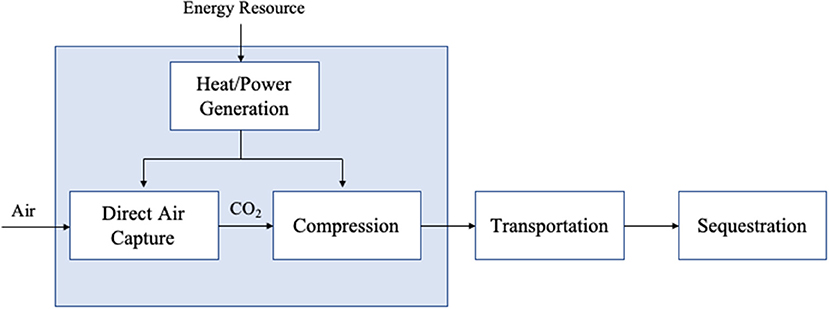
Figure 1. Boundary conditions for this analysis (blue box) where DAC is coupled to a dedicated energy resource to maximize CO2 removal impact. Additional unit operations outside the blue box represent further processing outside the scope of this analysis.
The baseline DAC system studied here removes 1 million metric tons of CO2 per year (MtCO2/yr) from the atmosphere. Running at 90% capacity, it requires ~240 to 300 megawatts (MW) of steady-state power, or 7.3 to 8.9 GJ/tCO2 captured (American Physical Society, 2011; Keith et al., 2018). Consequently, the energy source must emit very little CO2 to assure the CO2 emitted during capture is only a small fraction of the CO2 captured. By comparison, 300 MW of power produced at a new coal or natural gas plant will emit ~2.0 or 0.8 MtCO2/yr, respectively1, more than offsetting (coal) and nearly offsetting (natural gas) the CO2 captured. We consider two low-carbon energy sources: natural gas with CO2 capture and storage (CCS) and low-carbon electricity (in different forms).
The system we study uses liquid sorbents (solvents), which have been the subject of two detailed cost estimates. Solvent-based DAC systems require high-grade heat, ~900°C, for the calcination reaction to decompose calcium carbonate. Of the required power and energy, 80% is in the form of high-temperature thermal energy (largely for calcination) and 20% is electricity (largely for compressors, pumps, and fans) (National Academy of Sciences Engineering and Medicine, 2019). We investigate high-temperature heat provided both by combustion and by electric resistive heating (Table 1). Other capture systems, not studied here, use solid sorbents and thereby can use lower grade heat, ~100°C. This adds several options for alternative thermal energy sources, including solar thermal heat, geothermal heat, and the direct use of waste heat from a thermal power cycle. Similar analyses for solid sorbent-based DAC are underway elsewhere (National Academy of Sciences Engineering and Medicine, 2019; Lawrence Livermore National Laboratory, 2020; McQueen et al., 2020).
Case 1A, the baseline system for this analysis, is a solvent-based DAC system with the following major units and process steps:
• An air contactor where air is passed over a solvent containing a metal hydroxide (either KOH or NaOH) which reacts with the CO2 in the air forming a carbonate (either K2CO3 or Na2CO3) in solution.
• A precipitator where the carbonate in solution reacts with aqueous Ca(OH)2 to produce CaCO3, which is recovered, as a slurry or crystallized, and dehydrated before being fed into the calciner.
• A calciner which decomposes the CaCO3 at high temperature (about 900°C) into CaO and a concentrated CO2 stream which is then dehydrated and compressed for transport and subsequent sequestration or utilization.
• A slaker which rehydrates the CaO to regenerate the Ca(OH)2 for reuse in the precipitation of the carbonate.
The calciner is fired internally with natural gas and oxygen produced at an air separation unit (ASU). Here, oxygen must be provided approximately stoichiometrically for the natural gas combustion within the calciner. As a result, the CO2 leaving the calciner comes from both the natural gas combustion and the carbonate decomposition, and the combined gas streams are then pressurized to 150 bar. The calciner must be operated continuously to avoid the startup and shutdown time lags and costs associated with bringing it to and from its high temperature. As a result, the DAC facility is run at full capacity, aside from scheduled maintenance; we assume a 90% annual capacity factor.
Given the significant power requirements, it is germane to consider where future reductions in thermal and electric energy demands for Case 1A might come from (Caram et al., 2020). The energy systems are already well-optimized. Calcination, or the thermal decomposition of CaCO3 into CaO and CO2, is a complex, multiphase process which occurs when the system temperature exceeds the thermal decomposition temperature of CaCO3 (~825°C for equilibrium at one atmosphere CO2 pressure), typically operating at 900°C or higher. The additional temperature is required both to increase reaction rate and to ensure complete decomposition of the carbonate. Guidance can be obtained from the differences in enthalpies where the energy demand for the calciner must exceed the enthalpy of decomposition of CaCO3 at 900°C, (ΔH° = 170 kJ/mol), or about 4.0 GJ/tCO2 (Zeman, 2014). This thermodynamic minimum requires 130 MW of power to handle 2.9 Mt of CaCO3 per year. It is equal to roughly 60% of the Case 1A thermal energy requirement (200 to 250 MW). Nearly all of the heat of calcination is given back at the exothermic absorption step (ca. 60%) and the steam slaking step (ca. 36%). Heat generated at the contactor cannot be recovered, because it is diffuse, but exergy losses can and are reduced by heat recovery from the calciner to pre-heat the CaCO3 and the oxygen from the ASU. Further heat integration is possible but comes with technical risk and increased capital and operating costs.
An electrically driven calcium-looping cycle is not part of Case 1A, but it is considered extensively in this study. It is assumed to have the same thermal efficiency and capital cost as the natural-gas-fired calciner. While the capital cost assumption is likely to introduce some errors, the spread in calciner cost and energy use across the cases is likely to accommodate the potential differences.
The electric power demand for Case 1A is mainly for compression, fans, and the ASU. Typically, over 200 kWh/tO2 is required for an ASU that produces a 95% pure O2 stream, while state-of-the-art systems have been described down to 160 kWh/tO2 (Rodríguez et al., 2012). Less energy is required for lower purity O2 streams, but then the purity of the exiting CO2 stream is also reduced. At 95.6% purity, the post-condensation CO2 stream has a purity of 97.1% (Keith et al., 2018). Fan power is required to overcome the pressure drop experienced as ambient air travels through the contactor bed and depends on the configuration of the packing material. The CO2 capture fraction from air will depend on packing performance and increases with bed depth; thus, systems with very low electricity costs may be able to afford higher fan power requirements to achieve greater capture fractions through deeper bed depths. This effectively lowers the interfacial contactor surface area to achieve the same amount of capture, and may reduce the overall system capital. Ultimately, energy reductions do not exist in a vacuum, they must be carefully optimized against desired outcomes and overall system cost.
The baseline Case 1A system includes onsite electricity production. The onsite power plant, “NGCC-CCS,” is a combined-cycle natural gas turbine with associated capture of 90% of the CO2 in the flue gas and compression of the captured CO2 to 150 bar. It converts the energy in natural gas to electricity at roughly 50% efficiency. The heat demand at the calciner dominates; only about 30% of the natural gas is burned at the NGCC-CCS, and the thermal content of the resultant electricity is only 20% of the total useful energy released from natural gas burning.
A schematic diagram of Case 1A is outlined in Figure 2. Additional background regarding the solvent-based DAC process is found in the Supplementary Material Sections A Brief History of Solvent-Based Direct Air Capture (DAC) and The Cost of Direct Air Capture.
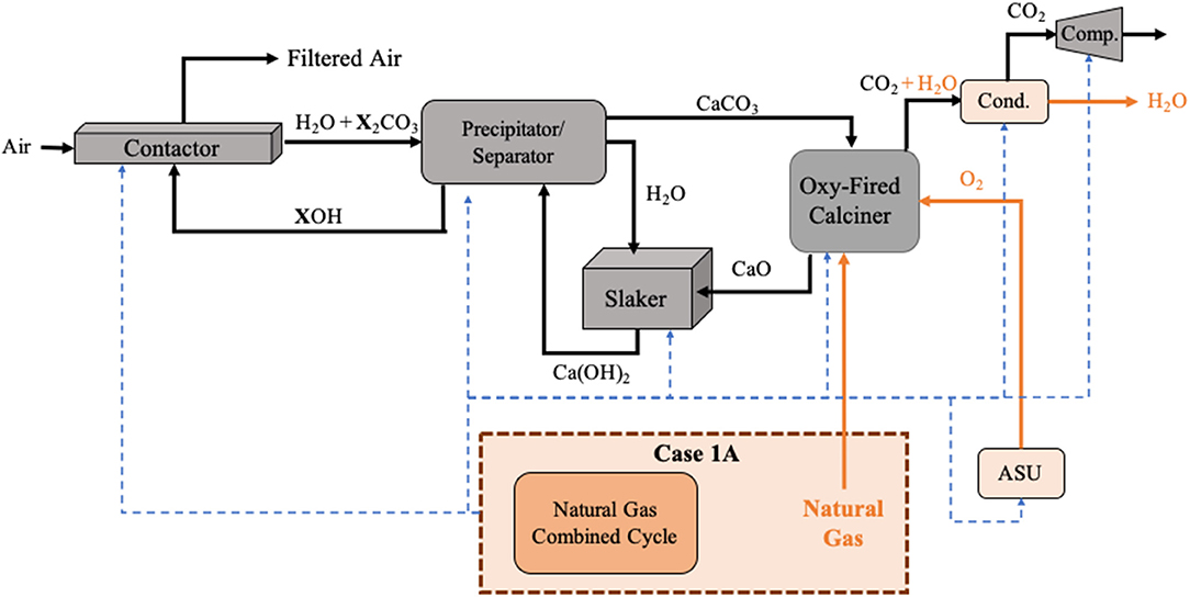
Figure 2. Schematic of DAC Case 1A where natural gas is internally combusted in the oxy-fired calciner, providing the thermal energy, and a natural gas combined cycle provides the electricity requirements for the system. The dashed blue arrows represent the flow of electricity within the system. The orange boxes and flows represent unit operations and species that are unique to Case 1A. X represented sodium (Na) or potassium (K) depending on the hydroxide used.
Our baseload capture system, Case 1A, includes variants that resemble two systems described previously: (1) the system presented in a 2011 report by the American Physical Society (2011) and follow-on modifications by Mazzotti et al. (2013) and Zeman (2014); and (2) the Carbon Engineering (CE) system developed by Holmes and Keith (2012), Keith et al. (2018). For this analysis we have harmonized both systems for consistency in the boundary conditions; in particular, the APS system used grid electricity, but here both systems produce electricity onsite. The design of the APS system was based on a more conventional approach similar to point-source carbon capture applications. It uses a series of squat towers with counter-current, vertical flows between air and solvent, while the design by Keith et al. aims to reduce cost through use of a cooling tower-like open-air system with cross-flow (horizontal flow of the air). These systems will be referred to as Vertical Flow (VF) and Horizontal Flow (HF), respectively. The major capital expenses are categorized in Table 2. The gross capture costs for the full VF and HF systems are $390 and $220, respectively, per ton of CO2 removed from the atmosphere. This $170/tCO2 cost difference is one measure of the uncertainty of our cost estimates. The assumed price of natural gas is $3.25/GJ ($3.43/MMBtu) throughout this paper (National Academy of Sciences Engineering and Medicine, 2019).
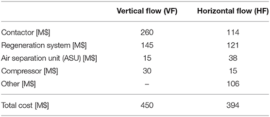
Table 2. Bare module costs of major equipment in the vertical flow (VF) and horizontal flow (HF) cases.
The capture costs of the VF and HF systems were compared previously (Keith et al., 2018). We expand here on two sources of the cost difference: the air contactor and the regeneration facility. In essence, the VF system uses a conservative design of high technological readiness, and the HF system integrates high technology readiness level components in a novel, bold approach. Regarding the contactor, the VF system has the configuration used by the chemical process industry, where a counter-flow of gas and liquid, in enclosed absorption columns featuring structured metal packing, controls and maintains process conditions, enhances mixing, and increases both reactivity and selectivity. The VF capture system requires vertical flow in 335 cylindrical absorbers, each 12 m in diameter and 2.8 m in height. The HF system has a more novel cross-flow design (Holmes and Keith, 2012; Keith et al., 2018) based on the partially enclosed design used in cooling towers. The liquid flows downward over high-surface-area PVC plastic packing, while air flows horizontally ~7 m through the contactor. Ten contactors, 20-m-tall by 200-m-wide, are required. The bare equipment cost for the VF air contactor is more than twice as high as for the HF system: $260 million vs. $114 million (Keith et al., 2018).
The two regeneration systems also differ. Both systems use an oxy-fired calciner, but the VF system uses a rotary calciner and the HF system uses a less expensive fluidized-bed calciner. The rotary calciner is similar to the calciners used in the pulp and paper industry as well as the lime and cement industries. The fluidized-bed calciner has been demonstrated at scale in the lime, cement, metals processing, and chemical industries, with the first industrial application of the multi-stage fluidized bed calciner in 1949 (Gupta and Sathiyamoorthy, 1998). However, the HF application is novel, which introduces uncertainty regarding attrition losses and extent of reaction (see Supplementary Material Section The Cost of Direct Air Capture). To create CaCO3 solids to feed into the calciner, the VF system uses a precipitator, and the HF system requires a more expensive pellet reactor to produce fluidizable material. The precipitator is ubiquitous in the pulp and paper industry, where it is commonly referred to as a causticizer. The pellet reactor used in the HF variant is an innovation borrowed from wastewater treatment, where the initially seeded CaCO3 needs to react slowly to form larger crystalline pellets as it resides in the reactor (Keith et al., 2018). The thermal energy requirements for pellet dewatering and pre-heating are minimized by heat integration. The bare capital cost for the VF regeneration system is only slightly higher than for the HF system: $145 vs. $121 million.
A key final economic factor is the Lang Factor (actual or notional), which is used to multiply the cost of major pieces of process equipment to arrive at a fully installed greenfield cost of the complex (Lang, 1947a,b; Lang, 1948). This full complex cost includes installation of main equipment and all supporting facilities and is meant to represent the total installed cost of the plant, including inside and outside battery limits (Dysert, 2003).
The VF variant, following the APS report, uses a Lang factor to multiply cost estimates for the bare pieces of major equipment to arrive at a full plant cost (American Physical Society, 2011). The VF variant uses a 4.5 factor. The APS report used Lang factors of 6.0 and 4.5: a 6.0 factor is appropriate for unproven technologies at the conceptual stage, and a 4.5 factor is appropriate for technologies that have been demonstrated but not commercially deployed. The HF variant builds on Keith et al., where a Lang factor is not used, but a proxy Lang Factor of 3.2 can be back-calculated (See Supporting Information for more details) (Keith et al., 2018).
The energy inputs for the VF variant of Case 1A are also considerably higher than for the HF variant. Per ton CO2 captured from air, the VF system requires 7.2 GJ thermal and 1.7 GJ electric, while the HF system requires 5.8 GJ thermal2 and 1.5 GJ electric. The two systems differ in the thermal efficiency of the process, including heat integration, and in the pressure drop as the air moves through the contactor. The VF variant uses a metallic packing material which has a pressure drop of approximately 100 Pa/m (280 Pa across the contactor), whereas the HF variant uses a plastic-based packing material that has a much lower pressure drop of 9.7 Pa/m (68 Pa total). We propagate both pairs of energy costs in this analysis, along with the significantly different capital costs.
Our interest in this paper is to compare natural gas and electricity as DAC energy sources. An intermediate case, Case 1B, is all-electric inside the DAC battery limits where electricity is generated by a natural gas fired power plant. Specifically, it features a much larger NGCC-CCS (roughly 270 MW instead of 50 MW) and an electric calciner with resistive heating rather than a thermal calciner fired by the oxy-combustion of natural gas internally. As a result, relative to Case 1A, less CO2 needs to be compressed at the calciner—only the CO2 removed from the air, because the CO2 produced at the NGCC-CCS is compressed there. Also, there is no ASU or condenser (as water is not produced at the calciner). This system is shown schematically in Figure 3, along with additional electricity generating cases that will be discussed later in this analysis.
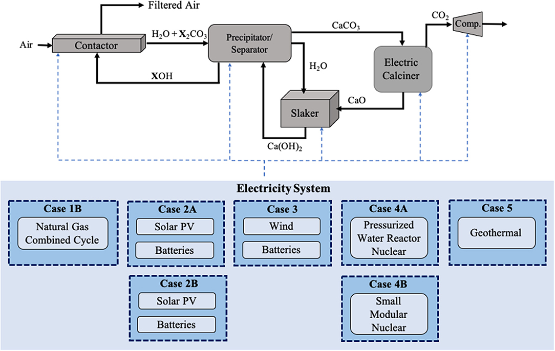
Figure 3. Schematic of DAC Case 1B through Case 5 where all energy requirements for the system are met using electricity through the use of an electric kiln. The dashed blue arrows represent the flow of electricity within the system. Here, X represented sodium (Na) or potassium (K) depending on the hydroxide used.
While an electricity-powered calciner is possible for both the fixed-bed calciner used in the VF variant and the fluidized-bed calciner used in the HF variant, the fluidized-bed calciner requires dedicated gas flow to fluidize the carbonate. Either recycled CO2 or steam could be used as the fluidizing medium. If CO2 is the fluidizing medium, the calciner energy requirements will be increased to achieve the same kinetics, because the carbonate decomposition to CaO and CO2 is endothermic and equilibrium-limited (Lin et al., 2011). Alternatively, using steam may complicate the recovery of the CaO.
Our approach to estimating the costs of the all-electric systems considered in this paper is to strip out all the costs associated with the energy system from both variants of Case 1A and then add back the costs of replacement energy systems. For Case 1B, we add back the cost of the large gas turbine and the purchased gas. We make the simplifying assumption that the electric and thermal calciners have the same capital and non-energy operating costs. The thermal energy requirements for Case 1B are the same as for Case 1A, but the electric loads are smaller because of the smaller compressor and the absence of the ASU. The electric loads are 1.2 and 1.0 GJ/t, respectively, for the VF and HF systems, down by 0.5 GJ/t. Two-thirds of the savings is due to the absence of the ASU and one-third to the smaller compressor. The overall natural gas input for Case 1B is nearly twice as large as for Case 1A, because of the roughly 50% efficiency of the NGCC-CCS.
The energy supply for all-electric DAC can come from non-fossil-fuel energy sources instead of natural gas. The DAC capture system exclusive of the energy system is identical to the one in Case 1B; in particular, there is an electric calciner. We explore six non-fossil systems that provide the required 300 MW (VF) and 240 MW (HF) of steady electric power. We restrict our analysis to dedicated power plants, which allow co-location and systems integration (not included in this analysis).
Table 1 lists these systems, which use four electricity sources: solar photovoltaics (two versions), wind, nuclear fission (two versions), and geothermal energy. We rely heavily on the 2020 annual EIA Cost and Performance Characteristics of New Generating Technologies for unit capacity, capital costs, fixed and variable operating and maintenance costs, and construction lead times (U.S. Energy Information Administration, 2020a). Capital and fixed costs are resized using power-law scale factors. The plant size is determined (a) by the electricity requirements for the DAC facility when the energy resource produces constant power, and (b) for wind and solar power, by the estimated available wind/solar resource, overproducing electricity during operational hours and providing sufficient utility-scale battery storage to assure continuous operation. We do not explore undersizing the solar and storage or wind and storage energy system and running the capture facility less than full time, which would decrease the contribution to the total capture cost contribution of the energy system but increase the contribution from the capture system. The complete EIA data set and adjusted capital costs for energy infrastructure is presented in the Table 3 and further described in Supplementary Table 9.
For solar PV we explore two designs, meeting the demand either on an average day of the year or on the day with the least sunlight (the winter solstice). Additionally, while high temperature solar thermal concentrators with high temperature storage may present another technically feasible alternative, we do not explore this option on account of both technical and economic uncertainty. For the nuclear case we investigate both a current large reactor complex coupled to multiple DAC units and a possible future small modular reactor. In all cases the assumed economic lifetime of the energy source and DAC complex is 20 years. Process diagrams for each energy alternative are provided in the Supporting Information.
The DAC system must be operated continuously and at a constant rate so as to accommodate the high-temperature calcination, which cannot be started and stopped quickly. Accordingly, when the electricity is produced by either the sun or the wind, storage must be provided. We account for some impacts of intermittency but not others. We scale the solar field and the wind turbine to produce enough daily energy to provide for flat daily demand for a representative day and use batteries to store and release energy during the day. In the two solar cases, Cases 2A and 2B, the solar collectors have single-axis tracking (as used in the EIA cost report). Case 2A is energy neutral over the year, because the field and batteries are sized to reflect an average day of the year, when the average PV power output is assumed to provide 35.2% of the nameplate PV capacity (NREL, 2019)—equivalent to 8.45 peak sun-equivalent-hours per day, which is representative of the average solar output of the most advantaged locations. Day-to-day storage and inter-annual variability are neglected.
In Case 2B, the system is sized to provide the needed daily power demand on the least sunny day (the winter solstice), when the average PV power output is assumed to provide 24.1% of the nameplate PV capacity (NREL, 2019)—(5.78 peak-sun equivalent hours) (Honsberg and Bowden, 2017). For Case 2B, electricity is exported on all the other days of the year, sold for $60/MWh.
The EIA solar data are for a 150 MW solar field costing $200 million, or $1,331/kW installed (U.S. Energy Information Administration, 2020a). Because the capacity factors for Case 2A and Case 2B are about one-third and one-quarter, respectively, and the required steady output is as much as 300 MW in both cases, ~900 MW and 1,200 MW of installed capacity are required, along with 4,800 and 5,400 MWh of battery storage (300 MW for 16 and 18 h), respectively. More accurately, Case 2A requires a 940 MW installation and a 750 MW installation, for the VF and HF variants, respectively, to produce the power required. Using a 0.95 scaling factor, the installed costs are reduced from $1331/kW to $1,215/kW (VF) and $1,228/kW (HF). For Case 2B, the required installed capacity is 1,400 MW (VF) and 1,100 MW (HF), and the installed costs are $1,191/kW (VF) and $1,204/kW (HF). The installed costs for the solar systems, exclusive of the batteries, are roughly $1,140 (VF) and $930 (HF) million for Case 2A, and $1,660 (VF) and $1,350 (HF) million for Case 2B without considering construction lead time.
Case 3 assumes a strong, steady wind with an average daily power output that is 52% of nameplate wind capacity, reflective of the most advantaged wind production locations (NREL, 2019). We do not account for daily variations in wind power. The EIA wind data are for a 200 MW onshore wind facility costing $260 million ($1,319/kW installed). The required wind capacity is 620 MW (VF) and 500 MW (HF), which carries a cost (again using a 0.95 factor) of $1,247/kW (VF) or $1,260/kW (HF) (U.S. Energy Information Administration, 2020a). The installed cost for the wind facility, exclusive of the batteries, is $770 (VF) and $630 (HF) million. Here, 4,000 MWh (VF) and 3,200 MWh (HF) of battery storage is required.
Following the EIA again, the reference utility-scale battery storage system has a storage capacity of 200 MWh (50 MW for 4 h), a 20-year economic life, an 85% round-trip efficiency and an installed cost of $346/kWh. Once more, a 0.95 factor is used for scaling based on the battery capacity (MWh), the unit battery cost per kWh for the HF case is $296/kWh, $294/kWh, and $301/kWh for Cases 2A, 2B, and 3, and the capital required for the batteries adds roughly $1,290, $1,500, and $970 million to the outlay for Cases 2A, 2B, and 3, respectively. The battery cost is 55, 50, and 57% of the total (wind field or solar field plus batteries), respectively, and the system cost including the batteries is $2,340, $3,030, and $1,700 million, respectively.
Sites for the solar field and the wind turbines are assumed to resemble the best available insolation and the best available wind. For Case 2A the site would be near the equator, which minimizes intra-annual variation. For Case 2B, the site is characteristic of the U.S. Southwest. For Case 3, the site has strong, steady winds.
When nuclear power is the low-carbon electricity source, we consider two alternatives. In Case 4A, a 2.2 GW nuclear power complex using pressurized water reactors (PWR) provides the electricity (U.S. Energy Information Administration, 2020a). The installed cost of the plant is $6,300/kW, or $13.6 billion. Since the nuclear power complex is far oversized for a single 1 MtCO2/yr capture system and does not economically scale down, we couple several DAC capture systems (in fact, seven for the VF system and nine for the HF system) to the complex, but we retain the $6,300/kW cost.
In Case 4B, a small modular reactor (SMR) scaled to a single DAC capture system provides the electricity (NuScale, 2019). SMRs have a lower technology readiness level than traditional pressurized water reactors and are not commercially available today. The capital cost for a particular SMR design proposed by NuScale is estimated to be $2.5 billion for a multiple-module 685 MW plant, or $3,600/kW (Black et al., 2019). Using a 0.7 scaling factor to scale-down the plant to 300 MW, the installed cost becomes $1.4 billion and the unit cost becomes $4,640/kW (VF) and $4,950/kW (HF). The NuScale SMR powering the all-electric DAC system has a capital cost that is roughly 75% of the EIA PWR system. The SMR fixed operating and maintenance costs are assumed to be proportional to the values for the large PWR from the EIA.
The cost and performance data for geothermal electricity generation3 are for the least expensive geothermal plant that could be built in the Great Basin region of the US, the system chosen in the EIA Annual Energy Outlook (U.S. Energy Information Administration, 2020a). The geothermal EIA plant has a base capacity of 50 MW and a cost of $134 million, or $2,680/kW. Using a 0.95 scaling factor, a 300 MW energy system has an installed capital cost of $730 million, or $2,450/kW.
The capacity factor is the ratio of the actual operating capacity of a given industrial facility divided by the maximum operating capacity of the facility over a defined period. In the present work, there are two important capacity factors: the annual average capacity factor and the daily capacity factor. A daily capacity factor has been applied for intermittent energy resources based on their availability during a daily cycle. Average annual capacity factors are applied to baseload systems that typically operate on a 24 h a day, 7 days a week basis, such as nuclear, geothermal, and natural gas power and the DAC plant itself. These continuously operated systems have on-line factors <100% due mostly to planned maintenance.
In the present analysis, we are coupling the power source to the DAC plant, such that planned downtime can be aligned. The base assumption is that the DAC plant has an average annual availability of 90%, a similar assumption as in Keith et al. (2018). As a result, for example, while a standalone nuclear power plant could have an annual average capacity factor of 97%, for the DAC complex both the nuclear plant and DAC plant would have an average annual capacity factor of 90% to align their operation. However, for intermittent energy sources such as wind and solar to couple to a DAC plant with 90% annual average capacity factor, energy storage is required. For all cases, it is assumed that 1 MtCO2 is captured per year when the DAC facility operates at a 90% annual capacity factor. Unplanned outages, including cloudy days for solar and still days for wind, have not been specifically incorporated into the analysis.
The cost of capital is usually determined by the return expectations of equity investors and the interest rates required by lenders for borrowed funds. These returns and interest rates are driven by the perceived risk, including technical, operational and financial factors. The higher the risk, the higher the interest rates and investor returns expected. The ratio of invested and borrowed capital can vary, and their fractions determine a weighted average cost of capital (WACC, in percent per year) for the project.
In this study an 8.5% WACC is assumed, as a compromise value that takes into account both the novelty of the technology and the likelihood of favorable public policy. Taking into account only the novelty of solvent-based DAC, the WACC would be similar to the rates seen for new technology in start-up companies, which often are 10% or greater. However, given the common-good nature of addressing climate change, public policy support—including tax-free financing and loan guarantees—might lead to a much lower WACC value, possibly approaching 5%. The 8.5% WACC, as seen by an average firm in the S&P 500, is used to convert overnight capital cost to a full cost that includes financing during the plant's construction time via a lead time factor. This lead time factor is applied to the overnight CAPEX to give a time zero construction cost. For example, a 3-year construction time (consistent with wind generation) corresponds to a lead time factor of 1.155, whereas a 6-year lead time (consistent with nuclear generation) increases the value to 1.33. The 8.5% WACC and 20-year economic lifetime are then used to determine a 10.57% annual capital recovery factor over the full 20-year economic life. All monetary values are reported in 2019 US dollars ($).
The cost of electricity at the back gate of a power plant can be estimated using the contributions of variable and fixed costs as well as a contribution from annual capital recovery. Annual capital recovery can be calculated by using the total invested capital, the WACC associated with the investment, and the expected lifetime of the power plant. While different types of power plants may have significantly different physical plant lives, in this analysis the LCOE calculation utilizes the assumed economic life of 20 years for each type of plant to simplify comparisons among them.
The gross capture costs for Case 1B are $490/tCO2 for the VF plant and $300/tCO2 for the HF plant. The roughly $100/tCO2 increment in the gross capture cost for Case 1B relative to Case 1A reflects the inefficiencies associated with producing electricity onsite for the calciner, as opposed to burning the natural gas directly within the calciner.
Figure 4 disaggregates the gross capture costs for the VF and HF variants for Cases 1A and 1B. The costs within the dashed lines are the common costs for Cases 1A and 1B for each of the variants; outside the dashed lines are the costs of the four natural-gas-based energy systems. The costs within the dashed lines are the costs carried forward to the non-fossil all-electric cases that we consider next.
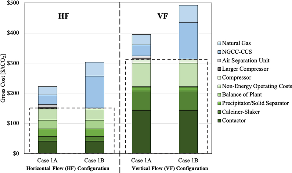
Figure 4. Major cost components for Cases 1A and 1B. For both the VF and HF variants, the dashed lines isolate the costs that are common for Cases 1A and 1B, i.e., the costs other than those for the energy systems. These isolated costs are also the costs for the two variants that are carried forward for all the low carbon all-electric cases.
Every system that removes CO2 from the atmosphere must use energy and materials to accomplish the job. Until such time as the entire economy does not add CO2 to the atmosphere, the flows of energy and materials accomplishing CO2 removal will create CO2 flows into the atmosphere that partially (or even entirely) negate what the system is intended to achieve. Moreover, DAC may be accompanied by flows into the atmosphere of methane (CH4) and other non-CO2 greenhouse gases. These emissions raise the “net” cost of CO2 removal from the atmosphere, relative to the gross cost. They have the potential to play a large role in the economic viability.
In the highly simplified analysis here, we restrict out attention to one source of CO2 emissions (CO2 not captured at the NGCC-CCS) and one source of CH4 (methane leakage upstream of the DAC facility). We define a parameter, x, which we call the takeback parameter, which measures the tons of CO2-equivalent (CO2e) emissions into the atmosphere per ton of CO2 removed from the atmosphere:
The Global Warming Potential (GWP) of methane is the ratio of the warming of the Earth per ton for emitted CH4 to the warming per ton of emitted CO2. The GWP depends on the time horizon over which the warming is integrated. An extra ton of CH4 added to the atmosphere warms the Earth much more than an extra ton than CO2. But CH4 has a much shorter lifespan in the atmosphere than CO2, roughly, a 12-year half-life for CH4, vs. a complex lifetime for CO2 where a substantial fraction remains for hundreds of years. Consequently, the longer the time horizon over which CH4 and CO2 are compared, the smaller the CH4 multiplier. The multipliers we choose are 86 for GWP20 (20-year time horizon) and 32 for GWP100 (100-year time horizon).
The cost of the gross amount of CO2 captured (gross cost) is analogous to the cost of the DAC system per ton of CO2 the system physically removes from the atmosphere. The cost of the net amount of CO2 captured (net cost) refers to the adjusted cost of CO2 capture, which includes emissions that occur as a result of the process; this provides the cost per ton of CO2 net removed from the atmosphere. The take-back parameter allows the determination of the net cost from the gross cost:
When x = 1, as much CO2 or equivalent flows into the atmosphere as is removed from the atmosphere, so the net cost of removal is infinite: money is spent, and nothing is achieved. For x > 1, Equation (2) is undefined.
The system boundary for the DAC system and its energy sources can be made arbitrarily large, thereby including ever more emissions, generally with ever less accuracy of the estimates. We choose to draw a system boundary here that includes only two kinds of emissions (1) the CO2 emissions associated with capturing <100% of the CO2 from the NGCC-CCS facility, and (2) the CH4 emissions associated with the upstream leakage of CH4 from natural gas supply. We do not include the CO2 emissions associated with building the DAC system and its various energy systems.
Other than geothermal energy4, incomplete capture of CO2 from the NGCC-CCS and upstream methane leakage have no direct analogies in the non-fossil electricity systems considered below. Accordingly, we do not include any emissions from the non-fossil-fuel systems, which is why we discuss net vs. gross costs here rather than later in the paper. For a detailed evaluation of additional systems emissions contributing to the takeback parameter, for all of the cases treated in this paper, see the Supporting Information.
Thus, for Cases 1A and 1B, the emissions to be inserted into Equation (1) are:
To simplify this analysis, we include no emissions here for the non-fossil cases, and therefore x = 0 and 1/(1–x) = 1. In the Supporting Information we explore additional contributions to the takeback parameter, applicable to both natural-gas-based, and all-electric energy systems.
For Case 1A, the CO2 emissions contribution to the takeback parameter is calculated as follows: Assuming a heat of combustion of 53.4 GJ per ton natural gas, Case 1A burns 0.16 and 0.20 tons of natural gas to capture 1 ton of CO2 for the HF and VF systems, respectively (including both thermal and electric requirements at a 48% conversion efficiency of natural gas to electricity). Burning 1 ton of natural gas produces 2.7 tCO2 (U.S. Energy Information Administration, 2020a). Therefore, 0.44 (HF) and 0.54 (VF) tons of CO2 are produced at the DAC plant for each ton CO2 removed from the atmosphere.
We assume that all of the CO2 produced at the calciner is captured, but only 90% of the CO2 produced at the NGCC-CCS. Furthermore, as mentioned earlier, only 30% of the overall natural gas usage is burned at the NGCC-CCS and the remaining 70% is combusted inside the calciner. Therefore 0.14 (HF) and 0.17 (VF) tons of CO2 are produced at the NGCC-CCS, and the 10% not captured there (the total CO2 release from the DAC) is 0.014 (HF) and 0.017 (VF) tons of CO2 released to the atmosphere per ton of CO2 removed from the atmosphere.
For Case 1B, where all of the natural gas is burned at a much larger NGCC-CCS, 0.26 (HF) and 0.33 (VF) of natural gas are burned at the DAC plant per ton of CO2 captured. The result is 0.73 (HF) and 0.90 (VF) tons of CO2 production at the NGCC-CCS, releasing 0.072 and 0.090 tons of CO2 to the atmosphere, for each ton of CO2 removed from the atmosphere.
There is nothing sacrosanct about 90% removal from an NGCC-CCS. Investments to increase the capture fraction will reduce the take-back parameter and the net cost of CO2 removal from the atmosphere.
As for the CH4 emissions contribution to the takeback parameter, as shown in Equation (4) it requires the multiplication of three numbers: the methane flow rate into the system, the fraction of methane leaked during production, and methane's global warming potential (GWP). The two GWPs that we use in this analysis, as well as the four methane flow rates for the HF and VF alternatives in Cases 1A and 1B, have been provided in the paragraphs immediately above. We treat the leakage rate as a parameter and examine three specific leakage rates: (1) 0.2%, which is an aspirational target articulated by the oil and gas industry; (2) 2.3%, which is a recent estimate for the U.S. (Alvarez et al., 2018); and (3) 3.7%, which is a still more recent estimate from an analysis only of the Permian Basin in West Texas (Zhang et al., 2020).
Table 4 shows the results of applying Equations (1) through (4) to derive the net cost of CO2 capture. There are 24 net costs: all four combinations of the VF and HF variants of Cases 1A and 1B, three leakage rates, and two GWPs. Figure 5 plots the eight curves that result when the leakage rate of CH4 is treated as a parameter.
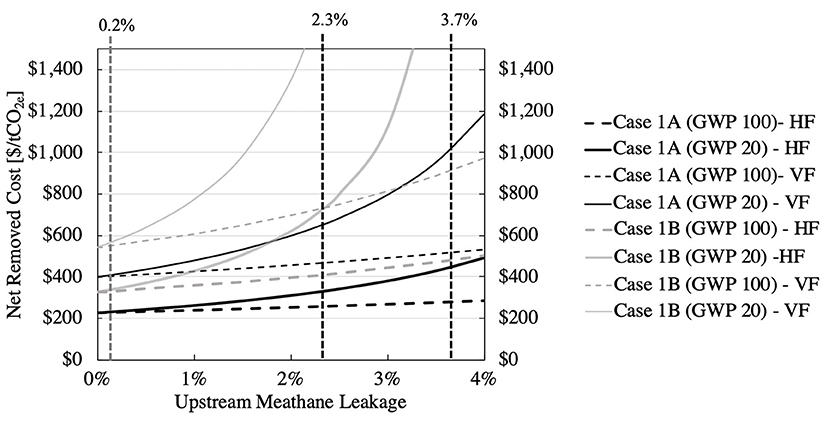
Figure 5. Sensitivity of the net removal cost to the upstream leakage percentage of methane. The three vertical lines correspond to the entries in Table 4 (see text).
In Table 4, let's work through one example: Case 1A for the HF variant, with 2.3% leakage5 and GWP20 (the 20-year time horizon). The CO2 contribution to the takeback parameter is 0.014. The CH4 contribution is the product of the methane delivered to the DAC (0.16 tons of CH4 per ton CO2), the upstream leakage rate, and the GWP (86), which is 0.31; note that it is 22 times larger than the CO2 contribution. The takeback parameter, from Equation (1), is the sum of the CO2 and CH4 contributions, 0.32. The net-cost to gross-cost ratio, from Equation (2), is 1.47. And, since the gross cost is $220/t CO2, the net cost is $323/t CO2, in agreement (when rounding errors are taken into account) with the $330/t CO2 entry in Table 4.
The combination of VF, Case 1B, 3.7% leakage rate, and 20-year GWP has a takeback parameter >1 and thus the net capture cost is undefined in Table 4. Eleven other entries have net costs above $500/tCO2. On the other hand, for 0.2% upstream leakage, the net cost of capture barely exceeds the gross cost. When, in the next section, we compare the entries in Table 4 to the capture costs for non-fossil DAC systems, it will become clear that the methane leakage rate can make or break the viability of the natural gas-powered DAC system.
In the Supporting Information we include additional contributions to the takeback parameter from both natural-gas-based and all-electric energy systems. These contributions are the CO2 emissions embodied in the DAC plant and the energy generating facility, as well as those associated with the methane supply chain. For the physical DAC plant, the embodied emissions distributed over the 20-year economic life of the power generation and DAC complex are generally <0.05 tons CO2 per ton of CO2 captured from air (tons per ton). Higher embodied emissions in the range of 0.10–0.18 tons per ton are found for solar PV plants with battery storage. Embodied emissions for plants constructed of traditional construction materials such as steel and concrete are small compared to complex components such as nuclear fuel, photovoltaic solar cells and lithium batteries (see Supplementary Material Section Direct and Embodied Emissions Analysis for Alternative Cases).
Figure 6 partitions the capture cost into DAC, energy, and storage components. The DAC component is the same for all VF cases and for all HF cases. For Cases 1A and 1B, the contribution to the capture cost from the natural gas equipment and the cost of the natural gas are separately identified. With thin narrow lines starting from the tops of the bars in Cases 1A and 1B, the six cost increments are shown (for the three leakage rates and two GWPs) that result in the net costs shown in Table 4.
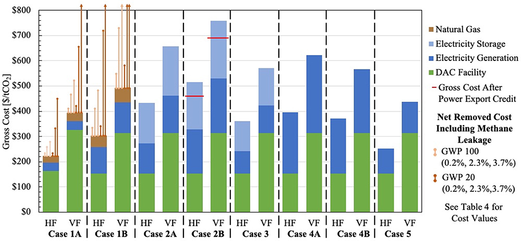
Figure 6. Disaggregation of capture costs into their principal contributions: DAC component, energy component and storage component. The narrow vertical lines for Cases 1A and 1B show the net costs in Table 4. Where these costs exceed $800/tCO2, the end is converted to an arrow and the lines are shown leaving the plot. The red, horizontal lines for Case 2B show the resulting net total cost after excess electricity is sold back to electricity suppliers.
The electricity generation costs and the non-energy costs are comparable for all seven all-electric cases. The storage costs are approximately the same as the generation costs for both the solar and the wind systems, and these costs are somewhat smaller for wind systems than for the solar systems. Shown by horizontal lines for Case 2B are the reduced costs when the sale of excess electricity through the year at $60/MWh is included.
Table 5 provides the gross capture costs shown in Figure 6. Table 5 also shows the supply requirements for natural gas, peak electricity, stored electricity, and the levelized cost of electricity. The all-electric Case 1B uses 1.6 times more natural gas than Case 1A, primarily because natural gas provides the electricity for the electric calciner directly in Case 1A but indirectly in Case 1B; however, the unit cost of the natural gas turbine in Case 1A is considerably higher, because of its small size. For nuclear and geothermal power, 300 MW (VF) and 240 MW (HF) of steady power are provided, and when solar and wind are the energy source, the installed (peak) capacity is much larger.
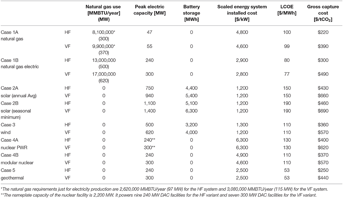
Table 5. Natural gas use, peak electricity, stored electricity capacity, LCOE, and gross capture cost.
The levelized cost of electricity (LCOE) includes capital cost recovery for both energy production and energy storage, as well as fixed and variable operating costs and is calculated over the economic lifetime of the energy generating facility. For Case 1A, the LCOE refers only to the electricity that powers the small (roughly 50 MW) NGCC-CCS system. For Case 4A, some cost savings are associated with co-constructing 7 or 9 DAC facilities, which could be estimated with a capital-scaling factor. Relative to the entries in Table 5, a 0.85 scaling factor decreases the cost of capture by $60/tCO2 for the VF case and $30/tCO2 for the HF case.
Figure 7 plots the total capture cost against the LCOE. Since the capture systems exclusive of the electric power systems are the same for the seven all-electric cases, and the same quantity of electricity is required, the points for these cases lie on a straight line. The y-intercepts correspond to the contributions to the total gross capture cost from the non-energy system, exclusive of the electric power plant and the storage. The values, $310/tCO2 and $150/tCO2 for the VF and HF systems, respectively, were developed above. The slope of the straight line is the electricity requirement, 2.3 MWh/tCO2 (8.4 GJ/ tCO2) for the VF configuration and 1.9 MWh/tCO2 (6.8 GJ/tCO2) for the HF configuration.
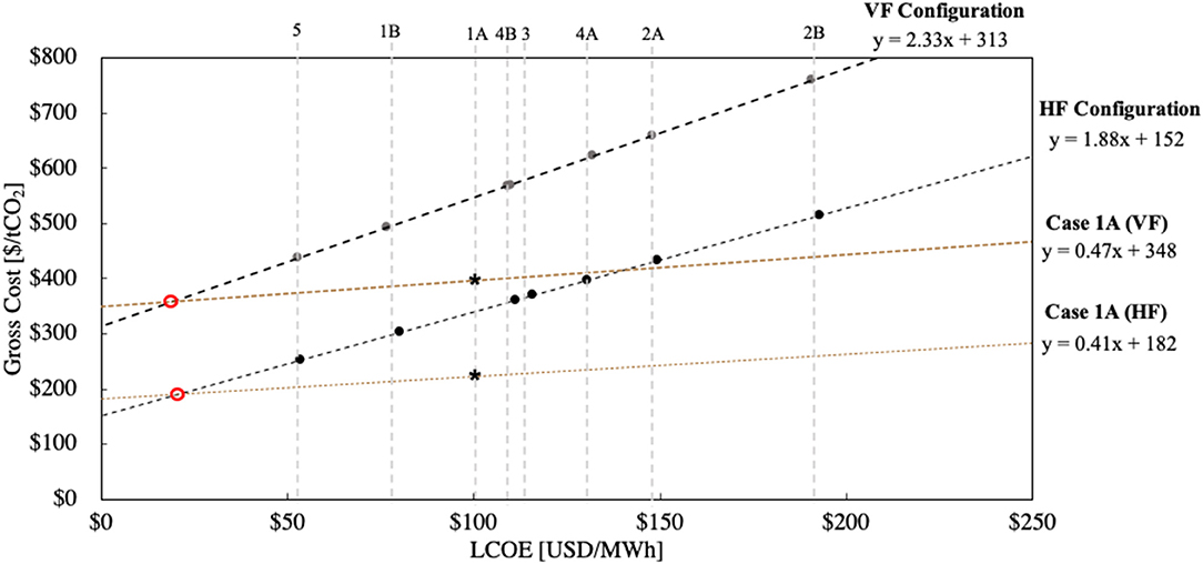
Figure 7. Gross cost of CO2 capture as a function of the levelized cost of electricity. The points for all cases other than Case 1A lie on a straight line, for the HF and VF variants separately. Case 1A is shown as a line, treating the cost of electricity produced at the small NGCC-CCS as a parameter. The points for Case 1A in this paper are shown as asterisks and the intersection of Case 1A and the all-electric alternatives as a red circle.
The two points for Case 1A lie below these lines, because the calciner requires natural gas, which is less expensive than electricity for the same thermal energy output. In addition to showing these two points, Figure 7 shows the lines that result when the LCOE of the electricity produced by the 50 MW NGCC-CCS is treated as a variable. The intersections show breakeven conditions, indicated as red circles on the figure: at an LCOE of about $20 per MWh for an all-electric system and for the NGCC-CCS in both variants of Case 1A, the common capture cost is about $350/tCO2 (VF) or $190/tCO2 (HF).
A perspective on the cost gap per ton of CO2 captured between using a ratable vs. intermittent power source for DAC can be illustrated by estimating how much the system cost could come down if the price of storage falls to $100/kWh—a third of the installed cost used in this analysis. For the HF DAC variant, the solar Case 2A (35.2% daily capacity factor), solar Case 2B (24.1% daily capacity factor) and wind Case 3 both demonstrate a roughly 20% decrease in the gross cost of DAC, resulting in costs of $340/tCO2, $350/tCO2, and $290/tCO2, respectively. Decreasing the cost of battery storage brings the cost of both solar cases to a level competitive with Case 4B (Nuclear SMR); the wind case becomes competitive with Case 1B (Natural Gas Electric).
A number of adjustable parameters that influence the cost of DAC are considered here. We illustrate the alternative options as “tune-able” knobs or switches in Figure 8. The three switches (two related to the contactor and one related to the regeneration facility) and the Lang-Factor dial display the key assumptions in our analysis that lead to the VF and HF capture systems that bracket our analysis. Arrows on the dials mark the specific values used in the calculations. Three dials have just one arrow, because a common value for this parameter is used for all cases. In the next section we perform sensitivity analyses on these three parameters.
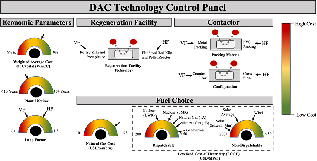
Figure 8. Direct air capture control panel, with three switches and six dials that summarize the options considered in this paper. The arrows on the dials show values used in the analysis of specific cases. For the three dials where there is just one arrow, the value is used for all cases and is examined in a sensitivity analysis.
Varying the economic parameters has a large impact on the capture cost of CO2. Here, a sensitivity analysis (Figure 9) provides insight into how the cost of alternative integrated DAC and energy systems vary with the assumed economic lifetime of the plant, weighted average cost of capital (WACC), and the price of natural gas. These variables were chosen as they are parameters that can vary widely from analysis to analysis, and over time and place. Comparing Figures 9A,B, the increases in the gross capture cost when the lifetime of capital is 10 years instead of 20 years and when the WACC is 12% instead of 8.5% are comparable for all cases.
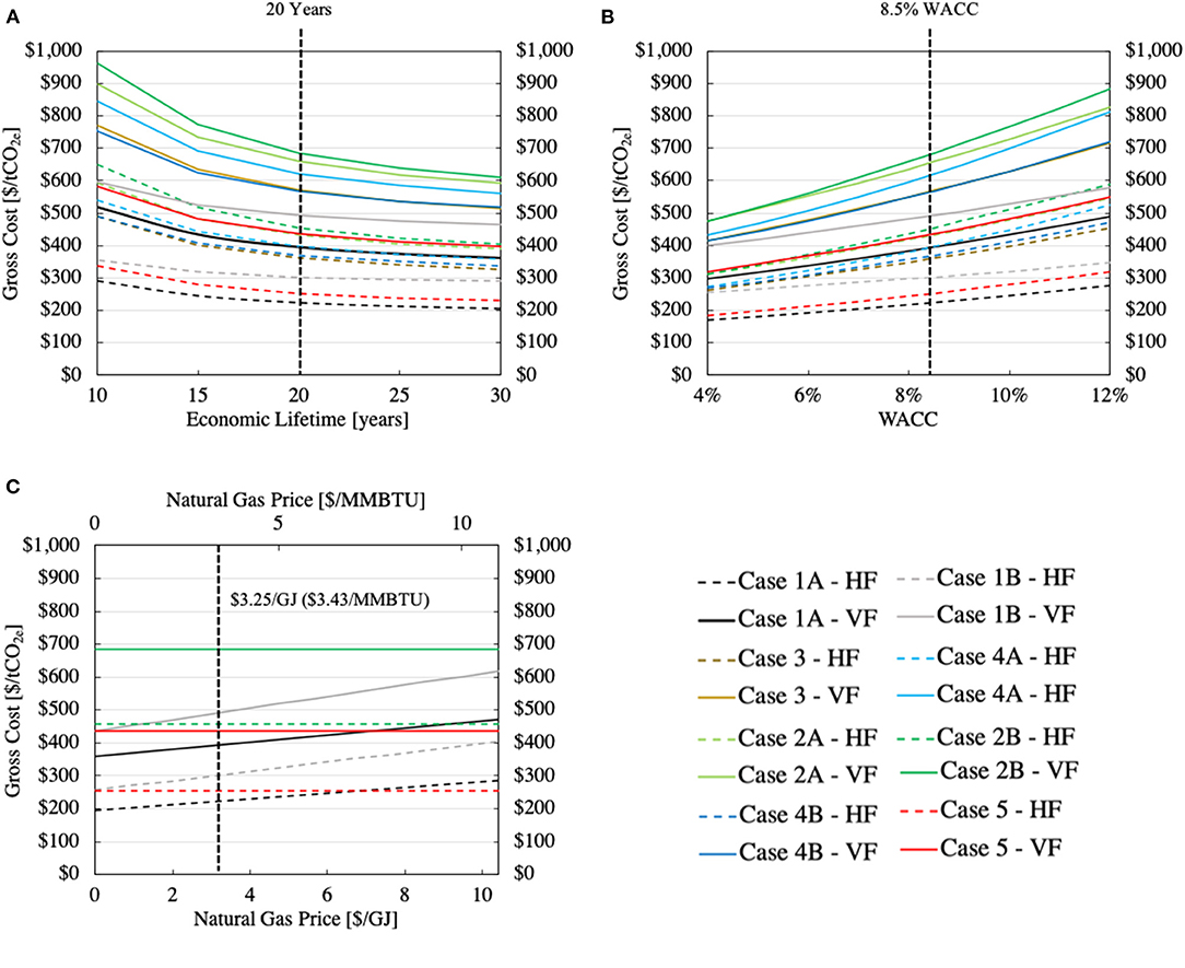
Figure 9. Sensitivity of the gross removed costs for all the considered alternative energy systems when just one parameter is varied: (A) the plant's economic lifetime (B) the weighted average capital cost (WACC) and (C) cost of natural gas. When a parameter is not varied it is fixed at 20 years for the economic lifetime, 8.5% for the WACC, and $3.25/GJ ($3.43/MMBtu) for the natural gas price. The vertical dotted black lines indicate these values when the parameter is varied. In (C), only two of the six non-fossil cases (2B and 5) are plotted to simplify the figure: all non-fossil options produce horizontal lines.
In Figure 9C, Case 1A, the gross capture cost for both the VF and HF alternatives is seen to increase about $10/tCO2 for each increase of $1/GJ ($1.05MMBtu) in the gas price; for Case 1B, the sensitivity is about twice as large, $20/tCO2 for the same increase in the gas price. A carbon tax has the same impact as an increase in the market price: a $100/tCO2 carbon price increases the price of natural gas by about $5/GJ ($5.3/MMBtu). To provide context for our reference natural gas price of $3.25/GJ ($3.43/MMBtu), note that the price in North America, roughly, fell from $5/MMBTU in 2014 to below $2/MMBTU at the beginning of 2020 (U.S. Energy Information Administration, 2019; CME Group, 2020). Prices globally have been converging, in part due to increased trade in liquified natural gas (LNG). European prices dropped from near $10/MMBTU in September 2018 to around $4/MMBTU in January 2020, and Asian natural gas prices fell from slightly above $10/MMBTU in 2019 to around $5/MMBTU in January of 2020 (U.S. Energy Information Administration, 2019, 2020b).
The costs developed here are for a First of a Kind (FOAK) plant. As a result of learnings from early build plants, the costs for Nth of a Kind (NOAK) plants should be significantly lower. It is also assumed that these DAC plants would be placed where operation is ideal. For example, a solar-powered DAC facility could be placed in a desert near the equator, where sunlight per day is nearly constant throughout the year. As these facilities are built and deployed, there may not be enough locations to sustain continued placement in optimum locations. We have also not taken into account inclement weather. Nor have we included any end-of-life salvage value for the process equipment.
The attractiveness of using any energy source with low CO2 emissions to power DAC depends on the level of decarbonization of the electricity system where it is to be deployed (the so-called “opportunity cost”). If a region is still building new power plants fuelled by coal and natural gas, using new low-carbon power to run DAC is likely to be less cost and climate impact effective than using that low-carbon power to make the new high-carbon plant unnecessary. Even if the region is no longer building new high-carbon plants but is still running its old ones, shutting down these old plants in favor of low-carbon energy sources is likely to be a better use of these low-carbon sources than powering DAC. Only when the region's electricity system is nearly completely decarbonized, do the opportunity costs of dedicating a low-carbon electricity source to DAC disappear.
An electric calciner could provide advantages over traditional calciner technology, as it can open up the system to low-carbon energy alternatives that can maximize net removal of CO2 from the atmosphere with solvent-based DAC. The creation and adoption of industrial-scale electric calcination technologies is required at scales not commercially available today. An effective electric calciner is critical to every all-electric variant of DAC. An extensive development effort is required to scale up the smaller electric calciners commercially available today.
Electrical heating can be achieved in many ways, including both directly and indirectly. Direct resistance heating can reach temperatures up to 2,000°C and is one of the simplest heating methods. Indirect heating, such as through indirect rotary calciner technologies, uses resistance heaters that are placed outside of the high-temperature shell and can reach temperatures up to 1,200°C (Sandalow et al., 2019). Both methodologies provide feasible routes to achieve the 900°C required by the solvent DAC process. There are multiple manufacturers of electric calciners; however, the size of the calciners to-date is limited to throughputs of hundreds of kilograms of calcium carbonate per hour (FEECO, 2016; Nortake Co, 2020), a scale much smaller than the roughly 300 tons per hour required for the solvent-based DAC process at 1 million tons of CO2 captured per year (Keith et al., 2018).
Ultimately, there are many different ways to analyze DAC technologies and many knobs that can be turned that lead to both high and low cost estimates. Therefore, it is increasingly important to create transparent and robust system boundaries and their corresponding cost estimates. Such estimates are needed to inform policy and help society arrive at realistic expectations.
The original contributions presented in the study are included in the article/Supplementary Material, further inquiries can be directed to the corresponding author/s.
NM, MJD, RHS, PP, and JW designed research and wrote the paper. NM and MJD performed the research and analyzed data. All authors contributed to the article and approved the submitted version.
The authors acknowledge ClimateWorks Foundation (a San Francisco based non-profit that has no ties to Climeworks) and the Hewlett Foundation for their financial support toward the completion of this study.
The authors declare that the research was conducted in the absence of any commercial or financial relationships that could be construed as a potential conflict of interest.
The Supplementary Material for this article can be found online at: https://www.frontiersin.org/articles/10.3389/fclim.2020.618644/full#supplementary-material
1. ^Estimates based on an ultra-supercritical coal fired power plant with a heat rate of 8800 BTU/kWh using coal which generates 206 lbs CO2/MMBTU (U.S. Energy Information Adminstration, 2013) and natural gas combined cycle power plant with a heat rate of 6,200 BTU/kWh using natural gas which generates 117 lbs CO2/MMBTU (U.S. Energy Information Administration, 2020a). Assumes a 90% annual on-line factor and no coupled carbon capture technology.
2. ^The system requires 13.4 t/hr natural gas to capture 112 tCO2/h from air with an additional 16 tCO2/h from post-combustion capture, corresponding to 0.10 tons of natural gas per ton CO2 captured. Using the higher heating value of methane (55.5 GJ/t), the energy requirements are 5.8 GJ/tCO2.
3. ^The geothermal energy system examined here may be more easily paired with sorbent-based DAC configurations; the relatively low temperature of the working fluid is high enough for the thermal recovery step of sorbent-based DAC (~100°C) (National Renewable Energy Laboratory, 2020), whereas, for the solvent-based all-electric systems, additional electricity-production infrastructure is required.
4. ^The emissions associated with geothermal production as reported by the EIA are 26 gCO2/kWh and are shown in the SI (see Supplementary Table 11). Including impact of these emissions increases the gross cost of capture by 5–6% for the geothermal cases.
5. ^Primary supply includes procurement to the larger distribution facilities where secondary distribution includes from the distribution facility to the individual user. Since a DAC facility will require large quantities of natural gas, we assume the facility is large and neglect emissions from secondary supply, resulting in roughly 4% decrease in methane leakage rate. Where the total methane leakage rate through primary and secondary supply is 2.3 %, the effective leakage rate is 2.2%.
Alvarez, R. A., Zavala-Araiza, D., Lyon, D. R., Allen, D. T., Barkley, Z. R., Brandt, A. R., et al. (2018). Assessment of methane emissions from the U.S. oil and gas supply chain. Science 361, 186–188. doi: 10.1126/science.aar7204
American Physical Society (2011). Direct Air Capture of CO2 with Chemicals. APS. Available online at: http://www.aps.org/policy/reports/popa-reports/loader.cfm?csModule=security/getfile&PageID=244407
Black, G. A., Aydogan, F., and Koerner, C. L. (2019). Economic viability of light water small modular nuclear reactors: general methodology and vendor data. Renew. Sustain. Energy Rev. 103, 248–258. doi: 10.1016/j.rser.2018.12.041
Caram, H. S., Gupta, R., Thomann, H., Ni, F., Weston, S. C., and Afeworki, M. (2020). A simple thermodynamic tool for assessing energy requirements for carbon capture using solid or liquid sorbents. Int. J. Greenh. Gas Control 97:102986. doi: 10.1016/j.ijggc.2020.102986
CME Group (2020). Henry Hub Natural Gas Futures Quotes. CME Group. Available online at: https://www.cmegroup.com/trading/energy/natural-gas/natural-gas.html (accessed March 9, 2020)
Creutzig, F., Breyer, C., Hilaire, J., Minx, J., Peters, G. P., and Socolow, R. (2019). The mutual dependence of negative emission technologies and energy systems. Energy Environ. Sci. 12, 1805–1817. doi: 10.1039/c8ee03682a
Dysert, L. R. (2003). Sharpen your cost estimation skills. Cost Eng. 45. Available online at: https://www.costengineering.eu/images/papers/Sharpen_Your_Cost_Estimating_Skills.pdf
FEECO (2016). Direct-Fired Rotary Kilns. FEECO. Available online at: https://feeco.com/rotary-kilns/ (accessed May 8, 2020).
Gupta, C., and Sathiyamoorthy, D. (1998). Fluid Bed Technology in Materials Processing. Boca Rotan, FL: CRC Press.
Holmes, G., and Keith, D. W. (2012). An air-liquid contactor for large-scale capture of CO2 from air. Philos. Trans. R. Soc. A Math. Phys. Eng. Sci. 370, 4380–4403. doi: 10.1098/rsta.2012.0137
Honsberg, C. B., and Bowden, S. G. (2017). Photovoltaics Education Website. Available at: www.pveducation.org.
Houses of Parliament (2018). Greenhouse Gas Removal. The Royal Society. Available online: https://royalsociety.org/~/media/policy/projects/greenhouse-gas-removal/royal-society-greenhouse-gas-removal-report-2018.pdf
Intergovernmental Panel on Climate Change (2018). Global Warming of 1.5°C. Intergovernmental Panel on Climate Change. Available online at: https://www.ipcc.ch/sr15/ (accessed August 26, 2019).
Keith, D. W., Holmes, G., St. Angelo, D., and Heidel, K. (2018). A process for capturing CO2 from the atmosphere. Joule 2, 1573–1594. doi: 10.1016/j.joule.2018.05.006
Lawrence Livermore National Laboratory (2020). Getting to Neutral: Options for Negative Emissions in California. Livermore, CA: Lawrence Livermore National Laboratory.
Lin, S., Kiga, T., Wang, Y., and Nakayama, K. (2011). Energy analysis of CaCO3 calcination with CO2 capture. Energy Procedia 4, 356–361. doi: 10.1016/j.egypro.2011.01.062
Mazzotti, M., Baciocchi, R., Desmond, M. J., Socolow, R. H., Tavoni, M., Socolow, R., et al. (2013). Direct air capture of CO2 with chemicals: optimization of a two-loop hydroxide carbonate system using a countercurrent air-liquid contactor. Clim. Change 118, 119–135. doi: 10.1007/s10584-012-0679-y
McQueen, N., Psarras, P., Pilorgé, H., Liguori, S., He, J., Yuan, M., et al. (2020). Cost analysis of direct air capture and sequestration coupled to low-carbon thermal energy in the U.S. Environ. Sci. Technol. 54, 7542–7551. doi: 10.1021/acs.est.0c00476
National Academy of Sciences Engineering and Medicine (2019). Negative Emissions Technologies and Reliable Sequestration. Washington, DC: National Academies Press.
National Renewable Energy Laboratory (2020). Geothermal Electricity Production Basics. National Renewable Energy Laboratory. Available online at: https://www.nrel.gov/research/re-geo-elec-production.html
Nortake Co (2020). Indirect-Heating Continuous Rotary Kiln. Nortake Co. Available online at: https://www.noritake.co.jp/eng/products/eeg/parts/detail/145/ (accessed May 8, 2020).
NREL (2019). Annual Technology Baseline Report: Electricity. NREL. Available online at: https://atb.nrel.gov/electricity/2019/index.html?t=cg.
NuScale (2019). A Cost Competitive Nuclear Option for Multiple Applications. NuScale. Available online at: https://www.nuscalepower.com/benefits/cost-competitive (accessed October 24, 2019).
Rodríguez, N., Murillo, R., and Abanades, J. C. (2012). CO2 capture from cement plants using oxyfired precalcination and/or calcium looping. Environ. Sci. Technol. 46, 2460–2466. doi: 10.1021/es2030593
Sandalow, D., Friedmann, J., Aines, R., McCormick, C., McCoy, S., and Stolaroff, J. (2019). ICEF Industrial Heat Decarbonization Roadmap. Tokyo: CDR Law.
U.S. Energy Information Administration (2019). Gas 2019. U.S. Energy Information Administration. Available online at: https://www.iea.org/reports/market-report-series-gas-2019
U.S. Energy Information Administration (2020a). Cost and Performance Characteristics of New Generating Technologies. Annual Energy Outlook 2020. U.S. Energy Information Administration. Available online at: https://www.eia.gov/outlooks/aeo/assumptions/pdf/table_8.2.pdf (accessed December 3, 2020).
U.S. Energy Information Administration (2020b). Short-Term Energy Outlook. U.S. Energy Information Administration. Available online at: https://www.eia.gov/outlooks/steo/marketreview/natgas.php
U.S. Energy Information Adminstration (2013). Capital Cost Estimates for Utility Scale Electricity Generating Plants. U.S. Energy Information Administration. Available online at: www.eia.gov (accessed February 16, 2020).
Zeman, F. (2014). Reducing the cost of ca-based direct air capture of CO2. Environ. Sci. Technol. 48, 11730–11735. doi: 10.1021/es502887y
Keywords: direct air capture (DAC), negative emissions technologies (NETs), carbon capture, carbon dioxide removal (CDR), energy resources, technoeconomic analysis (TEA)
Citation: McQueen N, Desmond MJ, Socolow RH, Psarras P and Wilcox J (2021) Natural Gas vs. Electricity for Solvent-Based Direct Air Capture. Front. Clim. 2:618644. doi: 10.3389/fclim.2020.618644
Received: 17 October 2020; Accepted: 30 December 2020;
Published: 27 January 2021.
Edited by:
Daniel L. Sanchez, University of California, Berkeley, United StatesReviewed by:
Stefano Stendardo, Italian National Agency for New Technologies, Energy and Sustainable Economic Development (ENEA), ItalyCopyright © 2021 McQueen, Desmond, Socolow, Psarras and Wilcox. This is an open-access article distributed under the terms of the Creative Commons Attribution License (CC BY). The use, distribution or reproduction in other forums is permitted, provided the original author(s) and the copyright owner(s) are credited and that the original publication in this journal is cited, in accordance with accepted academic practice. No use, distribution or reproduction is permitted which does not comply with these terms.
*Correspondence: Jennifer Wilcox, amx3aWxjb3hAc2Vhcy51cGVubi5lZHU=; orcid.org/0000-0001-8725-2558
Disclaimer: All claims expressed in this article are solely those of the authors and do not necessarily represent those of their affiliated organizations, or those of the publisher, the editors and the reviewers. Any product that may be evaluated in this article or claim that may be made by its manufacturer is not guaranteed or endorsed by the publisher.
Research integrity at Frontiers

Learn more about the work of our research integrity team to safeguard the quality of each article we publish.