 Tae-Yong An1†
 Subramani Surendran1†Sebastian Cyril Jesudass2
 Hyunjung Lee1
 Dae Jun Moon1
 Jung Kyu Kim3*
 Uk Sim1,4,5*
- 1Hydrogen Energy Technology Laboratory, Korea Institute of Energy Technology (KENTECH), Naju, Republic of Korea
- 2Department of Science and Engineering, Chonnam National University, Gwangju, Republic of Korea
- 3School of Chemical Engineering, Sungkyunkwan University, Suwon, Republic of Korea
- 4Research Institute, NEEL Sciences, INC, Jeollanamdo, Republic of Korea
- 5Center for Energy Storage System, Chonnam National University, Gwangju, Republic of Korea
Hydrogen has become an indispensable aspect of sustainable energy resources due to depleting fossil fuels and increasing pollution. Since hydrogen storage and transport is a major hindrance to expanding its applicability, green ammonia produced by electrochemical method is sourced as an efficient hydrogen carrier. Several heterostructured electrocatalysts are designed to achieve significantly higher electrocatalytic nitrogen reduction (NRR) activity for electrochemical ammonia production. In this study, we controlled the nitrogen reduction performances of Mo2C-Mo2N heterostructure electrocatalyst prepared by a simple one pot synthesis method. The prepared Mo2C-Mo2N0.92 heterostructure nanocomposites show clear phase formation for Mo2C and Mo2N0.92, respectively. The prepared Mo2C-Mo2N0.92 electrocatalysts deliver a maximum ammonia yield of about 9.6 μg h-1 cm-2 and a Faradaic efficiency (FE) of about 10.15%. The study reveals the improved nitrogen reduction performances of Mo2C-Mo2N0.92 electrocatalysts due to the combined activity of the Mo2C and Mo2N0.92 phases. In addition, the ammonia production from Mo2C-Mo2N0.92 electrocatalysts is intended by the associative nitrogen reduction mechanism on Mo2C phase and by Mars-van-Krevelen mechanism on Mo2N0.92 phase, respectively. This study suggests the importance of precisely tuning the electrocatalyst by heterostructure strategy to substantially achieve higher nitrogen reduction electrocatalytic activity.
1 Introduction
The modern technical society holds a shear desire for cost-effective, eco-friendly, and reliable energy technologies to mitigate pollution and ensure energy sustainability (Fiksel et al., 2014). Researchers and technologists have conceded with the development of hydrogen energy which was abundantly available and displayed potential applications in various sectors (Yue et al., 2021). However, the storage and transport of valuable fuel became an exceptional threat which involved complex storage facilities and cryogenic systems (Zhou et al., 2005). Ammonia was then ascertained as the effective hydrogen carrier, which can hold up to 17.65% of its total mass (Avery et al., 1988; MacFarlane et al., 2020). Ammonia can be transported over long distances under ambient conditions and could also be utilized as fuels directly (Zhao et al., 2019). Nevertheless, ammonia is produced by the high energy-consuming Haber-Bosch (HB) process, which involves nitrogen and natural gas (CH4), resulting in greenhouse gas (GHG) evolution (Kandemir et al., 2013; Safari et al., 2019). Technologies for eco-friendly and sustainable ammonia production are yearned to achieve supremacy over green energy.
Electrochemical nitrogen reduction reaction (NRR) is the most viable and simple technology developed for ammonia production. NRR involves water, N2, and renewable electricity to generate ammonia over six proton-coupled electron transfer (PCET) steps (MacFarlane et al., 2020). NRR is facilitated over an electrocatalyst which must exhibit better activity, selectivity, and stability over NRR electrolysis (Cui et al., 2018). Since the triple bond of dinitrogen (N≡N) has a high dissociation energy of nearly 941 kJ mol-1, NRR requires large overpotentials, which are much lower than required for hydrogen evolution reaction (HER) (Ren et al., 2021). Hence, HER becomes an active competitor for NRR, resulting in a lower ammonia yield rate and Faradaic efficiency (FE). Various electrocatalyst designs were engineered to increase activity for NRR and selectivity towards ammonia without the intermediate formation and HER (Du et al., 2021).
Mo-based electrocatalysts have been analyzed as the effective NRR electrocatalyst due to their higher affinity for nitrogen, as observed from the nitrogenase enzymes with Fe-Mo cofactors (Liu et al., 2020; Arif et al., 2023). The nitrogenase enzymes exhibit dominant HER, which makes them unfavorable for efficient ammonia production (Hinnemann and Nørskov, 2006). Several strategies were followed to design Mo-based electrocatalysts to achieve effective NRR performances (Guo et al., 2021). As an important design strategy, MoS2 was synthesized as an NRR electrocatalyst which exhibits a sufficient ammonia yield but poor FE due to dominant HER (Zhang et al., 2018a). Therefore, Mo-based electrocatalysts must be engineered to achieve a higher ammonia yield and effectively suppress HER. In this way, Yesudoss et al. (Yesudoss et al., 2021) synthesized the γ-Mo2N supported on h-BN sheets as an effective NRR electrocatalyst. γ-Mo2N/BN hybrids, with strong interactions and bridging bonds between Mo2N and BN, exhibit a superior NRR performance. Therefore, precise tuning of the electrocatalyst design can enhance the NRR activity with a high ammonia yield rate and FE.
Typically, Mo2C electrocatalyst exhibits a Pt-like behavior, metallic nature, and better stability (Huo et al., 2016; Su et al., 2019). Thereby, Mo2C nanodots embedded in carbon nanosheets (Mo2C/C) were analyzed as an electrocatalyst for NRR, which initially revealed better ammonia yield even under strong hydrogen spillover (Cheng et al., 2018). This is attributed to the higher density of active sites in the Mo2C/C electrocatalyst, which exhibited a low FE due to higher selectivity for HER. Henceforth, these electrocatalysts are engineered with Mo single-atom catalysts (MoSAs-Mo2C) (Ma et al., 2020), MoO2 quantum dots (Mo2C-MoO2) (Wan et al., 2022), and as Mo2C nanorods (Ren et al., 2019), which reveal significantly high NRR performances. Notably, MoS2/Mo2C heterostructures were designed recently, which exhibited a high NRR FE of about 42% due to the selectivity of the Mo atoms towards N2 adsorption (Ye et al., 2023). However, a low ammonia yield rate of nearly 1.41 μg h-1 cm-2 was observed. Besides, Mo2N was identified as an effective electrocatalyst due to its high conductivity and ample active sites for redox reactions (Hargreaves, 2013; Mtukula et al., 2017). Therefore, Mo2N was studied as an NRR electrocatalyst, which exhibited a high ammonia yield five times more than the prepared MoO2 electrocatalyst indicating the supreme activity of the N atoms in Mo lattice (Ren et al., 2018). Besides, Mo2N electrocatalyst exhibited significant selectivity towards ammonia indicating the reliability of the Mo2N electrocatalyst (Ren et al., 2018; Yesudoss et al., 2021). Even though, the Mo2C and Mo2N electrocatalysts exhibit considerable electrocatalytic NRR performances, the electrocatalysts actively performs HER resulting in decreased NRR efficiency. Therefore, the electrocatalysts must be engineered carefully to achieve higher NRR activity.
Consequently, tailoring the electrocatalysts through a heterostructure strategy can be adopted, which increases the electrocatalytic activity by synergizing the performances of two different structures (Su et al., 2019; Wan et al., 2022). Heterostructures provide structural and electronic modifications in the electrocatalysts by which tunable performances are achieved, which proliferate the electrocatalytic performances (Yuan et al., 2022). For instance, Chen et al. (Chen et al., 2022) modified the MoS2 electrocatalyst with in situ generated MoO2 and ZnO (MMZ) as heterostructures, revealing significantly better NRR performances. The MMZ electrocatalyst exhibited a five-fold increase in ammonia yield and FE compared to pristine MoS2, which indicates the multiplied electrocatalytic activity of the MMZ heterostructures. Therefore, the heterostructure formation has been a promising strategy in tailoring the performances of the pristine moieties to achieve considerably higher NRR performances. Besides, Co3O4-Mo2N heterostructures have revealed a high electrocatalytic activity due to the interfacial electronic effects between the two structures (Wang et al., 2022). The differential electron density between Mo2N and Co3O4 phases has improved the electrocatalytic activity of the heterostructures. Several other reports have suggested improved electrocatalytic activity by choice of suitable nitride heterostructures as an efficient strategy for NRR electrocatalysts (Yesudoss et al., 2021; Chu et al., 2022). Hence, the Mo-based electrocatalysts can be tailored with appropriate elements to achieve significantly higher ammonia yield rate and efficiency.
The above studies have motivated the fabrication of the single-phase transition metal carbides and nitrides into a heterostructure as an effective NRR electrocatalyst. In the present work, we demonstrate the preparation of the Mo2C-Mo2N0.92 nanocomposites and the analysis of NRR performances of the prepared electrocatalysts. Mo2C-Mo2N0.92 nanocomposites reveal the heterostructure formation of Mo2C and Mo2N structures. The prepared Mo2C-Mo2N0.92 electrocatalyst achieves a high ammonia yield rate of about 9.6 μg h-1 cm-2 and FE of nearly 10.15%, respectively. The enhanced NRR performances can be ascribed due to the synergistic activity of the heterostructures of Mo2C and Mo2N0.92, respectively. Hence, this study suggests promising electrocatalytic performances of the heterostructured electrocatalyst by tuning the structural and electronic properties of the single moieties.
2 Experimental methods
2.1 Synthesis procedure of Mo2C-Mo2N
Typically, a stoichiometric ratio of the precursors, molybdenum chloride (MoCl5) and urea (CO(NH2)2) were mixed together with 10 ml ethanol and aged on a hot plate at 80°C for 2–3 h. The as-prepared samples were further pyrolyzed at 800°C for 3 h under N2 flow. Further, the samples were prepared by varying the urea-metal ratio to 2:1 and 3:1, termed Mo2C-Mo2N0.92 and Mo2N0.92-Mo2C, respectively.
2.2 Characterizations
The crystal structure and phase formation of the samples were examined by powder X-ray diffraction (XRD; Rint 1000, Rigaku, Japan) with Cu Kα radiation (λ = 1.5418 Å). X-ray photoelectron spectroscopy (XPS; K-ALPHA+, Thermo Scientific) was used to determine the oxidation states of the elements in the electrocatalyst. The morphology and microstructure of the electrocatalyst was investigated by scanning electron microscopy (SEM; JSM-7500F, JEOL, Japan) and transmission electron microscopy (TEM; JEM-2100F, JEOL, Japan), respectively.
The slurry prepared using PVDF, carbon black and prepared electrocatalysts in the ratio 1:1:8 was loaded on carbon cloth (1 × 1 cm2) and dried in vacuum oven for further electrochemical studies. The electrochemical NRR studies were carried out in a three-electrode cell configuration using the VMP3-Biologic multi-channel potentiostat under 0.1 M KOH electrolyte with and without N2 purging. Graphite rod and Hg/HgO were used as the counter and reference electrodes, respectively. The Hg/HgO potential (E(Hg/HgO)) was converted into reversible hydrogen electrode (RHE) potential (ERHE) using Equation 1.
2.3 Quantitative evaluation of NRR
The ammonia content in the electrolyte after the chronoamperometry (CA) tests for 2 h at various applied potentials were measured using the colorimetric method. 5 ml of the collected electrolyte after CA tests was sampled with colouring agents and catalysts using the standard ammonia test kits. Then the intensity of the coloured solution was measured using the UV-vis spectrophotometer. The intensity of the respective UV curves at 680 nm were compared to the standard calibration graphs of ammonia to estimate the concentration of ammonia present in the solution. The calibration graphs were derived from UV curves prepared by various known concentration of standard NH4Cl salt. The linear curves from the UV plots yield the calibration graphs for ammonia. Hence, the concentration of ammonia can be estimated from the UV curves for samples after CA tests and calibration graphs (Liu et al., 2020).
The ammonia yield rate and Faradaic efficiency (FE) of the prepared electrocatalysts can be estimated using Equation 2 and Equation 3, respectively (Liu et al., 2020).
where, [NH3] represent the concentration (μg/ml) of the ammonia present in the corresponding electrolyte, V is the volume of the electrolyte (ml), t is the time of electrolysis (hours), A is the area of the electrode (cm-2), F is the Faradaic constant (96485 C mol-1), and j is the current density at CA tests (mA cm-2), respectively.
3 Results and discussion
3.1 Structural and morphological analysis
Mo2C-Mo2N0.92 is synthesized by the simple urea glass route (Figure 1A). Initially, the MoCl5 precursors are mixed with alcohols which primarily forms Mo-ethoxide (Mo(OC2H5)5) and the Cl¯ ions are released as HCl (Giordano et al., 2008). Further, mixing urea (CO(NH2)2) with the above solution replaces the ethoxide groups in Mo(OC2H5)5 due to the high solubility of urea under the presence of metal ions (Equation 4). Urea is used as both C and N precursors for the formation of Mo2C and Mo2N, respectively. The C=O bond cleavage in urea replaces the ethoxide molecule in Mo(OC2H5)5, and the urea moiety coordinates with the Mo5+ atom forming metal-urea complexes, Mo-(OCN2H4)5 (Equation 5). (Sardar et al., 2005) After heat treatment, the metal-urea complex is reduced into the desired Mo2N-Mo2C nanocomposites (Equation 6). By varying the urea-to-metal ratio (R), dominant phases of Mo2N and Mo2C can be achieved, respectively. Thereby, a lower urea content in the urea-metal ratio results in the dominant phases of Mo2C, and high urea content favors Mo2N formation respectively.
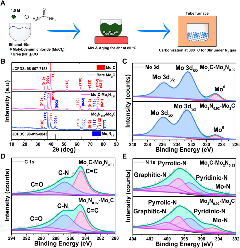
FIGURE 1. (A) Schematic representation of the synthesis procedure for Mo2C-Mo2N nanocomposites. (B) XRD patterns for the prepared Mo2C-Mo2N0.92, Mo2N0.92-Mo2C and bare Mo2C samples, respectively. XPS spectra of (C) Mo 3d, (D) C 1s, and (E) N 1s for the prepared Mo2C-Mo2N0.92 and Mo2N0.92-Mo2C samples.
The proposed reaction mechanisms are elucidated as follows.
The structural analysis of the prepared samples was evaluated by X-ray diffraction (XRD) analysis. XRD patterns obtained for Mo2C-Mo2N0.92 and Mo2N0.92-Mo2C display crystalline peaks for the prepared samples (Figure 1B). The obtained peaks are well-matched to the respective phases of Mo2C (JCPDS: 98–007–7158) and Mo2N0.92 (JCPDS: 98–015–8843). Similarly, XRD patterns for the bare Mo2C samples reveal the respective well-matched phases. The simultaneous existence of the XRD patterns of the two phases without any peak shift or peak broadening can ascribe to the heterostructure formation. XRD patterns for Mo2C-Mo2N0.92 prepared with 2:1 ratio reveals the dominant phases of Mo2C with relatively smaller presence of Mo2N0.92 phases. Similarly, XRD patterns for Mo2N0.92-Mo2C prepared with 3:1 urea to metal ratio displays the presence of dominant Mo2N0.92 phases with feeble Mo2C phases, respectively. Thereby, a low urea content favors Mo2C formation and a high urea content forms Mo2N0.92, respectively. Hence, Mo2N0.92 and Mo2C phases exist together in a single system exhibiting differences in relative intensity of the XRD patterns without any peak shift or peak broadening. The relative intensity of the XRD patterns for the samples prepared at different urea to metal ratio explain the dominant phases of the Mo2C and Mo2N0.92 moieties in the prepared electrocatalysts. Thus, the urea-metal ratio is the phase-determining factor for Mo2N and Mo2C.
The chemical states of the prepared Mo2C-Mo2N0.92 and Mo2N0.92-Mo2C samples were evaluated by the X-ray photoelectron spectroscopy (XPS) analysis. The Mo 3d spectra in Figure 1C can be deconvoluted into two peaks at 232.8 eV and 236 eV for Mo 3d5/2 and Mo 3d3/2, respectively. The small peak arising at the lower binding energy around 228.8 eV corresponds to the metallic Mo species for both Mo2C-Mo2N0.92 and Mo2N0.92-Mo2C samples. The C 1s spectra in Figure 1D display three deconvoluted peaks at 284.6 eV, 286.8 eV, and 289 eV corresponding to the sp-carbon (C=C) bonds (Yue et al., 2021), N doped carbon (C-N), and feeble C=O signals due to incomplete decomposition of urea (CO(NH2)2), respectively. The deconvoluted N 1s spectra in Figure 1E display major peaks at 397.4 eV, 398.7 eV, and 400 eV, corresponding to pyridinic-N, pyrrolic-N, and graphitic-N, respectively. Besides, the feeble peak around 394.8 eV suggests the presence of Mo-N bonds in the prepared samples (Zhang et al., 2022). Evidently, the Mo2N0.95-Mo2C samples reveal relatively higher intensity for Mo-N bonds compared to Mo2C-Mo2N0.92, which validates the dominant presence of Mo2N0.92 in the prepared sample.
The morphological and microstructure studies were observed using scanning electron microscopy (SEM) and high-resolution transmission electron microscopy (HRTEM) analyses. SEM images for the prepared Mo2C-Mo2N0.92 samples reveal the uniform distributions of the nanocomposites anchored to a substrate. SEM images of Mo2C-Mo2N0.92 sample reveal the average sizes of the nanocomposites around ∼50 nm (Figure 2A). HRTEM analysis reveals the lattice spacing of about 0.26 nm for Mo2C-Mo2N0.92 nanocomposites corresponding to (010) lattice planes of Mo2C (Figure 2B). The inset of Figure 2B shows the FFT patterns for the Mo2C-Mo2N0.92 sample, which reveal the crystalline phases of Mo2C. Similarly, the SEM images in Figure 2C reveal the average sizes of the nanocomposites around ∼110 nm for Mo2N0.92-Mo2C. The HRTEM analysis for Mo2N0.92-Mo2C sample reveals the lattice spacing of about 0.23 nm corresponding to (101) lattice planes of Mo2C (Figure 2D). Furthermore, the intensity-line profiles for Mo2C-Mo2N0.92 and Mo2N0.92-Mo2C samples, as shown in the inset of Figures 2B, D, display an average interplanar distance of nearly 0.26 nm for Mo2C-Mo2N0.92 and 0.23 nm for Mo2N0.92-Mo2C, respectively.
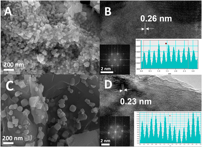
FIGURE 2. (A) SEM image, (B) HRTEM image (inset: FFT analysis and intensity-line profile) for Mo2C-Mo2N0.92 sample, (C) SEM image, (D) HRTEM image (inset: FFT analysis and intensity-line profile) for Mo2N0.92-Mo2C sample.
3.2 Electrochemical NRR performance
Electrochemical NRR performances of the prepared electrocatalysts were performed under constant N2 purging. Linear sweep voltammetry (LSV) performed under Ar- and N2-saturated electrolyte reveals a lower onset with higher current density under N2 saturation for Mo2C-Mo2N0.92 electrocatalyst due to the occurrence of NRR (Figure 3A). NRR performances were quantified by the chronoamperometric (CA) measurements performed for 2 h under N2-saturation at various applied potentials. The electrolytes were sampled for ammonia quantification by UV-colorimetric analysis using a commercial ammonia test kit. The ammonia calibration graphs were derived using known ammonia concentrations with a UV-vis spectrometer (Supplementary Figure S1). UV-vis spectra for the sampled electrolytes under various potentials were observed to display varied intensities indicating the concentration of ammonia. The ammonia concentration was calculated from the calibration graphs, and the ammonia yield rate and FE from Equation 2 and Equation 3, respectively. Figures 3B, C represent the CA curves and UV plots for Mo2C-Mo2N0.92 electrocatalyst at various applied potentials, respectively. Similarly, the LSV curves for Mo2N0.92-Mo2C electrocatalyst reveal a higher current density under N2-saturation, indicating NRR (Figure 3D). Figures 3E, F represents the CA plots and corresponding UV curves for the prepared Mo2N0.92-Mo2C electrocatalyst for ammonia quantification.

FIGURE 3. (A) LSV curves, (B) CA tests at various applied potentials, (C) UV-vis plots for corresponding CA test samples for Mo2C-Mo2N0.92 electrocatalyst. (D) LSV curves, (E) CA tests at various applied potentials, and (F) UV-vis plots for corresponding CA test samples for Mo2N0.92-Mo2C electrocatalyst.
Figure 4A represents ammonia yield rates and FE of Mo2C-Mo2N0.92 and Mo2N0.92-Mo2C electrocatalysts for various applied potentials, respectively. A maximum ammonia yield of about 9.6 μg h-1 cm-2 and 6.61 μg h-1 cm-2 at −0.3 V vs. RHE was observed for Mo2C-Mo2N0.92 and Mo2N0.92-Mo2C electrocatalyst, respectively. Consequently, a maximum FE of about 10.15% and 4.21% at −0.1 V vs. RHE was observed for Mo2C-Mo2N0.92 and Mo2N0.92-Mo2C electrocatalyst, respectively. A comparatively high current density was observed under N2 flow but a lower FE for ammonia of about 4.21% was observed at −0.1 V vs. RHE for Mo2N0.92-Mo2C electrocatalyst. HER is kinetically favorable due to the comparatively low potential required for H2 evolution than to dissociate the stable triple bonds of N2. Thereby, the low FE for ammonia can be attributed to the undesired HER with increasing negative potentials. Moreover, the particle sizes of Mo2C-Mo2N0.92 and Mo2N0.92-Mo2C from SEM images were observed to be 50 nm and 110 nm, respectively. It is suggested that a smaller size of the particles enables higher surface area and high exposure of active sites to drive the required electrochemical reactions. Consequently, Mo2C-Mo2N0.92 electrocatalysts with a particle size of about 50 nm exhibits a higher NRR performance compared to Mo2N0.92-Mo2C electrocatalysts with a higher particle size of about 110 nm. Therefore, particle sizes play an important role in determining the effective NRR performances for Mo2C-Mo2N0.92 electrocatalysts.
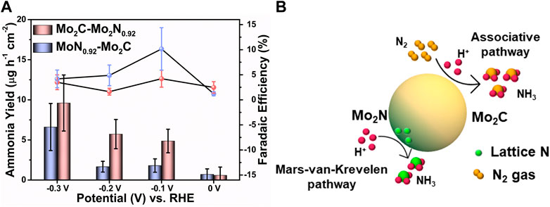
FIGURE 4. (A) Comparison of the ammonia yield and FE of Mo2C-Mo2N0.92 and Mo2N0.92-Mo2C electrocatalysts for various applied potentials. (Error bars indicate the range of values after three independent experiments) (B) Schematic illustration of NRR mechanism over Mo2C-Mo2N electrocatalyst.
Besides, a comparatively lower ammonia yield and FE was observed for Mo2N0.92-Mo2C electrocatalyst, which can be due to the less activity of Mo2N0.92 phases for N2 reduction. The NRR performances for bare Mo2C and bare Ni foam were analyzed, which reveal a maximum ammonia yield of about 4.53 μg h-1 cm-2 and 0.07 μg h-1 cm-2 and FE of about 0.14% and 0.03%, respectively (Supplementary Figure S2). This poor NRR performance for bare Mo2C and bare Ni foam substrate indicates the synergistic activity of the Mo2C-Mo2N0.92 electrocatalyst. Figure 4B illustrates the NRR mechanism in the prepared Mo2C-Mo2N0.92 heterostructures. The Mo2C phases in the Mo2C-Mo2N0.92 electrocatalyst generate ammonia by the electrochemical associative pathway by protonating the external N2 gas and the Mo2N phases following the MvK pathway by protonating the lattice-N to ammonia.
Mo2C-Mo2N0.92 electrocatalyst has revealed considerably higher NRR performances due to the combined activity of the Mo2C and Mo2N0.92 phases. N2 adsorption and activation over an electrocatalyst surface occur at the exposed active sites. Previous studies have observed a strong N2 adsorption behavior for Mo2C, which reveals a promising NRR electrocatalyst (Wan et al., 2022). Especially, the electron-rich Mo atoms with moderate H adsorption energy and high N2 affinity are the main electrocatalytic active sites for NRR (Ma et al., 2020; Liu et al., 2021; Zhang et al., 2018a).
NRR takes place by the ‘acceptance-donation’ mechanism at the Mo active sites is explained as follows. The lone pair of electrons from the σ-orbitals of N2 are donated into the empty d-orbitals of Mo, resembling acceptance, followed by the back-donation of the d-orbital electrons into the π* orbitals of N2, resembling donation (Fan et al., 2022; Wan et al., 2022). This acceptance-donation mechanism over Mo active centers results in the activation of the highly stable triple bonds of N2 and realizes an increase in bond length ((Mo)-N=N•), as shown in Equation 7. The chemisorbed N2 on Mo active sites is further protonated by six proton-coupled electron transfer steps (PCET) to form ammonia (Equation 8) by associative mechanism (Cheng et al., 2018; Ren et al., 2019).
The associative mechanism for ammonia production over the Mo electrocatalytic active sites can be suggested as follows. Further, the activated N2 can follow either an alternating protonating pathway or a distal protonating pathway.
Distal associative pathway
Alternating associative pathway
In the distal associative pathway, the protonation occurs from the farther side of the activated N atom (Equations 9-11). The protonation of the N atom bonded to the active site initiates only after complete protonation and ammonia evolution of the farthest N atom (Equations 12–14). In the alternating pathway, the protonation occurs alternatively on both N atoms and ammonia is generated at the final successive steps (Equations 15–19). Typically, the charge transfer reaction takes place via the charge accumulation and depletion stages in both Mo and N atoms attributing to better NRR performances (Wan et al., 2022).
Besides, Mo2N0.92 is suggested to generate ammonia by decomposition of the Mo2N lattice rather than by catalytic mechanism (Zhang et al., 2018b; Hu et al., 2019). Thereby, the Mo2N0.92 entity present in the Mo2C-Mo2N0.92 electrocatalyst generates ammonia by the Mars-van-Krevelen (MvK) mechanism. By the MvK mechanism, the lattice N atoms in metal nitride electrocatalysts are protonated rather than the conversion of gaseous N2 to form ammonia (Equations 20–22) (Yang et al., 2019). The detailed MvK mechanism over Mo2N phases is elucidated as follows.
Where Mo2* represents the nitrogen vacancy formed due to the MvK mechanism. The surface replenishment of the nitrogen vacancies from N2 occurs, which generates ammonia (Equation 23) (Abghoui et al., 2016). In cases due to low N2 solubility in aqueous electrolytes, the surface nitrogen vacancies are replaced by the N atoms from the bulk resulting in the degradation of the electrocatalyst over time. Thereby, the surface replenished N is then protonated to release ammonia (Equations 24–26). Besides, the MvK mechanism demands high energy for NRR, which facilitates HER at higher potentials (Ren et al., 2018). Nitrogen vacancies affect the neighboring N atoms in the lattice resulting in poor electrocatalytic performances (Ren et al., 2018). As a result, an increased ammonia yield due to the heterostructure formation can be ascribed to the combined contribution from electrochemical N2 reduction and the MvK mechanism. The NRR performances in the prepared Mo2C-Mo2N0.92 electrocatalysts reveal the combined activity of the Mo2C and Mo2N0.92 phases. Hence, the combined electrochemical associative mechanism for N2 reduction via Mo2C and the MvK pathway by lattice-N protonation via Mo2N0.92 resulted in a high ammonia yield compared to the pristine counterparts.
3.3 Electrochemical characterization
Electrochemical impedance spectroscopy (EIS) analysis was undergone to elucidate the impedance characteristics of the prepared electrocatalysts. The Nyquist plots for real part (Z′) and imaginary part (Z”) of impedance elucidate the charge transfer and diffusion characteristics of the prepared electrocatalysts. The initial intercept on Z’ axis at the high frequency region denotes the solution resistance (Rs) in the electrode and electrolyte interface. Besides, the diameter of the semi-circle in the mid-frequency region denotes the charge transfer resistance (Rct) for the redox reactions between the active sites of the electrode and the electrolytic ions. Additionally, the linear curve in the low frequency region ascribes to the diffusion characteristics of the prepared electrocatalysts.
From the Nyquist plots in Figure 5A, Mo2C-Mo2N0.92 electrocatalyst exhibits a low Rs value of about 11 Ω compared to Mo2N0.92-Mo2C (15 Ω) electrocatalyst. Besides, the Mo2C-Mo2N0.92 electrocatalyst reveals Rct value of about 4.5 Ω which is very less compared to 6.5 Ω for Mo2N0.92-Mo2C electrocatalyst. Thereby, the Mo2C-Mo2N0.92 electrocatalyst is observed to exhibit faster electrocatalytic redox reactions superior to Mo2N0.92-Mo2C electrocatalyst. The superior electrocatalytic activity of the dominant Mo2C phases in Mo2C-Mo2N0.92 electrocatalyst explains the reduced resistance for redox reactions. Additionally, a higher angle for the linear curve with respect to x-axis was observed for Mo2C-Mo2N0.92 in the low frequency region compared to Mo2N0.92-Mo2C which indicate the superior diffusion characteristics of the Mo2C-Mo2N0.92 electrocatalyst.
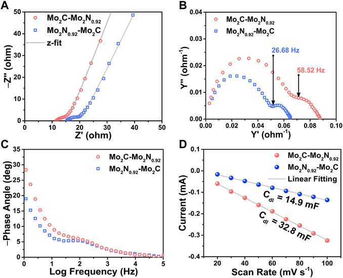
FIGURE 5. (A) Nyquist impedance plots, (B) Nyquist admittance plots, and (C) Bode plots for the prepared Mo2C-Mo2N0.92 and Mo2N0.92-Mo2C electrocatalysts, respectively. (D) Current vs. scan rate plots derived from CV curves performed at various scan rates.
The Nyquist admittance plots explain the conductivity of the prepared electrocatalysts as a function of frequency. The admittance plot is characterized by the knee frequency which elucidate the corresponding charge transfer resistances of the prepared electrocatalysts. From Figure 5B, the Mo2C-Mo2N0.92 electrocatalyst displays a higher knee frequency at 58.52 Hz compared to Mo2N0.92-Mo2C (26.68 Hz). The higher knee frequency substantiates the lower charge transfer resistance for Mo2C-Mo2N0.92 electrocatalyst which agrees with the Nyquist plots. The Bode phase plot in Figure 5C for the prepared electrocatalysts were obtained from the phase angle vs. frequency plots to elucidate the frequency response of the electrocatalyst. The phase angle denotes the phase difference between the current and voltage of the electrochemical cell. A phase angle of −90° denotes the ideal capacitor behavior elucidating a double-layer capacitance (Cdl). The curves in the low frequency region of the Bode phase plot denote the double layer capacitance(Cdl) of the electrocatalyst and the curves in high frequency region denote the capacitance in the redox reactions. Thereby, the Bode phase plots suggest a slight phase angle shift towards high frequencies for Mo2C-Mo2N0.92 electrocatalyst than Mo2N0.92-Mo2C indicating faster reaction kinetics. Hence, the dominant phases of Mo2C in Mo2C-Mo2N0.92 electrocatalyst drives a faster reaction kinetics than the Mo2N0.92 phases which validate the previous electrochemical studies.
Electrochemical active surface area (ECSA) of the prepared electrocatalysts were measured to estimate the available surface area for electrochemical reactions. ECSA was estimated by calculating the double layer capacitance (Cdl) of the prepared electrocatalysts by performing CV tests for various scan rates in the non-faradaic region, as shown in Figure 5D (Supplementary Figure S3). The current response in the non-faradaic region is purely due to the charge/discharge of the double layer. Thereby, the Cdl value (mF) was estimated from the slope of the linear plot of scan rate vs. current density derived from the CV curves. Consequently, the ratio of the Cdl value and the specific capacitance (40 μF cm-2) yields ECSA value of the prepared electrocatalyst. As per the discussion, the electrocatalysts exhibit Cdl values of about 32.8 mF and 14.9 mF for Mo2C-Mo2N0.92 and Mo2N0.92-Mo2C, respectively. Consequently, the electrocatalysts exhibit a high ECSA value of about 820 cm2 and 372.5 cm2 for Mo2C-Mo2N0.92 and Mo2N0.92-Mo2C electrocatalyst, respectively. Thereby, a high ECSA value attributes to higher exposure of active sites to the electrolytic ions for redox reactions.
4 Conclusion
In summary, the prepared Mo2C-Mo2N0.92 electrocatalyst was synthesized by urea glass route under varying urea amounts followed by pyrolysis at 800°C under an N2 atmosphere. The structural analysis reveals the formation of well-matched phases for Mo2C-Mo2N0.92 samples respectively. The morphological and microstructure analysis reveals the formation of nanocomposites and well-defined lattice planes for Mo2C-Mo2N0.92. The chemical state analysis of the prepared samples reveal the presence of metallic Mo bonds in addition to Mo2N and Mo2C. The electron-rich Mo sites act as the active sites for electrocatalytic NRR activity. NRR performances reveal a maximum ammonia yield of around 9.6 μg h-1 cm-2 at −0.3 V vs. RHE and an FE of about 10.15% at −0.1 V vs. RHE for Mo2C-Mo2N0.95 electrocatalyst, respectively. The improved NRR performances were attributed to the synergistic activity of the Mo2C and Mo2N0.92 moieties, which is verified by the NRR activity of the single-phase Mo2C sample. Therefore, this study recommends the superior electrocatalytic activity of the tailored transition metal carbide and nitride electrocatalysts which could be further engineered to achieve efficient electrocatalysis.
Data availability statement
The raw data supporting the conclusions of this article will be made available by the authors, without undue reservation.
Author contributions
TA, SS, JK, and US contributed to conception and design of the study. TA and SS organized the database. TA performed the statistical analysis. TA and SS wrote the first draft of the manuscript. TA, SS, SJ, HL, DM, JK, and US wrote sections of the manuscript. All authors contributed to manuscript revision, read, and approved the submitted version.
Funding
This work was supported by the National Research Foundation of Korea grant funded by the Ministry of Science and the Korean Government (MSIT), Republic of Korea (NRF-2021R1I1A1A01047527 and 2022R1A2C1012419) and New & Renewable Energy Core Technology Program of the Korea Institute of Energy Technology Evaluation and Planning (KETEP) granted financial resource from Ministry of Trade, Industry and Energy, Republic of Korea (No. 20213030040590). This work was also supported by the KENTECH Research Grant funded by the Korea Institute of Energy Technology, Republic of Korea (KRG 2022–01–016). Following are results of a study on the “Leaders in INdustry-university Cooperation 3.0” Project, supported by the Ministry of Education and National Research Foundation of Korea. This work was also supported by Development of high-power capacitor (supercapacitor) performance enhancement technology customized for companies by the Ministry of Trade, Industry and Energy and Korea Evaluation Institute of Industrial Technology [Project No: 00155725/Project Name: Development of battery capacitors for long-term, high-capacity, and high power energy storage system.
Conflict of interest
The authors declare that the research was conducted in the absence of any commercial or financial relationships that could be construed as a potential conflict of interest.
Publisher’s note
All claims expressed in this article are solely those of the authors and do not necessarily represent those of their affiliated organizations, or those of the publisher, the editors and the reviewers. Any product that may be evaluated in this article, or claim that may be made by its manufacturer, is not guaranteed or endorsed by the publisher.
Supplementary material
The Supplementary Material for this article can be found online at: https://www.frontiersin.org/articles/10.3389/fchem.2023.1122150/full#supplementary-material
References
Abghoui, Y., Garden, A. L., Howalt, J. G., Vegge, T., and Skúlason, E. (2016). Electroreduction of N2 to ammonia at ambient conditions on mononitrides of Zr, Nb, Cr, and V: A dft guide for experiments. ACS Catal. 6, 635–646. doi:10.1021/acscatal.5b01918
Arif, M., Babar, M., Azhar, U., Sagir, M., Bilal Tahir, M., Asim Mushtaq, M., et al. (2023). Rational design and modulation strategies of Mo-based electrocatalysts and photo/electrocatalysts towards nitrogen reduction to ammonia (NH3). Chem. Eng. J. 451, 138320. doi:10.1016/j.cej.2022.138320
Avery, W. H. (1988). A role for ammonia in the hydrogen economy. Int. J. Hydrogen Energy 13, 761–773. doi:10.1016/0360-3199(88)90037-7
Chen, S., Zhou, Z., Bai, B., Dai, Z., and Shi, J. (2022). In-situ-generated MoO2 on MoS2/ZnO heterostructures with enriched S,O-vacancies for enhanced electrocatalytic reduction of N2 to NH3. ChemElectroChem 9, e202200625. doi:10.1002/celc.202200625
Cheng, H., Ding, L.-X., Chen, G.-F., Zhang, L., Xue, J., and Wang, H. (2018). Molybdenum carbide nanodots enable efficient electrocatalytic nitrogen fixation under ambient conditions. Adv. Mater. 30, 1803694. doi:10.1002/adma.201803694
Chu, K., Li, X., Tian, Y., Li, Q., and Guo, Y. (2022). Boron nitride quantum dots/Ti3C2tx-MXene heterostructure for efficient electrocatalytic nitrogen fixation. ENERGY and Environ. Mater. 5, 1303–1309. doi:10.1002/eem2.12247
Cui, X., Tang, C., and Zhang, Q. (2018). A review of electrocatalytic reduction of dinitrogen to ammonia under ambient conditions. Adv. Energy Mater. 8, 1800369. doi:10.1002/aenm.201800369
Du, L., Xing, L., Zhang, G., Liu, X., Rawach, D., and Sun, S. (2021). Engineering of electrocatalyst/electrolyte interface for ambient ammonia synthesis. SusMat 1, 150–173. doi:10.1002/sus2.7
Fan, B., Wang, H., Zhang, H., Song, Y., Zheng, X., Li, C., et al. (2022). Phase transfer of Mo2C induced by boron doping to boost nitrogen reduction reaction catalytic activity. Adv. Funct. Mater. 32, 2110783. doi:10.1002/adfm.202110783
Fiksel, J., Bruins, R., Gatchett, A., Gilliland, A., and ten Brink, M. (2014). The triple value model: A systems approach to sustainable solutions. Clean Technol. Environ. Policy 16, 691–702.
Giordano, C., Erpen, C., Yao, W., and Antonietti, M. (2008). Synthesis of Mo and W carbide and nitride nanoparticles via a simple “urea glass” route. Nano Lett. 8, 4659–4663. doi:10.1021/nl8018593
Guo, X., Wan, X., and Shui, J. (2021). Molybdenum-based materials for electrocatalytic nitrogen reduction reaction. Cell Rep. Phys. Sci. 2, 100447. doi:10.1016/j.xcrp.2021.100447
Hargreaves, J. S. J. (2013). Heterogeneous catalysis with metal nitrides. Coord. Chem. Rev. 257, 2015–2031. doi:10.1016/j.ccr.2012.10.005
Hinnemann, B., and Nørskov, J. K. (2006). Catalysis by enzymes: The biological ammonia synthesis. Top. Catal. 37, 55–70. doi:10.1007/s11244-006-0002-0
Hu, B., Hu, M., Seefeldt, L., and Liu, T. L. (2019). Electrochemical dinitrogen reduction to ammonia by Mo2N: Catalysis or decomposition? ACS Energy Lett. 4, 1053–1054. doi:10.1021/acsenergylett.9b00648
Huo, L., Liu, B., Zhang, G., and Zhang, J. (2016). Universal strategy to fabricate a two-dimensional layered mesoporous Mo2C electrocatalyst hybridized on graphene sheets with high activity and durability for hydrogen generation. ACS Appl. Mater. Interfaces 8, 18107–18118. doi:10.1021/acsami.6b05007
Kandemir, T., Schuster, M. E., Senyshyn, A., Behrens, M., and Schlögl, R. (2013). The haber–bosch process revisited: On the real structure and stability of “ammonia iron” under working conditions. Angew. Chem. Int. Ed. 52, 12723–12726. doi:10.1002/anie.201305812
Liu, J., Kong, W., Jin, Z., Han, Y., Sun, J., Ma, L., et al. (2020). A MoFe nitrogenase-mimicking electrocatalyst for nitrogen fixation with high faradaic efficiency. J. Mater. Chem. A 8, 19278–19282. doi:10.1039/d0ta07757g
Liu, W., Wang, X., Wang, F., Du, K., Zhang, Z., Guo, Y., et al. (2021). A durable and pH-universal self-standing MoC–Mo2C heterojunction electrode for efficient hydrogen evolution reaction. Nat. Commun. 12, 6776. doi:10.1038/s41467-021-27118-6
Ma, Y., Yang, T., Zou, H., Zang, W., Kou, Z., Mao, L., et al. (2020). Synergizing Mo single atoms and Mo2C nanoparticles on CNTs synchronizes selectivity and activity of electrocatalytic N2 reduction to ammonia. Adv. Mater. 32, 2002177. doi:10.1002/adma.202002177
MacFarlane, D. R., Cherepanov, P. V., Choi, J., Suryanto, B. H. R., Hodgetts, R. Y., Bakker, J. M., et al. (2020). A roadmap to the ammonia economy. Joule 4, 1186–1205. doi:10.1016/j.joule.2020.04.004
Mtukula, A. C., Bo, X., and Guo, L. (2017). Highly active non-precious metal electrocatalyst for the hydrogen evolution reaction based on nitrogen-doped graphene supported MoO2/WN/Mo2N. J. Alloys Compd. 692, 614–621. doi:10.1016/j.jallcom.2016.09.079
Ren, X., Cui, G., Chen, L., Xie, F., Wei, Q., Tian, Z., et al. (2018). Electrochemical N2 fixation to NH3 under ambient conditions: Mo2N nanorod as a highly efficient and selective catalyst. Chem. Commun. 54, 8474–8477. doi:10.1039/c8cc03627f
Ren, X., Zhao, J., Wei, Q., Ma, Y., Guo, H., Liu, Q., et al. (2019). High-performance N2-to-NH3 conversion electrocatalyzed by Mo2C nanorod. ACS Central Sci. 5, 116–121. doi:10.1021/acscentsci.8b00734
Ren, Y., Yu, C., Tan, X., Huang, H., Wei, Q., and Qiu, J. (2021). Strategies to suppress hydrogen evolution for highly selective electrocatalytic nitrogen reduction: Challenges and perspectives. Energy and Environ. Sci. 14, 1176–1193. doi:10.1039/d0ee03596c
Safari, A., Das, N., Langhelle, O., Roy, J., and Assadi, M. (2019). Natural gas: A transition fuel for sustainable energy system transformation? Energy Sci. Eng. 7, 1075–1094. doi:10.1002/ese3.380
Sardar, K., Dan, M., Schwenzer, B., and Rao, C. N. R. (2005). A simple single-source precursor route to the nanostructures of AlN, GaN and InN. J. Mater. Chem. 15, 2175–2177. doi:10.1039/b502887f
Su, D., Zhang, X., Wu, A., Yan, H., Liu, Z., Wang, L., et al. (2019). CoO-Mo2N hollow heterostructure for high-efficiency electrocatalytic hydrogen evolution reaction. NPG Asia Mater. 11, 78. doi:10.1038/s41427-019-0177-z
Wan, Y., Wang, Z., Li, J., and Lv, R. (2022). Mo2C-MoO2 heterostructure quantum dots for enhanced electrocatalytic nitrogen reduction to ammonia. ACS Nano 16, 643–654. doi:10.1021/acsnano.1c07973
Wang, T., Wang, P., Zang, W., Li, X., Chen, D., Kou, Z., et al. (2022). Nanoframes of Co3O4–Mo2N heterointerfaces enable high-performance bifunctionality toward both electrocatalytic HER and OER. Adv. Funct. Mater. 32, 2107382. doi:10.1002/adfm.202107382
Yang, X., Kattel, S., Nash, J., Chang, X., Lee, J. H., Yan, Y., et al. (2019). Quantification of active sites and elucidation of the reaction mechanism of the electrochemical nitrogen reduction reaction on vanadium nitride. Angew. Chem. Int. Ed. 58, 13906–13910. doi:10.1002/ange.201906449
Ye, T., Ba, K., Yang, X., Xiao, T., Sun, Y., Liu, H., et al. (2023). Valence engineering at the interface of MoS2/Mo2C heterostructure for bionic nitrogen reduction. Chem. Eng. J. 452, 139515. doi:10.1016/j.cej.2022.139515
Yesudoss, D. K., Lee, G., and Shanmugam, S. (2021). Strong catalyst support interactions in defect-rich γ-Mo2N nanoparticles loaded 2D-h-BN hybrid for highly selective nitrogen reduction reaction. Appl. Catal. B Environ. 287, 119952. doi:10.1016/j.apcatb.2021.119952
Yuan, S., Xia, M., Liu, Z., Wang, K., Xiang, L., Huang, G., et al. (2022). Dual synergistic effects between Co and Mo2C in Co/Mo2C heterostructure for electrocatalytic overall water splitting. Chem. Eng. J. 430, 132697. doi:10.1016/j.cej.2021.132697
Yue, M., Lambert, H., Pahon, E., Roche, R., Jemei, S., and Hissel, D. (2021). Hydrogen energy systems: A critical review of technologies, applications, trends and challenges. Renew. Sustain. Energy Rev. 146, 111180. doi:10.1016/j.rser.2021.111180
Zhang, L., Ji, X., Ren, X., Luo, Y., Shi, X., Asiri, A. M., et al. (2018). Efficient electrochemical N2 reduction to NH3 on Mon nanosheets array under ambient conditions. ACS Sustain. Chem. Eng. 6, 9550–9554. doi:10.1021/acssuschemeng.8b01438
Zhang, L., Ji, X., Ren, X., Ma, Y., Shi, X., Tian, Z., et al. (2018). Electrochemical ammonia synthesis via nitrogen reduction reaction on a MoS2 catalyst: Theoretical and experimental studies. Adv. Mater. 30, 1800191. doi:10.1002/adma.201800191
Zhang, Y., Guo, P., Guo, S., Xin, X., Wang, Y., Huang, W., et al. (2022). Gradient heating epitaxial growth gives well lattice-matched Mo2C−Mo2N heterointerfaces that boost both electrocatalytic hydrogen evolution and water vapor splitting. Angew. Chem. Int. Ed. 61, e202209703. doi:10.1002/anie.202209703
Zhao, Y., Setzler, B. P., Wang, J., Nash, J., Wang, T., Xu, B., et al. (2019). An efficient direct ammonia fuel cell for affordable carbon-neutral transportation. Joule 3, 2472–2484. doi:10.1016/j.joule.2019.07.005
Keywords: ammonia electrosynthesis, electrocatalyst, electrochemical nitrogen reduction reaction, heterostructures, Mo2C catalyst, Mo2N catalyst
Citation: An T-Y, Surendran S, Jesudass SC, Lee H, Moon DJ, Kim JK and Sim U (2023) Promoting electrochemical ammonia synthesis by synergized performances of Mo2C-Mo2N heterostructure. Front. Chem. 11:1122150. doi: 10.3389/fchem.2023.1122150
Received: 12 December 2022; Accepted: 25 January 2023;
Published: 16 February 2023.
Edited by:
Kyoungsuk Jin, Korea University, Republic of KoreaReviewed by:
Chan Woo Lee, Kookmin University, Republic of KoreaHee Jo Song, Sejong University, Republic of Korea
Copyright © 2023 An, Surendran, Jesudass, Lee, Moon, Kim and Sim. This is an open-access article distributed under the terms of the Creative Commons Attribution License (CC BY). The use, distribution or reproduction in other forums is permitted, provided the original author(s) and the copyright owner(s) are credited and that the original publication in this journal is cited, in accordance with accepted academic practice. No use, distribution or reproduction is permitted which does not comply with these terms.
*Correspondence: Jung Kyu Kim, bGVna2ltQHNra3UuZWR1; Uk Sim, dXNpbUBrZW50ZWNoLmFjLmty
†These authors have contributed equally to this work