 Jun Huang
 Yufan Zhang
95% of researchers rate our articles as excellent or good
Learn more about the work of our research integrity team to safeguard the quality of each article we publish.
Find out more
ORIGINAL RESEARCH article
Front. Chem. , 25 July 2022
Sec. Electrochemistry
Volume 10 - 2022 | https://doi.org/10.3389/fchem.2022.938064
This article is part of the Research Topic Rising stars in Electrochemistry 2021 View all 5 articles
We ponder over how an electrochemical cell conforms itself to the open-circuit voltage (OCV) given by the Nernst equation, where properties of the electrodes play no role. We first show, via a pedagogical derivation of the Nernst equation, how electrode properties are canceled and then take a closer look into the electrode–electrolyte interface at one electrode by linking charge and potential distributions. We obtain an equilibrium Poisson–Nernst equation that shows how the charge distribution across an electrode–electrolyte interface can be dictated by the chemical potentials of redox species. Taking a
Many concepts in electrochemistry appear simple, but they are more complicated than they seem. One example is the electrode potential, which is among the first concepts we will encounter when opening any introductory electrochemistry textbook. However, the definition of absolute electrode potential had been extensively discussed in the 1970s–1980s (Trasatti, 1980; 1982; Trasatti, 1986a;b; Trasatti, 1986c; 1990). To illustrate, Trasatti (1990) stated that “the present author has considerably contributed to the discussion with several papers during the last 15 years in an attempt to bring the various views back to a unifying approach.” Trasatti’s formal theory states that “the absolute electrode potential is the difference in electronic energy between a point inside the metal (Fermi level) and a point outside the solution.” This definition has been adopted in the recommendation of The International Union of Pure and Applied Chemistry (IUPAC) (Trasatti, 1986a).
There is another “familiar stranger,” namely, the open-circuit voltage (OCV) of an electrochemical cell, which is simply the potential difference between two terminals of the cell under the open-circuit condition. Though the definition is unequivocal and the measurement easily accessible, the obtained value can be elusive and its interpretation disputed. A famous example is the OCV of a hydrogen/oxygen fuel cell at rest, also called the rest potential: why is the measured value significantly lower, by several hundreds of millivolts, than the thermodynamic value of 1.23 V versus the standard hydrogen electrode (SHE)?
James Hoare systematically investigated this problem in the 1960s–1970s (Hoare, 1962; Hoare, 1963; Hoare, 1964a; Hoare, 1964b; Hoare, 1964c; Thacker and Hoare, 1971; Hoare, 1974; Hoare, 1978). He concluded that the measured rest potential is a mixed potential of the oxygen reduction reaction and another parasitic reaction, namely, water dissociation reaction forming adsorbed hydroxyl. There are continued interests in understanding the rest potential of practical fuel cells beyond the glass cells used in Hoare’s experiments (Zhang et al., 2006; Vilekar and Datta, 2010; Reimer et al., 2019). In these practical situations, other factors such as hydrogen crossover come into play.
As an established fact, the OCV of the full cell calculated by the Nernst equation is independent of electrode properties, such as the chemical potential of electrons, the work function, and the valency electron density. For example, the OCV of a hydrogen/oxygen fuel cell under standard conditions is 1.23 V, regardless of the electrode materials. A seemingly naïve question might be asked:
How does the OCV of an electrochemical cell abide by the Nernst equation by canceling off all electrode-specific properties in an amazingly precise manner?
Though the answer to this question is self-evident, as thermodynamic quantities should be path-independent, a revisit of it from an alternative view is not meaningless. It may reveal something interesting. This question is discussed herein by first presenting a pedagogical derivation of the OCV of a general electrochemical cell. By decomposing the OCV into several parts, we show explicitly how electrode-specific properties cancel each other. Further delving into the electrode–electrolyte interface at one electrode, we link the potential difference between electrode and electrolyte phases with the net charge distribution at the electrode–electrolyte interface, which is then correlated with the chemical potentials of redox species involved in the reaction occurring on this electrode. The formal analysis is then demystified by taking an H2/O2 fuel cell as an example. In this example, we run into a weird point that two identical platinum electrodes constituting a hydrogen-oxygen fuel cell have different potentials of zero charge. We close this essay by commenting on why Trasatti’s relationship between the potential of the zero charge of an electrochemical interface and the work function of metals does not apply to the present case.
For an overall electrochemical reaction
with
where
Now, we will formulate the OCV in another way and decouple it into a serial connection of several potential differences. OCV is measured by connecting the cathode and anode with a voltmeter, as shown in Figure 1. The voltmeter has extremely high resistance, so a circuit connected with it allows for negligible current and thereby can be taken as an open circuit. The wires that connect the voltmeter with the two electrodes are of the same metal. The value on the voltmeter, herein the OCV, is expressed by the difference in the Fermi levels of these two wires:
with
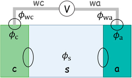
FIGURE 1. Schematic of an electrochemical cell. A voltmeter connects the cathode and anode to measure the open-circuit potential. The two wires of the voltmeter are made of the same metal.
The difference in the potential in two metal wires can be decoupled into a serial connection of four potential differences:
with
The metal contact potential difference can be formulated with the condition that the electrons in connected metals are in electrochemical equilibrium (or Fermi levels align):
Combining Eqs 7, 8, the two chemical potentials in metal wires are canceled:
We update Eq. 5 with the help of Eqs 6, 9:
where
Considering a redox couple in equilibrium on the cathode side,
Some rearrangements give
In the same vein,
Inserting Eqs 12, 13 back to Eq. 10,
Shown above is how all electrode-specific properties, namely,
Of note, a usual misunderstanding of the OCV reads
Next, we look further into
where
We take some more lines to explain Eq. 16. This electrode–solution dichotomy of the net charge distribution is proper for the case without ion-specific adsorption.
For the cases with ion-specific adsorption, chemical bonds are formed between the electrode and specifically adsorbed ions. In general, the specifically adsorbed ions are not electroneutral but still possess a fraction of charge (Schmickler and Guidelli, 2014). It then becomes principally difficult to separate
For a one-dimensional case without ion-specific adsorption, where
In bulk solution,
Integrating again from
with
As no assumption on the condition of the interfacial reaction is made in the derivation, Eq. 19 is valid under both equilibrium and nonequilibrium conditions.
It has been established that the potential difference across the electrode–solution interface
Eq. 20 implies that
Based on Eq. 20, two corollaries can be made: 1) for two electrodes of the same material where different redox species are in equilibrium, the net charge distribution will be different and 2) for two electrodes of different materials, even if the redox species—with whom they have established equilibrium—are the same, the net charge distribution will be different.
In order to understand the first corollary from a microscopic perspective, it is instructive to consider an H2/O2 fuel cell, schematically shown in Figure 2. Both electrodes made of platinum are immersed in an acidic solution with pH = 0. The cell is kept under the open-circuit condition.
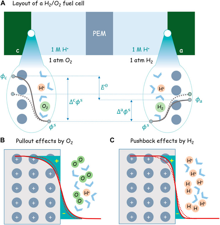
FIGURE 2. (A) Layout of an H2/O2 fuel cell under the standard condition (1 atm O2, 1 atm H2, 1M H+, and 25 °C). The solid and dashed gray lines denote, respectively, the potential distribution before and after H2 and O2 are injected into the cell. PEM is short for the proton exchange membrane. The schematically shown
At the outset, no H2/O2 gas has been injected into the cell and dissolved in the solution. Therefore, the anode and cathode sides are totally symmetric in terms of electrode material and electrolyte component. Therefore, regardless of any reaction that may occur at both interfaces, we can safely state that
Meanwhile, dashed lines in Figures 2B,C show schematically the electron density distribution at both electrodes for this symmetric case. The detailed charge distributions can be calculated using first-principles simulations based on the density-functional theory (DFT) (Le et al., 2017; Sakong and Groß, 2018, 2020; Le et al., 2021).
From now on, let oxygen and hydrogen gas come in the cathode and anode compartments while the external electric circuit is still kept open. The redox couple of
Using Eq. 9 and recalling the two electrodes as both made of Pt, that is,
The differences between
After introducing hydrogen and oxygen into the anode and cathode, hydrogen repels metal electrons back into the metal skeleton, while oxygen pulls more metal electrons out of the metal skeleton. The pullout effect by oxygen increases the surface dipole moment by increasing the distance between positively charged ionic cores and negatively charged “electron tails.” The pushback effect by the hydrogen, on the contrary, does the opposite. The uplift of
Theory and experiment revealed that the pushback effect of adsorbed hydrogen decreases the work function of Pt(111) (Li et al., 2021), whereas the pullout effect of adsorbed oxygen increases it (Malek and Eikerling, 2018). As regards the EDL at Pt(111) contacted with an acidic aqueous solution, a mean-field model has shown that chemisorption of partially charged hydroxyl and oxygen contributes an additional surface dipole moment, leading to a second pzc and an overall nonmonotonic surface charging behavior (Huang et al., 2016; Huang et al., 2018), which are confirmed in atomistic simulations (Fernandez-Alvarez and Eikerling, 2019; Tesch et al., 2021; Braunwarth et al., 2022).
Let us relook at this problem from the perspective of pzc. The pzc is defined as the potential at which no net charge is accumulated on the electrode. The anode herein is actually the standard hydrogen electrode (SHE). It has a potential of 0 V with reference to the SHE because it takes itself as the reference. Since the anode is negatively charged, it has a pzc higher than 0 V. The cathode has a potential of 1.23 V with reference to the SHE. Since it is positively charged, it has a pzc lower than 1.23 V. Due to the pullout and pushback effects, the two pzc are arguably not equal to each other.
Ostensibly, it is strange that the two electrodes, made of the same metal platinum, could have so different pzcs. The point is that the pzc is not a property of the electrode itself but a property of the electrode–electrolyte interface; the latter could be significantly changed by the electrolyte composition. That has been demonstrated in several experimental works (Smalley, 2017; Shatla et al., 2021) and discussed in a recent modeling work (Huang et al., 2020). As an immediate implication, it is ambiguous to say the pzc of an electrode material without specifying the adjacent electrolyte solution.
As a final remark, the present case where platinum can have two different pzcs contradicts Trasatti’s relationship between the pzc of an EDL and the work function of the metal constituting the EDL (Trasatti, 1971). It should be noted that Trasatti’s relationship was established for “clean” metal surfaces without adsorption or chemisorption. However, chemisorption occurs on the surfaces of two Pt electrodes for the present case where the surface structure of the metal changes from its original state. Therefore, our analysis indicates that Trasatti’s relationship does not apply to electrocatalytic EDLs, which display distinct behaviors compared to ideally polarizable EDLs at “clean” metal surfaces. For instance, no Gouy–Chapman minimum was observed in the differential double-layer capacitance curves of Pt(111), even in the so-called pure double-layer region (Pajkossy and Kolb, 2007; Ojha et al., 2020; Ojha et al., 2022). It is also important to notice that the usual pzc is measured under a closed-circuit condition, whereas the two platinum electrodes in our case are under open-circuit condition. Therefore, the pzc under the open-circuit condition could be different from that under the closed-circuit condition because the surface state of the electrodes changes.
In conclusion, we have touched upon the seemingly trivial question that how the electrochemical cell conforms itself to the OCV stipulated by the Nernst equation. We have obtained an equilibrium Poisson–Nernst equation in Eq. 20 relating the net charge distribution across the electrode–electrolyte interface to chemical potentials of redox species. Furthermore, an H2/O2 fuel cell has been used to illustrate how the OCV is generated microscopically via tuning the “electron tail,” namely, the spillover electron, in the EDL. It is important to note that the analysis has been limited to the equilibrium state under the open-circuit condition. The closed-circuit condition with charge transfer reactions occurring at both electrodes will be addressed in a separate essay.
The original contributions presented in the study are included in the article/supplementary material. Further inquiries can be directed to the corresponding author.
JH initiated this work, and YZ joined later and contributed substantially. JH wrote the first draft, which was revised by YZ. We confirmed the submission.
The authors declare that the research was conducted in the absence of any commercial or financial relationships that could be construed as a potential conflict of interest.
The handling editor VB declared a shared affiliation with the authors at the time of review.
All claims expressed in this article are solely those of the authors and do not necessarily represent those of their affiliated organizations or those of the publisher, the editors, and the reviewers. Any product that may be evaluated in this article, or claim that may be made by its manufacturer, is not guaranteed or endorsed by the publisher.
Dedicated to Professor Juan Feliu on the occasion of his official retirement from Alicante University who continues to inspire our understanding of electrochemical interfaces and reactions.
Badiali, J. P. (1987). The Jellium Model in Electrochemistry. Berichte Bunsenges. für Phys. Chem. 91, 270–276. doi:10.1002/bbpc.19870910406
Braunwarth, L., Jung, C., and Jacob, T. (2022). Potential-dependent Pt (111)—water Interface: Tackling the Challenge of a Consistent Treatment of Electrochemical Interfaces. doi:10.26434/chemrxiv-2022-xndvx
Fernandez-Alvarez, V. M., and Eikerling, M. H. (2019). Interface Properties of the Partially Oxidized Pt(111) Surface Using Hybrid DFT-Solvation Models. ACS Appl. Mat. Interfaces 11, 43774–43780. doi:10.1021/acsami.9b16326
Hoare, J. P. (1963). A Study of the Rest Potentials in the Gold-Oxygen-Acid System. J. Electrochem. Soc. 110, 245. doi:10.1149/1.2425724
Hoare, J. P. (1964b). On the Mixed Potentials Observed in the Iridium-Oxygen-Acid System. J. Electrochem. Soc. 111, 988. doi:10.1149/1.2426305
Hoare, J. P. (1978). On the Normal Oxygen Potential at a Platinum-Oxygen Alloy Diaphragm Electrode. J. Electrochem. Soc. 125, 1768–1771. doi:10.1149/1.2131291
Hoare, J. P. (1962). Rest Potentials in the Platinum-Oxygen-Acid System. J. Electrochem. Soc. 109, 858. doi:10.1149/1.2425569
Hoare, J. P. (1964c). Some Double-Layer Capacity Measurements on Platinum Electrodes. Nature 204, 71–73. doi:10.1038/204071b0
Hoare, J. P. (1964a). The Effect of Metal Dissolution on the Rest Potential in the Palladium-Oxygen-Acid System. J. Electrochem. Soc. 111, 610. doi:10.1149/1.2426193
Hoare, J. P. (1974). The Effect of Oxygen Dissolved in Pt on the Potential of a Pt∕O2 Electrode at Rest. J. Electrochem. Soc. 121, 872. doi:10.1149/1.2401940
Huang, J., Chen, S., and Eikerling, M. (2021). Grand-Canonical Model of Electrochemical Double Layers from a Hybrid Density–Potential Functional. J. Chem. Theory Comput.
Huang, J. (2021). Hybrid Density-Potential Functional Theory of Electric Double Layers. Electrochimica Acta 389, 138720. doi:10.1016/j.electacta.2021.138720
Huang, J., Li, P., and Chen, S. (2020). Potential of Zero Charge and Surface Charging Relation of Metal-Solution Interphases from a Constant-Potential Jellium-Poisson-Boltzmann Model. Phys. Rev. B 101, 125422. doi:10.1103/physrevb.101.125422
Huang, J., Malek, A., Zhang, J., and Eikerling, M. H. (2016). Non-monotonic Surface Charging Behavior of Platinum: A Paradigm Change. J. Phys. Chem. C 120, 13587–13595. doi:10.1021/acs.jpcc.6b03930
Huang, J. (2022). Surface Charging Behaviors of Electrocatalytic Interfaces with Partially Charged Chemisorbates. Curr. Opin. Electrochem. 33, 100938. doi:10.1016/j.coelec.2022.100938
Huang, J., Zhou, T., Zhang, J., and Eikerling, M. (2018). Double Layer of Platinum Electrodes: Non-monotonic Surface Charging Phenomena and Negative Double Layer Capacitance. J. Chem. Phys. 148, 044704. doi:10.1063/1.5010999
Kornyshev, A. A. (1989). Metal Electrons in the Double Layer Theory. Electrochimica Acta 34, 1829–1847. doi:10.1016/0013-4686(89)85070-4
Le, J., Iannuzzi, M., Cuesta, A., and Cheng, J. (2017). Determining Potentials of Zero Charge of Metal Electrodes versus the Standard Hydrogen Electrode from Density-Functional-Theory-Based Molecular Dynamics. Phys. Rev. Lett. 119, 016801. doi:10.1103/PhysRevLett.119.016801
Le, J. B., Fan, Q. Y., Li, J. Q., and Cheng, J. (2020). Molecular Origin of Negative Component of Helmholtz Capacitance at Electrified Pt (111)/Water Interface. Science Advances 6 (41), eabb1219.
Li, P., Huang, J., Hu, Y., and Chen, S. (2021). Establishment of the Potential of Zero Charge of Metals in Aqueous Solutions: Different Faces of Water Revealed by Ab Initio Molecular Dynamics Simulations. J. Phys. Chem. C 125, 3972–3979. doi:10.1021/acs.jpcc.0c11089
Malek, A., and Eikerling, M. H. (2018). Chemisorbed Oxygen at Pt(111): a DFT Study of Structural and Electronic Surface Properties. Electrocatalysis 9, 370–379. doi:10.1007/s12678-017-0436-0
Ojha, K., Arulmozhi, N., Aranzales, D., and Koper, M. T. M. (2020). Double Layer at the Pt(111)-Aqueous Electrolyte Interface: Potential of Zero Charge and Anomalous Gouy-Chapman Screening. Angew. Chem. Int. Ed. 59, 711–715. doi:10.1002/anie.201911929
Ojha, K., Doblhoff-Dier, K., and Koper Marc, T. M. (2022). Double-layer Structure of the Pt(111)–Aqueous Electrolyte Interface. Proc. Natl. Acad. Sci. 119, e2116016119. doi:10.1073/pnas.2116016119
Pajkossy, T., and Kolb, D. M. (2007). Double Layer Capacitance of the Platinum Group Metals in the Double Layer Region. Electrochem. Commun. 9, 1171–1174. doi:10.1016/j.elecom.2007.01.002
Reimer, U., Cai, Y., Li, R., Froning, D., and Lehnert, W. (2019). Time Dependence of the Open Circuit Potential of Platinum Disk Electrodes in Half Cell Experiments. J. Electrochem. Soc. 166, F3098–F3104. doi:10.1149/2.0121907jes
Sakong, S., and Groß, A. (2018). The Electric Double Layer at Metal-Water Interfaces Revisited Based on a Charge Polarization Scheme. J. Chem. Phys. 149, 084705. doi:10.1063/1.5040056
Sakong, S., and Groß, A. (2020). Water Structures on a Pt(111) Electrode from Ab Initio Molecular Dynamic Simulations for a Variety of Electrochemical Conditions. Phys. Chem. Chem. Phys. 22, 10431–10437. doi:10.1039/c9cp06584a
Schmickler, W. (1996). Electronic Effects in the Electric Double Layer. Chem. Rev. 96, 3177–3200. doi:10.1021/cr940408c
Schmickler, W., and Guidelli, R. (2014). The Partial Charge Transfer. Electrochimica Acta 127, 489–505. doi:10.1016/j.electacta.2014.02.057
Shatla, A. S., Landstorfer, M., and Baltruschat, H. (2021). On the Differential Capacitance and Potential of Zero Charge of Au(111) in Some Aprotic Solvents. ChemElectroChem 8, 1817–1835. doi:10.1002/celc.202100316
Smalley, J. F. (2017). Potential of Zero Charge and its Temperature Derivative for Au(111) Electrode|Alkanethiol SAM|1.0 M Aqueous Electrolyte Solution Interfaces: Impact of Electrolyte Solution Ionic Strength and its Effect on the Structure of the Modified Electrode|Electrolyte Solution Interface. J. Phys. Chem. C 121, 9260–9272. doi:10.1021/acs.jpcc.6b10954
Tesch, R., Kowalski, P. M., and Eikerling, M. H. (2021). Properties of the Pt(111)/electrolyte Electrochemical Interface Studied with a Hybrid DFT-Solvation Approach. J. Phys. Condens. Matter 33, 444004. doi:10.1088/1361-648x/ac1aa2
Thacker, R., and Hoare, J. P. (1971). Sorption of Oxygen from Solution by Noble Metals. J. Electroanal. Chem. Interfacial Electrochem. 30, 1–14. doi:10.1016/0368-1874(71)85027-x
Trasatti, S. (1986b). Components of the Absolute Electrode Potential. Conceptions and Misinterpretations. Mater. Chem. Phys. 15, 427–438. doi:10.1016/0254-0584(86)90026-x
Trasatti, S. (1986c). “Components of the Electrode Potential. Concepts and Problems,” in Trends in Interfacial Electrochemistry. Editor A. F. Silva (Dordrecht: Springer Netherlands), 1–24. doi:10.1007/978-94-009-4694-1_1
Trasatti, S. (1990). The "absolute" Electrode Potential-The End of the Story. Electrochimica Acta 35, 269–271. doi:10.1016/0013-4686(90)85069-y
Trasatti, S. (1986a). The Absolute Electrode Potential: an Explanatory Note (Recommendations 1986). Pure Appl. Chem. 58, 955–966. doi:10.1351/pac198658070955
Trasatti, S. (1982). The Concept and Physical Meaning of Absolute Electrode Potential. J. Electroanal. Chem. Interfacial Electrochem. 139, 1–13. doi:10.1016/0022-0728(82)85100-0
Trasatti, S. (1980). “The Electrode Potential,” in Comprehensive Treatise of Electrochemistry: The Double Layer. Editors J. O. M. Bockris, B. E. Conway, and E. Yeager (Boston, MA: Springer US), 45–81. doi:10.1007/978-1-4615-6684-7_2
Trasatti, S. (1971). Work Function, Electronegativity, and Electrochemical Behaviour of Metals. J. Electroanal. Chem. Interfacial Electrochem. 33, 351–378. doi:10.1016/s0022-0728(71)80123-7
Vilekar, S. A., and Datta, R. (2010). The Effect of Hydrogen Crossover on Open-Circuit Voltage in Polymer Electrolyte Membrane Fuel Cells. J. Power Sources 195, 2241–2247. doi:10.1016/j.jpowsour.2009.10.023
Keywords: open-circuit potential, electrochemical concept, electric double layer, surface charge, potential of zero charge
Citation: Huang J and Zhang Y (2022) Essays on Conceptual Electrochemistry: I. Bridging Open-Circuit Voltage of Electrochemical Cells and Charge Distribution at Electrode–Electrolyte Interfaces. Front. Chem. 10:938064. doi: 10.3389/fchem.2022.938064
Received: 06 May 2022; Accepted: 21 June 2022;
Published: 25 July 2022.
Edited by:
Valentín Briega-Martos, Helmholtz Institute Erlangen-Nürnberg for Renewable Energy (IEK-11), GermanyReviewed by:
Ricardo Alonso Martínez Hincapié, Max-Planck-Institut für Chemische Energiekonversion, GermanyCopyright © 2022 Huang and Zhang. This is an open-access article distributed under the terms of the Creative Commons Attribution License (CC BY). The use, distribution or reproduction in other forums is permitted, provided the original author(s) and the copyright owner(s) are credited and that the original publication in this journal is cited, in accordance with accepted academic practice. No use, distribution or reproduction is permitted which does not comply with these terms.
*Correspondence: Jun Huang, anUuaHVhbmdAZnotanVlbGljaC5kZQ==
Disclaimer: All claims expressed in this article are solely those of the authors and do not necessarily represent those of their affiliated organizations, or those of the publisher, the editors and the reviewers. Any product that may be evaluated in this article or claim that may be made by its manufacturer is not guaranteed or endorsed by the publisher.
Research integrity at Frontiers
Learn more about the work of our research integrity team to safeguard the quality of each article we publish.