 A. Polo1
 M. Carta
 F. Delogu
 M. A. Budroni
- 1Dipartimento di Chimica e Farmacia, Università Degli Studi di Sassari, Sassari, Italy
- 2Dipartimento di Ingegneria Meccanica, Chimica, e Dei Materiali, Università Degli Studi di Cagliari, Cagliari, Italy
Understanding the dynamics of milling bodies is key to optimize the mixing and the transfer of mechanical energy in mechanochemical processing. In this work, we present a comparative study of mechanochemical reactors driven by harmonic pendular forcing and characterized by different geometries of the lateral borders. We show that the shape of the reactor bases, either flat or curved, along with the size of the milling body and the elasticity of the collisions, represents relevant parameters that govern the dynamical regimes within the system and can control the transition from periodic to chaotic behaviors. We single out possible criteria to preserve target dynamical scenarios when the size of the milling body is changed, by adapting the relative extent of the spatial domain. This allows us to modulate the average energy of the collisions while maintaining the same dynamics and paves the way for a unifying framework to control the dynamical response in different experimental conditions. We finally explore the dynamical and energetic impact of an increasingly asymmetric mechanical force.
1 Introduction
Mechanochemistry is emerging with increasing strength as a powerful approach to the synthesis of fine chemical compounds (Friscic, 2012; James et al., 2012; Balaz et al., 2013; Boldyreva, 2013; Wang, 2013; Rightmire and Hanusa, 2016; Do and Friščić, 2017; Tan and García, 2019; Friscic et al., 2020; Porcheddu et al., 2020). In contrast with conventional chemistry in solution, which makes use of heat and light to activate and drive the chemical reaction, mechanochemical transformations are caused by the application of mechanical forces to solid phases (Thiessen et al., 1967; Butyagin, 1971; Thiessen, 1979; Boldyrev, 1983; Avvakumov, 1986; Heinicke, 1986; Michalchuck et al., 2020).
In light of the common use of manual and mechanical grinding throughout human history, and starting from the XIX century in particular (Takacs, 2013), the mechanical activation of chemistry does not represent a novelty in itself. However, the possibility to carry out chemical reactions under solventless conditions, or with a significant reduction of solvent phase, is extremely appealing now that attention to green chemistry issues is unavoidable and impossible to procrastinate (Galant et al., 2022). The evidence that mechanical processing can also open synthetic routes to chemicals and materials that cannot be prepared by more conventional methods further explains why mechanochemistry is currently experiencing vigorous growth (Gomollon-Bel, 2019;1).
Amongst the mechanical processing methods, ball milling is a popular choice. Contrary to the mechanochemistry of individual molecules, which requires extremely refined manipulation methods (Boldyreva, 2013), ball milling is an easy method for mechanical processing of granular materials (Thiessen et al., 1967; Tan and García, 2019; Friscic et al., 2020; Porcheddu et al., 2020). Widely available in a variety of sizes and designs, ball milling devices are equipped with one or more reactors that contain one or more balls. The balls collide with each other and with the reactor walls as the vessel is shaken in mono-axial, pendular or rotational modes, crushing and deforming at relatively high strain rates the powder particles trapped between the colliding surfaces (Tan and García, 2019; Friscic et al., 2020). The local non-hydrostatic mechanical stresses generated during the impact can finally result in the activation of chemical reactions depending on the intensity of mechanical forces and the physical and chemical properties of the processed material (Thiessen et al., 1967; Tan and García, 2019; Friscic et al., 2020; Porcheddu et al., 2020).
Despite the interest attracted by mechanical processing in the past 50 years, the understanding of how the mechanical energy translates into chemical reactivity is still unsatisfactory. Accordingly, new theoretical tools to understand how to design, control, and predict the development of these processes are needed (Carta et al., 2020; Carta et al., 2021).
As the activation and the progress of a given mechanochemical transformation crucially depend on the conditions experienced by powder particles at collisions and by their effective mixing, one informative approach relies on the study of the dynamics of the milling bodies responsible for dragging the powder and driving collisions.
In the past, various attempts have been made in this direction for the most widespread ball milling devices (Burgio et al., 1991; Abdellaoui and Gaffet, 1995; Courtney, 1996; Magini et al., 1996; Feng et al., 2004; Cleary et al., 2006; Sinnott et al., 2006; Boschetto et al., 2013; Broseghini et al., 2016; Zhao and Shaw, 2017). The dynamics of milling balls in the SPEX Mixer/Mill 8,000 device have also been studied in detail within a deterministic framework (Watanabe et al., 1995; Delogu et al., 1998; Concas et al., 2006). In agreement with experimental results, numerical simulations showed how balls’ trajectories and collisions at the reactor walls are sensitive to the collision elasticity degree (Rustici et al., 1996; Delogu et al., 1998; Delogu et al., 2000), which can control the transition from periodic to chaotic behaviors in the temporal displacement of the ball (Caravati et al., 1999; Manai et al., 2002). From the spatial viewpoint, these chaotic regimes showed a fingerprinting multifractal topology in the location and recurrence of collisions on the reactor walls (Budroni et al., 2014; Budroni et al., 2017).
The onset of chaotic behaviors can greatly favor an effective mixing of the granular medium inside the medium (King, 1998; Aref et al., 2017), and it is, indeed, useful for isolating parametric conditions where these regimes can occur. In this context, we propose a comparative study and classification of mill body dynamics inside reactors driven by harmonic pendular motion, which represents one class of commonly used mechanochemical devices. We focus on two different geometries of reactors characterized either by flat or curved lateral borders (the latter system has never been explored in this perspective). Moreover, two possible designs of the reactors are considered, either with the mechanical arm driving the periodic motion allocated at the center of the reactor (symmetric forcing) or at different distances from it (asymmetric forcing). Symmetric and asymmetric forcing can induce different transfer and dissipation of the energy within the reactor as well as impact spatio-temporal dynamics of the milling body, which has never been deepened. We first explore the onset of dynamical scenarios of the two geometries driven by a symmetric forcing in response to the variation of the collision elasticity and the milling body size. The latter critically impacts mechanochemical processing and is mostly chosen in experiments by following empirical methods and trial-error procedures, hence without any theoretical reference. On the basis of these first results, we check the existence of a guiding criterion to predict the typology of dynamical regimes on the basis of the relative size of the reactor and the milling body. This represents a contribution on the way towards a unifying parametrization of mechanochemical devices, which could help the reproducibility and the scaling-up of the results of mechanical processing, which are carried out in a plethora of different experimental conditions (Gil-González et al., 2021). We finally investigate systematically the effect of an asymmetric forcing on the milling body dynamics.
2 Mechanochemical Devices Driven by Pendular Forcing: Models
We analyzed systems where the mechanical forcing is transferred to a milling body via a harmonic pendular motion of the reactor. Since in a previous paper we verified that the main dynamical features of these milling body dynamics are preserved in a 2-dimensional description, we focused our attention on this reduced framework. We considered the most common geometries for these classes of devices, as illustrated schematically in Figure 1. The first presents a rectangular shape with flat bases, defining a spatial domain Ωf = wf × 2h, where wf and h are the reactor width and semi-height, respectively. The other geometry is characterized by semicircular lateral borders (bases) of radius h, such that the related spatial domain writes Ωc = lc × 2h + πh2. The milling disc has a radius rd. The reactor is driven by the displacement of a mechanical arm of length R, which can be mounted at a variable distance from the reactor center as controlled by parameters ll and lr, giving the right and left border distance from the reactor center, respectively. In the flat-base model, the system width is thus wf = ll + lr, while wc = ll + lr + 2h holds for the curved-base case (i.e., lc = ll + lf). When ll ≠ lr the milling disc experiences an asymmetric force.
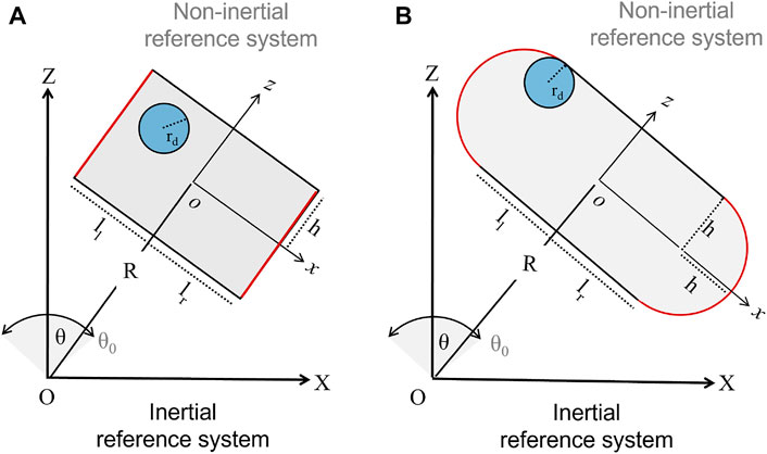
FIGURE 1. Sketches of two 2-dimensional ball-milling devices driven by harmonic pendular motion (X, Z) and (x, z) represent the inertial and non-inertial reference frames, respectively. Panel (A) illustrates a reactor with flat bases (in red) of width lf = ll + lr and height 2h, sustained by a mechanical arm of length R. ll and lr regulate the distance of the arm from the reactor center, and when the left and right sides of the reactor are different, ll ≠ lr, the system experiences an asymmetric forcing. The mechanical treatment is performed by a rigid disc of radius rd. The oscillatory motion is described by the angle θ, with maximal amplitude θ0 = π/12, and frequency ν = 18 Hz. Panel (B) shows a reactor characterized by curved bases of curvature radius h, width lc = ll + lr + 2h and height 2h.
The periodic angular motion of the reactor on the vertical plane follows θ = θ0 cos (ωt), where θ0 is the maximal angular amplitude and ω = 2πν gives the oscillation frequency. Two Cartesian reference frames can be used to reconstruct the reactor motion and the disc dynamics: the inertial system of coordinates (X, Z), which is centered at the lower end of the mechanical arm, and the non-inertial reference of coordinates (x, z), whose origin coincides with the geometrical center of the reactor, where the x axis is orthogonal to the mechanical arm. This non-inertial reference frame undergoes rigid displacement with the reactor.
The motion of each point in the system can be described and transformed from the non-inertial to the inertial coordinate system through the following systems of equations:
and
In the absence of external forces, the disc follows a rectilinear motion started by the impact with a reactor wall.
where
Whenever xb = (xb, zb)∉Ω (i.e., the distance of the disc from the reactor walls is smaller than rd), a collision occurs and the non-inertial component of the disc velocity normal to the impacted surface is instantaneously reversed, modulated by the restitution coefficient f. f ranges between 0 and 1, giving the inelastic and elastic limits, respectively. This mimics the effect of the powder undergoing a transformation inside the mechanochemical device on the collision efficiency. The term “collision” here identifies any event where the milling disc is at the reactor walls, including slipping phenomena.
As a whole, the dynamics of the milling body describes a forced-damped oscillator, where the impacts with the periodically moving reactor and friction at the walls feature the forcing and the damping contributions to the disc dynamics, respectively. In a sense, our problem features a complicated variant of the classical bouncing ball system (Tufillaro and Albano, 1986).
The duration of any given collision is limited to a single time step. Coherently with this aspect, the integration time step is set smaller than 10–5 s (we used ht = 10–7 s), which is also consistent with experimental data (Delogu et al., 1998) and the Hertzian theory of impacts (Love, 1944; Timoshenko and Goodier, 1970).
It is finally worth noticing that the acceleration experienced by the disc with the oscillation frequency at use is one order of magnitude larger than the gravitational acceleration, and this, together with the shortness of the disc’s mean free path, allows us to consider negligible the gravitational contribution to the disc motion.
3 Results and Discussion
3.1 Flat vs. Curved Bases
We first investigate the influence of the different shapes of the reactor lateral borders (either flat or curved) on the disc dynamics. To make the comparison between the two geometries as homogeneous as possible, we fixed the reactors’ height to 2h and adapted their width in order to get the same spatial domain Ωf = Ωc. As a reference, we assumed the values of typical devices with semicircular bases (wc + 2h = 57 mm and h = 9.4 mm), which are smaller than common Spex-mill apparatuses characterized by flat borders and already characterized in previous work (Caravati et al., 1999; Manai et al., 2002; Budroni et al., 2014). Equivalent areas of the spatial domains Ωf and Ωc are thus obtained via the relation wf = (2lc + πh)/2.
To facilitate the comparison of the two systems, we classified the possible behaviors in the parameter spaces spanning the restitution coefficient, f, and the disc radius, rd. From previous studies and preliminary simulations, these parameters remained the most relevant from the dynamical viewpoint, and a numerical benchmark on the effect of these parameters could be useful for practical purposes. The other parameters governing the mechanics of the system were fixed to typical values for these devices θ0 = π/12, ν = 18.6 Hz, R = 0.122 m. Simulations were run for 50 s and the resulting trajectories were analyzed from a dynamical viewpoint.
To get an integrated dynamical and energetic view, we also evaluated the average number of collisions on the reactor lateral borders (bases),
where md is the disc mass and
where
Figure 2 gives a global overview of the typical scenarios pertaining to the two systems, which clearly differ both in qualitative and quantitative terms.
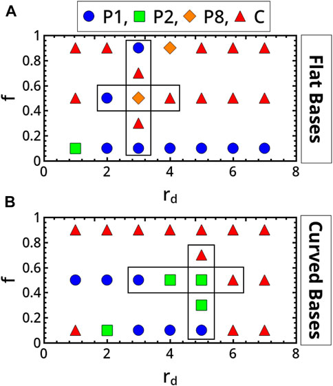
FIGURE 2. Classification in the parameter spaces spanning the restitution coefficient, f, and the disc radius, rd, of the main scenarios characterizing the milling body dynamics in flat-base (A) and curved-base (B) geometries. P1, P2, P8 and C identify period-1, period-2, period-8 and chaotic regimes, respectively.
Periodic regimes dominate the dynamics of the reactor with flat bases in inelastic conditions (low f). For this geometry, transitions from periodic to aperiodic behaviors can be observed by increasing the restitution coefficient (see for example, the back and forth scenario framed in Figure 2A for rd = 3 mm). This route to chaos (and back to regular periodicity) is illustrated in Figure 3, where we report the trajectories of the disc in the reactor along with the Fast Fourier Transforms (FFTs) of the vertical displacement of the disc in time (2). The transition is characterized by the alternation of periodic and aperiodic regimes which occurs in narrow windows of the control parameters (insignificant changes from the experimental viewpoint). Although a period-doubling scenario seems to regulate the transition, it was difficult to refine the whole sequence of bifurcations. Coarsely, by increasing f from 0.1 to 0.3, the system switches from a period-1 (P1) behavior (characterized by a main frequency twice the working frequency of the device) to a chaotic regime. The last regime shows the fingerprinting broad-band FFT profile of chaotic scenarios, with the same dominant frequency as the preceding periodic regime. We further analyzed the aperiodic dynamics by calculating the progressive divergence of two disc trajectories starting from infinitesimally distant initial positions, ‖δ0‖ ∼ 10–7 mm, with the formula ‖δ(t)‖ ≃‖δ0‖eλt for t ≫ 1. Although not calculated from the true phase-space, λ can give a rough estimation of the maximal Lyapunov exponent of the system (Strogatz, 1994; Kantz and Schreiber, 1997), whose positive values are a signature of chaotic regimes. Approaching chaos, λ goes from small negative values to positive values as reported in Figure 5A.
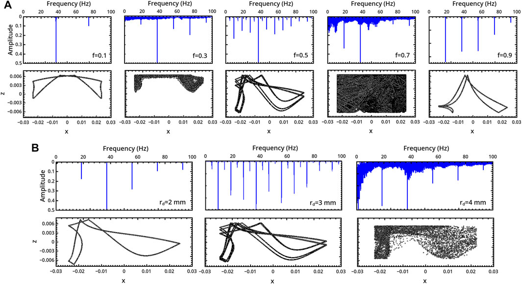
FIGURE 3. Characterization of the milling body dynamics in a flat-base geometry as a function of (A) the restitution coefficient f (rd = 3 mm) and (B) the milling disc radius rd (f = 0.5). For each regime, we report the trajectory (bottom) and the FFT of the related series describing the vertical displacement of the milling disc in time (top).
In the inelastic range f ∈ (0.1, 0.3), the milling disc spends most of the time in the upper part of the reactor. The related trajectories show a symmetric pattern with respect to the central x = 0 axis in the periodic regime, which transmutes into an asymmetric shape in the chaotic one.
The system undergoes a bifurcation to period-8 (P8) dynamics by further increasing f to 0.5 (see the frequency-halving in the related FFT), which preludes a new chaotic regime at f = 0.7. Elastic conditions (f = 0.9) bring the system back to a P1 periodicity compatible with the forcing frequency.
The dynamics of the disc is also very sensitive to the disc radius, and a transition from periodicity to chaos can be observed when rd is increased from 2 to 4 mm (with f = 0.5). Here also a period-doubling scenario can be inferred, though not all progressive regimes were isolated.
The asymmetric patterns drawn by the disc motion within the spatial domain can be reflected with respect to the axis x = 0 by reversing the initial direction of the external angular forcing.
In the system with curved bases, aperiodic dynamics are found not only in the elastic domain but also for low values of f (see also Figure 2 of the Supplementary Material). Again, the system can evolve from periodicity to chaotic regimes following a period-doubling-like pathway when f or rd are varied as framed in Figure 2B, explicitly illustrated in Figure 4 and characterized by computing the exponent λ in Figure 5B.
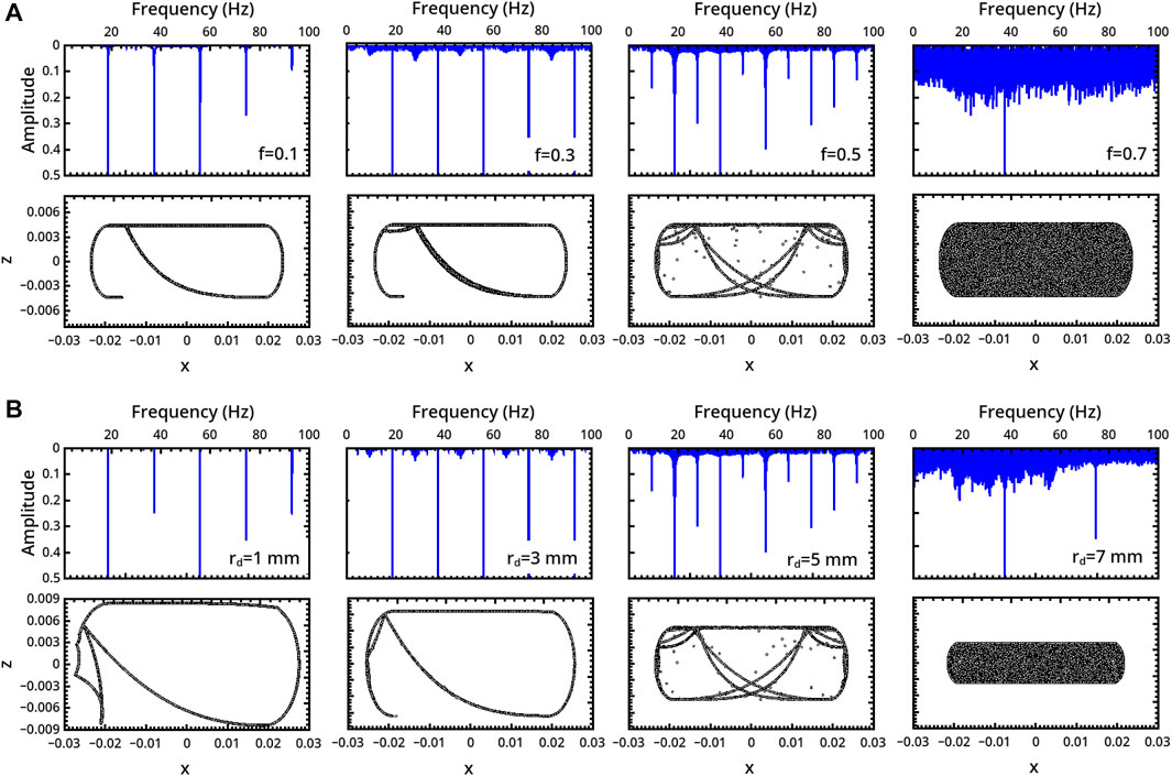
FIGURE 4. Characterization of the milling body dynamics in a curved-base geometry as a function of (A) the restitution coefficient f (rd = 5 mm) and (B) the milling disc radius rd (f = 0.5). For each regime, we report the trajectory (bottom) and the FFT of the time series describing the vertical displacement of the milling disc (top).
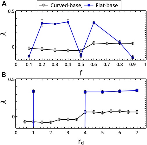
FIGURE 5. Exponential divergence, λ, characterizing milling body trajectories in the flat- and curved-base geometries when changing (A) the restitution coefficient f (rd = 5 mm) and (B) the milling disc radius rd (f = 0.5). λ was obtained through the formula ‖δ(t)‖ ≃‖δ0‖eλt, by calculating the distance ‖δ(t)‖ at any time t between two trajectories starting from infinitesimally distant conditions ‖δ0‖ → 0 (here ‖δ0‖ ∼ 10–7 mm) for t ≫ 1 (here after 50 s) (Kantz and Schreiber, 1997).
For both kinds of reactors, periodic regimes correspond to highly ordered trajectories where the milling disc explores a very restricted portion of the available area. However, while in flat-base reactors impacts take place in a few points of the reactor walls, curved-base geometries favor a displacement along the reactor borders dragged by the reactor motion.
This explains why the number of collisions experienced by the disc in the curved-base systems is, in general, much larger than that observed in flat-base reactors. In Figures 6A,B we report the dependence upon f and rd of the average number of collisions on the reactor bases, ⟨Collisions⟩ (in gray-black), and the relative energy, ⟨E⟩rel (in blue). In flat-base reactors (circles), ⟨Collisions⟩ shows a sharp drop-down as f is increased beyond the strongly inelastic condition 0.1 (rd = 5 mm), while a smoother decreasing trend pertains to curved-base reactors (Figure 6A). For both reactor types, ⟨Collisions⟩ is less sensitive to a variation of rd and the corresponding trends are essentially constant. The trends for ⟨E⟩rel of the two geometries are comparable both in qualitative and quantitative terms. The increasing trend with rd is described by Eq. 8 and is related to the disc mass, which increases correspondingly.
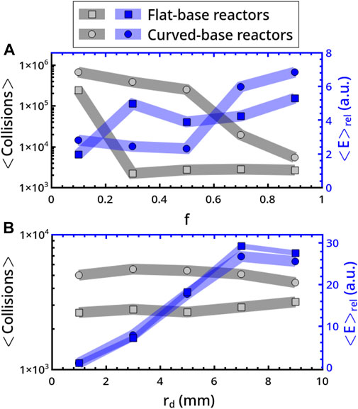
FIGURE 6. Analysis of the average number of collisions on the reactor bases, ⟨Collisions⟩ (in gray-black), and relative energy per collision, ⟨E⟩rel (in blue). ⟨E⟩rel was evaluated in relation to a disc of radius rd = 5 mm, to which we attributed unitary mass. ⟨Collisions⟩ and ⟨E⟩rel are characterized as a function of f (rd = 3 mm) in panel A and rd (f = 0.9) in panel B. Squares and circles refer to flat- and curved-base reactors, respectively.
In practical terms, curved-base reactors provide a more efficient mixing, showing wider regions of the parameter space where chaotic dynamics can be accessed and a larger number of collisions, which corresponds to a higher probability of inducing a transformation, but there is a negligible gain in energetic terms as compared to flat-base reactors.
3.2 Scaling the Reactor Size
The reactors with different shapes of the lateral borders show divergent dynamics even if the sizes of the milling body and the reactor, as well as all the other mechanical parameters, are the same. However, given the dependence of the dynamics of the two reactors on the size of the milling body, we checked whether systems with the same basis type and the same ratio of the reactor size to that of the milling body converge to analogous regimes. The rationale is that discs with an analogous free space to move, under the same mechanical forcing, could give a similar dynamical response. If this is the case, the dimensionless ratio
We thus explored separately the dynamics of symmetrically forced reactors with either flat or curved bases, keeping fixed Q. Specifically, we compared the behaviors of systems where a constant Q is obtained by varying the reactor dimensions (i) without keeping the reactor aspect ratio (i.e., changing at will the width and the height of the reactor with the length of the mechanical arm, R, fixed) (case 1), (ii) preserving the aspect ratio of the reactor by scaling its dimensions by the same factor (with R fixed) (case 2), and (iii) scaling the whole system proportionally, including the length of the mechanical arm (case 3).
We first comment on the general case 1. Figure 7A shows a representative parallel between the dynamical regimes of two systems with flat bases, one being 2.25 times larger than the other, including the disc area. In particular, there are superimposed the FFTs of the temporal series describing the disc displacement along the vertical axis, z. An analogous comparison is reported for reactors with curved bases in Figure 7D (related trajectories can be found in Figure 3 of the Supplementary Material). In both cases, preserving Q does not translate into analogous regimes. In the example with flat base reactors, the regular periodicity characterizing the “small” reactor changes into an aperiodic scenario in the scaled reactor. Viceversa, a transition from strongly aperiodic to period-1 behavior is observed in the curved-base system. In general, we found that the discrepancy between the dynamics of reference and scaled systems holds from both qualitative and quantitative viewpoints for different combinations of f and rd (becoming much more prominent when approaching elastic conditions, see Figure 2 of the Supplementary Material), and also by increasing the horizontal instead of the vertical dimension.
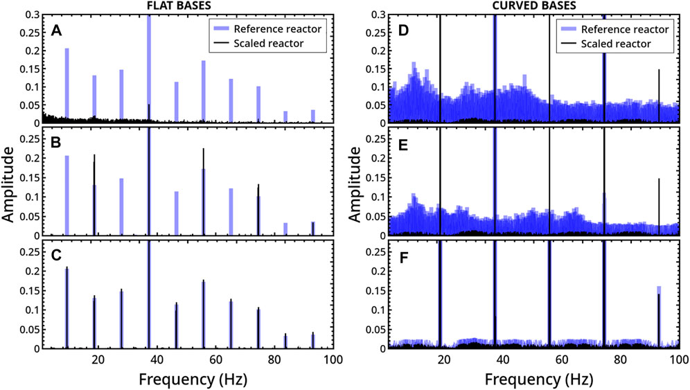
FIGURE 7. Comparison between the milling disc dynamics obtained by changing the reactor size with the milling disc radius in flat-base (left) and curved-base (right) geometries, keeping fixed the ratio
A similar comparison between systems where the reactor dimensions are scaled proportionally while maintaining the aspect ratio does not indicate any dynamical matching (see an example in Figures 7B,E), unless the mechanical arm is also scaled by the same scale factor, which is shown in Figures 7C,F. In this last case, the trajectory described by the disc within the two scaled reactors follows the same scaled path (see Figure 4 of Supplementary Material) and, as a consequence, the Fourier analysis leads to overlapping results.
In Figure 8 we can observe that both in flat- and curved-base reactors, the average number of collisions on the bases ⟨Collisions⟩ is maximal for the reference reactor (case 3 coincides with this). By contrast, the average energy per collision will be larger in scaled systems not only because of the increment in the mass of the milling body but also because of an increment in the mean squared velocity of the disc, ⟨v2⟩. In particular, in flat reactors, apart from case 1, ⟨v2⟩ is larger in the scaled reactors than in the smaller reference system, with
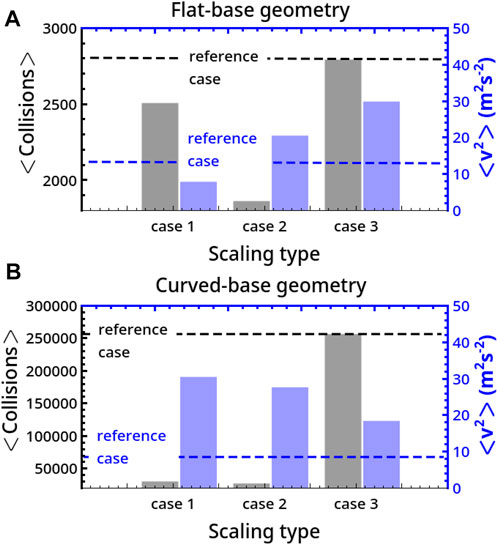
FIGURE 8. Comparison of the average number of collisions on the basis, ⟨Collisions⟩, and mean squared velocity per collision, ⟨v2⟩, for different scaling (cases 1, 2, and 3) of the system size. Panel A and B describe results for flat- and curved-base geometries.
Another way to relate the dynamics of the milling body to the spatial domain available relies on simple geometrical arguments. Since the conditions for collisions are based on the distance rd of the disc center from the borders, when rd increases by, ϵ, collision conditions remain unaltered if the dimensions of the reactor are increased by the same quantity ϵ at each side in the flat-base and if the reactor half-height increases to h + ϵ in the curved-base systems. In other words, the dynamics of a disc with a radius
in flat-base geometry, and to
in geometries with curved bases. These equivalence criteria, allowing to adapt the system size to a change in the disc radius in order to get the same dynamics, are applied to the representative systems shown in Figure 9. There are reported small portions of the spatial trajectories of a milling disc moving in a flat-base symmetrically-forced reactor when rd changes from 1 mm (panel (a)) to 4 mm (panel (b)) and, consequently, Ωf = 20, ×, 40 mm is varied to Ωf = 26 × 46 mm (f = 0.5). The resulting dynamics are identical and show overlapping FFTs of the temporal x-displacement in Figure 9C. Analogous results were also found for curved-base reactors (see Figure 5 of the Supplementary Material).
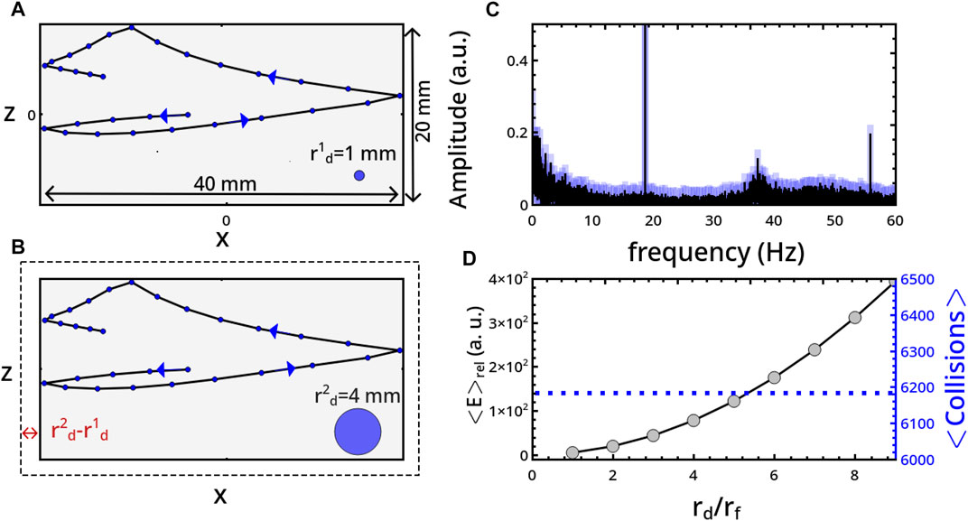
FIGURE 9. Comparison between the milling disc dynamics obtained with rd = 1 mm (A) and rd = 4 mm (B) (i.e., ϵ = 3 mm), by adapting the spatial domain from Ωf = 20, ×, 40 mm to Ωf = 26 × 46 mm, according to Eqs 9, 10. f is fixed to 0.5. (C) Comparison between the FFTs of the x-displacement of the milling disc in time. (D) Average number of collisions on the bases, ⟨Collisions⟩, and average relative energy per collision, ⟨E⟩rel, with respect to the reference energy of a milling disc with radius rf = 1 mm.
If, in this way, the dynamical regime of the milling body is preserved, things vary from the energetic viewpoint due to the increase of the disc mass. Assuming a constant density of the disc and verified that the velocity distribution does not change while adapting the reactor size, the average energy per collision will only depend upon rd. In particular, ⟨E⟩rel, measuring the average energy per collision of a disc with radius rd with respect to that of a reference radius rf, follows
3.3 Symmetrical vs. Asymmetrical Forcing
We finally explored the impact of an asymmetric forcing imposed on the disc when the mechanical arm is placed at different distances from the reactor center, for instance, decreasing ll in favor of lr. The results for the two reactor geometries under consideration are summarized in Figure 10, where we report different dynamics observed by progressively decreasing ll (increasing lr) by steps of 5 mm from the centered allocation, which is ll = 26 mm (the case f = 0.5 and rd = 3 mm is considered).
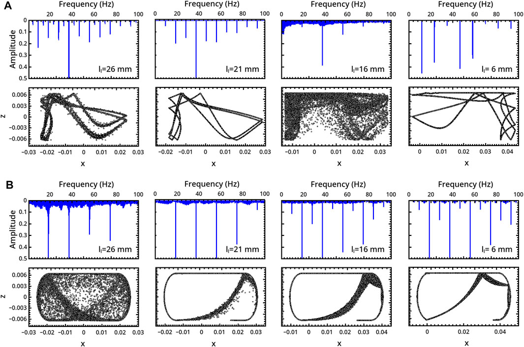
FIGURE 10. Characterization of the milling body dynamics in (A) flat- and (B) curved-base geometries as a function of the mechanical arm location, ll. For each regime, we report the trajectory (bottom) and the FFT of the time series describing the vertical displacement of the milling disc (top).
In the flat-base system (Figure 10A), the system firstly undergoes a transition from a P8 (ll = 26 mm) to a P4 (ll = 21 mm) periodicity, and then a chaotic regime for ll = 16 mm occurs. Pushing further the geometrical asymmetry (ll = 6 mm) the dynamics recovers a P1 behavior characterized by a main frequency which is half of the device forcing frequency.
In reactors with curved bases (Figure 10B), the asymmetry shows a “simplifying” effect in dynamical terms, inducing a transition from an initial chaotic regime for the centered arm to different kinds of periodicity: P1 (with the same devise working frequency) for ll = 21 mm, P2 for ll = 16 mm and P4 for ll = 6 mm.
As shown in Figure 11, in both geometries the average number of collisions on the bases is not substantially affected by the asymmetric position of the mechanical arm. However, the two reactor types follow opposite trends in energetic terms, with the average relative energy of the collisions decreasing with the asymmetry of the forcing (i.e., decreasing ll) in flat-base reactors. The opposite is true in curved-base reactors. A correlation between the typology of the dynamical regimes and collision energy can hardly be established. We can just point out that chaotic regimes correspond to a decrement of ⟨E⟩rel.
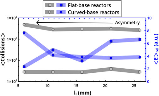
FIGURE 11. Dependence of ⟨Collisions⟩ and ⟨E⟩rel on the forcing asymmetry as controlled by the mechanical arm location, ll.
4 Concluding Remarks
The geometry of the reactor used in ball-milling approaches can profoundly impact the outcome of a mechanical process by affecting the dynamics of the milling body, which rules the powder dragging, mixing, and concretely transfers the mechanical energy to induce physico-chemical transformations at collision with other milling bodies or with the reactor walls.
In this work we have focused our attention on the dynamics of one milling body driven by a harmonic pendular force within two different geometries, namely reactors with flat and curved bases, which are among the most common devices in use. By using a 2-dimensional description of these systems, we have probed the dynamical response of a milling body to the variation of relevant parameters such as the milling body size and the restitution coefficient. These parameters present experimental interest and turn out to critically control the transition from periodic to chaotic behaviors in both the geometries considered, following period-doubling-like routes. Parametric regions where the systems show chaotic behaviors and, hence, potentially more efficient mixing, are observed in curved-base reactors, where aperiodic dynamics dominate in the presence of nearly elastic conditions and are also found in inelastic conditions. Although the energetic profiles of the two geometries as a function of the control parameters considered are essentially overlapping, curved-base reactors are characterized by a larger number of collisions, which could translate into a higher probability of inducing a transformation. A direct correspondence between the dynamic type and the energetics of the system cannot be established. In both systems, the number of collisions is larger in periodic inelastic conditions as these favor the slipping of the milling body on the reactor walls.
A more general criterion for controlling the dynamics within the systems relies on a suitably small change in the relative size of the reactor and that of the milling body. Here we identified two possible ways to maintain a given dynamic when the milling body size is varied: i) scaling the reactor size, including the length of the mechanical arm, of the same factor of the milling body size variation; ii) augmenting the reactor width and height by the same increment (or decrement) of the milling body radius. In both cases, a desired regime can be modulated in intensity (i.e., the collision energy can be either increased or decreased) while maintaining unaltered the dynamical features.
An asymmetric force on the milling body, which can be imposed by changing the position of the mechanical arm with respect to the reactor center, can also play a critical role in controlling the transition from periodic to chaotic regimes.
Data Availability Statement
The raw data supporting the conclusion of this article will be made available by the authors without undue reservation.
Author Contributions
FD and MB conceived this work. AP, MC, and MB ran simulations and analyzed and interpreted data. All the authors contributed to the editing of the manuscript.
Funding
This work was supported by Attrazione e mobilità dei ricercatori, Linea 2 (Attrazione dei Ricercatori), and funding by University of Sassari (Fondo di Ateneo per la ricerca 2020). MC performed her activity within the framework of the International PhD in Innovation Sciences and Technologies at the Università degli Studi di Cagliari, Italy.
Conflict of Interest
The authors declare that the research was conducted in the absence of any commercial or financial relationships that could be construed as a potential conflict of interest.
Publisher’s Note
All claims expressed in this article are solely those of the authors and do not necessarily represent those of their affiliated organizations, or those of the publisher, the editors, and the reviewers. Any product that may be evaluated in this article, or claim that may be made by its manufacturer, is not guaranteed or endorsed by the publisher.
Acknowledgments
MB gratefully acknowledges funding from Programma Operativo Nazionale (PON) Ricerca e Innovazione 2014–2020, Asse I Capitale Umano, Azione I.2 A.I.M.
Supplementary Material
The Supplementary Material for this article can be found online at: https://www.frontiersin.org/articles/10.3389/fchem.2022.915217/full#supplementary-material
Footnotes
1https://www.cost.eu/stories/mechanochemistry-pushes-more-sustainable-processes.
2While the horizontal component of the disc displacement is essentially Imposed by the working frequency of the devise, the vertical Displacement confers emergent features to the global dynamics (see Figure 1 of the Supplementary Material).
References
Abdellaoui, M., and Gaffet, E. (1995). The Physics of Mechanical Alloying in a Planetary Ball Mill: Mathematical Treatment. Acta Metallurgica Materialia 43, 1087–1098. doi:10.1016/0956-7151(95)92625-7
Aref, H., Blake, J. R., Budišić, M., Cardoso, S. S. S., Cartwright, J. H. E., Clercx, H. J. H., et al. (2017). Frontiers of chaotic advection. Rev. Mod. Phys. 89, 025007. doi:10.1103/RevModPhys.89.025007
Avvakumov, E. G. (1986). Mechanical Methods for Activation of Chemical Processes. Novosibirsk: Nauka.
Balaz, P., Achimovicova, M., Balaz, M., Billik, P., Cherkezova-Zheleva, Z., Manuel Criado, J., et al. (2013). Chem. Soc. Rev. 42, 7571.
Boldyrev, V. V. (1983). Experimental Methods in the Mechanochemistry of Solid Inorganic Materials. Novosibirsk: Nauka.
Boldyreva, E. (2013). Mechanochemistry of Inorganic and Organic Systems: what Is Similar, what Is Different? Chem. Soc. Rev. 42, 7719. doi:10.1039/c3cs60052a
Boschetto, A., Bellusci, M., La Barbera, A., Padella, F., and Veniali, F. (2013). Kinematic Observations and Energy Modeling of a Zoz Simoloyer High-Energy Ball Milling Device. Int. J. Adv. Manuf. Technol. 69, 2423–2435. doi:10.1007/s00170-013-5201-9
Broseghini, M., Gelisio, L., D’Incau, M., Azanza Ricardo, C. L., Pugno, N. M., and Scardi, P. (2016). Modeling of the Planetary Ball-Milling Process: The Case Study of Ceramic Powders. J. Eur. Ceram. Soc. 36, 2205–2212. doi:10.1016/j.jeurceramsoc.2015.09.032
Budroni, M. A., Baronchelli, A., and Pastor-Satorras, R. (2017). Phys. Rev. E 95 (5), 052311. doi:10.1103/physreve.95.052311
Budroni, M. A., Pilosu, V., Delogu, F., and Rustici, M. (2014). Multifractal Properties of Ball Milling Dynamics. CHAOS 24 (2), 023117. doi:10.1063/1.4875259
Burgio, N., Iasonna, A., Magini, M., Martelli, S., Padella, F., Burgio, N., et al. (1991). Mechanical Alloying of the Fe−Zr System. Correlation between Input Energy and End Products. Il Nuovo Cimento D. 13, 459–476. doi:10.1007/bf02452130
Butyagin, P. Y. (1971). Kinetics and Nature of Mechanochemical Reactions. Usp. Khim. 40, 1935. doi:10.1070/rc1971v040n11abeh001982
Caravati, C., Delogu, F., Cocco, G., and Rustici, M. (1999). Hyperchaotic Qualities of the Ball Motion in a Ball Milling Device. CHAOS 9, 219–226. doi:10.1063/1.166393
Carta, M., Colacino, E., Delogu, F., and Porcheddu, A. (2020). Kinetics of Mechanochemical Transformations. Phys. Chem. Chem. Phys. 22, 14489–14502. doi:10.1039/d0cp01658f
Carta, M., Delogu, F., and Porcheddu, A. (2021). A Phenomenological Kinetic Equation for Mechanochemical Reactions Involving Highly Deformable Molecular Solids. Phys. Chem. Chem. Phys. 23, 14178–14194. doi:10.1039/d1cp01361k
Cleary, P. W., Sinnott, M., and Morrison, R. (2006). Analysis of Stirred Mill Performance Using DEM Simulation: Part 2 - Coherent Flow Structures, Liner Stress and Wear, Mixing and Transport. Miner. Eng. 19, 1551–1572. doi:10.1016/j.mineng.2006.08.013
Concas, A., Lai, N., Pisu, M., and Cao, G. (2006). Modelling of Comminution Processes in Spex Mixer/Mill. Chem. Eng. Sci. 61, 3746–3760. doi:10.1016/j.ces.2006.01.007
Delogu, F., Monagheddu, M., Mulas, G., Schiffini, L., and Cocco, G. (2000). Int. J. Non-Equilib. Process. 11, 235.
Delogu, F., Mulas, G., Monagheddu, M., Schiffini, L., and Cocco, G. (1998). Int. J. Non-Eq. Proc. (IJNEP) 11, 235.
Do, J.-L., and Friščić, T. (2017). Mechanochemistry: A Force of Synthesis. ACS Cent. Sci. 3, 13–19. doi:10.1021/acscentsci.6b00277
Feng, Y. T., Han, K., and Owen, D. R. J. (2004). Discrete Element Simulation of the Dynamics of High Energy Planetary Ball Milling Processes. Mater. Sci. Eng. A 375-377, 815–819. doi:10.1016/j.msea.2003.10.162
Friscic, T., Mottillo, C., and Titi, H. M. (2020). Mechanochemistry for Synthesis. Angew. Chem. Int. Ed. 59, 1018. doi:10.1002/anie.201906755
Friscic, T. (2012). Supramolecular Concepts and New Techniques in Mechanochemistry: Cocrystals, Cages, Rotaxanes, Open Metal–Organic Frameworks. Chem. Soc. Rev. 41, 3493. doi:10.1039/C2CS15332G
Galant, O., Cerfeda, G., McCalmont, A. S., James, S. L., Porcheddu, A., Delogu, F., et al. (2022). ACS Sust. Chem. Eng. 10, 1430–1439.
Gil-González, E., Rodríguez-Laguna, M. d. R., Sánchez-Jiménez, P. E., Perejón, A., and Pérez-Maqueda, L. A. (2021). Unveiling Mechanochemistry: Kinematic-Kinetic Approach for the Prediction of Mechanically Induced Reactions. J. Alloys Compd. 866, 158925. doi:10.1016/j.jallcom.2021.158925
James, S. L., Adams, C. J., Bolm, C., Braga, D., Collier, P., Friščić, T., et al. (2012). Mechanochemistry: Opportunities for New and Cleaner Synthesis. Chem. Soc. Rev. 41, 413–447. doi:10.1039/c1cs15171a
Kantz, H., and Schreiber, T. (1997). Nonlinear Time Series Analysis. Cambridge: Cambridge University Press.
King, G. (1998). Towards a Science of Mixing. Phys. World 11 (11), 23–24. doi:10.1088/2058-7058/11/11/24
Magini, M., Iasonna, A., and Padella, F. (1996). Ball Milling: an Experimental Support to the Energy Transfer Evaluated by the Collision Model. Scr. Mater. 34, 139. doi:10.1016/1359-6462(95)00465-3
Manai, G., Delogu, F., and Rustici, M. (2002). Onset of Chaotic Dynamics in a Ball Mill: Attractors Merging and Crisis Induced Intermittency. CHAOS 12, 601–609. doi:10.1063/1.1484016
Michalchuck, A. A. L., Boldyreva, E. V., Belenguer, A. M., Emmerling, F., and Boldyrev, V. V. (2020). Front. Chem. 9, 685789.
Porcheddu, A., Colacino, E., De Luca, L., and Delogu, F. (2020). Metal-Mediated and Metal-Catalyzed Reactions under Mechanochemical Conditions. ACS Catal. 10, 8344–8394. doi:10.1021/acscatal.0c00142
Rightmire, N. R., and Hanusa, T. P. (2016). Advances in Organometallic Synthesis with Mechanochemical Methods. Dalton Trans. 45, 2352–2362. doi:10.1039/c5dt03866a
Rustici, M., Mulas, G., and Cocco, G. (1996). Detecting Chaotic Attractors in a Ball Milling Process. Msf 225-227, 243–248. doi:10.4028/www.scientific.net/msf.225-227.243
Sinnott, M., Cleary, P. W., and Morrison, R. (2006). Analysis of Stirred Mill Performance Using DEM Simulation: Part 1- Media Motion, Energy Consumption and Collisional Environment. Miner. Eng. 19, 1537–1550. doi:10.1016/j.mineng.2006.08.012
Strogatz, S. H. (1994). Nonlinear Dynamics and Chaos: With Applications to Physics, Biology, Chemistry, and Engineering. Boulder, Colorado, USA: Westview Press.
Takacs, L. (2013). The Historical Development of Mechanochemistry. Chem. Soc. Rev. 2013. doi:10.1039/C2CS35442J
Tan, D., and García, F. (2019). Main Group Mechanochemistry: from Curiosity to Established Protocols. Chem. Soc. Rev. 48, 2274–2292. doi:10.1039/c7cs00813a
Thiessen, P. A., Meyer, K., and Heinicke, G. (1967). Grundlagen der Tribochemie. Berlin: Akademie Verlag.
Tufillaro, N. B., and Albano, A. M. (1986). Chaotic Dynamics of a Bouncing Ball. Am. J. Phys. 54, 939–944. doi:10.1119/1.14796
Wang, G.-W. (2013). Mechanochemical Organic Synthesis. Chem. Soc. Rev. 42, 7668. doi:10.1039/c3cs35526h
Watanabe, R., Hashimoto, H., and Geun Lee, G. (1995). Mater. Trans. JIM 36, 2. doi:10.2320/matertrans1989.36.102
Keywords: transition to chaos, forced-damped oscillators, modeling of mechanochemical systems, mechanochemistry, ball-mill grinding
Citation: Polo A, Carta M, Delogu F, Rustici M and Budroni MA (2022) Controlling Nonlinear Dynamics of Milling Bodies in Mechanochemical Devices Driven by Pendular Forcing. Front. Chem. 10:915217. doi: 10.3389/fchem.2022.915217
Received: 07 April 2022; Accepted: 20 June 2022;
Published: 05 August 2022.
Edited by:
Rabih Sultan, American University of Beirut, LebanonReviewed by:
Angelo Facchini, IMT School for Advanced Studies Lucca, ItalyMarco Masia, University of Vienna, Austria
Copyright © 2022 Polo, Carta, Delogu, Rustici and Budroni. This is an open-access article distributed under the terms of the Creative Commons Attribution License (CC BY). The use, distribution or reproduction in other forums is permitted, provided the original author(s) and the copyright owner(s) are credited and that the original publication in this journal is cited, in accordance with accepted academic practice. No use, distribution or reproduction is permitted which does not comply with these terms.
*Correspondence: M. A. Budroni, bWFidWRyb25pQHVuaXNzLml0