 Xiaojian Feng
 Zixuan Zhang
 Chao Han
 Zhangxing He
94% of researchers rate our articles as excellent or good
Learn more about the work of our research integrity team to safeguard the quality of each article we publish.
Find out more
ORIGINAL RESEARCH article
Front. Chem., 24 June 2021
Sec. Electrochemistry
Volume 9 - 2021 | https://doi.org/10.3389/fchem.2021.688634
This article is part of the Research TopicDesign, Synthesis, and Modification of Metal Oxides for Energy StorageView all 12 articles
In this work, nanosized P-doped SnO2 (SnO2-P) was prepared by a sol–gel method as a catalyst for the V3+/V2+ redox reaction in vanadium redox flow battery. Compared with SnO2, the electrochemical performance of SnO2-P is significantly improved. This is because P doping provides more active sites and shows greatly improved electrical conductivity, thereby increasing the electron transfer rate. As a result, SnO2-P shows better catalytic performance than SnO2. The SnO2-P modified cell is designed, and it exhibits an increase of 47.2 mA h in discharge capacity and 8.7% in energy efficiency compared with the pristine cell at 150 mA cm−2. These increases indicate that the modified cell has a higher electrolyte utilization rate. This study shows that SnO2-P is a new and efficient catalyst for vanadium redox flow battery.
The excessive use of fossil fuels has resulted in an increasing depletion of energy resources and significant damage to the environment (Cheng et al., 2020; Huang et al., 2020; Liu et al., 2020; Li et al., 2021; Wang et al., 2021). Hence, the development of new energy sources for environmental protection is a critical issue (Wang T. et al., 2020; Chuanchang et al., 2020; Fang et al., 2020; He et al., 2020; Yang et al., 2020; Liu et al., 2021; Nie et al., 2021). These include green and clean energy sources, such as solar energy and tidal energy. Nevertheless, these energy sources have the disadvantage of poor stability and weak continuity (Wu et al., 2021; Zhang and Sun, 2021). Therefore, researchers must solve these problems by developing high-performance energy storage technology.
Skyllas-Kazacos et al. (1986) established the concept of vanadium redox flow battery (VRFB), which has advantages that include flexible design, environmental friendliness, and high reliability. VRFB currently represents a promising choice for energy storage challenges (Jelyani et al., 2016; Zhang et al., 2018; Jiang et al., 2021a; Ye et al., 2021). VO2+/VO2+ and V3+/V2+ solutions are designed as the positive and negative active species for VRFB, respectively (Jiang et al., 2021b; Lv et al., 2021). A H+ exchange membrane is placed in the middle to form a closed loop. The electrode is an important component of VRFB and is where the redox reaction takes place. Nowadays, carbon materials including graphite felt (GF), carbon cloth, and carbon felt are the main electrode materials for this technology. These materials have the advantages of large specific surface area, low cost, and good stability. However, their poor surface hydrophilicity and low electrochemical activity limit their application. Therefore, carbon-based materials need to be modified before usage.
The modification treatments are generally divided into two methods: direct activation and the introduction of catalysts. Direct activation, including acid and heat treatments, can improve the wettability of the material. The introduction of catalysts on the surface mainly includes metals, metal oxides, and carbon-based materials. The metals used include Ni, Pt (Tseng et al., 2013), and Ir (Wang and Wang, 2007). For example, González et al. (2011) studied the application of nano-Bi-modified GF for VRFB. The modified electrode showed excellent electrochemical performance and outstanding reversibility. This is due to the nano-Bi providing more active sites, which in turn promote the redox reaction. The typical metal oxides used include CeO2 (Zhou et al., 2014), Mn3O4 (Di Blasi et al., 2017), and TiO2 (Vázquez-Galván et al., 2019). For instance, Wu et al. (2014) prepared SbO2 modified GF by electrodeposition. Due to the excellent catalytic activity and stability of SbO2, the electrochemical performance of the cell was effectively improved. The carbon-based materials include carbon nanosheets (Wang J. et al., 2020), carbon nanotubes (Li et al., 2020), and carbon nanofibers (Wei et al., 2016). For example, Aziz et al. (2020) synthesized nitrogen-doped carbon nanorods (NCNR) via electrospinning. Compared with the original carbon felt, the carbon felt with NCNR had better rate capability. This was attributed to the significantly increased vanadium ion contact area and the accelerated electron transfer process.
SnO2 is a low-cost metal oxide with excellent electrochemical activity and is widely used in electrochemical fields (Liu et al., 2016; Ahmed et al., 2017; Chen et al., 2019; Zhang et al., 2020). Mehboob et al. (2018) reported that SnO2-deposited carbon felt had higher discharge capacity and cycle stability in VRFB. SnO2 was shown to have excellent electrocatalytic performance and was an efficient catalyst. However, the conductivity of SnO2 is poor, which limits its application. In order to solve this problem, P-doped SnO2 (SnO2-P) is prepared by a sol–gel method in this work. SnO2-P has better catalytic performance than SnO2. This is because SnO2-P combines the advantages of SnO2 and P. SnO2 mainly provides catalytic active sites, while the introduction of P improves the conductivity of the material. The electrochemical activity of the V3+/V2+ redox reaction in a VRFB is promoted. In summary, this work provides a potential method for improving the performance of VRFB using nanosized SnO2-P.
In this study, samples were prepared by a sol–gel method. SnCl2·2H2O (2.247 g) was weighed and dissolved into 20 ml of absolute ethanol. It was then also oscillated by ultrasound for 30 min and magnetically agitated at 65°C for 2 h in a water bath. When gradually forming the gel, 0.047 g of H3PO4 (85 wt.%) solution was added to SnO2 gel. The gel gradually turned pale yellow. The magnet was removed and sealed for aging for 24 h. The two samples were then dried at 80°C for 24 h in the vacuum drying oven and heated at 600°C for 2 h in a muffle furnace. The sample was named SnO2-P. Similarly, with SnCl2·2H2O particles as the tin source and phosphoric acid as the source of phosphorus doping, the solution was magnetically agitated to gradually make the gel and then to obtain SnO2.
To study the crystal phase of the samples, X-ray diffraction (XRD) was completed using a D/MAX2500PC instrument. Scanning electron microscopy (SEM, JSM-IT100) was used to analyze the morphology of the samples. The element composition and chemical state of the samples were studied by X-ray photoelectron spectroscopy (XPS) via a K-Alpha 1063 instrument (Thermo Fisher Scientific, United Kingdom).
The electrochemical measurements using an electrochemical workstation (CHI660E; Shanghai Chenghua Instruments) were performed by a system consisting of three electrodes. A glassy carbon electrode acted as the working electrode, a platinum electrode served as the counter electrode, and a saturated calomel electrode as the reference electrode. The 1 mg SnO2 sample was evenly mixed with 9 mg of acetylene black (AB), and the mixture was dispersed in N, N-dimethylformamide (DMF) under ultrasonic dispersion for 3 h. Finally, 20 μl dispersion completely fell on the electrode and it was then dried for 4 h at room temperature. The electrochemical measurements based on cyclic voltammetry (CV) and electrochemical impedance spectroscopy (EIS) were performed in a negative electrolyte of 1.6 M V3+ + 3.0 M H2SO4. The EIS test was performed in a constant potential mode. The frequency range was 10−1–106 Hz.
In a voltage window of 0.7–1.65 V, the charge–discharge performance of the cell was studied using a battery test device (CT 2001A; Wuhan Land, China). The 3 × 3 cm2 of GF, purchased from Jinglong Carbon Graphite Plant, was pretreated with ethanol for 30 min under the action of ultrasound. The ion exchange membrane (Nepem-1110) was pretreated by immersing in a 3.0 M H2SO4 solution over 24 h. This was used as the separation membrane for the positive and negative cells. SnO2-P (3 mg) was dispersed in 10 ml of DMF. The GF was then soaked in it for 3 h by ultrasonic dispersion to allow SnO2-P to be adsorbed on the GF. The modified GF was placed in the oven for drying. This process was used to prepare the modified GF, which was used as the negative electrode of the modified cell. For comparison, a pristine GF was used as the two electrodes of the pristine cell. To completely absorb the electrolyte, the pristine and modified GFs were soaked in the electrolyte of 0.8 M V3+ + 0.8 M VO2+ + 3.0 M H2SO4 for 12 h, respectively. The cell began a charge–discharge test three times to achieve an equilibrium of the positive and negative electrolytes at 10 mA cm−2.
Figure 1 shows the XRD patterns of SnO2 and SnO2-P. By comparing these XRD patterns, the qualitative identification of the phase composition and structure can be achieved. The characteristic peaks of SnO2 and SnO2-P are in the same place. The peak widths of the samples are close to each other. It can be seen that the observed peak corresponds to the standard value of SnO2 (JCPDC No. 01-070-4175). The structure of SnO2 corresponds to the tetragonal cassiterite type. There are no impurity characteristic peaks, indicating that no new phase is introduced by doping.
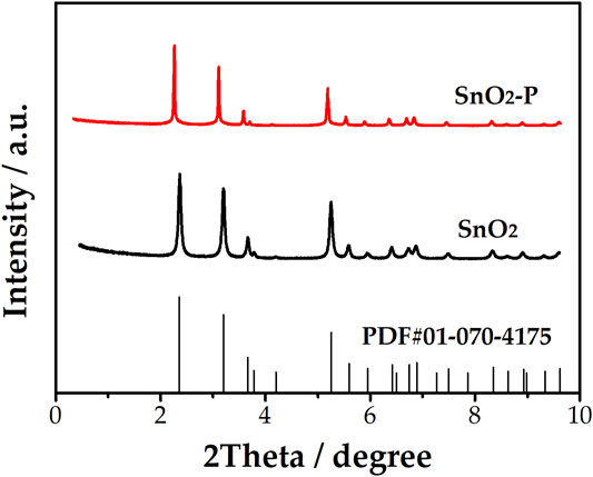
FIGURE 1. XRD patterns of SnO2 and SnO2-P.
Figure 2 shows the SEM characterization of SnO2 (Figures 2A,B) and SnO2-P (Figures 2C,D). The morphology of the SnO2 and SnO2-P nanoparticles was studied by SEM. The results show that the nanoparticles are uniformly dispersed without obvious agglomeration. There is no significant difference in the size of the nanoparticles after P doping, and the diameter of the two particles is between 200 and 300 nm. The aforementioned results show that P doping has no obvious effect on the morphology.
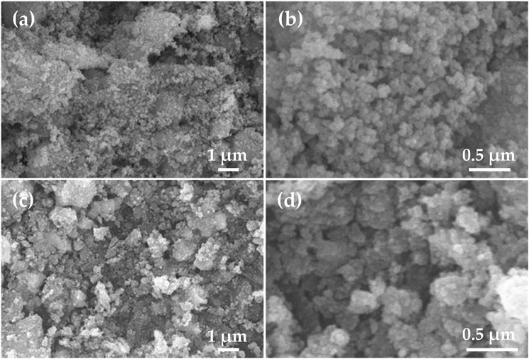
FIGURE 2. SEM images of SnO2(A,B) and SnO2-P (C,D).
Figure 3A shows that Sn, O, P, and C correspond to the binding energy table of elements. Combined with the previous XRD analysis, it can be confirmed that P has been doped into the SnO2 lattice. In Figure 3B, the O 1s peak can be convoluted into two peaks at 531.0 and 532.1 eV, representing the Sn-O and C-O bonds, respectively (Powell et al., 2018). Figure 3C indicates that there are two peaks at 495.6 and 487.1 eV corresponding to Sn 3d3/2 and Sn 3d5/2, respectively. Figure 3D indicates that there are two peaks at 134.1 and 139.2 eV, corresponding to the P 2p peak, thereby confirming the existence of P in the treated sample. The peaks of P at 134.1 and 139.2 eV represent the P-C and P-O bonds, respectively. The results show that Sn is only present in P5+, which replaces Sn ions to generate extra valence electrons, resulting in a decrease in resistivity.
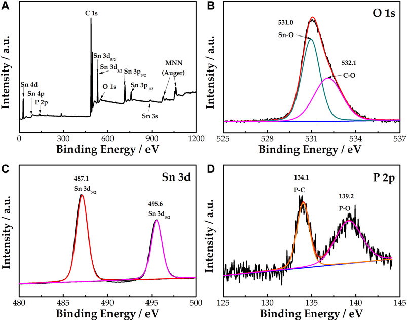
FIGURE 3. XPS survey spectrum of SnO2-P (A). High-resolution XPS spectra of O 1s (B), Sn 3d (C), and P 2p (D) for SnO2-P.
The catalysis of AB, SnO2, and SnO2-P for the activity of the V3+/V2+ redox reaction was evaluated by CV measurements. The CV curves of the three samples are shown in Figure 4. All the electrodes have a higher reduction peak current than an oxidation peak current. This is due to the electrolyte containing more V3+ than V2+. The peak current of SnO2 (oxidation: 1.66 mA, reduction: 2.96 mA) is higher than that of AB (oxidation: 1.5 mA, reduction: 2.38 mA). This is due to SnO2 possessing good catalytic activity and providing active sites for the electrode reaction. Compared with that of SnO2, the peak current of SnO2-P is higher. This indicates that P doping improves the electrochemical properties of SnO2 for the redox reaction of the V3+/V2+ couple.
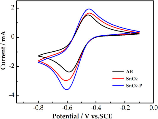
FIGURE 4. CV curves for AB, SnO2, and SnO2-P carried out in 1.6 M V3+ + 3.0 M H2SO4 electrolyte at a scan rate of 10 mV s−1.
The CV test was carried out at different scan rates for further studying the influence of different electrodes on the mass transfer rate of the reactants. As presented in Figures 5A–C, for the three electrodes, the peak shape of all the CV curves remains symmetrical with an increasing scan rate. This proves that the electrochemical stability is good. In addition, the peak current increases as the scan rate increases. The oxidation and reduction peak potentials shift to the right and left, respectively. Figure 5D shows the relationship between the square root of the scan rate and the redox peak current. The peak current is obviously proportional to the square root of the scan rate for all samples. This proves that the redox reaction is under the control of the diffusion process. The mass transfer rate improves with an increase in the linear slope. The slope of SnO2 is larger than that of AB because SnO2 can provide more active sites. Simultaneously, the linear slope of SnO2-P is larger than that of SnO2. This indicates that P doping is beneficial to the migration of active substances.
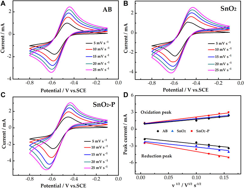
FIGURE 5. CV curves of AB (A), SnO2(B), and SnO2-P (C) at scan rates from 5 to 25 mV s−1 carried out in 1.6 M V3+ + 3.0 M H2SO4 electrolyte. Plots of the redox peak current vs. the square root of the scan rate for the AB, SnO2, and SnO2-P electrodes (D).
The EIS test was used to further investigate the electrocatalytic activity of the samples. Figure 6 shows the Nyquist diagram of the V3+/V2+ redox pair for the three electrodes. All Nyquist diagrams consist of a semicircle in the low frequency part and a slash in the high frequency part which are attributed to charge transfer and diffusion processes, respectively. An equivalent circuit was used to fit the Nyquist plots, where Rs is an ohmic resistance, including the solution, contact, and electrode resistance. Rct represents the charge transfer resistance of the redox reaction. Qm is a constant-phase element that reflects the double-layer capacitance in the electrode/electrolyte interface. The constant-phase element of Qt corresponds to the ion diffusion capacitance.
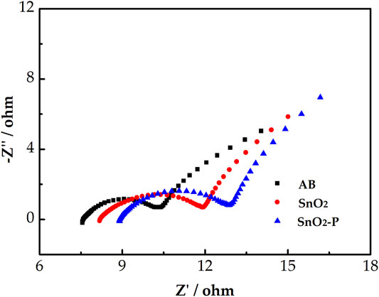
FIGURE 6. Negative Nyquist plots for AB, SnO2, and SnO2-P carried out in 1.6 M V3+ + 3.0 M H2SO4 electrolyte and the simplified electrical equivalent circuit fitting.
Table 1 shows the corresponding fitting electrochemical parameters of the three samples. As shown, Rs follows the order of SnO2-P < SnO2 < AB, which indicates that SnO2-P exhibits the lowest ohmic resistance. In addition, Rct displays the order of SnO2-P < SnO2 < AB. The smaller the Rct, the lower is the charge transfer resistance. The Rct of SnO2 is smaller than that of AB. This is due to SnO2 having a certain catalytic activity and providing active sites. SnO2-P has the smallest Rct because of the increase in electrode conductivity and charge transfer rate due to the P doping. The order of Qt and Qm is AB < SnO2 < SnO2-P. This is because P doping further increases the double-layer and diffusion capacitances, with the charge transfer and diffusion process promoted, respectively.
TABLE 1. Fitting of electrochemical parameters for AB, SnO2, and SnO2-P.
The rate performance of the pristine and SnO2-P modified cells was studied. As shown in Figure 7A, the discharge capacity of the cells reduces with increasing current density, which is because the high current density can produce electrochemical polarization. At 150 mA cm−2, the discharge capacity of the SnO2-P cell increases by 47.3 mA h from 27.1 mA h for the pristine cell. This shows that SnO2-P can improve the discharge capacity of the cell dramatically. Figure 7B presents the coulombic efficiency (CE), which is the ratio of discharge capacity to charge capacity. The CE can be used to reflect the degree of charge loss of cell. The CE using SnO2-P is marginally smaller than that of the pristine cell. It is due to a long charge–discharge time of the SnO2-P cell and serious infiltration of active substances.
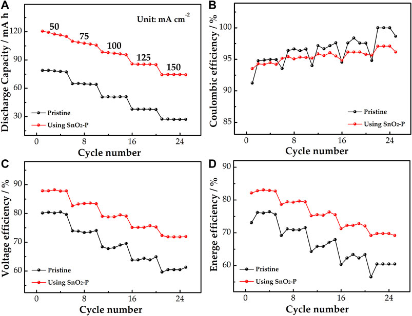
FIGURE 7. Discharge capacity (A), CE (B), VE (C), and EE (D) of pristine and SnO2-P modified cells at a current density of 50–150 mA cm−2.
As shown in Figure 7C, the voltage efficiency (VE) of the SnO2-P cell is increased in comparison with the pristine one. At 150 mA cm−2, the VE of the modified cell (71.9%) is increased by 10.6% compared to the pristine cell (61.3%), illustrating that SnO2-P effectively decreases the electrochemical polarization of the cell. As seen from Figure 7D, the energy efficiency (EE) is jointly determined by the VE and CE. The EE of the two cells decreases with increasing current density. During the whole charge–discharge process, the SnO2-P cell presents a higher EE than the pristine cell. The EE of the modified and pristine cells is 69.2 and 60.5% at 150 mA cm−2. This reveals that the SnO2-P cell has excellent energy storage capacity. The results show that the SnO2-P modified cell has good stability and high energy storage capacity, which can reduce the electrochemical polarization.
Figure 8 shows the relationship between the discharge capacity and voltage of the cells. The charge–discharge curves of pristine and modified cells under all current density are presented in Figures 8A,B, respectively. The discharge capacity gradually decreases with the current density increase under the same control voltage. Compared with the pristine cell, the SnO2-P cell has a lower charge voltage platform and a higher discharge voltage platform at the same current density, which means that it has a smaller charge–discharge voltage difference. This is because SnO2-P can decrease the electrochemical polarization of the cell. SnO2-P increases the mean discharge voltage of the cell, meaning that the energy density of the cell is also enhanced by SnO2-P.
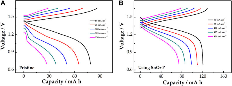
FIGURE 8. Charge–discharge curves of pristine (A) and SnO2-P modified (B) cells at a current density of 50–150 mA cm−2.
In this work, SnO2-P is a new catalyst for the V3+/V2+ redox pair in VRFB. SnO2-P has better electrocatalytic activity and kinetic reversibility than SnO2 and AB. This is because the P doping changes the original structure and thus has higher electrical conductivity, which increases the electron transfer rate of the vanadium redox reaction. The charge–discharge rate performance measurement at 50–150 mA cm−2 demonstrates that the cell using SnO2-P has a larger discharge capacity than the pristine cell, which indicates that the SnO2-P cell possesses a higher electrolyte utilization rate and better electrochemical stability. The VE and EE of the cell with SnO2-P are also greatly improved, indicating that SnO2-P can reduce the electrochemical polarization, and the energy density of the cell is improved. In conclusion, SnO2-P is a new type of VRFB catalyst with excellent potential.
The original contributions presented in the study are included in the article/supplementary material; further inquiries can be directed to the corresponding authors.
XF is mainly responsible for experimental operations and drafting paper. ZZ is mainly responsible for the collecting and processing experimental data. TZ is mainly responsible for collecting information. JX is mainly responsible for drafting the paper. CH is mainly responsible for making important modifications to the manuscript. LD is mainly responsible for reviewing the final manuscript for publication. LW is mainly responsible for designing the experiment. ZH is mainly responsible for the paper guidance.
This work was financially supported by the Hebei Natural Science Fund for Distinguished Young Scholars (No. E2019209433), the Youth Talent Program of the Hebei Provincial Education Department (No. BJ2018020), and the Natural Science Foundation of Hebei Province (No. E2020209151).
The authors declare that the research was conducted in the absence of any commercial or financial relationships that could be construed as a potential conflict of interest.
Ahmed, B., Anjum, D. H., Gogotsi, Y., and Alshareef, H. N. (2017). Atomic Layer Deposition of SnO 2 on MXene for Li-Ion Battery Anodes. Nano Energy 34, 249–256. doi:10.1016/j.nanoen.2017.02.043
Aziz, M. A., Hossain, S. I., and Shanmugam, S. (2020). Hierarchical Oxygen Rich-Carbon Nanorods: Efficient and Durable Electrode for All-Vanadium Redox Flow Batteries. J. Power Sourc. 445, 227329. doi:10.1016/j.jpowsour.2019.227329
Chen, H., Lu, Y., Zhu, H., Guo, Y., Hu, R., Khatoon, R., et al. (2019). Crystalline SnO2 @ Amorphous TiO2 Core-Shell Nanostructures for High-Performance Lithium Ion Batteries. Electrochim. Acta 310, 203–212. doi:10.1016/j.electacta.2019.04.134
Cheng, C., Huang, Z., Zhang, R., Zhou, J., Liu, Z., Zhong, H., et al. (2020). Synthesis of an Emerging Morpholine-Typed Gemini Surfactant and its Application in Reverse Flotation Carnallite Ore for Production of Potash Fertilizer at Low Temperature. J. Clean. Prod. 261, 121121. doi:10.1016/j.jclepro.2020.121121
Chuanchang, L., Bo, Z., and Qingxia, L. (2020). N-eicosane/expanded Graphite as Composite Phase Change Materials for Electro-Driven thermal Energy Storage. J. Energ. Storage 29, 101339. doi:10.1016/j.est.2020.101339
Di Blasi, A., Busaccaa, C., Di Blasia, O., Briguglioa, N., Squadritoa, G., and Antonuccia, V. (2017). Synthesis of Flexible Electrodes Based on Electrospun Carbon Nanofibers with Mn3O4 Nanoparticles for Vanadium Redox Flow Battery Application. Appl. Energ. 190, 165–171. doi:10.1016/j.apenergy.2016.12.129
Fang, T., Jinyu, G., Qiaoyun, R., Xianwen, W., Xiangsi, W., Tao, Z., et al. (2020). Graphene-Wrapped MnO/C Composites by MOFs-Derived as Cathode Material for Aqueous Zinc Ion Batteries. Electrochim. Acta 353, 136570. doi:10.1016/j.electacta.2020.136570
González, Z., Sánchez, A., Blanco, C., Granda, M., Menéndez, R., and Santamaría, R. (2011). Enhanced Performance of a Bi-modified Graphite Felt as the Positive Electrode of a Vanadium Redox Flow Battery. Electrochem. Commun. 13, 1379–1382. doi:10.1016/j.elecom.2011.08.017
He, Z., Cheng, G., Jiang, Y., Li, Y., Zhu, J., Meng, W., et al. (2020). Novel 2D Porous Carbon Nanosheet Derived from Biomass: Ultrahigh Porosity and Excellent Performances toward V2+/V3+ Redox Reaction for Vanadium Redox Flow Battery. Int. J. Hydrogen Energ. 45, 3959–3970. doi:10.1016/j.ijhydene.2019.12.045
Huang, Z., Zhang, S., Wang, H., Liu, R., Cheng, C., Liu, Z., et al. (2020). "Umbrella" Structure Trisiloxane Surfactant: Synthesis and Application for Reverse Flotation of Phosphorite Ore in Phosphate Fertilizer Production. J. Agric. Food Chem. 68, 11114–11120. doi:10.1021/acs.jafc.0c04759
Jelyani, M. Z., Rashid-Nadimi, S., and Asghari, S. (2016). Treated Carbon Felt as Electrode Material in Vanadium Redox Flow Batteries: A Study of the Use of Carbon Nanotubes as Electrocatalyst. J. Solid State. Electrochem. 21, 69–79. doi:10.1007/s10008-016-3336-y
Jiang, Y., Cheng, G., Li, Y., He, Z., Zhu, J., Meng, W., et al. (2021a). Promoting Vanadium Redox Flow Battery Performance by Ultra-uniform ZrO2@C from Metal-Organic Framework. Chem. Eng. J. 415, 129014. doi:10.1016/j.cej.2021.129014
Jiang, Y., Du, M., Cheng, G., Gao, P., Dong, T., Zhou, J., et al. (2021b). Nanostructured N-Doped Carbon Materials Derived From Expandable Biomass with Superior Electrocatalytic Performance towards V2+/V3+ Redox Reaction for Vanadium Redox Flow Battery. J. Energ. Chem. 59, 706–714. doi:10.1016/j.jechem.2020.12.013
Li, Q., Bai, A., Zhang, T., Li, S., and Sun, H. (2020). Dopamine-derived Nitrogen-Doped Carboxyl Multiwalled Carbon Nanotube-Modified Graphite Felt with Improved Electrochemical Activity for Vanadium Redox Flow Batteries. R. Soc. Open Sci. 7, 200402. doi:10.1098/rsos.200402
Li, B., Xue, J., Han, C., Liu, N., Ma, K., Zhang, R., et al. (2021). A Hafnium Oxide-Coated Dendrite-free Zinc Anode for Rechargeable Aqueous Zinc-Ion Batteries. J. Colloid Interf. Sci. 599, 467–475. doi:10.1016/j.jcis.2021.04.113
Liu, J., Yuan, L., Yuan, K., Li, Z., Hao, Z., Xiang, J., et al. (2016). SnO2as a High-Efficiency Polysulfide Trap in Lithium-Sulfur Batteries. Nanoscale 8, 13638–13645. doi:10.1039/c6nr02345b
Liu, X., Feng, G., Wu, Z., Wang, D., Wu, C., Yang, L., et al. (2020). Investigating the Influence of Sodium Sources towards Improved Na3V2 (PO4)3 Cathode of Sodium-Ion Batteries. J. Alloys Compd. 815, 152430. doi:10.1016/j.jallcom.2019.152430
Liu, Z., Li, L., Chen, J., Yang, H., Xia, L., Chen, J., et al. (2021). Effects of Chelating Agents on Electrochemical Properties of Na0.9Ni0.45Mn0.55O2 Cathode Materials. J. Alloys Compd. 855, 157485. doi:10.1016/j.jallcom.2020.157485
Lv, Y., Han, C., Zhu, Y., Zhang, T., Yao, S., He, Z., et al. (2021). Recent Advances in Metals and Metal Oxides as Catalysts for Vanadium Redox Flow Battery: Properties, Structures, and Perspectives. J. Mater. Sci. Technol. 75, 96–109. doi:10.1016/j.jmst.2020.09.042
Mehboob, S., Ali, G., Shin, H.-J., Hwang, J., Abbas, S., Chung, K. Y., et al. (2018). Enhancing the Performance of All-Vanadium Redox Flow Batteries by Decorating Carbon Felt Electrodes with SnO2 Nanoparticles. Appl. Energ. 229, 910–921. doi:10.1016/j.apenergy.2018.08.047
Nie, Y., Xiao, W., Miao, C., Wang, J., Tan, Y., Xu, M., et al. (2021). Improving the Structural Stability of Ni-Rich LiNi0.81Co0.15Al0.04O2 Cathode Materials with Optimal Content of Trivalent Al Ions Doping for Lithium Ions Batteries. Ceramics Int. 47, 9717–9726. doi:10.1016/j.ceramint.2020.12.111
Powell, M. J., Williamson, B. A. D., Baek, S.-Y., Manzi, J., Potter, D. B., Scanlon, D. O., et al. (2018). Phosphorus Doped SnO2 Thin Films for Transparent Conducting Oxide Applications: Synthesis, Optoelectronic Properties and Computational Models. Chem. Sci. 9, 7968–7980. doi:10.1039/c8sc02152j
Skyllas-Kazacos, M., Rychcik, M., Robins, R. G., Fane, A. G., and Green, M. A. (1986). New All-Vanadium Redox Flow Cell. J. Electrochem. Soc. 133, 1057–1058. doi:10.1149/1.2108706
Tseng, T.-M., Huang, R.-H., Huang, C.-Y., Hsueh, K.-L., and Shieu, F.-S. (2013). A Kinetic Study of the Platinum/Carbon Anode Catalyst for Vanadium Redox Flow Battery. J. Electrochem. Soc. 160, A690–A696. doi:10.1149/2.073304jes
Vázquez-Galván, J., Flox, C., Jervis, J. R., Jorge, A. B., Shearing, P. R., and Morante, J. R. (2019). High-power Nitrided TiO2 Carbon Felt as the Negative Electrode for All-Vanadium Redox Flow Batteries. Carbon 148, 91–104. doi:10.1016/j.carbon.2019.01.067
Wang, W. H., and Wang, X. D. (2007). Investigation of Ir-Modified Carbon Felt as the Positive Electrode of an All-Vanadium Redox Flow Battery. Electrochimica Acta 52, 6755–6762. doi:10.1016/j.electacta.2007.04.121
Wang, J., He, Z., Tan, X., Wang, T., He, X., Zhang, L., et al. (2020). Hybrid Supercapacitors from Porous boron-doped diamond with Water-Soluble Redox Electrolyte. Surf. Coat. Technol. 398, 126103. doi:10.1016/j.surfcoat.2020.126103
Wang, T., Li, C., Xie, X., Lu, B., He, Z., Liang, S., et al. (2020). Anode Materials for Aqueous Zinc Ion Batteries: Mechanisms, Properties, and Perspectives. ACS Nano 14, 16321–16347. doi:10.1021/acsnano.0c07041
Wang, B., Yuan, F., Yu, Q., Li, W., Sun, H., Zhang, L., et al. (2021). Amorphous Carbon/graphite Coupled Polyhedral Microframe with Fast Electronic Channel and Enhanced Ion Storage for Potassium Ion Batteries. Energ. Storage Mater. 38, 329–337. doi:10.1016/j.ensm.2021.03.021
Wei, G., Su, W., Wei, Z., Jing, M., Fan, X., Liu, J., et al. (2016). Effect of the Graphitization Degree for Electrospun Carbon Nanofibers on Their Electrochemical Activity Towards VO2+/VO2+ Redox Couple. Electrochim. Acta 199, 147–153. doi:10.1016/j.electacta.2016.03.154
Wu, X., Xu, H., Lu, L., Zhao, H., Fu, J., Shen, Y., et al. (2014). PbO2-modified Graphite Felt as the Positive Electrode for an All-Vanadium Redox Flow Battery. J. Power Sourc. 250, 274–278. doi:10.1016/j.jpowsour.2013.11.021
Wu, X., Zhou, S., Li, Y., Yang, S., Xiang, Y., Jiang, J., et al. (2021). Na-containing Manganese-Based Cathode Materials Synthesized by Sol-Gel Method for Zinc-Based Rechargeable Aqueous Battery. J. Alloys Compd. 858, 157744. doi:10.1016/j.jallcom.2020.157744
Yang, Z., Shancheng, W., Jinqing, P., Yutong, T., Chuanchang, L., Freddy Yin Chiang, B., et al. (2020). Liquid Thermo-Responsive Smart Window Derived from Hydrogel. Joule 4, 2458–2474. doi:10.1016/j.joule.2020.09.001
Ye, J., Yuan, D., Ding, M., Long, Y., Long, T., Sun, L., et al. (2021). A Cost-Effective Nafion/lignin Composite Membrane with Low Vanadium Ion Permeation for High Performance Vanadium Redox Flow Battery. J. Power Sourc. 482, 229023. doi:10.1016/j.jpowsour.2020.229023
Zhang, H., and Sun, C. (2021). Cost-effective Iron-Based Aqueous Redox Flow Batteries for Large-Scale Energy Storage Application: A Review. J. Power Sourc. 493, 229445. doi:10.1016/j.jpowsour.2020.229445
Zhang, F., Huang, S., Wang, X., Jia, C., Du, Y., and Wang, Q. (2018). Redox-targeted Catalysis for Vanadium Redox-Flow Batteries. Nano Energy 52, 292–299. doi:10.1016/j.nanoen.2018.07.058
Zhang, F., Teng, X., Shi, W., Song, Y., Zhang, J., Wang, X., et al. (2020). SnO2 Nanoflower Arrays on an Amorphous Buffer Layer as Binder-free Electrodes for Flexible Lithium-Ion Batteries. Appl. Surf. Sci. 527, 146910. doi:10.1016/j.apsusc.2020.146910
Keywords: vanadium redox flow battery, electrocatalyst, tin dioxide, P doping, energy storage
Citation: Feng X, Zhang Z, Zhang T, Xue J, Han C, Dai L, Wang L and He Z (2021) Enhanced Catalysis of P-doped SnO2 for the V2+/V3+ Redox Reaction in Vanadium Redox Flow Battery. Front. Chem. 9:688634. doi: 10.3389/fchem.2021.688634
Received: 31 March 2021; Accepted: 10 May 2021;
Published: 24 June 2021.
Edited by:
Wei Xiao, Yangtze University, ChinaReviewed by:
Huan Zhang, University of Science and Technology Liaoning, ChinaCopyright © 2021 Feng, Zhang, Zhang, Xue, Han, Dai, Wang and He. This is an open-access article distributed under the terms of the Creative Commons Attribution License (CC BY). The use, distribution or reproduction in other forums is permitted, provided the original author(s) and the copyright owner(s) are credited and that the original publication in this journal is cited, in accordance with accepted academic practice. No use, distribution or reproduction is permitted which does not comply with these terms.
*Correspondence: Chao Han, aGFuY2hhb0BuY3N0LmVkdS5jbg==; Zhangxing He, enhoZUBuY3N0LmVkdS5jbg==
Disclaimer: All claims expressed in this article are solely those of the authors and do not necessarily represent those of their affiliated organizations, or those of the publisher, the editors and the reviewers. Any product that may be evaluated in this article or claim that may be made by its manufacturer is not guaranteed or endorsed by the publisher.
Research integrity at Frontiers
Learn more about the work of our research integrity team to safeguard the quality of each article we publish.