- 1Late Stage USP Development, Bioprocess Development Biologicals, Boehringer Ingelheim Pharma GmbH & Co. KG, Biberach, Germany
- 2M-Star Center Europe GmbH, Sargstedt, Germany
- 3Cell Culture, Process Science, Boehringer Ingelheim, Fremont, CA, United States
The robust scale up of perfusion systems requires comparable conditions over all scales to ensure equivalent cell culture performance. As cells in continuous processes circulate outside the bioreactor, performance losses may arise if jet flow and stirring cause a direct connection between perfusion feed and return. Computational fluid dynamics can be used to identify such short circuit flows, assess mixing efficiencies, and eventually adapt the perfusion setup. This study investigates the scale up from a 2 L glass bioreactor to 100 L and 500 L disposable pilot scale systems. Highly resolved Lattice Boltzmann Large Eddy simulations were performed in single phase and mixing efficiencies (Emix) furthermore experimentally validated in the 2 L system. This evaluation gives insight into the flow pattern, the mixing behavior and information on cell residence time inside the bioreactors. No geometric adaptations in the pilot scale systems were necessary as Emix was greater than 90% for all conditions tested. Two different setups were evaluated in 2 L scale where the direction of flow was changed, yielding a difference in mixing efficiency of 10%. Nevertheless, since Emix was confirmed to be >90% also for both 2 L setups and the determined mixing times were in a similar range for all scales, the 2 L system was deemed to be a suitable scale down model. The results demonstrate how computational fluid dynamic models can be used for rational process design of intensified production processes in the biopharmaceutical industry.
1 Introduction
A rapidly growing population, increased prevalence of diseases as well as rising knowledge and acceptance of biopharmaceuticals has compelled biopharmaceutical companies to optimized processes. In particular the demand for monoclonal antibodies (mAbs) has increased over the past years. The majority of mAbs are typically manufactured in Chinese Hamster Ovary (CHO) cells with fed batch processes as preferred process strategy (Jain and Kumar, 2008; Orellana et al., 2015; Dhara et al., 2018; Kesik-Brodacka, 2018). Nevertheless, the need for higher product yields has encouraged the development of intensified process strategies. Therefore, perfusion processes have become a substantial part of upcoming manufacturing technologies using cell retention to provide higher cell densities. Most common technologies like tangential flow filtration (TFF) or alternating tangential flow (ATF) systems involve a hollow fiber, which is used to circle cells back into the bioreactor while constantly exchanging media (Karst et al., 2016). As an alternative to N-stage perfusion or traditional fed batch processes the less-productive growth phase can also be shifted to the pre-stage, leading to higher volumetric productivities in the N-stage. With such intensified fed batch strategies, the titer was almost doubled compared to low seeded cultures (Stepper et al., 2020).
On the downside perfusion mode also comes with challenges. Besides a technical complex setup, which increases the risk of contamination, high cell densities are responsible for elevated viscosities in the bioreactor and consequently a decrease in mixing efficiency (Ozturk, 1996). Additionally, the combination of jet flow and stirring might induce a direct connection between perfusion feed and retentate flow leading to the formation of a short circuit flow. Accordingly, mixing is of great importance at high cell density cultures (Al-Rubeai, 2015). Poorly mixed reactors can cause local heterogeneities in the cellular environment such as substrate concentration, pH, DO and CO2 gradients (Xing et al., 2009). As a result, the overall performance of the bioreactor may be impaired by decreased cell viability due to extreme pH, poor supply of DO or substrate concentration. The consequences are lower product titer as well as product quality out of specifications (Nadal-Rey et al., 2020).
Over the past decade computational fluid dynamics (CFD) has emerged as an important modelling tool for several applications within the biopharmaceutical environment (Thomas J. A. et al., 2021) or for mixing applications (Nguyen et al., 2014; Bach et al., 2017; Thomas J. et al., 2021). Exemplary use cases are the establishment of a kLa-model in microtiter plates (Wutz et al., 2018), the modeling of heat and mass transport including phase transition in freeze containers (Roessl et al., 2014) as well as the optimization of UF/DF processes including assessment of mixing efficiency (Wutz et al., 2020). Numerical flow simulations of an ATF module were previously performed by Radoniqi et al. (2018). However, the focus of their study was drawn to the lumen of the hollow fiber and the elucidation of membrane fouling rather than the mixing performance inside the tank.
In general, if transient approaches are required traditional simulation schemes can be very expensive in terms of computational costs and time. Promising simulation approaches involving Lattice Boltzmann Large Eddy Simulations (LBLES) speed up high resolved transient simulations when parallelized on graphics processing units (GPU). Their validity for mixing studies has been proven in several studies (Thomas J. A. et al., 2021; Fitschen et al., 2021; Kuschel et al., 2021; Haringa, 2022; Hofmann et al., 2022). Unlike traditional CFD approaches, which numerically approximate the solution of the macroscopic Navier-Stokes and energy equations, the Lattice Boltzmann Method (LBM) approach describes the particle behavior in a flow domain on a mesoscopic scale. LBM-based CFD tools like M-Star numerically solve the Lattice Boltzmann equations (LBE). Therefore, all necessary macroscopic flow variables can be calculated by using particle distribution functions and conservation laws to recover macroscopic equations such as the Navier-Stokes equations. Compared to other approaches the LBM approach is preferable for simulations with complex boundaries. In addition to that, the LBM approach runs faster, as the LBE can be calculated by considering only linear streaming and collision processes rather than constructing the macroscopic continuum equation, in which the calculation of high order occurs (Yan and Zu, 2008; Zhao et al., 2022). Therefore, this approach is specifically suited to describe the transient behavior of complex mixing phenomena as present in continuous perfusion processes.
In this work, the aim was to characterize the mixing performance over various scales of perfusion bioreactors to mitigate the risk of process failure. Initially, a 2 L scale down perfusion reactor was investigated experimentally. The gained experimental data were subsequently used for the validation of mixing efficiencies retrieved from Lattice Boltzmann Method (LBM) CFD simulations. Furthermore, the scale up to 100 L and 500 L pilot scale was investigated simulatively. Besides mixing efficiencies, flow patterns and cell residence times were determined, supporting the assessment of perfusion systems over various scales.
2 Materials and methods
2.1 Reactor setup
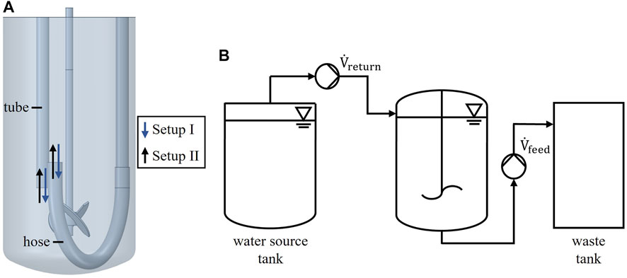
Three different reactor scales were investigated regarding their mixing capabilities when operated in perfusion mode. The laboratory scale reactor had a working volume of 2 L, which was used for both experiment and numerical simulation. The unbaffled tank had an inner diameter of D = 130 mm and was equipped with a 3-blade segment impeller (d = 45 mm). For perfusion a dip tube and U-shaped silicone hose was used as depicted in Figure 1 A. Probes, tubes and sparger are neglected in the figure for simplicity. The pilot scale tanks are commercially available Single-Use Bioreactor (SUB) systems from Thermo Fisher Scientific with working volumes of 100 L and 500 L. The 100 L SUB had a diameter of 437 mm and was equipped with a segment impeller with d = 200 mm. The 500 L SUB had a diameter of 755 mm and was equipped with a segment impeller with d = 320 mm. In perfusion mode inlet and outlet were located as depicted in Figure 6. Further geometric details are displayed in the supplements (Supplementary Figure S1) or can be taken from the vendors website. The pilot scale reactors were only used in numerical simulations.
A standard perfusion setup consists of a perfusion feed, a perfusion return and an inlet for fresh media supply. Product, waste, spent media as well as cells are removed via perfusion feed. Meanwhile, the cells are separated and returned to the perfusion tank via a perfusion return with a bypass flow rate of
2.2 Experimental setup
The perfusion tank was filled with 2 L water for injection (WfI) and
Two different setups, referred to as setup I and setup II are shown in Figure 1 A. WfI was provided via U-shaped hose or vertical tube. The supply of WfI via tube is referred as setup I, the supply via hose as setup II. The measured conductivities of all experiments were within the detection range of the conductivity sensor. Each experiment was carried out for at least five minutes. The stirring speed was set to 250, 350 and 450 rpm. In total, three repetitions were performed for each stirrer speed.
The mixing performance inside the tank is influenced by the perfusion feed, the perfusion return, as well as by the stirrer. In ideal cases the fluid inside the tank is perfectly mixed and there are no mixing phenomena such as short circuit flows that could impact the process performance negatively. For these cases, the dilution can be described by an ideal dilution rate
Whereas the real dilution rate
where
The dilution rate
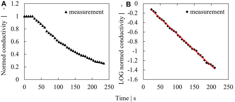
FIGURE 2. Example for dilution rate determination. Measured conductivity signal at an impeller speed of 250 rpm (A), logarithmized concentration (B).
2.3 Numerical simulations
The fluid flow inside the perfusion tank is modeled by the incompressible Navier-Stokes equations, wherein the Lattice-Boltzmann (LB) method is applied as a Navier-Stokes solver. M-Star CFD v. 3.3.77 was used for all CFD simulations. The Navier-Stokes equations describe the mechanics of flows by modeling the conservation of mass, momentum and energy of each fluid particle and is written as (Thomas J. et al., 2021).
The local velocity vector of the fluid particle at a given time
The Boltzmann transport equation is known as (Thomas J. A. et al., 2021)
where
At the tank surface the no-slip condition is assumed, where both fluid and tank have zero velocities applied via a zero-velocity bounce back method. The immersed boundary method is employed for the interaction between fluids and moving impeller which enables to implement a no-slip boundary condition at the impeller surface while moving through the fluid. The top surface of the fluid is treated as a dynamic free surface.
Both, a tracer substance and particles are added after the flow field was developed. The tank inlet is coupled to the tank outlet in terms of flow rate and concentration of the tracer substance so that the total fluid volume and tracer concentration is maintained. The particles are removed at the outlet. This allows to calculate the mixing time including the recirculation loop with the tracer, while the mixing efficiency and particle residence time is calculated with the help of the particles in a single simulation. The examination of the particles starts after one full mixing time with 95% homogeneity of the tracer has passed.
The concentration evolves locally according to the convection-diffusion equation
and the particles are treated as tracer particles without any size or forces. Hereby
A grid study was performed to assure that the numerical solution was independent of the applied grid. As can be found in the supplementary material 1.2 a grid with a total number of 25.2 million grid points was sufficient to reach grid independence for the determination of power number and kinetic energy in case of the laboratory scale 2 L perfusion bioreactor. For the 100 L bioreactor grid independence was reached with 13.7 million grid points and for 500 L with 14.5 million grid points, respectively.
3 Results and discussion
The mixing efficiency of a 2 L laboratory perfusion bioreactor was assessed by experimental conductivity measurement as well as by transient numerical flow simulations. Characterization data were compared to simulated pilot scale bioreactors of 100 L and 500 L working volume to support the scale up of perfusion processes.
3.1 Simulation and validation of a lab scale perfusion bioreactor
The mixing efficiency was determined for various power inputs as described in Section 2. Two setups were tested. In setup I, the tube served as inlet and the U-shaped hose as outlet, whereas the pumping direction was changed for setup II. Experimental as well as simulated data are depicted in Figure 3. In most cases a very high mixing efficiency with values greater than 90% was reached indicating that the jet flow coming from the retentate pipe shows no direct connection to the reactor outlet by perfusion feed flow. Setup I shows a constant mixing efficiency of 97–100% over the tested power inputs as can be seen in Figure 3. Very good agreement was reached for simulated results compared to experimental data with less than 1.5% deviation. Changing the direction of flow, however, led to reduced mixing efficiencies as depicted in Figure 3. Interestingly, instead of increasing mixing efficiencies, higher power inputs resulted in decreased performance with values of 83% (exp) and 90% (sim) for 58 W/m³. While discrepancies between experimental and simulated mixing efficiencies were still acceptable for 10 W/m³ and 27 W/m³ with a relative deviation of <5%, highest discrepancies occurred for 58 W/m³ with 8%. This can be attributed to fluctuations in conductivity signal due to different flow conditions compared to setup I and increased turbulence by higher power inputs. Alternatively, Emix might be overestimated by the numerical simulation for the given flow conditions.
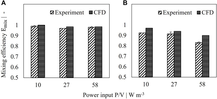
FIGURE 3. Comparison of simulated and measured mixing efficiency of 2 L perfusion tank. (A) Setup I, (B) Setup II.
Figure 4 and Figure 5 help to better understand the underlying flow conditions. Orange streamlines represent the retentate flow coming into the reactor and blue streamlines the perfusion feed flow leaving the reactor. Noticeably, independent of the power input no short circuit flow occurs in setup I, as streamlines indicate no direct connection between inlet and outlet (Figure 4). The flow induced by the impeller generates a flow field which is oriented in a similar direction compared to the incoming jet flow. Higher power inputs (Figure 4C) compared to lower power inputs (Figure 4A) do not lead to a stronger diversion of the incoming flow, thus mixing efficiency is rather unaffected. In contrast to setup I, jet flow and the flow by agitation strongly interact in setup II. Especially for higher power inputs (Figure 5C), the incoming jet flow is diverted by agitation leading to an overlap of streamlines from inlet and outlet. These flow conditions led to a drop in Emix and may also be the cause of fluctuating signal of the conductivity probe. Streamlines of setup I and II from a different angle can be also found in the supplements.
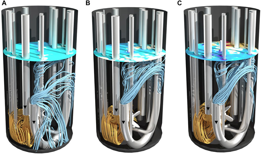
FIGURE 4. Streamlines in 2 L bioreactor of setup I at different power inputs (A) 10 W/m³, (B) 27 W/m³ and (C) 58 W/m³. Streamlines calculated forwards in orange as inflow and streamlines calculated backwards in blue as outflow. The surface color indicates the topology of the vortex.
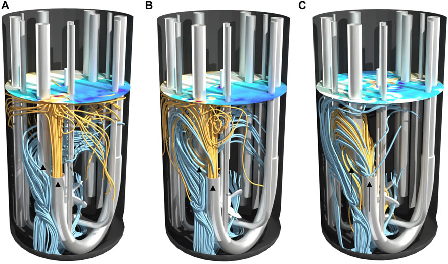
FIGURE 5. Streamlines in 2 L bioreactor of setup II at different power inputs (A) 10 W/m³, (B) 27 W/m³ and (C) 58 W/m³. Streamlines calculated forwards in orange as inflow and streamlines calculated backwards in blue as outflow. The surface color indicates the topology of the vortex.
In general, the findings show that a numerical approach involving LBLES simulations is suitable to depict the mixing efficiency in a continuous process. Both experiment and simulation indicate a higher robustness of setup I towards changing power inputs, whereas the loss of mixing efficiency for elevated stirrer speeds in setup II is reasonably captured by the simulation.
3.2 Assessment of mixing performance during perfusion scale up
To minimize the risk of process failure due to insufficient mixing in larger scales, two pilot scale reactors of 100 L and 500 L working volume respectively were also evaluated regarding their mixing efficiency when operated in perfusion mode. Since lab scale experiments showed good agreement of experimental and simulated values, pilot scale reactors were only characterized by computational fluid dynamics.
Streamlines of the 100 L and 500 L reactors are depicted in Figure 6. Similar to the 2 L bioreactor, no short circuit flow can be detected. In fact, both tanks indicate a good mixing behavior as streamlines show an axial distribution of the incoming liquid.
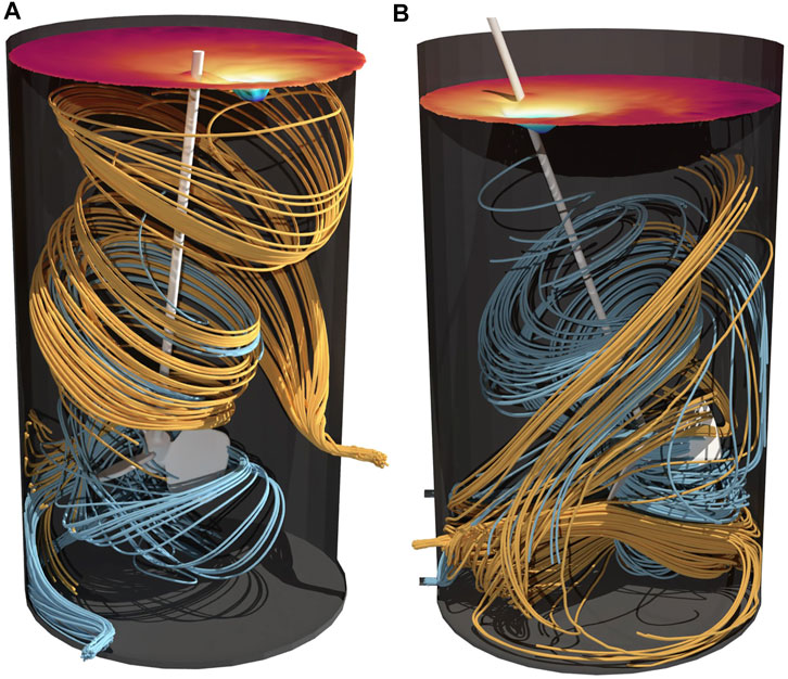
FIGURE 6. Streamlines in 100 L (A) and 500 L (B) perfusion bioreactor. Streamlines calculated forwards in orange as inflow and streamlines calculated backwards in blue as outflow. The surface color indicates the topology of the vortex.
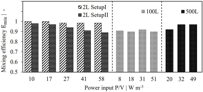
Homogenous distribution of the retentate flow within the pilot scale perfusion tanks can also be assumed due to high mixing efficiencies (see Figure 7). Emix remains greater than 90% over various power inputs, proving a robust behavior of the reactor setup. Consequently, no geometric changes are necessary since sufficient mixing efficiency is reached. Considering the 2 L as scale down model, single phase simulations for setup II resulted in absolute values closer to pilot scale, whereas setup I seems to overperform. However, no significant impact is expected for mixing efficiencies above 90%. Accordingly, both setups are assumed to be suitable scale down models.
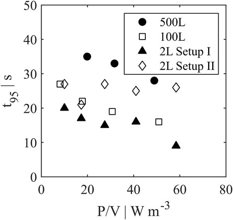
Besides mixing efficiency, the mixing time t95 (Figure 8) can be used to assess the performance among the different scales. With increasing power input the mixing time decreased for all reactor scales except for setup II in 2 L scale. As described above, the interaction of jet flow and flow field by agitation may lead to a hampered distribution of incoming retentate flow resulting in higher mixing times. The 500 L reactor showed values of 28–35 s, the 100 L reactor resulted in lower values of 16–27 s. Similar to mixing efficiencies, setup II showed t95 closer to pilot scale with 21–27 s, while setup I overperformed with lowest mixing times of 9–20 s. Nevertheless, differences between mixing times for all scales are deemed uncritical for cell culture (Lara et al., 2006).
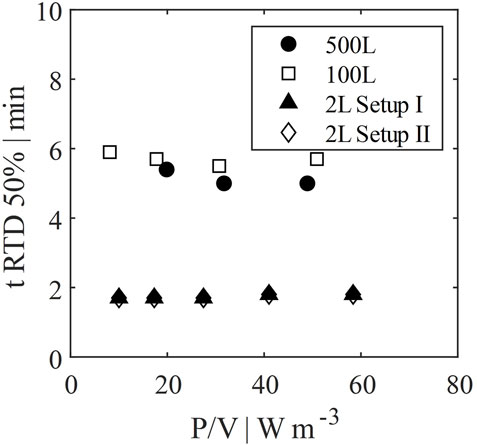
The residence time until 50% of all cells have left the perfusion tank at least once was evaluated via particle tracking by CFD. Results are shown in Figure 9. This time can be interpreted as a measure for the frequency of cells being exposed to the pump or hollow fiber of the perfusion tank. The time is dependent on the recirculation flow rate, as well as on the mixing efficiency. However, since Emix was very high in all cases, the latter has only minor influence on the residence time. Considering that scale up was based on identical wall shear rates, the resulting ratio of recirculation rate to working volume was similar for 100 L and 500 L scale in contrast to the 2 L scale. Thus, the residence time in the 2 L scale down model is much lower. In other words, the frequency of cells entering the recirculation loop is much higher, which might lead to potentially higher stress for the cells (Neunstoecklin et al., 2015; Fries et al., 2016).
In summary, LBLES simulations of pilot scale perfusion reactors showed that no reactor adaptations were necessary to reach sufficient mixing efficiency. Additionally, an assessment of the 2 L scale down model was performed. Results showed that both evaluated setups are capable to mimic pilot scale conditions with a slight preference towards setup II. The higher exposure frequency of the cells to the recirculation loop cannot be scaled with the given setup and may result in performance differences.
4 Conclusion
The determination of mixing efficiency and prevention of short circuit flows is an essential part of the characterization and optimization of perfusion systems. To ensure robust process performance such criteria should be kept constant among various scales. Lattice Boltzmann Large Eddy simulations have been proven as valuable tools capable of highly resolved transient simulation. This study shows the assessment of mixing efficiency via LBLES and its validation in a 2 L laboratory scale perfusion reactor. Discrepancies between simulation and experiment were below 5% with one exception of 8% for two reactor setups and several power inputs.
The scale up into 100 L and 500 L pilot scale was investigated by simulation of flow patterns, mixing efficiency, mixing time and residence time distribution of cells in the perfusion reactor. In all cases mixing efficiencies of >90% were achieved. Accordingly, no geometric adaptations of the reactor systems were necessary. The 2 L system was demonstrated to be a suitable scale down model for the pilot scale perfusion considering the examined criteria. Results for setup II slightly better matched pilot scale performance, however, differences for the two laboratory scale reactor setups were deemed non-crucial. In summary, this LBLES approach is recommended in the scale up of perfusion processes as a risk mitigation measure to prevent process failure by short circuit flow. Since this study only included single-phase simulations, future work should focus on multi-phase systems. If the gas phase is considered, flow patterns would differ, potentially leading to altered mixing times and efficiencies. Eventually, all simulated results have to be confirmed by cell culture cultivations.
Data availability statement
The original contributions presented in the study are included in the article/Supplementary Material, further inquiries can be directed to the corresponding authors.
Author contributions
Conceptualization, MK, JW, DM, and TW; methodology, MK and JW; investigation and analysis, MK, JW, and MS; original draft, MK, MS, and JW; review and editing, MK, JW, TW, DM, and MS.
Acknowledgments
The authors acknowledge Erik Hasenfus from Boehringer Ingelheim for creating the 3D geometries.
Conflict of interest
Authors MK, MS, and TW were employed by Boehringer Ingelheim Pharma GmbH & Co. KG. JW was employed by M-Star Center Europe GmbH. DM was employed by Boehringer Ingelheim.
Publisher’s note
All claims expressed in this article are solely those of the authors and do not necessarily represent those of their affiliated organizations, or those of the publisher, the editors and the reviewers. Any product that may be evaluated in this article, or claim that may be made by its manufacturer, is not guaranteed or endorsed by the publisher.
Supplementary material
The Supplementary Material for this article can be found online at: https://www.frontiersin.org/articles/10.3389/fceng.2023.1076509/full#supplementary-material
References
Al-Rubeai, M. (2015). Animal cell culture. 1st ed. (Switzerland: Springer International Publishing).
Bach, C., Yang, J., Larsson, H., Stocks, S. M., Gernaey, K. V., Albaek, M. O., et al. (2017). Evaluation of mixing and mass transfer in a stirred pilot scale bioreactor utilizing CFD. Chem. Eng. Sci. 171, 19–26. doi:10.1016/j.ces.2017.05.001
Dhara, V. G., Naik, H. M., Majewska, N. I., and Betenbaugh, M. J. (2018). Recombinant antibody production in CHO and NS0 cells: Differences and similarities. BioDrugs 32 (6), 571–584. doi:10.1007/s40259-018-0319-9
Fitschen, J., Hofmann, S., Wutz, J., Kameke, A. v., Hoffmann, M., Wucherpfennig, T., et al. (2021). Novel evaluation method to determine the local mixing time distribution in stirred tank reactors. Chem. Eng. Sci. X 10, 100098. doi:10.1016/j.cesx.2021.100098
Fries, T., Dittler, I., Blaschczok, K., Löffelholz, C., Dornfeld, W., Schöb, R., et al. (2016). Quantifizierung der hydromechanischen Beanspruchung von Pumpen auf tierische Zellen mittels des nicht-biologischen Modellsystems Emulsion. Chem. Ing. Tech. 88, 177–182. doi:10.1002/cite.201500126
Haringa, C., Tang, W., Deshmukh, A. T., Xia, J., Reuss, M., Heijnen, J. J., et al. (2022). Euler-Lagrange computational fluid dynamics for (bio)reactor scale down: An analysis of organism lifelines. Eng. Life Sci. 23, 652–663. doi:10.1002/elsc.201600061
Hofmann, S., Weiland, C., Fitschen, J., Kameke, A., Hoffmann, M., and Schlüter, M. (2022). Lagrangian sensors in a stirred tank reactor: Comparing trajectories from 4D-Particle Tracking Velocimetry and Lattice-Boltzmann simulations. Chem. Eng. J. 449, 137549. doi:10.1016/j.cej.2022.137549
Jain, E., and Kumar, A. (2008). Upstream processes in antibody production: Evaluation of critical parameters. Biotechnol. Adv. 26 (1), 46–72. doi:10.1016/j.biotechadv.2007.09.004
Karst, D. J., Serra, E., Villiger, T. K., Soos, M., and Morbidelli, M. (2016). Characterization and comparison of ATF and TFF in stirred bioreactors for continuous mammalian cell culture processes. Biochem. Eng. J. 110, 17–26. doi:10.1016/j.bej.2016.02.003
Kesik-Brodacka, M. (2018). Progress in biopharmaceutical development. Biotechnol. Appl. Biochem. 65 (3), 306–322. doi:10.1002/bab.1617
Krüger, T., Kusumaatmaja, H., Kuzmin, A., Shardt, O., Silva, G., and Viggen, E. M. (2017). The lattice Boltzmann method, principles and practice. Graduate Texts Phys. doi:10.1007/978-3-319-44649-3
Kuschel, M., Fitschen, J., Hoffmann, M., Kameke, A., and Wucherpfennig, T. (2021). Validation of novel lattice Boltzmann large eddy simulations (LB LES) for equipment characterization in biopharma. Processes 9 (6), 950. doi:10.3390/pr9060950
Lara, A. R., Galindo, E., Ramírez, O. T., and Palomares, L. A. (2006). Living with heterogeneities in bioreactors: Understanding the effects of environmental gradients on cells. Mol. Biotechnol. 34 (3), 355–382. doi:10.1385/mb:34:3:355
Nadal-Rey, G., McClure, D. D., Kavanagh, J. M., Cornelissen, S., Fletcher, D. F., and Gernaey, K. V. (2020). Understanding gradients in industrial bioreactors. Biotechnol. Adv. 46, 107660. doi:10.1016/j.biotechadv.2020.107660
Neunstoecklin, B., Stettler, M., Solacroup, T., Broly, H., Morbidelli, M., and Soos, M. (2015). Determination of the maximum operating range of hydrodynamic stress in mammalian cell culture. J. Biotechnol. 194, 100–109. doi:10.1016/j.jbiotec.2014.12.003
Nguyen, D., Rasmuson, A., Björn, I. N., and Thalberg, K. (2014). CFD simulation of transient particle mixing in a high shear mixer. Powder Technol. 258, 324–330. doi:10.1016/j.powtec.2014.03.041
Orellana, C. A., Marcellin, E., Schulz, B. L., Nouwens, A. S., Gray, P. P., and Nielsen, L. K. (2015). High-Antibody-producing Chinese hamster ovary cells up-regulate intracellular protein transport and glutathione synthesis. J. Proteome Res. 14 (2), 609–618. doi:10.1021/pr501027c
Ozturk, S. S. (1996). Engineering challenges in high density cell culture systems. Cytotechnology 22 (1–3), 3–16. doi:10.1007/bf00353919
Radoniqi, F., Zhang, H., Bardliving, C. L., Shamlou, P., and Coffman, J. (2018). Computational fluid dynamic modeling of alternating tangential flow filtration for perfusion cell culture. Biotechnol. Bioeng. 115 (11), 2751–2759. doi:10.1002/bit.26813
Roessl, U., Jajcevic, D., Leitgeb, S., Khinast, J. G., and Nidetzky, B. (2014). Characterization of a laboratory-scale container for freezing protein solutions with detailed evaluation of a freezing process simulation. J. Pharm. Sci. 103 (2), 417–426. doi:10.1002/jps.23814
Stepper, L., Filser, F. A., Fischer, S., Schaub, J., Gorr, I., and Voges, R. (2020). Pre-stage perfusion and ultra-high seeding cell density in CHO fed-batch culture: A case study for process intensification guided by systems biotechnology. Bioprocess Biosyst. Eng. 43 (8), 1431–1443. doi:10.1007/s00449-020-02337-1
Thomas, J. A., Liu, X., DeVincentis, B., Hua, H., Yao, G., Borys, M. C., et al. (2021a). A mechanistic approach for predicting mass transfer in bioreactors. Chem. Eng. Sci. 237, 116538. doi:10.1016/j.ces.2021.116538
Thomas, J., Sinha, K., Shivkumar, G., Cao, L., Funck, M., Shang, S., et al. (2021b). A CFD digital twin to understand miscible fluid blending. AAPS PharmSciTech 22 (3), 91. doi:10.1208/s12249-021-01972-5
Wutz, J., Steiner, R., Assfalg, K., and Wucherpfennig, T. (2018). Establishment of a CFD-based kLa model in microtiter plates to support CHO cell culture scale-up during clone selection. Biotechnol. Prog. 34 (5), 1120–1128. doi:10.1002/btpr.2707
Wutz, J., Waterkotte, B., Heitmann, K., and Wucherpfennig, T. (2020). Computational fluid dynamics (CFD) as a tool for industrial UF/DF tank optimization. Biochem. Eng. J. 160, 107617. doi:10.1016/j.bej.2020.107617
Xing, Z., Kenty, B. M., Li, Z. J., and Lee, S. S. (2009). Scale-up analysis for a CHO cell culture process in large-scale bioreactors. Biotechnol. Bioeng. 103 (4), 733–746. doi:10.1002/bit.22287
Yan, Y. Y., and Zu, Y. Q. (2008). Numerical simulation of heat transfer and fluid flow past a rotating isothermal cylinder – a LBM approach. Int. J. Heat Mass Transf. 51 (9–10), 2519–2536. doi:10.1016/j.ijheatmasstransfer.2007.07.053
Keywords: perfusion, scale up, computational fluid dynamics, lattice boltzmann, large eddy simulation, mixing
Citation: Kuschel M, Wutz J, Salli M, Monteil D and Wucherpfennig T (2023) CFD supported scale up of perfusion bioreactors in biopharma. Front. Chem. Eng. 5:1076509. doi: 10.3389/fceng.2023.1076509
Received: 21 October 2022; Accepted: 09 January 2023;
Published: 18 January 2023.
Edited by:
Thomas Kaspar Villiger, University of Applied Sciences and Arts Northwestern Switzerland, SwitzerlandReviewed by:
Gregor Wehinger, Clausthal University of Technology, GermanyHouari Ameur, University Centre of Naama, Algeria
Copyright © 2023 Kuschel, Wutz, Salli, Monteil and Wucherpfennig. This is an open-access article distributed under the terms of the Creative Commons Attribution License (CC BY). The use, distribution or reproduction in other forums is permitted, provided the original author(s) and the copyright owner(s) are credited and that the original publication in this journal is cited, in accordance with accepted academic practice. No use, distribution or reproduction is permitted which does not comply with these terms.
*Correspondence: Thomas Wucherpfennig, VGhvbWFzLnd1Y2hlcnBmZW5uaWdAYm9laHJpbmdlci1pbmdlbGhlaW0uY29t
 Maike Kuschel
 Johannes Wutz2
 Mustafa Salli