 Lifang Yan
 Yi Cheng
- Department of Chemical Engineering, Tsinghua University, Beijing, China
The mixing process between miscible fluids in a splitting-and-recombination microreactor is analyzed numerically by solving the Navier–Stokes equation and species transfer equation. The commercial microreactor combines rectangular channels with comb-shaped inserts to achieve the splitting-and-recombination effect. The results show that the microreactor with three-layer standard inserts have the highest mixing rate as well as good mixing efficiency within a wide range of Reynolds numbers from 0.1 to 160. The size parameters of the inserts, both the ratio of the width of comb tooth (marked as l) and the spacing distance (marked as s) between two comb teeth, and the ratio of the vertical distance (marked as V) of comb teeth and the horizontal distance (marked as H) are essential for influencing the liquid–liquid mixing process at low Reynolds numbers (e.g., Re ≤ 2). With the increase of s/l from 1 to 4, the mixing efficiency drops from 0.99 to 0.45 at Re = 0.2. Similarly, the increase in V/H is not beneficial to promote the mixing between fluids. When the ratio of V/H changes from 10:10 to 10:4, the splitting and recombination cycles reduce so that the uniform mixing between different fluids can be hardly achieved. The width of comb tooth (marked as l) is 1 mm and the spacing distance (marked as s) between two comb teeth is 2 mm. The vertical distance (marked as V) of comb teeth and the horizontal distance (marked as H) are both 10 mm.
1 Introduction
In the past 2 decades, microreaction technology has developed rapidly, becoming an emerging technique widely used in the synthesis of drugs, high-end fine chemicals, and nanomaterials (Jensen, 2017). As the micro-scale mixing of fluids is critical in determining the performance of the microreactor, designing efficient and practical micro-mixing devices has mostly been a concern (Hessel et al., 2005; Suh and kang, 2010; Ward and Fan, 2015; Lee et al., 2016; Cai et al., 2017). Convection effect tends to dominate at macroscopic scales, while the mixing in microfluidic devices largely relies on the molecular diffusion process due to low Reynolds numbers (less than 100) (Viktorov et al., 2015). However, the molecular diffusion is so slow that complete mixing of two fluids in a simple channel such as the T channel requires a long time and mixing distance. According to the Fick’s law, the diffusive flux increases linearly with the concentration gradient, and the diffusion time is proportional to the square of the diffusion distance. Consequently, it is necessary to minimize the diffusion distance between fluids and maximize the interfacial area and concentration gradient for a rapid and efficient mixing process (Hessel et al., 2005; Feng et al., 2013).
The micromixer can be classified into active and passive mixers, respectively, considering whether or not an external field is present (Nguyen and Wu, 2005; Lee et al., 2011). The active micromixer relies on an external field to enhance mixing, such as electric field, magnetic field, or ultrasonic wave, whereas, the passive micromixer benefits from the structure design of the channel to obtain sufficient contact of fluids. In recent years, aiming for the fast mixing rate and high mixing efficiency, a number of new passive mixers have been proposed. As far as the laminar flow is concerned, the concept of “splitting and recombination (SAR)” has been proposed to increase the interfacial area between the fluids as much as possible (Hao and Meiners, 2004; Ansari and Kim, 2010; Chen et al., 2011; Lim et al., 2011; Feng et al., 2013). In this method, the fluid is first split into multi-layer fluids followed by recombination. Through sequential splitting and recombination, the diffusion distance between fluids is continuously reduced, and the contact area is constantly updated. As a result, the mixing performance is significantly improved. Feng et al. (2013) designed an SAR mixer with a double-layer XH-shaped structure, which can realize continuous rotation of the contact surface between fluids. Based on the results of numerical simulations and experiments, they proved that the mixer exhibited good mixing performance in a wide range of Re (0 < Re < 60), and the mixing efficiency was higher than 89.4%. Ansari and Kim (2010) proposed a new planar SAR microreactor which could achieve unbalanced collisions at recombination unit by designing unequal width of rhombic sub-channels. It was found that the width ratio of the sub-channels was the most important design parameter and the micromixer with symmetrical sub-channels had the lowest mixing efficiency. In addition, efforts have been made to improve the mixing performance of the mixer by inducing chaotic advection or vortexes (Xia et al., 2005; Ansari and Kim, 2009; Li et al., 2012; Lin, 2015; Yang et al., 2015; Hossain et al., 2017). For chaotic convection, mixing between fluids depends on the process of splitting, stretching, folding, and breaking up of the fluid. Chaotic convection is mainly realized by designing curved, spiral, or more complex channels. Li et al. (2012) designed an S-shaped micromixer to induce the Dean vortex through numerical simulation. On this basis, they fabricated a two-dimensional planar labyrinth mixer and carried out the experimental test. The results showed that the labyrinth mixer could achieve rapid and efficient mixing. With Re ranging between 2.5 and 30, the mixing time was between 9.8 s and 32 ms. Furthermore, a series of novel and efficient micromixers have been proposed based on the combination of different mixing mechanisms (Zhang et al., 2011; Liu et al., 2015; Raza et al., 2018; Raza and Kim, 2019a; Raza and Kim, 2019b; Gidde, 2019). Raza and Kim (2019a) designed an asymmetric planar micromixer by numerical simulation, which combines the splitting-and-recombination mixing unit with the curved channels containing obstructions. In this micromixer, two streams of fluids from subchannels with different width collide unevenly at the recombination unit, and vortexes are generated in the curved channel with radial baffle. Consequently, the mixing index was higher than 0.9 at Re ≥ 20. Liu et al. (2015) proposed a 3D cross-linked dual helical micromixer. In the dual helical channels in which the directions are opposite, two streams of fluids were split, accompanied by chaotic convection, while in the crossing region, two streams of fluids realized recombination. The mixer enabled to achieve full mixing at low Reynolds numbers (0.03–30).
The passive mixers mentioned above often rely on the design of an ingenious channel structure to achieve efficient mixing process. Such micro-mixing devices are difficult to produce on a large scale due to the difficulty of fabrication. Herein, we reported the design of a commercial microreactor that enables an easy splitting and recombination mixing process by combining simple rectangular channels with comb-shaped inserts. In this study, the computational fluid dynamics method (CFD) is employed to investigate the liquid mixing process in this commercial microreactor. The effects of the number of layers and size parameters of standard inserts on mixing performance and pressure drop are studied in detail.
2 A Splitting-and-Recombination Microreactor: Geometry, Modeling, and Simulation
Figure 1 shows the design of a commercial microreactor which combines rectangular channels with comb-shaped inserts, which has eight channels in series with a channel cross-sectional area of 12 × 1.5 mm2. It holds the advantage of having removable and structured inserts, providing a high surface-to-volume ratio and continuous and intensive cross-mixing capability. Figure 2A illustrates the specific size of the standard insert. The width of comb tooth (marked as l) is 1 mm, and the spacing distance (marked as s) between two comb teeth is 2 mm. The vertical distance (marked as V) of comb teeth and the horizontal distance (marked as H) are both 10 mm. The total length of an insert is 60 mm. The structured inserts can be placed one on top of another in several layers to form a fine flat grid. The influence of size parameters (s/l and V/H) on the mixing process is subsequently investigated. In general, there are three inserts inside a channel with an insert thickness of 0.5 mm. Therefore, modeling the whole reactor would result in an excessive number of grids, which is not a cost-efficient way in terms of simulation. Therefore, the model is reasonably simplified and only a single channel is modeled. The simplified three-dimensional model is shown in Figure 2B.
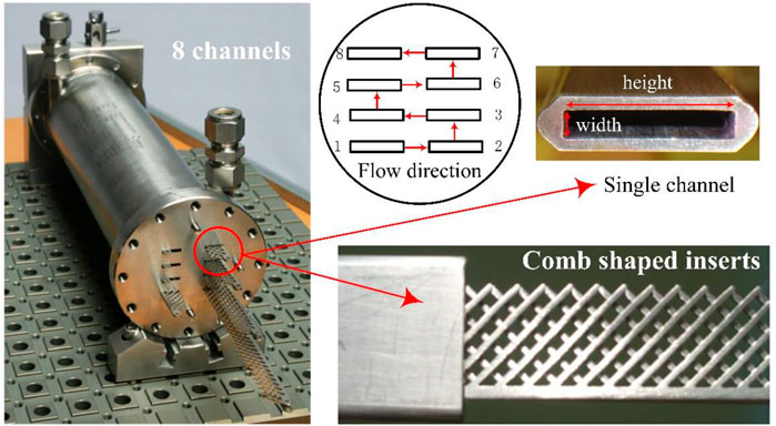
FIGURE 1. Photo of a commercial microreactor with detailed inset structures.
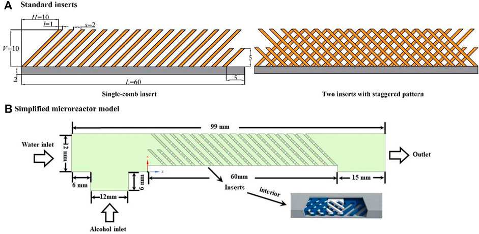
FIGURE 2. Schematic diagram of standard inserts [(A), s/l = 2, V/H = 10:10] and (B) a simplified microreactor model.
The liquid–liquid flow and mixing process are analyzed numerically by using commercial software Fluent. In the simulation, the flow is regarded as the laminar flow because of the low Re (Re < 160) in the microreactor, and the liquid is considered incompressible due to low pressure drop and constant temperature in the flow process. The governing equations to be solved include conservation equations of mass, momentum, and species.
The mass conservation equation, or called as continuity equation, is given by the following:
The momentum equation, or Navier–Stokes equation, can be written as follows:
where ρ is the density of fluid, kg/m3; p is the static pressure, Pa;
In Fluent, the species transfer model is described as a convection–diffusion equation for the ith species, the general form is as follows:
where Yi is the local mass fraction of species i, Ri is the net rate of production of species by chemical reaction, and
Here, Di,m is the mass diffusion coefficient for species i is the mixture, m2/s.
Two liquids are chosen as the working fluids in the simulation process, that is, water and ethanol. The densities of water and ethanol are 998.2 kg/m3 and 790 kg/m3, respectively, and their viscosities are 0.0010 and 0.0012 Pa·s, respectively. The diffusion coefficient of ethanol in water is 1.2 × 10⁻⁹ m2/s. It is known that they are miscible in any proportion. However, the model ignores the molecular interaction between water and ethanol to simplify the mixing simulation. In the simulation, the convergence condition is that the relative residual is less than 1 × 10⁻⁷ and the water concentration at outlet remains constant.
In order to quantitatively analyze the mixing process, the mixing index (MI) is employed to evaluate the mixing efficiency. The specific calculation formula is as follows:
Here, cp is the point concentration at the cross-sectional plane perpendicular to the flow direction, mol/m3.
The MI compares the standard deviation with the average concentration, and its value range is between 0 and 1. When MI = 1, it indicates that the concentration at the cross section is uniform, and two fluids are fully mixed. When MI = 0, it means that the point concentration at the cross section fluctuates greatly, and the two fluids hardly mix.
In addition, the pressure drop is calculated to evaluate energy consumption.
The Re number is calculated based on average density and viscosity.
where dH is the hydraulic diameter of the main channel, m. u is the velocity normal to flow direction at the inlet, m/s.
The combination of hexahedral and polyhedral meshes are selected to reduce the computation time. In the simulation, the pressure-based solver is used to calculate the steady flow process. To improve the calculation accuracy, the PISO (Pressure-Implicit with Splitting of Operators) scheme is chosen for pressure–velocity coupling; second-order upwind scheme for the pressure interpolation and momentum.
For boundary condition, two entrances which feed liquids respectively are set as “velocity inlet,” the outlet is set as “pressure outlet,” and all walls are no-slip.
3 Results and Discussion
3.1 Grid Independency Test
The number of grids directly determines the reliability of simulation results. In general, a smaller size of grids is beneficial to improve the calculation accuracy. However, it may result in a longer calculation time and higher requirement for computer hardware. Therefore, the grid independency test was first carried out for the aim of determining the optimal number of grids. Figure 3 compares the mixing index with different number of cells which varies from 3.337 million to 24.576 million. The mixing index along the main channel is almost the same with 13.178 million and 24.576 million cells, both at Re = 0.2 and Re = 99. Therefore, the optimal number of cells is 13.178 million for three-layer standard inserts.
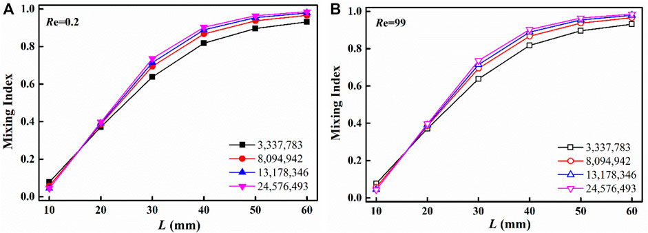
FIGURE 3. Grid independency test: mixing index along the main channel (standard inserts with three layers): (A) Re = 0.2 and (B) Re = 99.
For other cases, such as different number of layers or other shapes of inserts, the grid independency was also tested first, and the optimal number of cells was between 10 million and 25 million.
3.2 The Number of Layers of Inserts
The number of layers of inserts plays an important role in liquid–liquid mixing, which imposes more disturbances on the liquid flows and their interaction. Figure 4 presents the effect of the number of layers of inserts. The general variation of mixing index with Re can be roughly divided into three ranges (such as 2, 3, and 4 layers in Figure 4). First of all, when Re ≤ 10, which is in the low Re range, molecular diffusion plays a dominant role in the mixing process compared with convective diffusion. Consequently, the mixing performance mainly depends on the residence time of the fluid in the microreactor. When the velocity of the fluid is very low, the residence time is sufficient to guarantee the overall mixing performance between species. It is clear that the mixing index decreases rapidly due to the decrease of residence time with the increase of Re. Moreover, when Re is in the intermediate region, that is, 10 < Re ≤ 100, the inertial force which benefits to induce secondary flow becomes more important in the mixing process. When Re continues to increase, the residence time is further shortened, but the secondary flow is strengthened significantly. Therefore, the mixing index starts to improve with the increase of Re. Finally, in the higher Re range, that is, 100 < Re < 160, the secondary flow is further enhanced. Through stretching and folding of the interface between fluids, mixing can be realized at a faster speed. In this range, the mixing index basically does not change with the increase of Re.
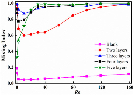
FIGURE 4. Mixing index at the outlet of the microreactor with different number of layers (standard inserts, s/l = 2, V/H = 10:10, l = 1 mm, V = 10 mm).
As can be seen from Figure 4, compared with the empty rectangular channel, the standard inserts greatly improve the mixing efficiency. The mixing efficiency remains at a low level (MI < 0.20) for Re between 0.1 and 160 when the microreactor is just an empty rectangular channel without inserts. However, the mixing index is greatly improved to 0.86 when three-layer standard inserts are placed into the main channel. When Re is greater than 100, the mixing index which maintains above 0.90 shows no significant difference, even if the number of insert layers changes from two to five. It is interesting to note that for microreactor with different layers of inserts, there are obvious differences in the Re range from 0.1 to 40. The specific reasons will be analyzed later.
Figure 5 shows the pressure drop data under the conditions with different number of layers. It is within our expectation that increasing the number of layers brings higher pressure drop due to more complex fluid flow resistance.
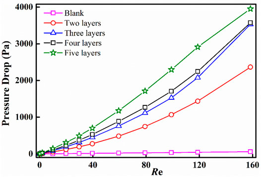
FIGURE 5. Pressure drop under the conditions with different number of layers (standard inserts, s/l = 2, V/H = 10:10, l = 1 mm, V = 10 mm).
For better understanding the mixing differences in the microreactor with different number of insert layers, the concentration distribution of water and velocity vectors on the x-y planes which are normal to flow direction are analyzed in detail. The positions of selected x-y planes are shown in Figure 6 and marked as A-A′, B-B′ … H-H′, respectively. In addition, the z coordinate position of A-A′ plane is set as z = 0 mm, and then other planes z = 12, 13, 14, 42, 43, 44, and 60 mm.
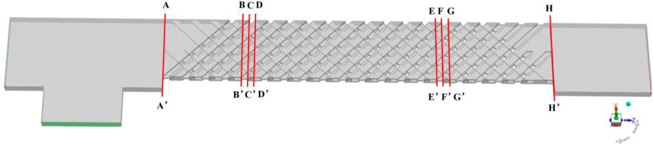
FIGURE 6. Positions of selected x-y planes.
Figures 7, 8 show velocity vectors in the microreactor with three-layer and five-layer inserts on x-y planes at different Re, respectively. The velocity vectors well reveal the mixing principle of splitting and recombination. For the microreactor with three-layer inserts, the two sub-fluids are recombined on the B-B′ plane. Due to the sudden increase in the cross-sectional area, the flow rate slows down, and the residence time extends which provides a longer molecular diffusion time. It is interesting to note that when Re = 0.2, a symmetrical double-saddle-shaped flow structure can be observed on the B-B′ plane, which is beneficial to enhance mixing by stretching and folding the fluid interface (Xia et al., 2005; Viktorov et al., 2015). As the fluid continues to flow and reaches the C-C′ plane, part of the fluid at this cross-section is split and divided into two sub-fluids, while the other part of the fluid is converged into the channel with a narrower cross-sectional area for reorganization. On the D-D′ plane, the flow is reoriented with the change of insert structure. After multiple splitting and recombination cycles, the fluids can be fully mixed. For the microreactor with five-layer inserts, the fluid is also recombined on the B-B′ plane. The biggest difference from the three-layer inserts is that on the C-C ′and D-D′ planes, the fluid is continuously divided into two or three sub-fluids, and no recombination is occurred.
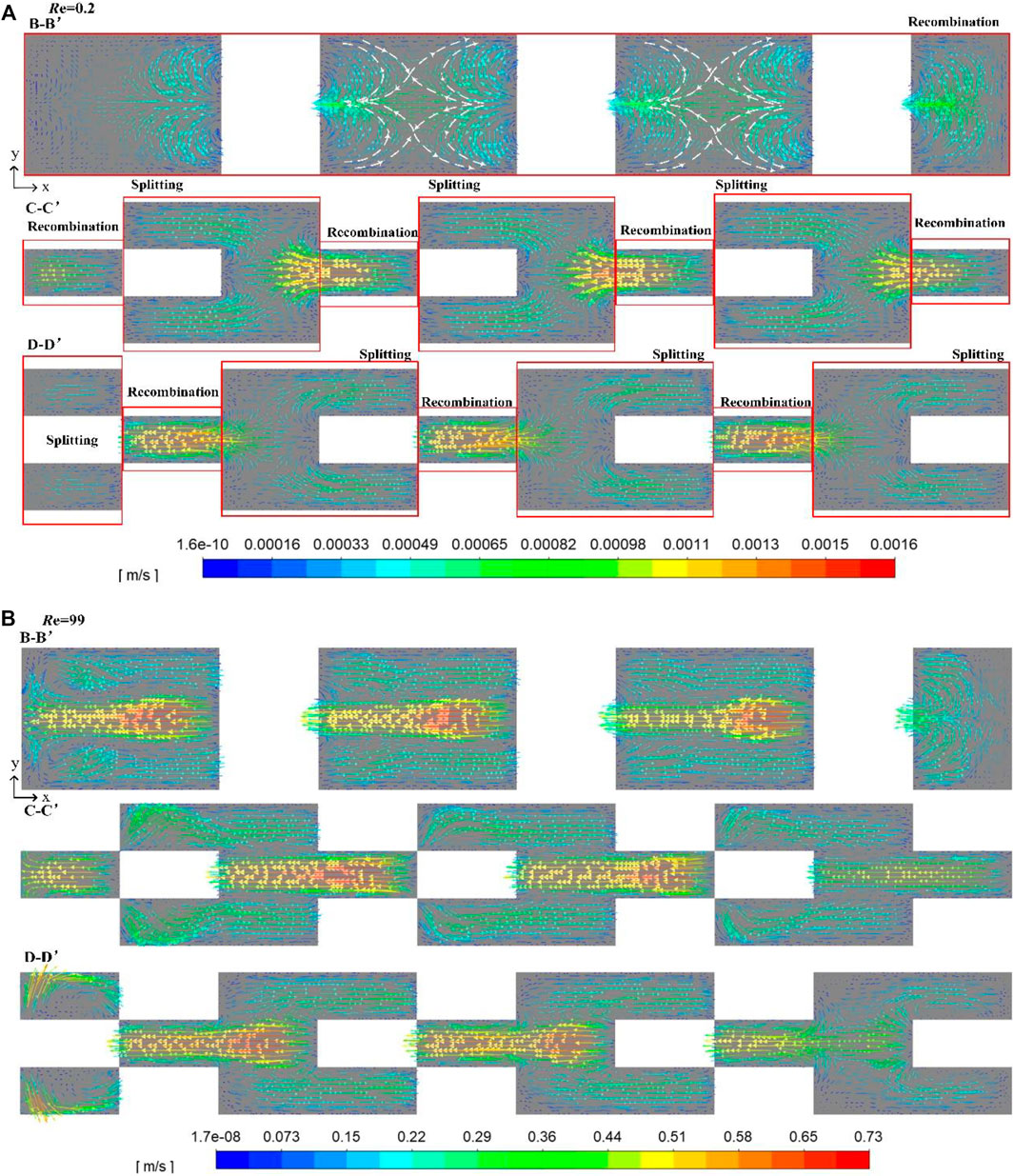
FIGURE 7. Velocity vectors in the microreactor with three-layer inserts on x-y planes: (A) Re = 0.2 and (B) Re = 99.
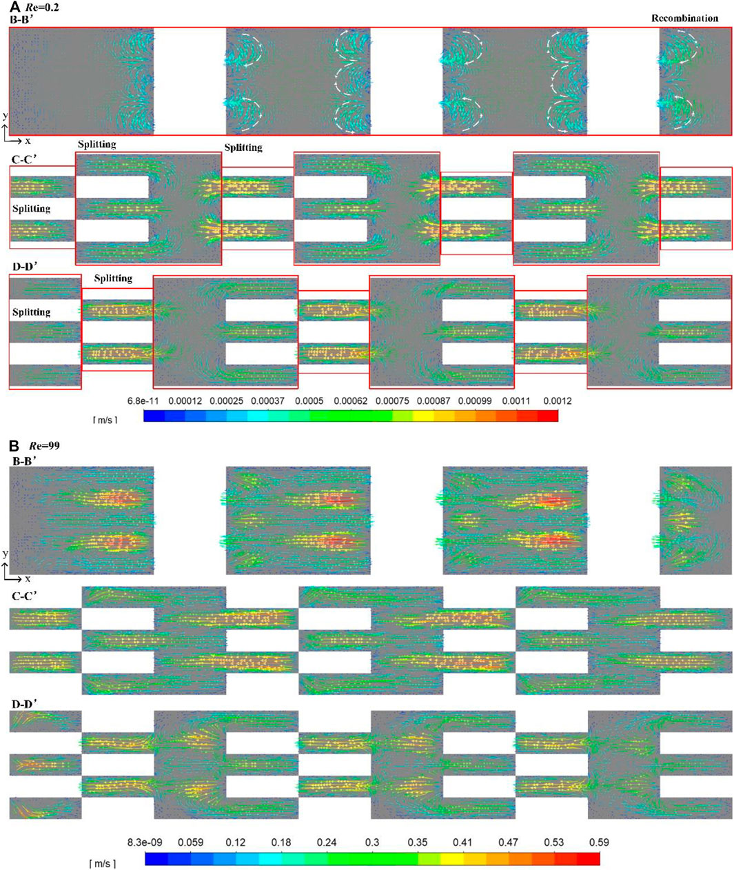
FIGURE 8. Velocity vectors in the microreactor with five-layer inserts on x-y planes: (A) Re = 0.2 and (B) Re = 99.
When Re is 99, for either three-layer or five-layer inserts, there is sufficient contact between different sub-fluids with parallel but opposite velocity direction on the B-B′ plane, which greatly promotes the mixing process.
Figure 9 shows the concentration distribution of water in the microreactor with three-layer and five-layer inserts at Re = 0.2. It can be seen clearly that at the entrance, the two fluids are completely separated, and the mixing process only depends on the molecular diffusion at the interface between the fluids. For the microreactor with three-layer inserts, due to the symmetrical double saddle-shaped flow structure and recombination on the C-C′ and the D-D′ planes, ethanol and water are effectively mixed so that the concentration of water in the plane G-G′ near the outlet is essentially uniform. However, for the microreactor with five-layer inserts, there is no recombination between water and ethanol on the C-C′ and D-D′ planes. Hence, the effect of splitting and recombination is not obvious, and the mixing efficiency is poor.
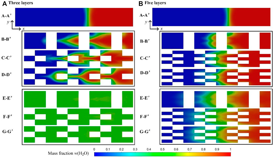
FIGURE 9. Concentration distribution of water on x-y planes at Re = 0.2: (A) three-layer inserts and (B) five-layer inserts.
When Re = 99, in Figure 10, the effect of inertial force is enhanced, and water and ethanol are no longer in a completely separated state, local mixing occurs, and the uniformity of the water concentration distribution is significantly accelerated.
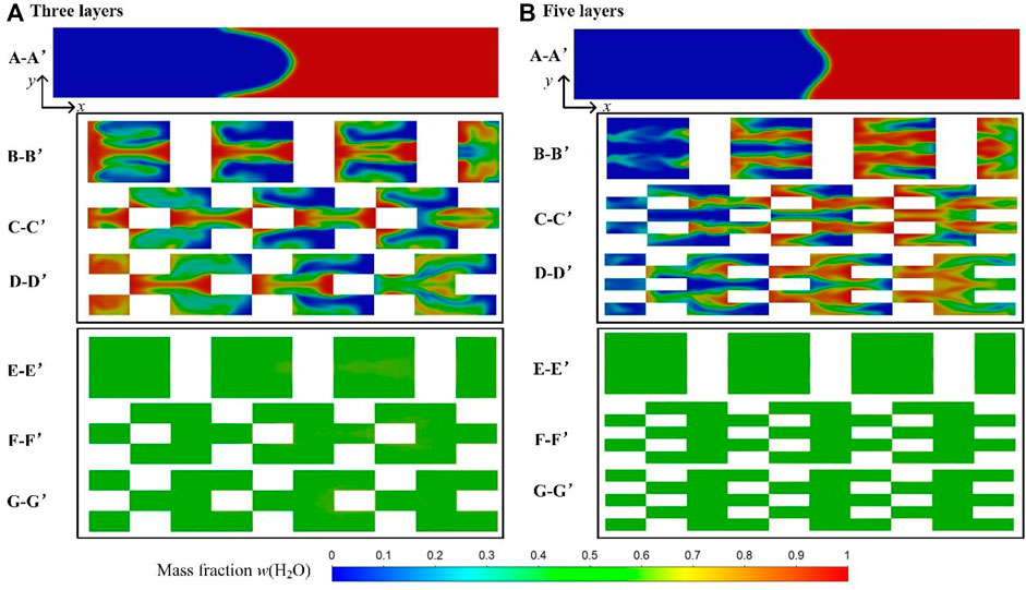
FIGURE 10. Concentration distribution of water on x-y planes at Re = 99: (A) three-layer inserts and (B) five-layer inserts.
3.3 Dimension Parameters of Inserts
The size parameters, s/l and V/H, are selected to investigate the effect of the standard inserts on the mixing process. Figure 11A shows the effect of s/l on the mixing performance at different Re. It can be clearly seen that the ratio of s/l has a significant effect on the mixing performance at low Re (Re ≤ 2). With the increase of s/l from 1 to 4, the mixing efficiency drops from 0.99 to 0.45 at Re = 0.2. When s/l is equal to 1, it is more conducive to improve the mixing performance due to the higher frequency of splitting-and-recombination cycle. While s/l is equal to 4, despite the prolonged diffusion time, the mixing between water and alcohol is poor due to the reduction in the number of splitting-and-recombination cycles (Figure 12). In this range of Re, water and alcohol mixes faster with the increase of Re for s/l = 2, 3, and 4, while the mixing efficiency becomes a litter worse for s/l = 1 with the increase of Re due to the shortened diffusion time. But when Re > 2, vortexes could be better induced in the microreactor and the mixing time is longer. As the case has higher ratio of s/l, the mixing efficiency is greater than that of s/l = 1, as shown in Figure 13.
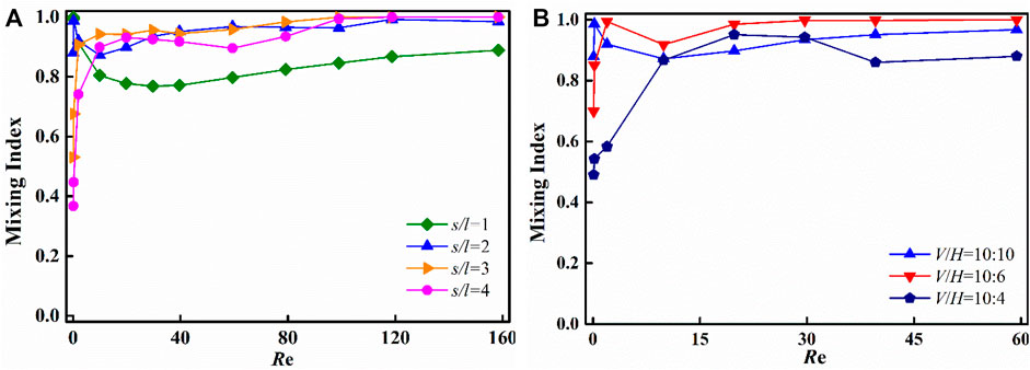
FIGURE 11. Effects of s/l and V/H on mixing performance at different Re: (A) s/l (l = 1 mm, V/H = 10:10, V = 10 mm) and (B) V/H (l = 1 mm, s/l = 2, V = 10 mm).
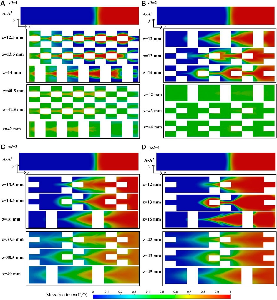
FIGURE 12. Concentration distribution of water on x-y planes with different ratios of s/l at Re = 0.2 (V/H = 10:10, V = 10 mm, l = 1 mm): (A) s/l = 1, (B) s/l = 2, (C) s/l = 3, and (D) s/l = 4.
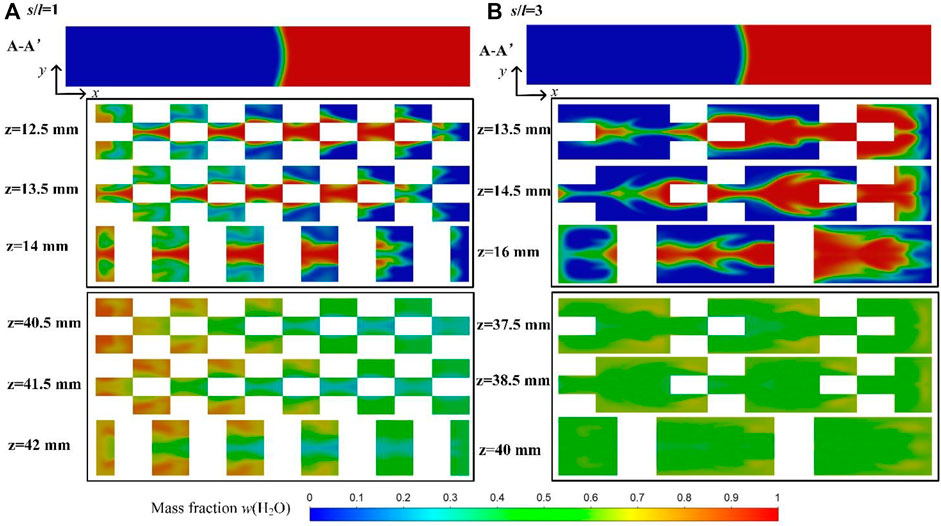
FIGURE 13. Concentration distribution of water on x-y planes with different ratios of s/l at Re = 20 (V/H = 10:10, V = 10 mmL = 1 mm): (A) s/l = 1 and (B) s/l = 3.
The effect of V/H on mixing performance at different Re is shown in Figure 11B. Similarly, the mixing performance is sensitive to the ratio of V/H at low Re number. The higher ratio of V/H is, the worse mixing performance becomes (Figure 14). When the ratio of V/H changes from 10:10 to 10:4, the splitting and recombination cycles reduces, the uniform mixing between different fluids can be hardly achieved.
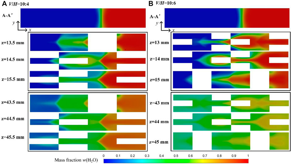
FIGURE 14. Concentration distribution of water on x-y planes with different ratios of V/H at Re = 2 (s/l = 2:1, V = 10 mm, l = 1 mm): (A) V/H = 10:4 and (B) V/H = 10:6.
4 Conclusion
For the purpose of evaluating and improving the mixing performance of the commercial microreactor, a three-dimensional simplified microreactor model based on the principle of splitting and recombination was established, and a systematic numerical study was carried out. The effects of the number of layers and size parameters of the inserts were investigated systematically. Compared with empty rectangular channel, the mixing performance improved significantly with the standard inserts. Meanwhile, the pressure drop increased with the increase of the number of layers. Both the ratio of s/l and V/H were essential for the liquid–liquid mixing process at low Reynolds numbers (Re ≤ 2). With the increase of s/l from 1 to 4, the mixing efficiency dropped from 0.99 to 0.45 at Re = 0.2.
Similarly, the increase in V/H is not beneficial to promote the mixing between fluids. When the ratio of V/H changes from 10:10 to 10:4, the splitting and recombination cycles reduces, the uniform mixing between different fluids can be hardly achieved. Remarkably, the microreactor with three-layer standard inserts (s/l of 2, V/H of 10:10) had the fast mixing rate and excellent mixing efficiency for a wide Reynolds numbers (0.1–160).
Data Availability Statement
The raw data supporting the conclusion of this article will be made available by the authors, without undue reservation.
Author Contributions
LY performed numerical simulations, analyzed the data, and drafted the article. SW helped solve the problems of simulations. YC revised the manuscript many times.
Conflict of Interest
The authors declare that the research was conducted in the absence of any commercial or financial relationships that could be construed as a potential conflict of interest.
Publisher’s Note
All claims expressed in this article are solely those of the authors and do not necessarily represent those of their affiliated organizations, or those of the publisher, the editors, and the reviewers. Any product that may be evaluated in this article, or claim that may be made by its manufacturer, is not guaranteed or endorsed by the publisher.
Acknowledgments
We acknowledge the financial support from the National Natural Science Foundation (No. 21991104, 92034303) and Sinopec Shanghai Research Institute of Petrochemical Technology.
References
Ansari, M. A., and Kim, K.-Y. (2009). A Numerical Study of Mixing in a Microchannel with Circular Mixing chambers. Aiche J. 55 (9), 2217–2225. doi:10.1002/aic.11833
Ansari, M. A., and Kim, K.-Y. (2010). Mixing Performance of Unbalanced Split and Recombine Micomixers with Circular and Rhombic Sub-channels. Chem. Eng. J. 162, 760–767. doi:10.1016/j.cej.2010.05.068
Cai, G., Xue, L., Zhang, H., and Lin, J. (2017). A Review on Micromixers. Micromachines 8 (9), 274–300. doi:10.3390/mi8090274
Chen, Y.-T., Fang, W.-F., Liu, Y.-C., and Yang, J.-T. (2011). Analysis of Chaos and Fret Reaction in Split-And-Recombine Microreactors. Microfluid. Nanofluid. 11, 339–352. doi:10.1007/s10404-011-0803-8
Feng, X., Ren, Y., and Jiang, H. (2013). An Effective Splitting-And-Recombination Micromixer with Self-Rotated Contact Surface for Wide Reynolds Number Range Applications. Biomicrofluidics 7, 54121–54130. doi:10.1063/1.4827598
Gidde, R. R. (2019). On the Computational Analysis of Short Mixing Length Planar Split and Recombine Micromixers for Microfluidic Applications. Int. J. Environ. Anal. Chem. 101 (1), 79–94. doi:10.1080/03067319.2019.1660875
Hao, C., and Meiners, J. C. (2004). Topologic Mixing on a Microfluidic Chip. Appl. Phys. Lett. 84, 2193–2195. doi:10.1063/1.1686895
Hessel, V., Löwe, H., and Schönfeld, F. (2005). Micromixers-a Review on Passive and Active Mixing Principles. Chem. Eng. Sci. 60 (8-9), 2479–2501. doi:10.1016/j.ces.2004.11.033
Hossain, S., Lee, I., Kim, S. M., and Kim, K.-Y. (2017). A Micromixer with Two-Layer Serpentine Crossing Channels Having Excellent Mixing Performance at Low Reynolds Numbers. Chem. Eng. J. 327, 268–277. doi:10.1016/j.cej.2017.06.106
Jensen, K. F. (2017). Flow Chemistry-Microreaction Technology Comes of Age. Aiche J. 63 (3), 858–869. doi:10.1002/aic.15642
Lee, C.-Y., Chang, C.-L., Wang, Y.-N., and Fu, L.-M. (2011). Microfluidic Mixing: A Review. Ijms 12 (5), 3263–3287. doi:10.3390/ijms12053263
Lee, C.-Y., Wang, W.-T., Liu, C.-C., and Fu, L.-M. (2016). Passive Mixers in Microfluidic Systems: A Review. Chem. Eng. J. 288, 146–160. doi:10.1016/j.cej.2015.10.122
Li, P., Cogswell, J., and Faghri, M. (2012). Design and Test of a Passive Planar Labyrinth Micromixer for Rapid Fluid Mixing. Sensors Actuators B: Chem. 174, 126–132. doi:10.1016/j.snb.2012.08.031
Lim, T. W., Son, Y., Jeong, Y. J., Yang, D.-Y., Kong, H.-J., Lee, K.-S., et al. (2011). Three-dimensionally Crossing Manifold Micro-mixer for Fast Mixing in a Short Channel Length. Lab. Chip 11 (1), 100–103. doi:10.1039/c005325m
Lin, Y. (2015). Numerical Characterization of Simple Three-Dimensional Chaotic Micromixers. Chem. Eng. J. 277, 303–311. doi:10.1016/j.cej.2015.04.123
Liu, K., Yang, Q., Chen, F., Zhao, Y., Meng, X., Shan, C., et al. (2015). Design and Analysis of the Cross-Linked Dual Helical Micromixer for Rapid Mixing at Low Reynolds Numbers. Microfluid. Nanofluid. 19, 169–180. doi:10.1007/s10404-015-1558-4
Nguyen, N.-T., and Wu, Z. (2005). Micromixers-a Review. J. Micromech. Microeng. 15, R1–R16. doi:10.1088/0960-1317/15/2/r01
Raza, W., Hossain, S., and Kim, K.-Y. (2018). Effective Mixing in a Short Serpentine Split-And-Recombination Micromixer. Sensors Actuators B: Chem. 258, 381–392. doi:10.1016/j.snb.2017.11.135
Raza, W., and Kim, K.-Y. (2019b). Asymmetrical Split-And-Recombine Micromixer with Baffles. Micromachines 10 (12), 844–859. doi:10.3390/mi10120844
Raza, W., and Kim, K.-Y. (2019a). Unbalanced Split and Recombine Micromixer with Three-Dimensional Steps. Ind. Eng. Chem. Res. 59, 3744–3756. doi:10.1021/acs.iecr.9b00682
Suh, Y. K., and Kang, S. (2010). A Review on Mixing in Microfluidics. Micromachines 1 (3), 82–111. doi:10.3390/mi1030082
Viktorov, V., Mahmud, M., and Visconte, C. (2015). Comparative Analysis of Passive Micromixers at a Wide Range of Reynolds Numbers. Micromachines 6 (8), 1166–1179. doi:10.3390/mi6081166
Ward, K., and Fan, Z. H. (2015). Mixing in Microfluidic Devices and Enhancement Methods. J. Micromech. Microeng. 25 (9), 94001–94017. doi:10.1088/0960-1317/25/9/094001
Xia, H. M., Wan, S. Y. M., Shu, C., and Chew, Y. T. (2005). Chaotic Micromixers Using Two-Layer Crossing Channels to Exhibit Fast Mixing at Low Reynolds Numbers. Lab. Chip 5 (7), 748–755. doi:10.1039/b502031j
Yang, A.-S., Chuang, F.-C., Chen, C.-K., Lee, M.-H., Chen, S.-W., Su, T.-L., et al. (2015). A High-Performance Micromixer Using Three-Dimensional Tesla Structures for Bio-Applications. Chem. Eng. J. 263, 444–451. doi:10.1016/j.cej.2014.11.034
Keywords: microreactor, mixing, inserts, splitting-and-recombination, CFD
Citation: Yan L, Wang S and Cheng Y (2022) Numerical Simulation of Mixing Process in a Splitting-and-Recombination Microreactor. Front. Chem. Eng. 3:803861. doi: 10.3389/fceng.2021.803861
Received: 28 October 2021; Accepted: 14 December 2021;
Published: 10 January 2022.
Edited by:
Frank Gupton, Virginia Commonwealth University, United StatesReviewed by:
Chaoqun Yao, Dalian Institute of Chemical Physics (CAS), ChinaJonathan McDonough, Newcastle University, United Kingdom
Copyright © 2022 Yan, Wang and Cheng. This is an open-access article distributed under the terms of the Creative Commons Attribution License (CC BY). The use, distribution or reproduction in other forums is permitted, provided the original author(s) and the copyright owner(s) are credited and that the original publication in this journal is cited, in accordance with accepted academic practice. No use, distribution or reproduction is permitted which does not comply with these terms.
*Correspondence: Yi Cheng, eWljaGVuZ0B0c2luZ2h1YS5lZHUuY24=