- 1Centro de Investigación, Innovación y Desarrollo de Materiales–CIDEMAT, Universidad de Antioquia, Medellín, Colombia
- 2Department of Chemical Engineering, Imperial College London, London, United Kingdom
Results have been reported previously of a model describing the performance of photoelectrochemical reactors, which utilize semiconductor | liquid junctions. This model was developed and verified using SnIV-doped α-Fe2O3 as photoanodes. Hematite films were fully characterized to obtain parameter inputs to a model predicting photocurrent densities. Thus, measured photocurrents were described and validated by the model in terms of measurable quantities. The complete reactor model, developed in COMSOL Multiphysics, accounted for gas evolution and desorption in the system. Hydrogen fluxes, charge yields and gas collection efficiencies in a photoelectrochemical reactor were estimated, revealing a critical need for geometric optimization to minimize H2-O2 product recombination as well as undesirable spatial distributions of current densities and “overpotentials” across the electrodes. Herein, the model was implemented in a 3D geometry and validated using solid and perforated 0.1 × 0.1 m2 planar photoanodes in an up-scaled photoelectrochemical reactor of 2 dm3. The same model was then applied to a set of simulated electrode geometries and electrode configurations to identify the electrode design that would maximize current densities and H2 fluxes. The electrode geometry was modified by introducing circular perforations of different sizes, relative separations and arrangements into an otherwise solid planar sheet for the purpose of providing ionic shortcuts. We report the simulated effects of electrode thickness and the presence or absence of a membrane to separate oxygen and hydrogen gases. In a reactor incorporating a membrane and a photoanode at 1.51 V vs RHE and pH 13.6, an optimized hydrogen flux was predicted for a perforation geometry with a separation-to-diameter ratio of 4.5 ± 0.5; the optimal perforation diameter was 50 µm. For reactors without a membrane, this ratio was 6.5 and 8.5 for a photoanode in a “wired” (monopolar) and “wireless” (photo-bipolar) design, respectively. The results and methodologies presented here will serve as a framework to optimize composite photoelectrodes (semiconductor | membrane | electrolyte), and photoelectrochemical reactors in general, for the production of hydrogen (and oxygen) from water using solar energy.
Introduction
Thus far, the bulk of the research on photoelectrochemical systems for splitting water with solar energy has focused on material developments (Chen et al., 2010; Tachibana et al., 2012; Moss et al., 2021), aiming to conceive materials that would be: 1) efficient in converting photons to chemical product(s), 2) economical to fabricate and 3) chemically and mechanically durable. These materials are typically synthesized and tested at small scale, with electro-active areas ≤1 cm2 (Khaselev and Turner, 1998; Rocheleau et al., 1998; Kelly and Gibson, 2006; Jia et al., 2016; Bedoya-Lora et al., 2021). Interest in identifying and resolving the many engineering challenges associated with photoelectrochemical device scale-up has been developing through modelling and experiments at a comparatively slower pace (Carver et al., 2012; Haussener et al., 2012; Lopes et al., 2014; Turan et al., 2016; Hankin et al., 2017; Vilanova et al., 2018; Ahmet et al., 2019; Tembhurne et al., 2019; Vilanova et al., 2020).
Engineering challenges apply to four broad types of photoelectrolysis systems, which have emerged:
1. Photovoltaics (PVs) + electrolysers (Kelly et al., 2011; Jia et al., 2016), which are not thermally or chemically integrated with each other and are connected only electronically.
2. Integrated photoelectrochemical devices (IPECs), in which the electrolysis is powered by a solar cell/PV embedded in the device, but in which the PV is either protected from the electrolyte by an interposed layer to prevent photoelectrode corrosion (Reece et al., 2011; Turan et al., 2016) or is integrated with the electrolyser by some other means, such as thermally (Tembhurne et al., 2019).
3. Photoelectrochemical devices (PECs), with semiconductor | liquid junction(s) in which the semiconductor(s) often also function(s) as catalyst (Brillet et al., 2012; Liu et al., 2013; Shaner et al., 2013; Vilanova et al., 2018).
4. Particle-based photocatalytic water splitting devices (PCWS), which are based on a dispersion of one type of particle, or two particles operating in tandem, connected by a redox mediator (Kuang et al., 2016; Wang et al., 2016, 2020; Hisatomi and Domen, 2019).
These systems have sub-classifications based on the finer details of their conceptual design (Nielander et al., 2014). Device designs for systems 1-3 have also been explored and classified schematically to illustrate the wide variety of geometric, electronic and optical configurations that have been conceived to date (Jacobsson et al., 2014; Holmes‐Gentle et al., 2018; Moss et al., 2021).
Looking deeper into the designs of systems 2 and 3, which are the focus of the present study, the electrode arrangements may be “wireless” or “wired” bipolar monoliths or “wired” monopolar photo electrodes in terms electric configurations (Newman, 2013; Berger et al., 2014; Berger and Newman, 2014; Holmes‐Gentle et al., 2018). However, while the focus has been on improving electron/hole transport, the ion transport profiles between electroactive surfaces are also of paramount importance and, if non-uniform, can profoundly affect the reactor performance. Additionally, the usual requirement for “front illumination” (especially for cases when the photoelectrode or PV substrate is not transparent to light or when the charge mobility in the constituent semiconductors are too poor for back-illumination to be appropriate (Eichhorn et al., 2018)) of an embedded PV or semiconductor liquid | junction to maximize the charge separation efficiency can force the hydrogen- and oxygen-evolving electro-active surfaces to face away from each other, also leading to non-uniform electric potential distributions and large ionic transport distances (Hankin et al., 2017; Moss et al., 2021). Two- or three-dimensional (c.f. 1-D) electrical potential distributions in the electrolyte may not affect device performance significantly at the millimeter scale that is relevant to most present spontaneous water splitting tests. However, they become critically important on up-scaling (Newman, 2013; Moss et al., 2021).
Experimental results and multiple models of photoelectrochemical reactors have been produced with emphasis on reactor geometry:
• Models of 1D and 2D reactor geometries (Orazem and Newman, 1984b; Haussener et al., 2012; Berger et al., 2014; Berger and Newman, 2014; Zhang et al., 2020) and 3D reactor geometries (Hankin et al., 2017). A more detailed description of existing models was presented in Part I of this extended study (Bedoya-Lora et al., 2017b).
• Studies of the spatial distributions of electrode kinetics through:
○ Use of louvered photoelectrodes to minimize product cross-over and ohmic losses in neutral and acidic solutions (Haussener et al., 2012; Chen et al., 2014, 2016; Jin et al., 2014; Walczak et al., 2015; Singh et al., 2017),
○ Perforating electrodes to minimize ohmic potential losses (Bosserez et al., 2016; Bedoya-Lora et al., 2017b; Hankin et al., 2017; Trompoukis et al., 2018; Vijselaar et al., 2019).
• Direct experimental validation of model predictions of current density distributions across planar and perforated photoelectrodes in an up-scaled reactor (Ong et al., 2011; Carver et al., 2012; Hankin et al., 2017).
• Simulated and experimentally determined effects of temperature and/or light concentration (Modestino and Haussener, 2015; Tembhurne and Haussener, 2016; Vilanova et al., 2018, 2020; Tembhurne et al., 2019).
Regarding perforated electrodes, minimization of inhomogeneities in spatial distributions of current densities between opposing electroactive surfaces in systems 2 and 3 by means of macro- or microscopic perforations has been proposed conceptually (Orazem and Newman, 1984a; 1984b), validated experimentally, and modelled for wired monopolar PECs (Hankin et al., 2017) and wireless bipolar IPECs (Bosserez et al., 2016; Trompoukis et al., 2018; Vijselaar et al., 2019). Example structures of the perforations, as well as their purpose, are illustrated in Figure 1.
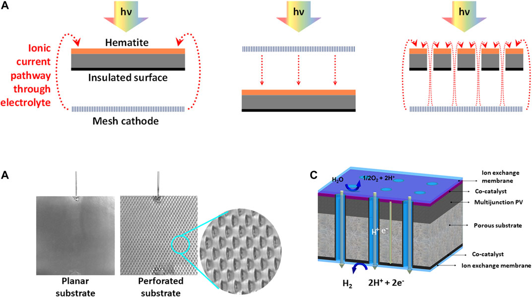
FIGURE 1. Schematic representations of perforations: (A) 2D representation of the relative impacts of (photo)electroactive surface orientations and geometry on the ionic pathlengths, (B) photographic images of the solid and perforated planar Ti substrates used in this study and (C) porous monolithic photoelectrochemical device, reproduced with permission (Trompoukis et al., 2018).
It has been confirmed through experimental data that electrode perforations offer ionic shortcuts through which current density distributions are minimized, but at the same time they also result in H2-O2 cross-over, thereby decreasing hydrogen collection efficiencies (Bosserez et al., 2016). The task at hand now is to demonstrate using a robust photo-electro-kinetic model exactly what the ideal perforation geometry should be that simultaneously 1) maximizes the homogeneity in the current density distribution across the electrode surface and 2) minimizes losses due to H2-O2 crossover. Such a model should necessarily account for efficiencies of gas evolution from the liquid phase (Vogt, 1984) and effects of diffusion of dissolved gas species within a photoelectrochemical reactor. Moreover, the model should enable the prediction of photo-electro-kinetic current densities as a function of operating conditions, such that the current density distributions over electrode surfaces can be modelled; when photocurrents are not predicted in the reactor models, but for simplicity are assigned fixed values, such distributions cannot be modelled accurately. Some of these aspects were addressed in our 2D model of electrode geometry effects in photoelectrochemical reactors (Bedoya-Lora et al., 2017b), as were the effects of photoanode properties on photocurrent densities (Bedoya-Lora et al., 2017a) and theoretical predictions of photocurrent densities using SnIV-doped α-Fe2O3 as an example of photoanodes. In this study we focus specifically on the influence of photoelectrode geometry on photoelectrochemical reactor performance.
Modelling of photoelectrochemical reactors involves a wide range of physics: charge, photon, mass, heat and momentum transfer. Electronic charge and photon transfer have been the focus of most of the models, as these processes are inherently related with the performances and efficiencies of photoelectrode materials (Bedoya-Lora et al., 2021). Electron-hole recombination, absorptivity and band gap are material properties related to both processes. The remaining physics, especially mass and momentum transfer in the context of PEC device design, have been studied to a lesser degree, but are most important for up-scaling of these devices.
The geometrical optimization of perforations using appropriate models for PEC and IPEC systems will be of major importance for the design and up-scaling of photoelectrochemical reactors. Differences in ionic pathlengths across photoelectrode surfaces tend to increase with electrode size, depending on geometry, so giving rise to increasingly inhomogeneous electric potential and current density distributions, that also increase with the magnitudes of (mean) current densities and with ionic resistivities. Hence, it has been suggested that large-scale monolithic photoabsorbers are perhaps not practical and that electrodes should be fabricated from multiple photoabsorber units with dimensions in the range 10−3–10−2 m (Xiang et al., 2016).
Below, we report the performance of a planar and perforated 0.1 × 0.1 m2 Ti | SnIV-doped α-Fe2O3 photoanodes (shown in Figure 1B), accompanied by a simulation-based geometrical optimization of different perforation configurations in the absence and presence of a membrane. In addition to coupling gas bubble (c.f. dissolved gas) formation efficiency and product gas (H2-O2) cross-over, the objective of this paper was to use our model to optimize several PEC geometries and arrangements, including the effects of photon flux densities and electrolyte conductivities. The model can be used to design composite photoelectrodes, fabricated with µm resolution and, for given conditions and photoelectrode properties, optimize geometries of perforations, which cause loss of photoabsorber area, but homogenize spatial distributions of reaction rates. In principle, perforations can be achieved by using an expanded mesh substrate for photoelectrode deposition (Hankin et al., 2017) or, alternatively, laser ablation (Bosserez et al., 2016) or deep reactive etching (Vijselaar et al., 2019) may be used to introduce perforations into pre-formed (photo-)electrodes.
As discussed previously (Bedoya-Lora et al., 2017b), the effects of bubble generation on modelled photocurrent densities have yet to be implemented, incorporating the consequences of light reflection and scattering (Stevens, 2012), coverage of electro-active area (Vogt, 2011; Hernández et al., 2015), ohmic potential losses in the electrolyte (Vogt and Thonstad, 2017), hydrodynamic (Taqieddin et al., 2017) and local convection (Boissonneau and Byrne, 2000). The complex interactions of these factors on the performance of photoelectrochemical reactors is not yet understood adequately (McKone and Lewis, 2013), so their engineering challenges will be discussed in a future publication.
Theoretical Description of Reactor in 3D
Geometry Definitions
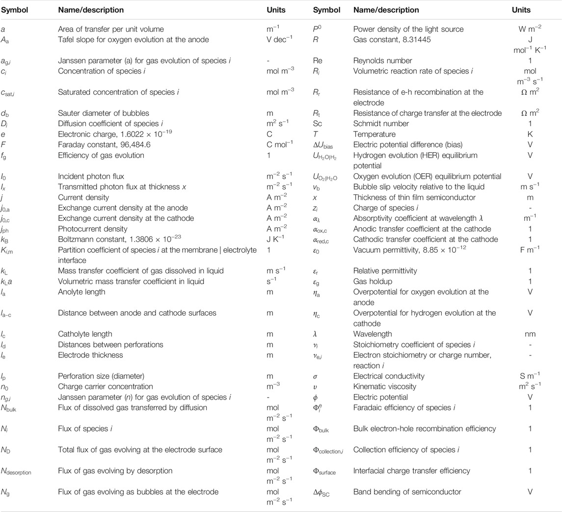
The dimensions and geometry of an existing up-scaled reactor (Hankin et al., 2017) was replicated in a 3D model to predict photocurrent densities and hydrogen fluxes and to enable their comparison with values determined experimentally. All flux densities and current densities were normalized by the geometrical area of the photoanode. A planar photoanode with dimensions 0.1 × 0.1 m2 was exposed to illumination with (photo-electro-) active surface facing away from the cathode, as shown in Figure 2. Hydrogen and oxygen gases were collected in two chambers separated by a cation-permeable Nafion® membrane. This reactor geometry, with illumination of the front of the photoelectrode through the electrolyte, was selected following previous results with better performance than its counterparts with back-illumination and front-illumination through the mesh counter electrode. All the nomenclature referred to in this manuscript is listed in Table 1.
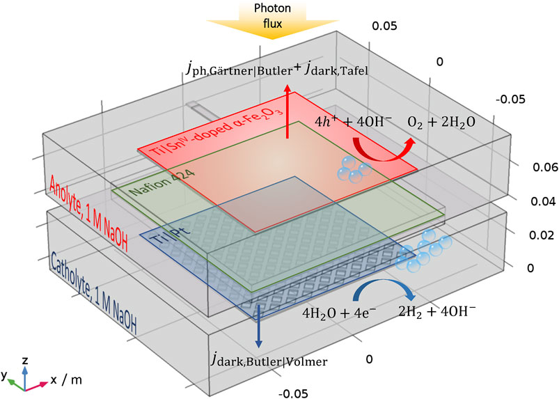
FIGURE 2. Schematic view of the up-scaled photo-electrochemical reactor for model validation. During experiments, the reactor was positioned to allow bubbles to flow under gravity with the y-direction vertical.
A symmetrical 3D model was developed to optimize the photoelectrode geometry with the aim of reducing losses due to ohmic potential drops and cross-over of O2 and H2 products, via perforations and/or membrane. As shown in Figure 3, square and hexagonal distributions of circular perforations were introduced in the planar photoanode structure. The ratio between the separation distance (ld) and diameter (lp) of the perforations, ld/lp, was optimized for several perforation sizes and electrode thicknesses, le. As mentioned previously, to enable rational comparison between the performances with different configurations, all the fluxes and currents densities were calculated with respect to the geometrical area (including perforated area) and not only the electro-active area, as shown in Figure 3A. Furthermore, two electrode arrangements were studied as shown in Figures 3B,C: spatially separated monopolar electrodes (‘wired’) with the photoanode facing away from the cathode and a monolithic photo-bipole (“wireless”) (Newman, 2013). The model with “wired,” front-illuminated photoanodes, Figure 3B, was selected due to its similarities with existing photoelectrochemical cells for material characterisation and scaled-up reactors (Figure 2).
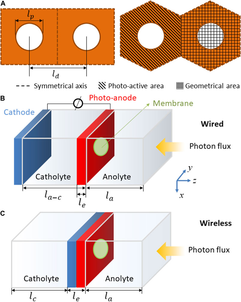
FIGURE 3. (A) Square and hexagonal distributions of perforations in the photo-anode, with lengths and areas defined. Electrode designs for geometrical optimisation: (B) “wired” (photo-anode facing away from cathode) and (C) “wireless” (monolithic photo-bipole) with a single photo-anode.
The distance between electrodes for the wired configuration, la-c, was kept constant at 0.01 m. Other possible configurations, e.g. photoelectrodes separated by perpendicular separators (Haussener et al., 2012) and integrated light-absorber between electrodes (Berger and Newman, 2014) have been investigated. The “wireless” configuration, Figures 3C is possibly the most promising and studied arrangement to date. Several materials and models have been reported using this configuration (Reece et al., 2011; Jin et al., 2014; Bosserez et al., 2016; Vijselaar et al., 2019), although up-scaled reactors have yet to be developed.
Target Definitions
As defined in part I, system performances were evaluated in terms of four parameters: current density (
Experimental
Photoanode Fabrication
0.1 × 0.1 m2 SnIV-doped α-Fe2O3 photoanodes were deposited on titanium by spray pyrolysis, following the procedure reported previously (Bedoya-Lora et al., 2016; Hankin et al., 2017). The electrodes were produced on planar Ti sheets and also on perforated Ti sheets, with rectangular perforations of ca. 3 × 1.5 mm, spaced 5.8 mm horizontally and 2 mm vertically apart. In the present case, photoanodes were not annealed after the deposition of hematite films.
Photoelectrochemical Reactor
Photoelectrochemical measurements were carried out in a photoelectrochemical reactor designed for operation with 0.1 × 0.1 m2 electrodes. The reactor comprised two chambers, each with a volume ≈1 dm3 and separated by a cation-permeable membrane (PTFE-reinforced Nafion® 424, DuPont Inc.), selected for its chemical stability, durability and superior mechanical properties over an anion-permeable counterpart, which otherwise would have been more appropriate for alkaline water splitting. Both compartments were filled with 1 M NaOH (pH 13.6). A potentiostat/galvanostat (Autolab PGSTAT 30) was used to control the reactor with a three-electrode configuration for voltammetry on the photoanode at 50 mV s−1, and a two-electrode configuration for chronoamperometry at an applied cell potential difference of 1.6 V (resulting in a photoanode potential of ≈1.51 V vs RHE) for 24 h. The reason for the two-electrode configuration in the latter case is that the use of a reference electrode did not permit adequate sealing of the reactor for gas evolution rate measurements to be made. Hematite photoanodes acted as working electrodes, platinized titanium mesh (Expanded Metal Company, United Kingdom) as counter electrode and saturated AgCl|Ag as reference electrode (1.001 V vs RHE and 0.197 V vs SHE). The reactor was operated in batch mode without recirculation of electrolyte solution, the hydrodynamic effects of which have yet to be implemented in the model.
A solar simulator (Sun 2000; Abet technologies, United States) with a 550 W Xe arc lamp was used to irradiate the photoanode. The light source was calibrated and mapped at the reactor working distance using a UV-Vis spectrophotometer coupled to a CR2 cosine receptor (Black-Comet CXR-25, StellarNet, United States). An average power density of 433 ± 82 W m−2 was achieved over an area of 0.12 × 0.12 m2 and an estimated 497 ± 12 W m−2 over 0.1 × 0.1 m2, which corresponds to the photoanode area, as shown in Supplementary Figure S1 and S2 in the supporting documentation. An unavoidable degree of non-uniformity in the spatial distribution of the irradiance was evident. The intensity of incoming light was corrected for attenuation by the electrolyte and quartz to give an effective power density of 461 W m−2 over the photoanode surface.
Photoelectrochemical properties of un-annealed Ti | SnIV-doped α-Fe2O3 have been measured previously using a small photoelectrochemical cell (0.06 dm3) and an electroactive area of 3 × 6 mm2. As discussed in the next section, parameters from experimental results reported previously (Bedoya-Lora et al., 2017b) were also employed in the model described below after correction for any changes in the power density delivered by the light source. The average absorbed photon flux for the photoanode is presented in Supplementary Figure S3 in the supporting information.
Voltammograms were obtained over a sufficiently short time period for electrolyte temperatures to remain constant at 25 C. As shown in Supplementary Figure S4 in the supporting documentation, prolonged illumination caused electrolyte temperatures to rise to ca. 40 C within the first ca. 6 h, after which thermal equilibrium with surroundings was achieved. Hence, chronoamperometry results are not shown for this initial 6-h period. Gas flow rates for cathode (hydrogen) and anode (oxygen) compartments were recorded by gas flow meters (MilliGascounter MGC-1, Ritter, Germany) during longer term (24 h) chronoamperometry; the steady state temperature was used to correct molar flux densities, assuming ideal gas behavior.
Software
Comsol Multiphysics 5.2a with a Batteries and Fuel Cells module was used to solve the system of equations using the finite element method. Secondary current distribution (siec) and transport of diluted species (tds) physics were coupled; gas desorption was treated as a homogeneous reaction in the bulk of the electrolyte. A stationary non-linear solver was used, typically with a relative tolerance of 0.001 and a maximum of 50 iterations; the suitability of these parameters has been reported previously (Hankin et al., 2017).
The mesh of the up-scaled reactor was geometry-dependent with a minimum element size of 3.33 × 10⁻³ m and maximum size of 0.02 m. The mesh was optimized for higher resolutions in narrow regions. The model converged typically in under 3 min for a given set of conditions. In the case of models for geometric optimization, a minimum element size of 8 × 10⁻⁷ m and maximum size of 8 × 10⁻⁴ m was used. The model converged usually in under 10 s. A parametric sweep was used to evaluate a wide range of settings and geometries.
Preliminary Considerations
Effects of the Temperature on the Performance of the Cell
Efficiencies of hydrogen bubble formation,
Concentrations of dissolved oxygen and hydrogen at saturation were interpolated from published experimental data (Shoor, 1968) for KOH solutions at different temperatures and concentrations. Values estimated at 25 C using these experimental data were remarkably similar to more recent values determined for this temperature (Davis et al., 1967; Joe et al., 1988; Tromans, 1998), so it was assumed that interpolations at 40 C and 1 M KOH were sufficiently reliable to be used in the model. In contrast to oxygen, it was found that hydrogen solubility decreased only slightly with temperature, offering an explanation of why
The effects of the change in temperature, from 25 to 40 C, on the properties of the semiconductor (SnIV-doped α-Fe2O3) were considered too small to merit consideration in this particular study. Also, the effect of temperature on membrane properties were disregarded due to the lack of data available for the conditions and materials assessed in this work.
Photon Flux Distribution of Solar Simulator
As discussed and demonstrated earlier, the photon flux delivered by the solar simulator was not radially uniform across the photoanode surface. This non-uniformity was a potential concern, as it can cause a significant distribution in “overpotentials” and photocurrent densities across a 0.1 × 0.1 m2 electrode. The photon flux density was evaluated as a function of position on the photoanode surface,
Results and Discussion
3D Up-Scaled Reactor Model
The predicted photocurrent densities as a function of potential in the up-scaled reactor using 0.1 × 0.1 m2 planar and perforated electrodes were within the error of experimental measurement (Supplementary Figure S6), as confirmed in an earlier version of the model (Hankin et al., 2017).
Hydrogen and oxygen fluxes were measured and estimated after operating the reactor at 1.6 V cell potential difference, which corresponded to ca. +1.51 V vs RHE at the anode. During the first ca. 6 h, H2 and O2 fluxes were not stable and produced non-stoichiometric yields due to a combination of heating of the system and gradual saturation of catholyte and anolyte with gases. The generated volumes of both gases were recorded over time during these experiments and are reported in Supplementary Figure S7. Reactor performance was relatively stable after 10 h of operation. As shown in Supplementary Figure S8, predicted current densities and fluxes of hydrogen and oxygen agreed with experimental data after 10 h of photoelectrolysis. The molar ratio between evolving gases, H2:O2, oscillated between 2.3 and 2.0, in agreement with electron stoichiometries of the cathodic and anodic reactions (Supplementary Figure S9); values of H2:O2 above and below 2.0 may have been caused by oxygen leaking from the anolyte, due to imperfect sealing around the membrane and quartz window, and lower precision of the gas flow meters in measuring slower rates of oxygen evolution compared to hydrogen evolution. Charge yields for the planar electrode were ca. 0.9 and 0.8 for hydrogen and oxygen evolution, respectively. In the case of the perforated photo anode, charge yields oscillated between 0.9 and 1.0 for both oxygen and hydrogen. However, the predicted value for this parameter according to the model should have been close to unity (0.99). Again, the deviation of experimental data from model predictions was probably associated with non-steady state operation and leaking of gases during prolonged experiments. However, the agreement of the model with experimental results was still very good.
Current densities at the center of a planar photo anode (Supplementary Figure S10) were higher than at the edges due to the non-uniform illumination associated with the light source (Supplementary Figure S5). However, the predicted “overpotential” (
According to model predictions, steady state oxygen concentrations reached supersaturation in the anolyte chamber adjacent to the photoanode surface, with analogous behaviour for hydrogen in the catholyte. Consequently, the flux of dissolved gases through the compartments was small and was minimized effectively when a membrane was present (Supplementary Figure S11). This also implies that significant gas desorption rates were operative only near electrode surfaces (<10 mm), as shown in Supplementary Figure S12. Although small fluxes of dissolved gas were predicted to occur through the perforations, even in the absence of a membrane, their magnitude was not sufficient to affect model predictions, which corresponded to O2 and H2 collection efficiencies of ca. 0.99. In contrast, experimentally determined values of 0.8 suggested potential leakage of gases through the membrane seals (nitrile rubber) of the reactor.
3D (Symmetrical) Model Optimization
An un-annealed Ti | SnIV-doped α-Fe2O3 photo-anode in 1 M NaOH at 25 C and at a potential of 1.51 V vs RHE was modelled under illumination by 1.5AM light; properties are presented in Supplementary Tables S5, S7 and S8 (Frossling, 1938; Powell and Tye, 1961; Marrucci and Nicodemo, 1967; Ogumi et al., 1985; Joe et al., 1988; Sone et al., 1996; Haug and White, 2000; Painmanakul et al., 2009; Sheng et al., 2010; ASTM G173-03, 2012; Lee, 2013). A Ti | Pt cathode was used in 1 M NaOH electrolyte solution. Nafion® 117 was used in some cases as membrane and for filling the perforations in the photoanode throughout its thickness, which was assumed initially as 500 µm. As shown schematically in Figure 3, this model was used to predict values for the ratio between perforation separation/size,
Hexagonal vs square perforation distributions: the effects of spatial distributions of perforations on current densities and hydrogen fluxes for a “wired” reactor configuration without the perforations being filled with a membrane, are presented in Supplementary Figures S13 and S14. There was no difference between squared and hexagonal distributions, when current densities and hydrogen fluxes were plotted as functions of the ratio between the active and geometrical area. When plotted as a function of
For
Optimized
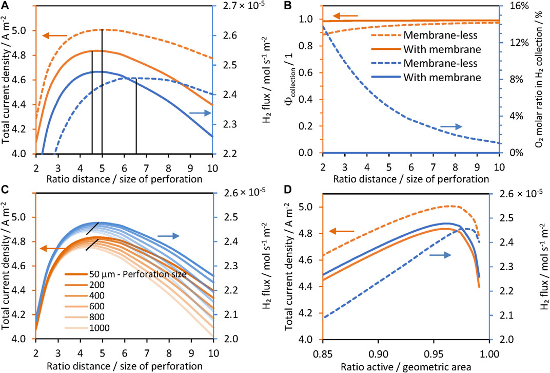
FIGURE 4. Effect of the separation/size ratio of perforations in a hexagonal arrangement, ld/lp, for a ‘wired’ reactor: Ti | Pt| 1 M NaOH | SnIV-doped α-Fe2O3 | Ti, without a membrane (dashed) and with a membrane (solid), photo-anode at 1.51 V vs RHE. (A) Current densities and hydrogen fluxes for lp = 50 μm. (B) Collection efficiencies and concentration of O2 collected in the catholyte. (C) Current densities and hydrogen flux densities for different perforation sizes, and (D) current densities and hydrogen flux densities as a function of the ratio of active and geometric areas.
In contrast, Figure 4A also shows that optimum hydrogen fluxes reached similar values of ca. 2.45 × 10⁻⁵ mol m−2 s−1 with or without a membrane at different
Figure 5 shows that higher current densities can be achieved without using a membrane, but a higher concentration of oxygen (above saturation concentration) was found in the catholyte. The membrane effectively separated hydrogen and oxygen gases, and concentrations were almost identical for low and higher values of
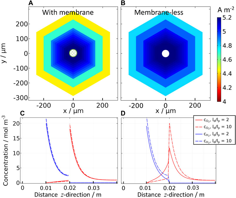
FIGURE 5. Effect of inter-perforation distance (ld) on current densities for “wired” reactor: Ti | Pt | 1 M NaOH | SnIV-doped α-Fe2O3 | Ti, (A) with and (B) without a membrane; photoanode at 1.51 V vs RHE with a perforation size of lp = 50 μm, ld/lp = 2 to 10; and concentration profiles of oxygen and hydrogen for the same ‘wired’ reactor (C) with and (D) without a membrane in the z-direction in the center of the perforation (x = 0, y = 0) for ld/lp = 2 and 10.
Optimized
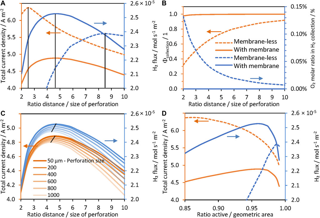
FIGURE 6. Effect of the separation/size of perforation ratio in a hexagonal arrangement, ld/lp, on current densities for “wireless” (photo-bipolar) reactor, 1 M NaOH | Pt | Ti | SnIV-doped α-Fe2O3 | 1 M NaOH with (solid lines) and without (dashed lines) a membrane, photoanode at 1.51 V vs RHE. (A) Current densities and hydrogen fluxes for perforation size lp = 50 μm. (B) Collection efficiencies and amounts of O2 collected in the catholyte. (C) Current densities and hydrogen fluxes for different perforation sizes, and (D) current densities and hydrogen fluxes as a function of the ratio of active and geometric areas.
This was confirmed by predictions shown in Figure 7, in which concentrations of oxygen and hydrogen in the catholyte and anolyte, respectively, were near zero. Despite the lack of oxygen found in the gas collected from the cathode compartment, collection efficiencies of a membrane-less and “wireless” system decreased greatly for low values of
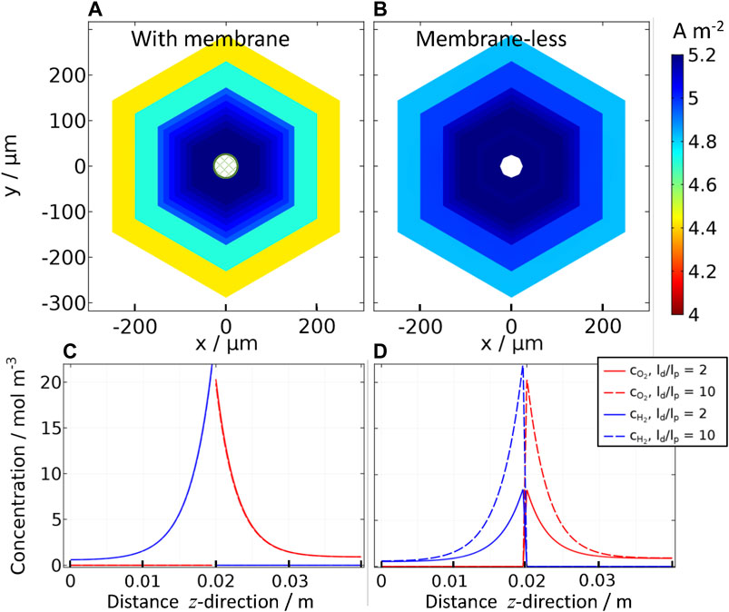
FIGURE 7. Effect of inter-perforation distance (ld) on current densities for “wireless” (photo-bipolar) reactor (A) with and (B) without a membrane, with 1 M NaOH | Pt | Ti | SnIV-doped α-Fe2O3 | 1 M NaOH, photoanode at 1.51 V vs RHE with a perforation size of lp = 50 μm, ld/lp = 2 to 10; and concentration profiles of oxygen and hydrogen for the same “wireless” reactor (C) with and (D) without a membrane in the z-direction (i.e. through catholyte | membrane (z = 0.02 m)| anolyte) in the center of the perforation (x = 0, y = 0) for ld/lp = 2 and 10.
The optimum geometry did not change significantly on increasing perforation sizes (lp), but the total current density and net hydrogen fluxes decreased, due to loss of photoactive area, as implied by data in Figure 6C; hence, perforations <200 µm are preferred. Bosserez et al. performed a similar experimental study using perforated monoliths (“wireless” configuration without a membrane, using n-Si as photo-absorber and Pt and IrO2 as catalyst films for H2 and O2 evolution, respectively (Bosserez et al., 2016)) aiming to minimize ohmic potential losses using different sizes and distances between perforations, for
As shown in Figure 7, in the presence of a membrane, there was no difference between the hydrogen and oxygen concentration profiles at low and high
Figures 7A,B also show that current densities for different
Sensitivity Analysis
The effects on hydrogen fluxes were predicted by varying the following parameters: semiconductor donor density (1024–1027 m−3), irradiance (10−1–102 suns), electrode thickness (0.1–3 mm) and electrolyte conductivity (10−1–102 S m−1). For each range of variables, the relative optimum hydrogen fluxes were defined as a function of
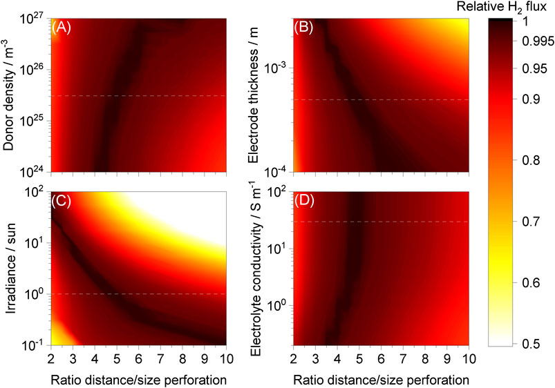
FIGURE 8. Hydrogen fluxes relative to maxima achieved as a function of ld/lp for different ranges of (A) donor density, (B) electrode thickness, (C) irradiance and (D) electrolyte conductivity while keeping other parameters unchanged. “Wired” Ti | Pt| 1 M NaOH | SnIV-doped α-Fe2O3 | Ti with and without a membrane, photo-anode at 1.51 V vs RHE. Dashed white lines represent typical values used in the model.
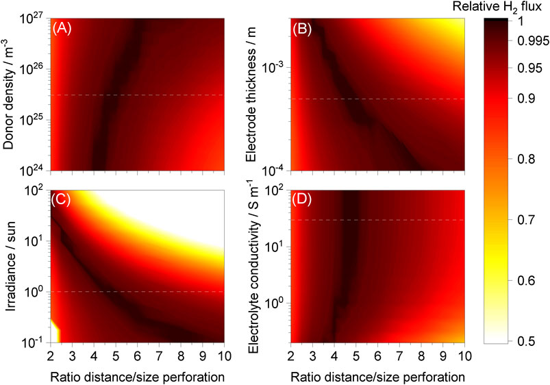
FIGURE 9. Hydrogen fluxes relative to maxima achieved as a function of ld/lp for different ranges of (A) donor density, (B) electrode thickness, (C) irradiance and (D) electrolyte conductivity while keeping the other parameters unchanged. “Wireless” reactor, 1 M NaOH | Pt | Ti | SnIV-doped α-Fe2O3 | 1 M NaOH with photo-anode at 1.51 V vs RHE and a hexagonal array of perforations. Dashed white lines represent typical values used in the model.
The effect of electrode thickness, increasing ohmic potential losses, was expected and comparable to results reported previously (Bosserez et al., 2016). When the perforation diameter/area was smaller while maintaining the same electrode thickness,
On the other hand, optima for donor density and electrolyte conductivity were near the same
Conclusion
A model was developed in terms of measurable properties of the photoelectrode (donor density, photon absorption, bulk and interfacial electron-hole efficiencies, flat band, thickness, exchange current density and Tafel slope), spectrally resolved photon flux of the light source, volumetric mass transfer for gas desorption, bubble formation of hydrogen and oxygen at the electrode surface, and the presence or absence of a membrane between electrodes. The model was validated successfully against experimental data obtained from an up-scaled reactor using a 0.1 × 0.1 m2 photoanode, SnIV-doped α-Fe2O3 spray pyrolysed on titanium. Different reactor designs, parameter values and geometries were studied and optimized as a function of current densities, hydrogen fluxes and collection efficiencies, accounting for H2-O2 cross-over, ohmic potential losses and current density distributions. Optimal ratios of separation to size of perforations were found for a wide range of geometrical configurations and photoanode properties. The effects of temperature were considered to a limited extent, but a deeper understanding of its effects on the photoanode performance should be addressed, as well as the inclusion of convection effects (or flow) on bubble efficiency and H2-O2 crossover rates.
The model predictions emphasized the importance of using a membrane for quiescent electrolytes, especially when a “wireless” photo-bipolar reactor design is used. Hydrogen fluxes for “wired” and “wireless” reactor configurations were comparable when a membrane was incorporated. By contrast, in the absence of a membrane, the model predicted significant H2 and O2 cross-over for a ‘wired’ system, while “wireless” systems exhibited low charge yields for the range of parameters evaluated in the photoelectrochemical model.
Data Availability Statement
The raw data supporting the conclusions of this article will be made available by the authors, without undue reservation.
Author Contributions
FB made substantial contributions to the conception of the work, to the acquisition, analysis and interpretation of data for the work, as well as writing the manuscript. AH contributed significantly to the model formulation and to the production of the manuscript. GK was the project leader.
Conflict of Interest
The authors declare that the research was conducted in the absence of any commercial or financial relationships that could be construed as a potential conflict of interest.
Publisher’s Note
All claims expressed in this article are solely those of the authors and do not necessarily represent those of their affiliated organizations, or those of the publisher, the editors and the reviewers. Any product that may be evaluated in this article, or claim that may be made by its manufacturer, is not guaranteed or endorsed by the publisher.
Acknowledgments
The authors thank Royal Dutch Shell and the UK Engineering and Physical Sciences Research Council for a postdoctoral research associateship for AH and FB, and the Colombian Government for a COLCIENCIAS scholarship 568 for PhD studies abroad for FB.
Supplementary Material
The Supplementary Material for this article can be found online at: https://www.frontiersin.org/articles/10.3389/fceng.2021.749058/full#supplementary-material
References
Ahmet, I. Y., Ma, Y., Jang, J.-W., Henschel, T., Stannowski, B., Lopes, T., et al. (2019). Demonstration of a 50 Cm2 BiVO4 Tandem Photoelectrochemical-Photovoltaic Water Splitting Device. Sust. Energ. Fuels 3, 2366–2379. doi:10.1039/c9se00246d
ASTM G173-03 (2012). Standard Tables for Reference Solar Spectral Irradiances: Direct Normal and Hemispherical on 37° Tilted Surface. ASTM International.
Bedoya-Lora, F., Hankin, A., and Kelsall, G. H. (2016). Photo-electrochemical Hydrogen Sulfide Splitting Using Sn IV -doped Hematite Photo-Anodes. Electrochemistry Commun. 68, 19–22. Available at: http://www.sciencedirect.com/science/article/pii/S1388248116300856. doi:10.1016/j.elecom.2016.04.010
Bedoya-Lora, F. E., Hankin, A., Holmes-Gentle, I., Regoutz, A., Nania, M., Payne, D. J., et al. (2017a). Effects of Low Temperature Annealing on the Photo-Electrochemical Performance of Tin-Doped Hematite Photo-Anodes. Electrochimica Acta 251, 1–11. Available at: http://www.sciencedirect.com/science/article/pii/S0013468617317310. doi:10.1016/j.electacta.2017.08.090
Bedoya-Lora, F. E., Hankin, A., and Kelsall, G. H. (2017b). En Route to a Unified Model for Photo-Electrochemical Reactor Optimisation. I - Photocurrent and H2 Yield Predictions. J. Mater. Chem. A. 5, 22683–22696. doi:10.1039/c7ta05125e
Bedoya-Lora, F. E., Holmes-Gentle, I., and Hankin, A. (2021). Electrochemical Techniques for Photoelectrode Characterisation. Curr. Opin. Green Sust. Chem. 29, 100463. doi:10.1016/j.cogsc.2021.100463
Berger, A., and Newman, J. (2014). An Integrated 1-Dimensional Model of a Photoelectrochemical Cell for Water Splitting. J. Electrochem. Soc. 161, E3328–E3340. doi:10.1149/2.035408jes
Berger, A., Segalman, R. A., and Newman, J. (2014). Material Requirements for Membrane Separators in a Water-Splitting Photoelectrochemical Cell. Energy Environ. Sci. 7, 1468–1476. doi:10.1039/c3ee43807d
Boissonneau, P., and Byrne, P. (2000). An Experimental Investigation of Bubble-Induced Free Convection in a Small Electrochemical Cell. J. Appl. Electrochemistry 30, 767–775. doi:10.1023/a:1004034807331
Bosserez, T., Geerts, L., Rongé, J., Ceyssens, F., Haussener, S., Puers, R., et al. (2016). Minimization of Ionic Transport Resistance in Porous Monoliths for Application in Integrated Solar Water Splitting Devices. J. Phys. Chem. C 120, 21242–21247. doi:10.1021/acs.jpcc.6b06766
Brillet, J., Yum, J.-H., Cornuz, M., Hisatomi, T., Solarska, R., Augustynski, J., et al. (2012). Highly Efficient Water Splitting by a Dual-Absorber Tandem Cell. Nat. Photon 6, 824–828. doi:10.1038/nphoton.2012.265
Carver, C., Ulissi, Z., Ong, C. K., Dennison, S., Kelsall, G. H., and Hellgardt, K. (2012). Modelling and Development of Photoelectrochemical Reactor for H2 Production. Int. J. Hydrogen Energ. 37, 2911–2923. doi:10.1016/j.ijhydene.2011.07.012
Chen, Z., Jaramillo, T. F., Deutsch, T. G., Kleiman-Shwarsctein, A., Forman, A. J., Gaillard, N., et al. (2010). Accelerating Materials Development for Photoelectrochemical Hydrogen Production: Standards for Methods, Definitions, and Reporting Protocols. J. Mater. Res. 25, 3–16. doi:10.1557/jmr.2010.0020
Chen, Y., Xiang, C., Hu, S., and Lewis, N. S. (2014). Modeling the Performance of an Integrated Photoelectrolysis System with 10 × Solar Concentrators. J. Electrochem. Soc. 161, F1101–F1110. F1110. doi:10.1149/2.0751410jes
Chen, Y., Lewis, N. S., and Xiang, C. (2016). Modeling and Simulation of the Spatial and Light-Intensity Dependence of Product Distributions in an Integrated Photoelectrochemical CO2 Reduction System. ACS Energ. Lett. 1, 273–280. doi:10.1021/acsenergylett.6b00134
Davis, R. E., Horvath, G. L., and Tobias, C. W. (1967). The Solubility and Diffusion Coefficient of Oxygen in Potassium Hydroxide Solutions. Electrochimica Acta 12, 287–297. doi:10.1016/0013-4686(67)80007-0
Eichhorn, J., Kastl, C., Cooper, J. K., Ziegler, D., Schwartzberg, A. M., Sharp, I. D., et al. (2018). Nanoscale Imaging of Charge Carrier Transport in Water Splitting Photoanodes. Nat. Commun. 9, 2597. doi:10.1038/s41467-018-04856-8
Frossling, N. (1938). Uber die Verdunstung Fallender Tropfen (The Evaporation of Falling Drops). Gerlands Beitrage zur Geophys. 52, 107–216.
Hankin, A., Bedoya-Lora, F. E., Ong, C. K., Alexander, J. C., Petter, F., and Kelsall, G. H. (2017). From Millimetres to Metres: the Critical Role of Current Density Distributions in Photo-Electrochemical Reactor Design. Energ. Environ. Sci. 10, 346–360. doi:10.1039/c6ee03036j
Haug, A. T., and White, R. E. (2000). Oxygen Diffusion Coefficient and Solubility in a New Proton Exchange Membrane. J. Electrochem. Soc. 147, 980–983. doi:10.1149/1.1393300
Haussener, S., Xiang, C., Spurgeon, J. M., Ardo, S., Lewis, N. S., and Weber, A. Z. (2012). Modeling, Simulation, and Design Criteria for Photoelectrochemical Water-Splitting Systems. Energ. Environ. Sci. 5, 9922–9935. doi:10.1039/c2ee23187e
Hernández, S., Barbero, G., Saracco, G., and Alexe-Ionescu, A. L. (2015). Considerations on Oxygen Bubble Formation and Evolution on BiVO4 Porous Anodes Used in Water Splitting Photoelectrochemical Cells. J. Phys. Chem. C 119, 9916–9925. doi:10.1021/acs.jpcc.5b01635
Hisatomi, T., and Domen, K. (2019). Reaction Systems for Solar Hydrogen Production via Water Splitting with Particulate Semiconductor Photocatalysts. Nat. Catal. 2, 387–399. doi:10.1038/s41929-019-0242-6
Holmes‐Gentle, I., Alhersh, F., Bedoya‐Lora, F., and Hellgardt, K. (2018). “Photoelectrochemical Solar Cells,” in “Photoelectrochemical Reaction Engineering for Solar Fuels Production,” in Photoelectrochemical Solar Cells. Editors N. D. Sankir, and M. Sankir (John Wiley & Sons), 1–41. doi:10.1002/9781119460008
Jacobsson, T. J., Fjällström, V., Edoff, M., and Edvinsson, T. (2014). Sustainable Solar Hydrogen Production: from Photoelectrochemical Cells to PV-Electrolyzers and Back Again. Energ. Environ. Sci. 7, 2056–2070. doi:10.1039/c4ee00754a
McKone, J., and Lewis, N. (2013). “CHAPTER 3. Structured Materials for Photoelectrochemical Water Splitting,” in Photoelectrochemical Water Splitting: Materials, Processes and Architectures Energy and Environment Series (Cambridge, UK: The Royal Society of Chemistry), 52, 52–82. doi:10.1039/9781849737739-00052
Jia, J., Seitz, L. C., Benck, J. D., Huo, Y., Chen, Y., Ng, J. W., et al. (2016). Solar Water Splitting by Photovoltaic-Electrolysis with a Solar-To-Hydrogen Efficiency over 30. Nat. Commun. 7, 13237. doi:10.1038/ncomms13237
Jin, J., Walczak, K., Singh, M. R., Karp, C., Lewis, N. S., and Xiang, C. (2014). An Experimental and Modeling/simulation-Based Evaluation of the Efficiency and Operational Performance Characteristics of an Integrated, Membrane-free, Neutral pH Solar-Driven Water-Splitting System. Energ. Environ. Sci. 7, 3371–3380. doi:10.1039/c4ee01824a
Chin Kwie Joe, J. M., Janssen, L. J. J., van Strelen, S. J. D., Verbunt, J. H. G., and Sluyter, W. M. (1988). Bubble Parameters and Efficiency of Gas Bubble Evolution for a Chlorine-, a Hydrogen- and an Oxygen-Evolving Wire Electrode. Electrochimica Acta 33, 769–779. doi:10.1016/s0013-4686(98)80006-6
Joshi, J. B., and Sharma, M. M. (1979). A Circulation Cell Model for Bubble Columns. Transaction Inst. Chem. Eng. 57, 244–251. doi:10.1002/cjce.5450570321
Kelly, N., and Gibson, T. (2006). Design and Characterization of a Robust Photoelectrochemical Device to Generate Hydrogen Using Solar Water Splitting. Int. J. Hydrogen Energ. 31, 1658–1673. doi:10.1016/j.ijhydene.2005.12.014
Kelly, N. A., Gibson, T. L., and Ouwerkerk, D. B. (2011). Generation of High-Pressure Hydrogen for Fuel Cell Electric Vehicles Using Photovoltaic-Powered Water Electrolysis. Int. J. Hydrogen Energ. 36, 15803–15825. doi:10.1016/j.ijhydene.2011.08.058
Khaselev, O., and Turner, J. A. (1998). A Monolithic Photovoltaic-Photoelectrochemical Device for Hydrogen Production via Water Splitting. Science 280, 425–427. doi:10.1126/science.280.5362.425
Kuang, Y., Jia, Q., Ma, G., Hisatomi, T., Minegishi, T., Nishiyama, H., et al. (2016). Ultrastable Low-Bias Water Splitting Photoanodes via Photocorrosion Inhibition and In Situ Catalyst Regeneration. Nat. Energ. 2, 16191. doi:10.1038/nenergy.2016.191
Lee, S. H. (2013). Molecular Dynamics Simulation Study for Hydroxide Ion in Supercritical Water Using SPC/E Water Potential. Bull. Korean Chem. Soc. 34, 2925–2930. doi:10.5012/bkcs.2013.34.10.2925
Liu, C., Tang, J., Chen, H. M., Liu, B., and Yang, P. (2013). A Fully Integrated Nanosystem of Semiconductor Nanowires for Direct Solar Water Splitting. Nano Lett. 13, 2989–2992. doi:10.1021/nl401615t
Lopes, T., Dias, P., Andrade, L., and Mendes, A. (2014). An Innovative Photoelectrochemical Lab Device for Solar Water Splitting. Solar Energ. Mater. Solar Cell 128, 399–410. doi:10.1016/j.solmat.2014.05.051
Marrucci, G., and Nicodemo, L. (1967). Coalescence of Gas Bubbles in Aqueous Solutions of Inorganic Electrolytes. Chem. Eng. Sci. 22, 1257–1265. doi:10.1016/0009-2509(67)80190-8
McGinnis, D. F., and Little, J. C. (2002). Predicting Diffused-Bubble Oxygen Transfer Rate Using the Discrete-Bubble Model. Water Res. 36, 4627–4635. doi:10.1016/s0043-1354(02)00175-6
Modestino, M. A., and Haussener, S. (2015). An Integrated Device View on Photo-Electrochemical Solar-Hydrogen Generation. Annu. Rev. Chem. Biomol. Eng. 6, 13–34. doi:10.1146/annurev-chembioeng-061114-123357
Moss, B., Babacan, O., Kafizas, A., and Hankin, A. (2021). A Review of Inorganic Photoelectrode Developments and Reactor Scale‐Up Challenges for Solar Hydrogen Production. Adv. Energ. Mater. 11, 2003286. doi:10.1002/aenm.202003286
Newman, J. (2013). Scaling with Ohm's Law; Wired vs. Wireless Photoelectrochemical Cells. J. Electrochem. Soc. 160, F309–F311. doi:10.1149/2.020304jes
Nielander, A. C., Shaner, M. R., Papadantonakis, K. M., Francis, S. A., and Lewis, N. S. (2014). A Taxonomy for Solar Fuels Generators. Energ. Environ. Sci. 8, 16–25. doi:10.1039/c4ee02251c
Ogumi, Z., Kuroe, T., and Takehara, Z. i. (1985). Gas Permeation in SPE Method: II Oxygen and Hydrogen Permeation through Nafion. J. Electrochem. Soc. 132, 2601–2605. doi:10.1149/1.2113631
Ong, C. K., Dennison, S., Hellgardt, K., and Kelsall, G. (2011). Evaluation and Modeling of a Photo-Electrochemical Reactor for Hydrogen Production Operating under High Photon Flux. ECS Trans. 35, 11–19. doi:10.1149/1.3646098
Orazem, M. E., and Newman, J. (1984a). Mathematical Modeling of Liquid‐Junction Photovoltaic Cells: III. Optimization of Cell Configurations. J. Electrochem. Soc. 131, 2582–2588. doi:10.1149/1.2115362
Orazem, M. E., and Newman, J. (1984b). Primary Current Distribution and Resistance of a Slotted‐Electrode Cell. J. Electrochem. Soc. 131, 2857–2861. doi:10.1149/1.2115431
Painmanakul, P., Wachirasak, J., Jamnongwong, M., and Hebrard, G. (2009). Theoretical Prediction of Volumetric Mass Transfer Coefficient (kLa) for Designing an Aeration Tank. Ej 13, 13–28. doi:10.4186/ej.2009.13.3.13
Powell, R. W., and Tye, R. P. (1961). The thermal and Electrical Conductivity of Titanium and its Alloys. J. Less Common Met. 3, 226–233. doi:10.1016/0022-5088(61)90064-9
Reece, S. Y., Hamel, J. A., Sung, K., Jarvi, T. D., Esswein, A. J., Pijpers, J. J. H., et al. (2011). Wireless Solar Water Splitting Using Silicon-Based Semiconductors and Earth-Abundant Catalysts. Science 334, 645–648. doi:10.1126/science.1209816
Rocheleau, R. E., Miller, E. L., and Misra, A. (1998). High-Efficiency Photoelectrochemical Hydrogen Production Using Multijunction Amorphous Silicon Photoelectrodes. Energy Fuels 12, 3–10. doi:10.1021/ef9701347
Shaner, M. R., Fountaine, K. T., Ardo, S., Coridan, R. H., Atwater, H. A., and Lewis, N. S. (2013). Photoelectrochemistry of Core-Shell Tandem junction N-P+-Si/n-WO3microwire Array Photoelectrodes. Energ. Environ. Sci. 7, 779–790. doi:10.1039/c3ee43048k
Sheng, W., Gasteiger, H. A., and Shao-Horn, Y. (2010). Hydrogen Oxidation and Evolution Reaction Kinetics on Platinum: Acid vs Alkaline Electrolytes. J. Electrochem. Soc. 157, B1529. doi:10.1149/1.3483106
Shoor, S. K. (1968). Solubility of Nonpolar Gases in Potassium Hydroxide Solutions PhD Thesis. Gainesville, Florida: University of Florida.
Singh, M. R., Xiang, C., and Lewis, N. S. (2017). Evaluation of Flow Schemes for Near-Neutral pH Electrolytes in Solar-Fuel Generators. Sust. Energ. Fuels 1, 458–466. doi:10.1039/c7se00062f
Sone, Y., Ekdunge, P., and Simonsson, D. (1996). Proton Conductivity of Nafion 117 as Measured by a Four‐Electrode AC Impedance Method. J. Electrochem. Soc. 143, 1254–1259. doi:10.1149/1.1836625
Stevens, J. C. (2012). “Exploring Light’s Interactions with Bubbles and Light Absorbers in Photoelectrochemical Devices Using ray Tracing,” in The Joint Center for Artificial Photosynthesis (Berkeley, California: Lawrence Berkeley National Laboratory). doi:10.2172/1168604
Tachibana, Y., Vayssieres, L., and Durrant, J. R. (2012). Artificial Photosynthesis for Solar Water-Splitting. Nat. Photon 6, 511–518. doi:10.1038/nphoton.2012.175
Taqieddin, A., Nazari, R., Rajic, L., and Alshawabkeh, A. (2017). Review-Physicochemical Hydrodynamics of Gas Bubbles in Two Phase Electrochemical Systems. J. Electrochem. Soc. 164, E448–E459. doi:10.1149/2.1161713jes
Tembhurne, S., and Haussener, S. (2016). Integrated Photo-Electrochemical Solar Fuel Generators under Concentrated Irradiation. J. Electrochem. Soc. 163, H988–H998. doi:10.1149/2.0311610jes
Tembhurne, S., Nandjou, F., and Haussener, S. (2019). A Thermally Synergistic Photo-Electrochemical Hydrogen Generator Operating under Concentrated Solar Irradiation. Nat. Energ. 4, 399–407. doi:10.1038/s41560-019-0373-7
Tromans, D. (1998). Temperature and Pressure Dependent Solubility of Oxygen in Water: a Thermodynamic Analysis. Hydrometallurgy 48, 327–342. doi:10.1016/s0304-386x(98)00007-3
Trompoukis, C., Abass, A., Schüttauf, J.-W., Bosserez, T., Rongé, J., Lauwaert, J., et al. (2018). Porous Multi-junction Thin-Film Silicon Solar Cells for Scalable Solar Water Splitting. Solar Energ. Mater. Solar Cell 182, 196–203. doi:10.1016/j.solmat.2018.03.041
Turan, B., Becker, J.-P., Urbain, F., Finger, F., Rau, U., and Haas, S. (2016). Upscaling of Integrated Photoelectrochemical Water-Splitting Devices to Large Areas. Nat. Commun. 7, 12681. doi:10.1038/ncomms12681
Vijselaar, W. J. C., Perez‐Rodriguez, P., Westerik, P. J., Tiggelaar, R. M., Smets, A. H. M., Gardeniers, H., et al. (2019). A Stand‐Alone Si‐Based Porous Photoelectrochemical Cell. Adv. Energ. Mater. 9, 1803548. doi:10.1002/aenm.201803548
Vilanova, A., Lopes, T., and Mendes, A. (2018). Large-area Photoelectrochemical Water Splitting Using a Multi-Photoelectrode Approach. J. Power Sourc. 398, 224–232. doi:10.1016/j.jpowsour.2018.07.054
Vilanova, A., Dias, P., Azevedo, J., Wullenkord, M., Spenke, C., Lopes, T., et al. (2020). Solar Water Splitting under Natural Concentrated Sunlight Using a 200 Cm2 Photoelectrochemical-Photovoltaic Device. J. Power Sourc. 454, 227890. doi:10.1016/j.jpowsour.2020.227890
Vogt, H., and Thonstad, J. (2017). The Diversity and Causes of Current-Potential Behaviour at Gas-Evolving Electrodes. Electrochimica Acta 250, 393–398. doi:10.1016/j.electacta.2017.07.052
Vogt, H. (1984). The Rate of Gas Evolution of Electrodes-I. An Estimate of the Efficiency of Gas Evolution from the Supersaturation of Electrolyte Adjacent to a Gas-Evolving Electrode. Electrochimica Acta 29, 167–173. doi:10.1016/0013-4686(84)87043-7
Vogt, H. (2011). On the Gas-Evolution Efficiency of Electrodes. II - Numerical Analysis. Electrochimica Acta 56, 2404–2410. doi:10.1016/j.electacta.2010.11.004
Walczak, K., Chen, Y., Karp, C., Beeman, J. W., Shaner, M., Spurgeon, J., et al. (2015). Modeling, Simulation, and Fabrication of a Fully Integrated, Acid-Stable, Scalable Solar-Driven Water-Splitting System. Chemsuschem 8, 544–551. doi:10.1002/cssc.201402896
Wang, Q., Hisatomi, T., Jia, Q., Tokudome, H., Zhong, M., Wang, C., et al. (2016). Scalable Water Splitting on Particulate Photocatalyst Sheets with a Solar-To-Hydrogen Energy Conversion Efficiency Exceeding 1. Nat. Mater. 15, 611–615. doi:10.1038/nmat4589
Wang, Q., Warnan, J., Rodríguez-Jiménez, S., Leung, J. J., Kalathil, S., Andrei, V., et al. (2020). Molecularly Engineered Photocatalyst Sheet for Scalable Solar Formate Production from Carbon Dioxide and Water. Nat. Energ. 5, 703–710. doi:10.1038/s41560-020-0678-6
Wüest, A., Brooks, N. H., and Imboden, D. M. (1992). Bubble Plume Modeling for Lake Restoration. Water Resour. Res. 28, 3235–3250. doi:10.1029/92wr01681
Xiang, C., Weber, A. Z., Ardo, S., Berger, A., Chen, Y., Coridan, R., et al. (2016). Modeling, Simulation, and Implementation of Solar‐Driven Water‐Splitting Devices. Angew. Chem. Int. Ed. 55, 12974–12988. doi:10.1002/anie.201510463
Keywords: photoelectrode, current density distribution, photoelectrochemistry, solar hydrogen, electrochemical reactor
Citation: Bedoya-Lora FE, Hankin A and Kelsall GH (2021) En Route to a Unified Model for Photoelectrochemical Reactor Optimization. II–Geometric Optimization of Perforated Photoelectrodes. Front. Chem. Eng. 3:749058. doi: 10.3389/fceng.2021.749058
Received: 28 July 2021; Accepted: 27 August 2021;
Published: 10 September 2021.
Edited by:
Emma Kendrick, University of Birmingham, United KingdomReviewed by:
Luis Fernando Arenas, University of Southampton, United KingdomMike Lyons, Trinity College Dublin, Ireland
Copyright © 2021 Bedoya-Lora, Hankin and Kelsall. This is an open-access article distributed under the terms of the Creative Commons Attribution License (CC BY). The use, distribution or reproduction in other forums is permitted, provided the original author(s) and the copyright owner(s) are credited and that the original publication in this journal is cited, in accordance with accepted academic practice. No use, distribution or reproduction is permitted which does not comply with these terms.
*Correspondence: Franky E. Bedoya-Lora, ZnJhbmt5LmJlZG95YUB1ZGVhLmVkdS5jbw==; Anna Hankin, YW5uYS5oYW5raW5AaW1wZXJpYWwuYWMudWs=
 Franky E. Bedoya-Lora
 Anna Hankin
 Geoff H. Kelsall2