- 1Lunan High Speed Railway Co., Jinan, China
- 2Jinan Zhiye Electronic Co., LTD., Jian, China
- 3China Construction Infrastructure Co. Ltd., Beijing, China
The construction of concrete-filled steel tube tied-arch bridges typically employs the “beam first and arch later” methodology. In this approach, tie beams are initially constructed on temporary supports, followed by the erection of the arch ribs. When post-construction loads—such as those from arch-rib supports and concrete-filled steel tubes—are applied, a synergistic force phenomenon occurs between the tie beam and temporary supports, which collectively bear these loads. To investigate the collaborative-force mechanism of the tie beam during construction, we developed a collaborative-force model based on Winkler’s double-layer elastic foundation beam theory. We derived equations for displacement, rotation angle, bending moment, and shear force of the tie beam under concentrated loads. Using a 72-m concrete-filled steel tube arch bridge as our research subject, we conducted a comparative analysis utilizing finite element methods. The results indicated that our derived formulas were consistent with those obtained through finite element meta-computing techniques. Under concentrated loading conditions, it was observed that the load increment at the location of the steel pipe column in the Bailey beam was significantly larger than what traditional averaging methods would predict. Conversely, load increments at both mid-span and pier locations of the Bailey beam were relatively small. Furthermore, it was found that variations in concrete strength grade had minimal impact on displacement, bending moment, and bearing ratio for both tie beams and Bailey beams. However, factors such as cross-sectional height of the tie beam and arrangement of sandwich buckle frames exerted considerable influence on both displacement and load-bearing ratios for these structural elements. Additionally, while arrangements within Bailey beams significantly affected displacements in both types of beams (tie beam and Bailey beam), their impact on bending moments and bearing ratios was comparatively less pronounced.
1 Introduction
Concrete-filled steel tube tied-arch bridges—bridge structures of high stiffness, strong crossing capacity, and beautiful shape—are increasingly being used in high-speed railway, highway, and municipal bridge engineering (Lin et al., 2019; Liu et al., 2013; Nugroho et al., 2020). Their construction generally adopts the “beam first and arch later” method, the concrete tied beams first being poured with brackets and the prestressed beams being tensioned, after which the steel pipe arch ribs are erected, the arch rib concrete is poured, and the temporary brackets are removed after the suspension rods are tensioned. In commonly used Bailey-beam-column support designs, the main considerations are the self-weight of the tie beam and concrete-filled steel tube, the self-weight of the formwork and support, and the load of the construction machinery and personnel. All the loads are considered to be borne by the support. After the prestressing of the tie beam is completed, the tie beam and support work together to bear subsequent loads—such as the self-weight of the arch rib support and the self-weight of the steel pipe concrete. Research on the collaborative stress of concrete-filled steel tube tied-arch Bailey-beam-column supports has been conducted to optimize existing support design theories, reduce the material consumption of temporary structures during construction, reduce construction costs, and optimize construction plans.
Currently, research on the construction process of concrete-filled steel tube arch bridges at home and abroad has focused on the construction process, force changes, and mechanical properties of the arch bridge during the completion process (Wei C. et al., 2024; Yan et al., 2024). Moreover, research on temporary structures during construction has focused primarily on the stress and safety of the supports. However, little research has been conducted on the collaborative force between permanent structures and temporary supports during the construction process, with no systematic theory having been formed (Xia et al., 2024; Ding et al., 2016; Junmei, 2014). Wang et al. (2012) conducted numerical simulations using the finite element method on the synergistic force between steel skeleton concrete beams and construction formwork supports, analyzed the load distribution mechanism of the synergistic force between cast-in-place beams and construction supports, and optimized the original support scheme. Tang (Tang, 2018) analyzed the problem of early dismantling of formwork in cast-in-place concrete supports, analyzed the distribution of the load borne by the concrete when it was subjected to a collaborative force with the support after pouring, and proposed an early dismantling support plan. He (He, 2019) proposed a construction plan for the layered pouring of giant beams by using the collaborative-force mechanism between the prepoured beams and supports to reduce the stress on underground structures. The distribution mechanism of the collaborative force between the layered poured beams and supports was determined through experiments and finite element analysis. Li and Xie (Li, 2022; Xie, 2022) elaborated on the construction technology of the main arch ring rigid skeleton of the Wanxian Yangtze River Highway Bridge. The rigid skeleton serves as a support to bear the construction load of the main arch ring during construction, and after the completion of the main arch-ring construction, the two work together to bear the construction load on the arch and the second-phase dead load. Based on the theory of elastic foundation beams, Wang (Wang, 2022) derived formulas for the synergistic forces of tied-arch bridge beams under uniformly distributed loads with buckle-type and beam-column supports. The results were verified using midas Civil, the calculations showing that the number of Bailey beams in the beam-column support could be reduced by 19.4%.
Based on the double-layer Winkler elastic foundation beam theory, this study analyzed the synergistic force between the cast-in-place tie beam and temporary support under a concentrated load, derived an analytical solution for the stress on the tie beam and support, used finite element analysis to numerically verify the theoretical analysis results, and proposed an optimization method for the design of the temporary support.
2 Theory: derivation of the collaborative force formula for tie beam bailey beam support
2.1 Double layered elastic foundation theory
An elastic foundation beam is placed on a foundation with a certain degree of elasticity, with each point closely attached to the foundation (Lu et al., 2024; Luo et al., 2024). The load acting on the elastic foundation beams can be distributed on larger foundations (Han et al., 2024; Wei et al., 2024b), thereby improving the bearing capacity of foundations such as railway sleepers and concrete strip foundations. An elastic foundation beam is an infinitely multiple statically indeterminate structure with an infinite spring support, the foundation reaction being related to the load on the beam, cross section of the beam, material, and foundation medium.
The Winkel’s elastic foundation beam theory was proposed by Winkel in 1867. Based on Winkel’s hypothesis, the local deformation theory holds that the size of the reaction force of the foundation is only proportional to the settlement of the foundation at that location. In other words, when analyzing the elastic foundation beam, the foundation can be regarded as an infinite number of unrelated springs, the settlement of the foundation at a certain point only occurring in the range of the foundation surface at that location:
where y denotes the settlement value of the foundation at a certain point, P denotes the pressure strength per unit area, and c denotes the foundation stiffness.
For double-layer elastic foundation beams, further analysis can be performed based on Winkel’s single-layer elastic foundation beams theory (Chen et al., 2023; Huang et al., 2024). The double-layer beam still follows the local deformation theory—that is, the sandwich between the upper and lower beams is regarded as an infinite number of unrelated springs, the settlement of the foundation at a certain point of the upper beam only occurring in the bottom area of that position. The reaction force provided by the upper beam bearing the sandwich spring can be expressed as follows:
where
2.2 Simplified calculation model of double-layer elastic foundation beam
When the double-layer beam model is simplified, the concrete tie beam of the concrete-filled steel tube tie-arch bridge can be regarded as a homogeneous elastic upper beam of length L and stiffness E1I1, the Bailey beam can be regarded as a homogeneous elastic lower beam of length L and stiffness E2I2, and the bamboo rubber board, square wood, I-beam, and disc buckle frame under the tie beam can be regarded as connecting springs of infinite stiffness, the self-weight of the sandwich being ignored for ease of analysis (Qi et al., 2024; Xie et al., 2023). The upper beam is supported on a pier support at both ends, the lower beam being supported on multiple rows of I-beam crossbars, forming a continuous beam system. The effect of the prestressed tension of the tie beam is not considered in the analysis or calculation, and the effect of the tie-beam diaphragm on the section stiffness is ignored. The load generated during the installation of the arch rib is applied to the tie beam. A simplified schematic of the stress model is shown in Figure 1.
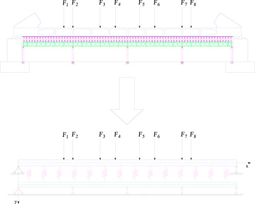
Figure 1. Schematic diagram of the synergistic stress model of double-layer elastic foundation beam.
2.3 Deflection differential equation for double-layer elastic foundation beams
The upper and lower beams can be considered as follows: the upper beam is subjected to a concentrated load and the reaction force is generated by the spring support between the upper and lower beams, the lower beam being subjected to the pressure generated by the spring support (Chen and Xue, 2024; Han et al., 2022).
The differential equation (Zhang et al., 2022) for the upper beam deflection curve can be expressed as follows:
Cause:
Available:
where
Cause:
Using the hyperbolic function, the general solution of the upper beam displacement equation can be expressed as follows:
Moreover, the general solution of the displacement equation of the lower beam can be expressed as follows:
2.4 Initial parametric solution of the deflection differential equation of double-layer elastic foundation beam
Regardless of the influence of shear on beam deflection, the angle (θ1), bending moment (M1), and shear force (Q1) of any section of the upper beam can be expressed as follows:
The lower beam arbitrary section angle (θ2), bending moment (M2), and shear force (Q2) can be expressed as follows:
Simplifying the solution of the above equations, we get:
Using the initial parameter method (Wang et al., 2024; He et al., 2024), the parameters of the upper beam at the initial section x = 0 can be defined as y10, θ10, M10, and Q10 and the parameters of the lower beam can be defined as y20, θ20, M20, and Q20, their values being determined by the boundary conditions.
The displacement, rotation angle, bending moment, and shear force of the upper beam can be expressed as follows:
Moreover, the displacement, rotation angle, bending moment, and shear force of the lower beam can be expressed as follows:
Thus far, the deflection, rotation angle, bending moment, and shear solution terms of the upper and lower beams obtained by the double-layer elastic foundation beam theory using the preliminary parameter method have been fully obtained.
2.5 Special solution terms for concentrated load action
The special solution terms for the double-layer beam must also be calculated based on the initial parameters. The lower beam is a four-span continuous beam system, the upper and lower beams being divided into L1–L4 at the lower-beam support. The equations for the upper and lower beams can be established in each section. In addition to considering the boundary conditions at the support of the upper and lower beams, it is necessary to consider the continuity conditions of the segmented upper and lower beams at the connection position, the boundary and continuity conditions together constituting the initial parameters of the equation solution. The mechanical calculation model for the upper beam, which bears only a single concentrated load action, is as shown in Figure 2.
For the calculated beam segment with a load action on the upper beam, as shown in Figure 2 (L3), when x > xi, the special solution term can be expressed as follows:
For the part of x < xi in the upper beam load action beam segment (L3) and the beam segment without load action (L1, L2, L4), the formula does not exist—that is, there are only general solution terms for the beam segment; the special solution terms are not generated by concentrated loads.
In the case of multiple concentrated loads acting simultaneously in the calculation of the double-layer beam, the complete solution for the displacement, rotation angle, bending moment, and shear force of the upper beam is equal to the general solution plus all the special solutions related to the concentrated load in this section (Wei et al., 2024c). The complete solution for the displacement, turning angle, bending moment, and shear force of the lower beam under a concentrated load is only a general solution, the expression still being the formula.
Based on the boundary conditions and continuous conditions of each beam segment, their corresponding parameters can be expressed using “preliminary parameters,” the deformation, rotation angle, bending moment, and shear force of the upper beam being expressed as follows: y1i, θ1i, M1i, and Q1i, and the deformation, corner, bending moment, and shear force of the lower beam being expressed as y2i, θ2i, M2i, and Q2i, where i = 1, 2, 3, 4. The boundary and continuity conditions can be expressed as follows:
(1) Boundary conditions: At
(2) Continuity conditions: The continuity condition occurs at the lower beam support position of the segmented connection—that is,
The displacement, rotation angle, bending moment, and shear force on both sides of the continuous point of the upper beam are continuous—that is, the beam displacement, bending moment, angle, and shear force of the segmented equations on both sides of the position at this point are equal. The initial parameters of each segmented equation can be obtained by solving the equations listed in the boundary and continuity conditions simultaneously, the complete analytical solution of the stress model of the double-layer beam structure being obtained using a complete expression.
3 Methods: model validation
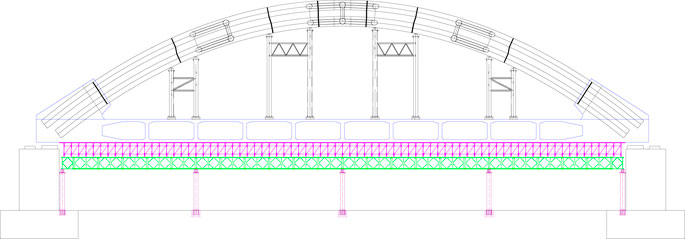
In this study, a 72-m under bearing concrete-filled steel tube arch bridge with a main span was used as an example to analyze the Bailey beam and column support. The beam and column brackets were as follows:15-mm bamboo rubber board → 10 × 10 cm square wood → I10 I-beam distribution beam → φ60 × 3.2 mm disc buckle bracket → I14 I-beam distribution beam → 321 standard Bailey beam longitudinal beam → double-split I45a I-beam crossbar → φ630 × 10 mm steel pipe column → reinforced concrete strip foundation. The coiled bracket above the Bailey beam was convenient to adjust the height of the formwork, the total height being 1.5 m, the vertical and horizontal spacing being 90 cm, and the maximum horizontal step distance being 100 cm. The lateral spacing of the Bailey beam was 90 cm, the longitudinal support spacing being 18 m, there being five rows of steel pipe supports. After the pouring of the tie beam was completed and the concrete strength met the necessary requirements, the arch ribs were installed, and four sets of steel tubular lattice columns were placed under the one-sided arch ribs. The arrangement of the brackets was as shown in Figure 3.
3.1 Model parameters
To verify the derivation formula, SAP2000 finite element software was used to establish the planar rod system synergistic force model of the tie beam and support, after which the synergistic forces of the two under the concentrated load of the tie beam were compared and analyzed. The model was constructed using beam elements, the top support of the tie beam pier being hinged, and the disc frame sandwich being simulated using only compressive elastic support. The transverse partition, arch rib concrete and arch rib support are only considered as weight in the calculation. The sandwich spring stiffness mainly considers the axial stiffness of the vertical bar of the disc buckle, which is equal to the product of the axial stiffness of the vertical bar divided by the vertical and horizontal distance of the vertical bar. The main model parameters are listed in Table 1.
The total weight of the arch ribs amounted to 20,446.4 kN, which includes concrete, steel pipes, and the load supported by the arch rib. Based on the positioning of the steel pipe columns on the tie beam, it is possible to calculate the load carried by each row of columns from the arch ribs.
3.2 Comparison of formula derivation and finite element calculation results
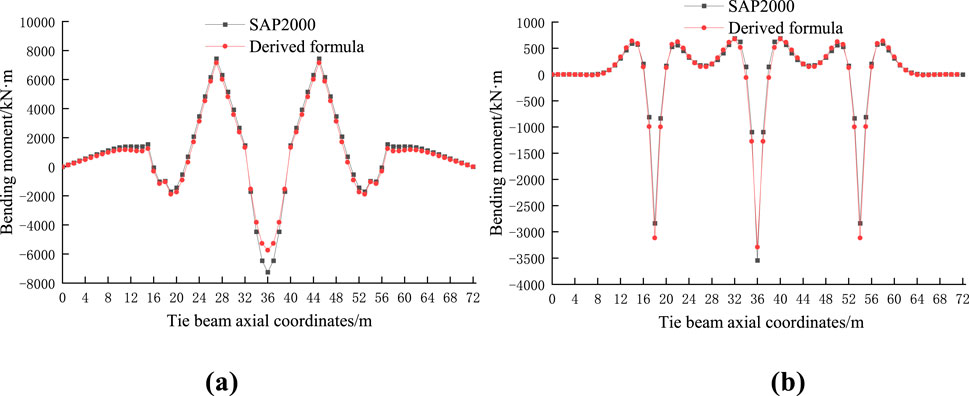
The parameters listed in Table 1 could be substituted into the derived calculation formula to determine the analytical solution of the deformation and internal force of the upper and lower beams, a comparative analysis with the calculation results of the finite element model being as shown in Figure 4.
As is evident from the figure, the maximum positive bending moment occurring at the second and third span concentrated load action points, and the maximum negative bending moment occurring at the support between the second and third spans. The consistency of the bending moment curve is high, although the difference is large at the extreme point, the negative bending moment of the upper beam having the largest difference at the middle fulcrum, albeit by less than 20%. The derivation formula and analysis results of the finite elements in this study are consistent. The maximum compressive stress and tensile stress of the upper beam are 0.42 and 0.34 MPa, respectively, and the bending moment of each row of the Bailey beams in the lower layer is 141.7 kNm, which is small compared with the normative limit.
For ease of analysis, the concept of the load-bearing ratio can be introduced, expressed as follows:
where δ denotes the bear-to-load ratio,
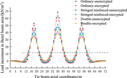
The bearing ratio of the Bailey beam support under a concentrated load can be calculated to be 90.9%, the Bailey beam baring most of the later loads. Compared with the traditional equalization method, the load increment at the support of the Bailey beam increases. Under an actual concentrated load, the traditional equalization method can be used to calculate the load increment of the Bailey beam, which is unsafe at the support of the steel pipe column, the load increment at this position being large and in need of being strengthened.
4 Results: Parameter sensitivity analysis
4.1 Concrete strength grade
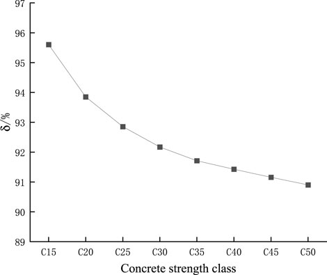
The elastic modulus of the tie concrete primarily affects the stiffness of the tie beam, and different concrete strength grades indicate different elastic moduli. Figures 5, 6 show the calculation results of the bending moment and bearing ratio of the tie beam and Bailey beam under loading.
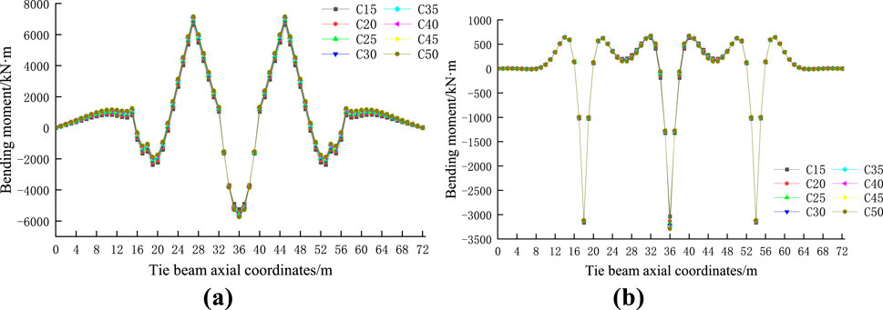
Figure 5. Comparison of bending moments of different concrete strength grades of (A) Tied beam (B) Bailey beam.
From the above analysis, it is evident that the concrete strength grade has little effect on the bending moment of the tie beam and Bailey beam but has a considerable influence on the support bearing ratio. With an increase in the concrete strength grade, the elastic modulus, and maximum bending moment of the tie beam and Bailey beam gradually increase, which means that with an increase in stiffness, the load shared by the concrete beam gradually increases, and the bearing ratio gradually decreases.
4.2 Analysis of the height influence of the tie beam section
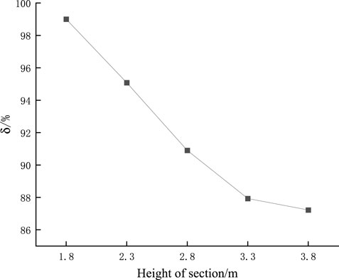
Figures 7, 8 show the results of the bending moment and bearing ratio of the tie beam and Bailey beam under concentrated loading.
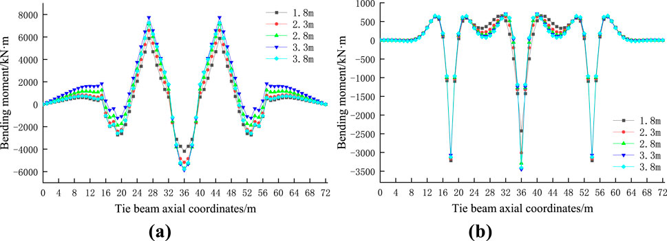
Figure 7. Comparison of bending moment of different tether section heights of (A) Tied beam (B) Bailey beam.
The bearing ratio decreases with an increase in the cross-sectional height, the reduction in amplitude is large, the bearing ratio is 99.2% when the cross-sectional height is 1.8m, and the tie beam bares little of the load. From the above analysis, it is evident that for the Bailey-beam-column bracket, changing the section height of the tie beam has a little effect on the bending moment of the two beams, and a greater impact on the bearing ratio of the bracket.
4.3 Impact analysis of sandwich stiffness
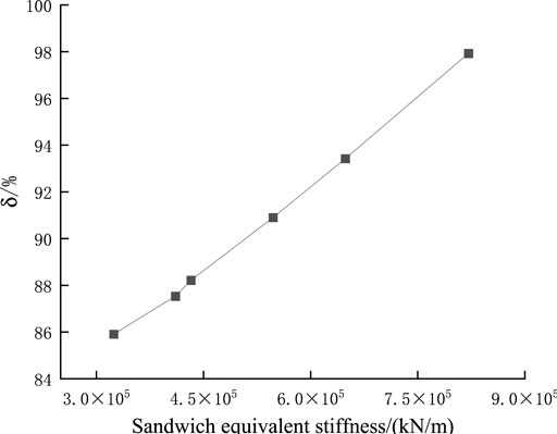
The calculated beam and column bracket sandwich comprised a bamboo rubber board + square wood + distribution beam + disc frame + distribution beam, the height of the disc buckle frame being 1.5 m, the pole specification being a φ60 × 3.2 mm heavy-duty disc buckle frame, and the horizontal spacing of the pole being 0.9 × 0.9 m. The transverse spacing of the heavy-duty and standard disc-fastener frames was 0.9 m, the longitudinal spacing being 0.6, 0.9, and 1.2 m, respectively, the values of the sandwich stiffness sensitivity analysis being as listed in Table 2.
Figures 9–12 show the results of the bending moment, load increment, and bearing ratio of the tie beam and Bailey beam under concentrated loading.

Figure 9. Comparison of the tie-beam bending moment under different sandwich stiffness conditions of (A) Standard disc collar (B) Heavy-duty disc collar.

Figure 10. Comparison of the Bailey-beam bending moment under different interlayer stiffness conditions of (A) Standard disc collar (B) Heavy-duty disc collar.
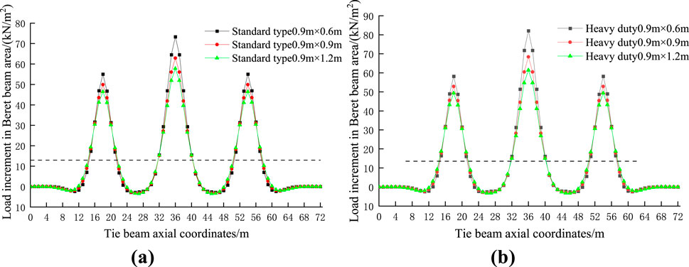
Figure 11. Comparison of the Bailey beam incremental load of (A) Standard disc collar (B) Heavy-duty disc collar.
Under the action of a concentrated load, the bearing ratio of the bracket increases with the increase of the interlayer stiffness, and the increase is large, the bearing ratio reaching 97.9% when the heavy-duty disc frame is adopted and the arrangement spacing being 0.6 × 0.9 m. Changing the interlayer stiffness of the double-layer beam has little influence on the bending moment, and a great impact on the bearing ratio of the bracket.
4.4 Analysis of the influence of bailey beam arrangement
The lateral arrangement spacing of the Bailey beams was calculated to be 90 cm with a total of 25 rows. In practice, to ensure a uniform bracket force, it is often encrypted under the box girder web, the transverse after encryption having 31 rows. To enhance its span ability, the upper and lower reinforced Bailey beam and the double-layer Bailey beam are also commonly used as the main longitudinal beam of the bracket. To explore the influence of the type and number of transverse rows on the synergistic force, 25 and 31 rows of ordinary, upper, and lower chord-reinforced, and double Bailey beams were considered and analyzed, the sensitivity analysis results for the Bailey beam arrangement being as listed in Table 3.
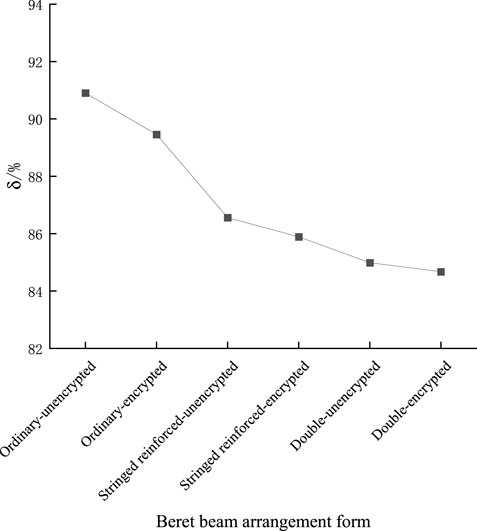
Figures 13–15 show the results of the bending moment, load increment, and bearing ratio of the moored and Bailey beams under concentrated loading.

Figure 13. Comparison of the bending moments of different Bailey beam arrangements of (A) Tied beam (B) Bailey beam.
Different Bailey beam types and arrangements have little influence on the bending moment of the tie beam, greater impact on the bending moment of the Bailey beam, and little influence on the bearing ratio. The load ratio decreases with an increase in the moment of inertia of the Bailey beam, the reduction range being small. However, when a double-layer Bailey beam is used, and the bearing ratio is only 84.7% when encrypted.
5 Conclusion
To study the synergistic stress phenomenon between beam and column brackets and tie beams during the construction of a concrete-filled steel tube tie-arch bridge, we optimized the design theory of temporary supports, established the double-layer beam theory based on the Winkler elastic foundation beam theory, constructed a synergistic force model of the tie beam-beam-column support, and derived the displacement, rotation angle, bending moment, and shear force equations of the tie beam under concentrated loading. The conclusions drawn are as follows.
(1) Combined with the synergistic force of the tie-beam–beam-column bracket, the deflection curve differential equation of the deformation of the moored beam and Bailey beam could be derived and solved; the calculation method of the deformation and internal force of the tie beam and Bailey beam was obtained, and the distribution law of the load increment of the Bailey beam determined.
(2) A 72-m underbearing concrete-filled steel tube arch bridge was used as the research object to calculate the collaborative force, after which the displacement, bending moment, and load increment of the tie beam and Bailey beam were compared and analyzed using the finite element method. The results showed that under the action of a concentrated load, the regional load increment of the Bailey beam at the support of the steel pipe column was large, far larger than the load increment calculated based on traditional average division methods, making the beam and column support Bailey beam calculated using traditional average division methods unsafe—that is, the structure should be strengthened accordingly.
(3) The strength grade of the tie beam concrete had little effect on the displacement, bending moment, and bearing ratio of the tie beam and Bailey beam. However, the section height of the tie beam had a considerable influence on the displacement of the tie beam and Bailey beam, little effect on the bending moment of the two beams, and a major influence on the bearing ratio. The arrangement of the sandwich disc buckle frame had a considerable influence on the displacement of the tie and Bailey beams, little influence on the calculation results of their bending moments, and a substantial influence on the bearing ratio of the bracket. The arrangement of the Bailey beam had a considerable influence on the displacement of the tie and Bailey beams, little influence on the calculation results of the bending moment of the two beams, and little influence on the bearing ratio of the bracket.
(4) Under a concentrated load during the later stage, the stress of the concrete tie beam was low, which could satisfy design requirements. Moreover, the bearing ratio of the brackets did not change much, with the beam and column brackets bearing most of the later loads.
Data availability statement
The original contributions presented in the study are included in the article/supplementary material, further inquiries can be directed to the corresponding author.
Author contributions
JT: Conceptualization, Writing–original draft. HW: Investigation, Writing–original draft. DX: Methodology, Supervision, Investigation, Writing–review and editing. CT: Writing–review and editing.
Funding
The author(s) declare that no financial support was received for the research, authorship, and/or publication of this article.
Conflict of interest
Authors JT and HW were employed by Lunan High Speed Railway Co. Author DX was employed by Jinan Zhiye Electronic Co., LTD. Author CT was employed by China Construction Infrastructure Co. Ltd.
Generative AI statement
The author(s) declare that no Generative AI was used in the creation of this manuscript.
Publisher’s note
All claims expressed in this article are solely those of the authors and do not necessarily represent those of their affiliated organizations, or those of the publisher, the editors and the reviewers. Any product that may be evaluated in this article, or claim that may be made by its manufacturer, is not guaranteed or endorsed by the publisher.
References
Chen, H., Liao, F., Yang, Y., and Ren, Y. (2023). Behavior of ultra-high-performance concrete (UHPC) encased concrete-filled steel tubular (CFST) stub columns under axial compression. J. Constr. Steel Res. 202, 107795. doi:10.1016/j.jcsr.2023.107795
Chen, J., and Xue, J. (2024). Simplified finite-element analysis method for local and global prediction on axial compression behavior of square spiral-confined reinforced concrete-filled steel tubular columns. Structures 66, 106881. doi:10.1016/j.istruc.2024.106881
Ding, L. Y., Zhong, B. T., Wu, S., and Luo, H. B. (2016). Construction risk knowledge management in BIM using ontology and semantic web technology. Saf. Sci. 87, 202–213. doi:10.1016/j.ssci.2016.04.008
Han, X., Han, B., Xie, H., Yan, W., Yu, J., He, Y., et al. (2022). Seismic stability analysis of the large-span concrete-filled steel tube arch bridge considering the long-term effects. Eng. Struct. 268, 114744. doi:10.1016/j.engstruct.2022.114744
Han, X., Wei, C., Hu, Q., Liu, C., and Wang, Y. (2024). In-plane nonlinear buckling analysis and design method of concrete-filled steel tubular catenary arches. J. Constr. Steel Res. 214, 108485. doi:10.1016/j.jcsr.2024.108485
He, F., Li, C., Shen, W., Chen, B., and Briseghella, B. (2024). Compressive behavior of steel tube reinforced concrete column under eccentric loads. J. Constr. Steel Res. 219, 108787. doi:10.1016/j.jcsr.2024.108787
He, S. (2019). Stress characteristics and experimental study of support system of giant beam in layered pouring construction. Lanzhou: Jiaotong. Univ., 1–2.
Huang, W. F., Shao, Y. B., Hassanein, M. F., Hadzima-Nyarko, M., Radu, D., and Cashell, K. (2024). Experimental and numerical investigation of square concrete-filled double-skin steel stiffened tubular stub columns with CHS inner tubes under axial compression. Thin Wall Str. 199, 111792. doi:10.1016/j.tws.2024.111792
Junmei, H. (2014). Pushing construction technology for the 156 m simply supported steel truss girder of New Yellow River Bridge. J. Railw. Constr. Technol. (5), 64–67.
Li, W. (2022). Construction of wanxian Yangtze River Highway bridge. Department of Science and Technology Education, 629–633.
Lin, J. R., Zhang, J. P., Zhang, X. Y., and Hu, Z. Z. (2019). Automating closed-loop structural safety management for bridge construction through multisource data integration. Adv. Eng. Softw. 128, 152–168. doi:10.1016/j.advengsoft.2018.11.013
Liu, W., Dai, G., and He, X. (2013). Sensitive factors research for track–bridge interaction of longspan X-style steel-box arch bridge on highspeed railway. J. Cent. South Univ. 20 (11), 3314–3323. doi:10.1007/s11771-013-1855-6
Lu, B., Fang, Y., Elchalakani, M., Wang, Y., and Yang, H. (2024). Behaviour of concrete-filled double-skin thin-walled corrugated steel tubes under axial compression. Thin Wall Struct. 205, 112388. doi:10.1016/j.tws.2024.112388
Luo, X., Yu, X., Wei, J., Yang, Y., Qiao, H., et al. (2024). Structural performance of ultra-high strength concrete filled high strength steel tube stub columns under eccentric loading. J. Build. Eng. 97, 110752. doi:10.1016/j.jobe.2024.110752
Nugroho, D. T., Nur, M., and Purba, H. H. (2020). Bridge project development risk management: a literature review. EPRA Int. J. Multidiscip. Res. 6 (1), 1–7. doi:10.36713/epra3952
Qi, Q., Jia, P., Wan, C., and Haipeng, W. (2024). Behavior of concrete-filled double steel tube stub columns under partial compression. J. Constr. Steel Res. 214, 108451. doi:10.1016/j.jcsr.2024.108451
Tang, J. (2018). Experimental study and finite element analysis of the early disassembly system of template support. Tech: Kunming. Univ. Scien., 1–2.
Wang, A., Zhang, T., and Yu, D. (2012). Analysis research on the steel rein forced concrete beam and the scaffolding support system. J. Qingdao. Univ. Tech. 33, 111–116.
Wang, J., Han, J., Zhu, C., Lu, W., Zhang, Y., He, X., et al. (2024). Structural optimization and engineering application of concrete-filled steel tubular composite supports. Eng. Fail Anal. 159, 108082. doi:10.1016/j.engfailanal.2024.108082
Wang, Q. (2022). Research on tie beam and support cooperative stress of steel tube-confined concrete tied arch bridge based on elastic foundation beam theory. Yantai: Univ., 1–2.
Wei, C., Liu, C., Hu, Q., Wang, D., and Wang, Y. (2024a). In-plane behaviors of FRP confined concrete-filled steel tubular arches under mid-span concentrated loads. Structures 68, 107151. doi:10.1016/j.istruc.2024.107151
Wei, J. G., Han, J. P., Luo, X., and Yang, Y. (2024c). Eccentric load capacity of ultra-high strength concrete-filled steel tubular lattice short columns. Structures 69, 107385. doi:10.1016/j.istruc.2024.107385
Wei, J. G., Han, J. P., Luo, X., Yang, Y., and Wang, W. R. (2024b). Axial compression performance of ultra-high-strength concrete filled steel tubular lattice short columns. J. Constr. Steel Res. 216, 108571. doi:10.1016/j.jcsr.2024.108571
Xia, A., Zheng, T., Shao, J., and Tan, T. (2024). Impact of steel tube wall thickness on axial compression behavior of reinforced and recycled aggregate concrete-filled square steel tube short columns. Structures 69, 107382. doi:10.1016/j.istruc.2024.107382
Xie, B. (2022). Design and construction technology of Wanxian Yangtze River Bridge mega-span (420m) concrete arch bridge. First. Natl. Highw. Sci. Technol. Innovation. high-level. Forum, 619–623.
Xie, K., Huang, K., Huang, L., and Zhu, T. (2023). Experimental study of bond behavior between concrete-filled steel tube and UHPC-encased. Constr. Build. Mater 409, 134016. doi:10.1016/j.conbuildmat.2023.134016
Yan, X., Liu, Y., Liu, J., Lyu, Y., Wang, X., and Jia, J. (2024). Experimental and numerical investigation on vertical temperature gradient of concrete-filled steel tubular arch under sunlight. Structures 70, 107550. doi:10.1016/j.istruc.2024.107550
Keywords: double-layer elastic foundation beam, concrete-filled steel tube tied-arch, bailey beam, collaborative stress, bearing ratio
Citation: Tong J, Wang H, Xu D and Tian C (2025) Collaborative stress of concrete-filled steel tube tied-arch beam-column support based on the double-layer elastic foundation beam theory. Front. Built Environ. 10:1517741. doi: 10.3389/fbuil.2024.1517741
Received: 27 October 2024; Accepted: 26 November 2024;
Published: 07 January 2025.
Edited by:
Ruizhao Zhu, Southeast University, ChinaReviewed by:
Chaoliang Fu, RWTH Aachen University, GermanyQilin Yang, Harbin Institute of Technology, China
Boshan Zhang, Tongji University, China
Copyright © 2025 Tong, Wang, Xu and Tian. This is an open-access article distributed under the terms of the Creative Commons Attribution License (CC BY). The use, distribution or reproduction in other forums is permitted, provided the original author(s) and the copyright owner(s) are credited and that the original publication in this journal is cited, in accordance with accepted academic practice. No use, distribution or reproduction is permitted which does not comply with these terms.
*Correspondence: Changjin Tian, MTc4NjI5OTA3MjlAMTYzLmNvbQ==
 Jiazhu Tong1
