- 1Automatic Control Group–ACG, Department of Automatic Control and Systems Engineering, Faculty of Engineering of Bilbao, Institute of Research and Development of Processes–IIDP, University of the Basque Country–UPV/EHU, Bilbao, Spain
- 2Industrial and Civil Engineering School, Universidad de Las Palmas de Gran Canaria, Las Palmas de Gran Canaria, Spain
Floating offshore wind turbines (FOWTs) are highly susceptible to vibrations caused by wind and sea wave oscillations, necessitating effective vibration reduction strategies to ensure stability and optimal performance. This study investigates the effectiveness of a barge-type FOWT integrated with oscillating water columns (OWCs) in reducing oscillations, particularly in rotational modes. A hybrid FOWT-OWCs system was designed, and its vibration mitigation capabilities were assessed through both numerical simulations and experimental tests. The numerical approach focused on controlling airflow in the OWCs, while the experimental tests validated these results under similar conditions. A strong agreement between the simulations and experiments was observed, particularly in reducing platform pitch oscillations, even under irregular wave conditions. The open OWC-based platform outperformed the closed design, reducing pitch angle oscillations from 17.51° to 14.38° for waves with a 10-s dominant frequency. Benchmark tests confirmed this trend, with the open moonpool-based platform achieving a reduction from 18.41° to 12.23°. These findings demonstrate the potential of OWCs to improve the stability and performance of FOWTs, with experimental validation providing confidence in the numerical predictions.
1 Introduction
The world’s wind energy sector is expanding, and wind energy is gradually replacing fossil fuels. Due to the impacts of climate change and global warming, renewable energy resources such as wind and wave power are gaining in popularity. In order to meet these challenges, the construction of wind and wave energy supply infrastructure is essential. The possibility of obtaining clean, renewable offshore wind and wave energy has been enhanced by the development of floating offshore wind turbines (FOWTs) (Maxwell et al., 2022).
There is greater potential in offshore than onshore energy sources due to the former’s larger capacity factors, more accessible area, and less visible effects (Jahani et al., 2022). One promising approach is the integration of Oscillating Water Columns (OWCs), which are a specific type of Wave Energy Converter (WEC). While WECs encompass a variety of technologies designed to capture and convert wave energy into useable power, OWCs utilize the principle of oscillating water to generate energy. The integrated system can create a hybrid structure for harnessing of both wind and wave energy (Kluger et al., 2017). Integrated FOWT-OWC systems have the potential to significantly reduce costs by leveraging operation while sharing maintenance costs and a common grid infrastructure. Integrated systems can also enhance power output and efficiency (Fu et al., 2019). However, one of the difficulties that needs to be dealt with is the stability of FOWTs in order to reduce unwanted platform vibrations and capture as much energy as is feasible. These undesirable movements diminish aerodynamic efficiency, limit tower fatigue life, and raise loads on blades, rotor shafts, yaw bearings and tower bases (Haji et al., 2018). It is therefore vital to keep the system movements inside a reasonable limit (Lackner, 2013).
Pérez-Collazo et al. (2015) suggested an approach that classified systems as either co-located or hybrid according to the degree of integration between wind turbines and wave energy converters (WECs). The co-located system is the most basic option for power generation, as it includes wind and wave farms individually while sharing advantages of maritime space and electricity infrastructures (Xilin et al., 2004). A hybrid system, which is the case study in this article, merges the foundations of the wind and wave energy capturing structures. This can be achieved by either designing new structures or modifying existing ones (Dong et al., 2022).
Several researchers have proposed modified floating structures for so-called hybrid systems. Moghimi et al. (2020) investigated the performance of four floats attached to a wind turbine for energy improvement. Zhu et al. (2024) introduced a novel hybrid energy system that utilizes an oscillating hydrofoil attached to the underwater tower of offshore wind turbines to capture tidal current energy, improving overall efficiency and reducing drag on the turbine structure. Ren et al. (2020) compared numerical and experimental results for the combination of a tension leg platform and heave-type WEC. Sarmiento et al. (2019) integrated three OWCs in a semisubmersible multi-use platform in order to describe the platform’s overall response and the performance of the OWCs. Hu et al. (2020) developed an optimization method concept of the integration of multiple heaving WECs in a floating wind platform in order to study the platform motion and harnessed wave power. Ghafari et al. (2022) developed a numerical method to study surge, heave and pitch movements and the absorbed power of a Wavestar WEC with multi-point absorber around a semisubmersible platform. Haji et al. (2018) reported that the integration of three WECs and a FOWT could lead to increased energy capture and platform motion reduction. Other alternatives include the use of a gyro-stabilizer (Palraj and Rajamanickam, 2020) or dampers (Yang et al., 2019; Wei and Zhao, 2020) in the nacelle or the platform to reduce the system’s vibration. Modifying the platform is also one approach that can be used to describe the motions of the system in various sea states, as has been done with catamaran-type platform models (Cutler et al., 2022). Another method to reduce vibrations of an offshore turbine can be the use of tuned mass dampers (Sarkar and Fitzgerald, 2022; Jahangiri et al., 2021; Kampitsis et al., 2022). Nazokkar and Dezvareh (2022) examined the use of tune liquid mass dampers to resduce the platform’s pitch displacement in semisubmersible FOWTs. Chen et al. (2024) demonstrated that optimized wave energy converter (WEC) power take-off (PTO) control can enhance wave power production, reduce platform pitch oscillations, and mitigate tower base loads in a floating wind-wave combined system. Sebastian et al. (2024) investigateed the dynamic behavior of hybrid wind-wave energy systems combining OWCs with a DeepCwind semi-submersible platform, demonstrating that OWCs reduce platform motion and that a single OWC offers the highest energy capture efficiency.
However, very few studies have considered the use of barge-type FOWTs as part of a hybrid OWC-FOWT system. Jonkman (2007) integrated a closed moonpool at the center of a barge platform and argued that an OWC could be applied in the tower for energy integration. In Ahmad et al. (2023a); Ahmad et al. (2023b), I. Ahmad et al. proposed a machine leaning approach to identify and control a FOWT-OWCs system. M’zoughi et al. (2021) simplified a nonlinear hybrid OWC-FOWT system to reduce platform pitch and tower top fore-aft displacement. In Aboutalebi et al. (2021a); Aboutalebi et al. (2024), Aboutalebi et al. (2021b); Aboutalebi et al. (2022) numerically described the system motions in barge-type and semisubmersible FOWTs, and in proposed a switching controller to reduce the system’s oscillations in the absence and presence of wind and in different sea states.
This article introduces a numerical method for analyzing the rotational performance FOWT-OWC hybrid platforms using response amplitude operators (RAOs). Besides, an experimental study is conducted on a prototype to validate the numerical findings. This comparison involves open and closed moonpools at the hybrid platform under specific sea conditions, aiming to assess the degree of oscillation reduction in the platform’s pitch angle–the primary focus of this research. Remarkably, the hybrid system does not only contributes to minimizing fatigue but also exhibits the potential to increase the efficiency of ocean energy harvesting through pitch reduction, thereby extending the platform’s lifespan and enhancing energy production. The novelty of this research lies in the comprehensive comparative analysis of the RAOs for original FOWTs-OWCs versus scaled hybrid FOWTs with moonpools. This study provides valuable insights into the significant impact of integrating OWCs on vibration reduction, showcasing the effectiveness of this hybrid configuration in mitigating oscillations in various modes. By combining both numerical and experimental methodologies, our work offers a robust framework for understanding the dynamic behavior of floating offshore structures and paves the way for future design improvements in the field.
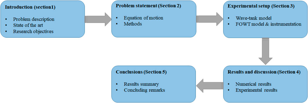
The rest of the article is organized as follows: Section 2 describes the equations of motion for the hybrid system and the method used to analyze the system performance using RAOs. The experimental requirements for the FOWT model and instrumentation are described in Section 3. Section 4 discusses both the numerical and the experimental results obtained from the numerical simulations and the experimental tests, respectively. Finally, Section 5 includes the conclusions of the article. As shown in Figure 1, the structure of the paper is outlined in a flowchart, highlighting the organization of the sections.
2 Problem statement
It is essential to address the issue of FOWT structure oscillations as they reduce aerodynamic performance and tower fatigue life by adding unwanted loads on the blades, rotor shaft, yaw bearing and tower. A promising approach to reduce the structural oscillations of the system as well as to harvest wave energy with a slave control is to employ OWCs or moonpools as OWC air chambers. The OWCs are strategically controlled to reduce platform oscillations, independent of the amount of harvested wave energy, utilizing the air valves within each chamber for this purpose. Essentially, each OWC comprises an air chamber with a sea opening below the waterline, connected to a turbine generator based on a power take-off (PTO) system. When waves impact the chamber, water enters and compresses the air inside, activating the turbine to generate torque for the generator. As the wave water recedes, the air is released in the opposite direction, but the turbine’s self-rectifying design keeps it rotating in the same direction. As the primary objective, the deployment of OWCs centers around mitigating oscillations in the hybrid system. This is achieved through the efficient control of air compression and decompression within the air chambers using their valves (Garrido et al., 2012; Amundarain et al., 2010). As a secondary objective, these OWCs also serve the purpose of power generation. This section describes the numerical and experimental approaches to solving the problem as well as the nonlinear equation of the hybrid system.
2.1 Equation of motion
Irregular or random waves representing various stochastic sea states are characterized as the sum or combination of multiple wave elements defined from a suitable wave spectrum. This article includes the Joint North Sea Wave Project (JONSWAP) spectrum for the irregular wave in order to specify the wave spectrum. The one-sided JONSWAP spectrum is described in the IEC 61400-3 design standard as follows (Jonkman, 2007):
where
and the peak shape parameter can be expressed as Equation 2:
After defining the equation of the waves, the general equation of motion of the FOWT in frequency-domain can be described as:
where
Note that the states correspond to the rigid-body motions of the structure. The inertia elements of the FOWT are specified in Equation 5 as following:
the term
The stiffness element
where
The damping elements can be obtained by Equation 7 as follows:
here
where p is the pressure drop inside the turbine and S is the internal free surface area of water. Assuming that the air is an ideal gas and the air compression/decompression is an isentropic process, the time-dependent air density may be described as:
the terms
The linearized mass flow inside the turbine is described in Equation 11 as (M’zoughi et al., 2018):
where V and
Considering non-dimensional turbo-machinery nomenclature, a Wells turbine with diameter D and rotational velocity N is examined through a linear connection between the pressure and flow coefficients as described in Equation 12:
here the pressure and flow coefficients can be defined in Equations 13, 14 as:
Assuming the pressure drop is proportional to the flow rate, non-dimensionalization is applied. Thus, the linear relation can be obtained as:
where the pressure and flow coefficients are described as follows:
the term g is the gravity acceleration and H is the wave height. Incorporating Equations 15–17 into Equation 11, the mass flow inside the turbine is given by:
Combining Equations 11, 18, the pressure complex amplitude can be described as:
where
Considering Equations 8, 19, the PTO force can be described in Equation 22 as:
where
Hence, the frequency domain equation of motion of the system defined in Equation 3 is given by Equation 25 as follows:
where
2.2 Methods
In order to evaluate the performance of the proposed platform, two approaches were considered using numerical and experimental methods.
The numerical approach involves use of the mean values of RAO indicators. For this, MultiSurf, WAMIT, FAST and MATLAB software were employed.
The MultiSurf tool was used to represent various offshore body geometries. As can be seen in Figure 2, two platforms were compared, a closed and an open OWC-based platform. The platforms are equipped with four OWCs. The platform design is detailed in Table 1. Note that the water displacement for both platforms is 6,000
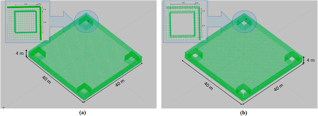
Figure 2. Platforms structure with OWCs topology for (A) Closed OWCs-based platform. (B) Open OWCs-based platform.
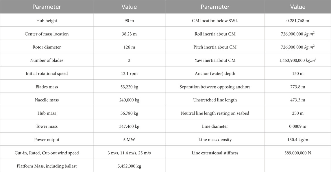
The platform panel geometry defined in MultiSurf can be integrated in WAMIT (Lee and Newman, 2013) in order to calculate added mass, damping, hydrostatic and hydrodynamic force matrices. Then, these matrices can be included in FAST to model the system. The characteristics of the FOWT are detailed in Table 2.
In order to analyze the behavior of the systems, RAOs were utilized to have an input-output for system responses against various wave inputs. The frequency-response function (FRF) or RAOs can be calculated through Equation 26 as (Pintelon and Schoukens, 2012):
where
where
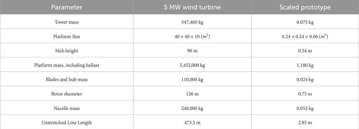
In order to conduct the experimental test, a small 3D printed prototype of the floating wind turbine was obtained. The characteristics of the FOWT prototype are detailed in Table 3.
The experimental tests were carried out on two platforms: a closed and an open moonpool-based platform. Both platforms were subjected to an irregular wave to assess the extent of oscillations in their rotational modes. The moonpools integrated into the platforms served as the air chambers for the OWCs, allowing the regulation of airflow by opening or closing the moonpools, as previously demonstrated in our earlier studies (Aboutalebi et al., 2021a; Aboutalebi et al., 2021b, Aboutalebi et al., 2022).
In this study, both numerical simulations and experimental testing have been utilized to analyze the dynamic behavior of FOWTs with and without OWCs. The numerical simulations provided a comprehensive framework to predict the RAOs under varying wave conditions, allowing us to understand the system’s performance across different configurations. To validate the numerical results, experimental tests have been conducted using a scaled model of the FOWT in a wave basin, applying Froude similarity to ensure dynamic similarity with full-scale conditions. The experimental data confirmed the numerical findings, demonstrating the effectiveness of OWCs in reducing platform vibrations, particularly in pitch and roll motions. This dual approach strengthens the reliability of the results and enhances the overall understanding of the dynamic interactions between wave forces and floating structures.
3 Experimental setup
3.1 Wave-tank model
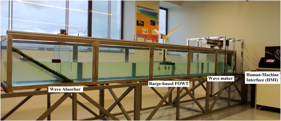
All the experimental tests presented in this article were conducted in the Automatic Control Group (ACG) laboratory in the University of the Basque Country (UPV/EHU). The wave tank, available in the laboratory, is made of stainless steel due to its continuous contact with water. The sides and base are made of glass, except for two plates at both ends of the base, which are made of methacrylate to facilitate the fixing of the structures. The wave tank is 4.750 m*0.550 m*0.650 m (L*W*H). Figure 3 shows the configuration of the floating platform, mooring lines, and water level sensors, along with the dimensions of the wave tank.
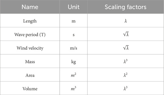
To scale the floating platform, Froude scaling factors have been employed as outlined in Table 4. The properties and components of the scale model were designed using SolidWorks CAD software and subsequently assembled. ABS plastic was chosen for its durability, low density, resilience, and water resistance to 3D print the platform components. This material choice enabled us to verify the model’s buoyancy.
When validating the design of offshore wind turbines, these scaling factors ensure that the physical tests conducted on scaled models or in simulation environments accurately reflect the real conditions experienced by full-scale turbines. This includes considerations for structural loads, aerodynamic forces, hydrodynamic forces, and operational performance under different environmental conditions.
If a wind turbine model is built at a 1:166.6 scale, the geometric scaling factor
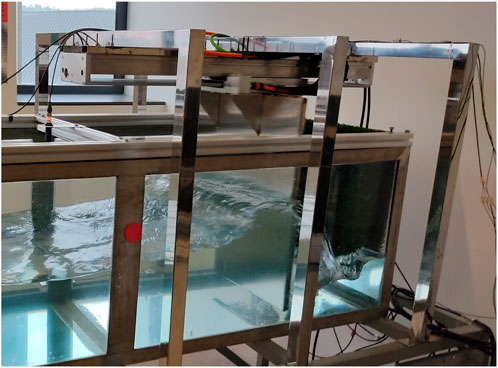
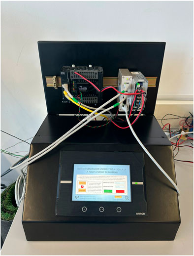
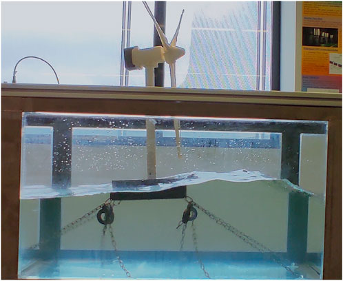
As can be seen in Figure 4, the wave tank consists of a wave absorber, a barge-based FOWT and a wave generator. A human-machine interface (HMI) was used to control the movements of the paddle used for forming waves inside the wave tank (see Figure 5). For the interface, Sysmac Studio software compatible with OMRON equipment has a simple and intuitive interface that is divided into two general sections, one associated with the configuration of the controllers (PLC) and the other associated with the HMI (screens, control commands, etc.), as shown in Figure 6.
3.2 FOWT model and instrumentation
A small scale prototype of the NREL 5 MW FOWT with modified platform was modeled as shown in Figure 7. The FOWT includes eight catenary mooring lines, nacelle, blade, rotor, tower and platform.
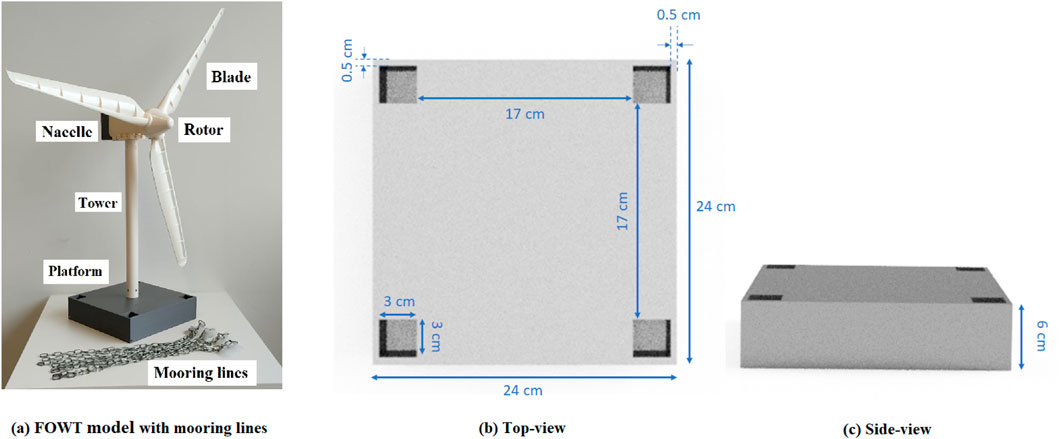
Figure 7. Scaled model design (A) FOWT model with mooring lines (B) Platform’s top-view (C) Platform’s side view.
The mooring lines are made of stainless steel chain, attached to the corners of the platform (two mooring lines at each corner) to keep the platform from drifting. The platform is 24 cm × 24 cm × 6 cm. Four moonpools were integrated at the corners with a distance of 0.5 cm from the sides. Each equipped moonpool has a size of 3 cm × 3 cm × 6 cm.
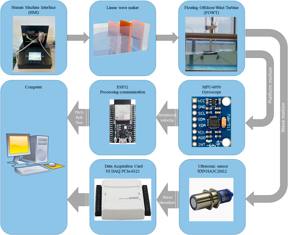
To measure the rotational movements of the platform, an electronic board was placed on the top of the nacelle. The board consists of an ESP32 module, an MPU6050 module and a 5 v power source. In order to obtain rotational moments, the ESP32 was interfaced with the MPU6050. The MPU6050 is an accelerometer and gyroscope module that measures rotational angles including pitch, roll and yaw. The ESP32 was used to transfer the obtained rotational movements data via WiFi to the CPU in the computer. Finally, Matlab was the interface used to monitor the rotational movements of the platform. A schematic representation of the measurement instrumentation setup used in the experimental tests is provided in Figure 8. This figure illustrates the sensor for thre measurement of pitch, roll and yaw displacements, data acquisition systems, and other relevant devices on the platform.
4 Results and discussion
This section is divided into the numerical results obtained from the theoretical study and the experimental results obtained from the benchmark tests in the ACG laboratory.
4.1 Numerical results
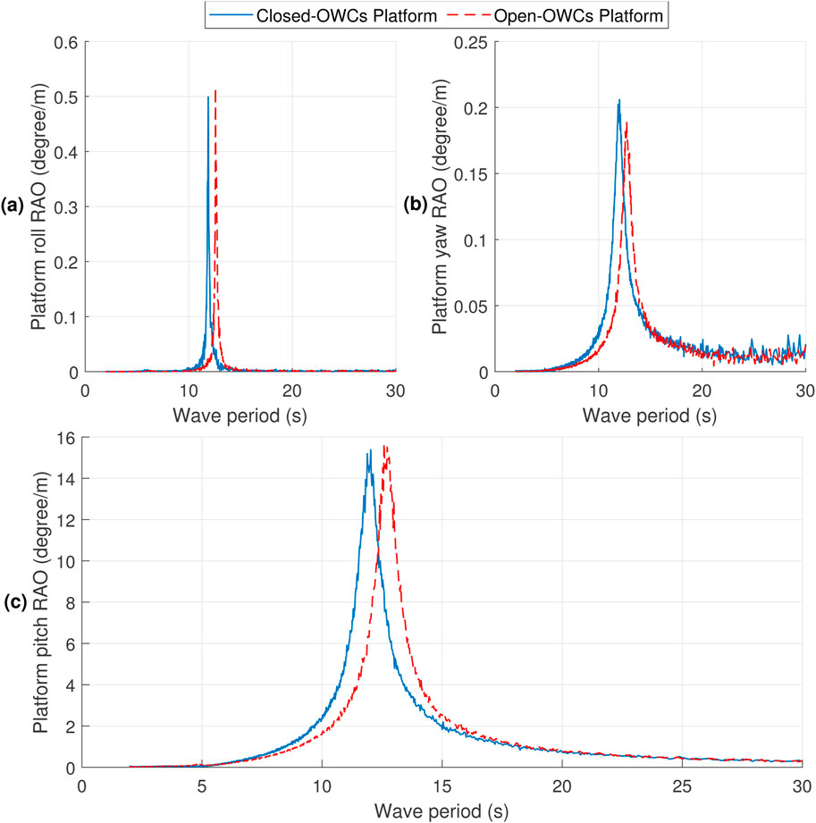
OWCs primarily dampen rotational modes (pitch, roll and yaw) rather than translational modes (surge, sway, and heave) in FOWTs. Rotational motions are more sensitive to wave forces, making OWCs more effective in reducing these oscillations. In contrast, translational modes are influenced by linear hydrodynamic forces, where the effect of OWCs is smaller. This paper focuses on the rotational modes, where OWCs have the most significant impact on vibration reduction. After obtaining the rotational modes RAOs using the equations detailed in Section 2.2, three informative Figures 9A–C can be plotted, depicting the platform’s roll, yaw, and pitch RAOs, respectively. Note that the similations have been conducted in absence of wind so that the blades angle kept and locked at 0°. The RAOs are illustrated with blue and red curves corresponding to the closed-OWC platform and open-OWC platform, respectively. As may be seen in Figures 9A, B, the RAO values for the roll and yaw modes appear to be relatively small, suggesting that the oscillations induced by the imposed wave along the surge mode are minor.
In Figure 9C, the platform pitch RAO takes center stage as the most significant among the RAOs due to its considerable value. As depicted, the platform pitch RAO exhibits a progressive increase for both closed and open OWC-based platforms until they reach their respective resonance periods. Subsequently, the platform pitch RAO descends, eventually approaching around zero for long-term wave periods. In simpler terms, the platforms’ oscillations intensify as they approach their natural frequencies, followed by a gradual decrease to slightly above zero for longer wave periods. An intriguing observation is that the platforms’ pitch curves intersect precisely at the wave period of 12.32 s, representing a critical point of interaction. Analyzing the behavior for wave periods lower than 12.32 s, it becomes evident that the open OWC-based platform exhibits lower oscillations compared to the closed OWC-based platform. However, a different pattern emerges for wave periods higher than 12.32 s, where the oscillations in the closed OWC-based platform become lower in comparison.
Considering the above results, an irregular wave with a significant period of 10s and wave amplitude of 5m, based on the JONSWAP spectrum, was imposed on the 5 MW barge-based floating offshore wind turbine (FOWT) system, as illustrated in Figure 10A.
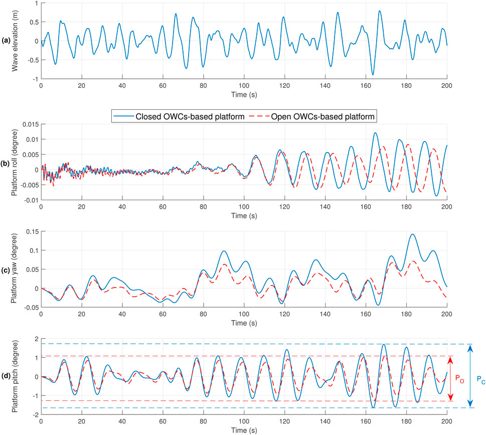
Figure 10. Numerical results for (A) Wave input. (B) Platform roll. (C) Platform yaw. (D) Platform pitch.
Due to the direction of the irregular wave, the platform’s roll and yaw oscillations remain relatively small, as depicted in Figures 10B, C. These observations align with the expectations drawn from the interpretation of Figures 9A, B, which illustrate the platform’s roll and yaw Response Amplitude Operators (RAOs).
However, it becomes apparent from the platform pitch RAO spectrum in Figure 9C that the platform’s pitch response significantly impacts the system’s stability. Figure 10D demonstrates the platform pitch angle for both the closed and open OWC-based platforms, represented by blue and red curves, respectively. Notably, when subjected to the irregular wave input, the open OWC-based platform exhibits lower pitch oscillations compared to the closed OWC-based platform. Specifically, the distance between the highest wave crest and the lowest wave trough reduces from
These results highlight the significant influence of OWCs on reducing platform pitch oscillations, thus enhancing the stability and performance of the hybrid FOWT system under irregular wave conditions. The reduced pitch oscillations further underscore the potential of OWCs in mitigating the adverse effects of wave-induced motions and improving the overall reliability of floating offshore wind turbines.
4.2 Experimental results
The model tests were conducted at the ACG laboratory, utilizing the infrastructure to test a prototype of the barge-based floating offshore wind turbine (FOWT). The tests were performed in a wave tank with an irregular wave input, having a scaled significant wave period of 10s and wave amplitude of 0.75m, as shown in Figure 11. The benchmark tests were carried out on both a closed moonpool-based platform (represented in blue) and an open moonpool-based platform (represented in red) as depicted in Figure 12. Notably, the tests focused on the platform pitch, roll, and yaw angles.
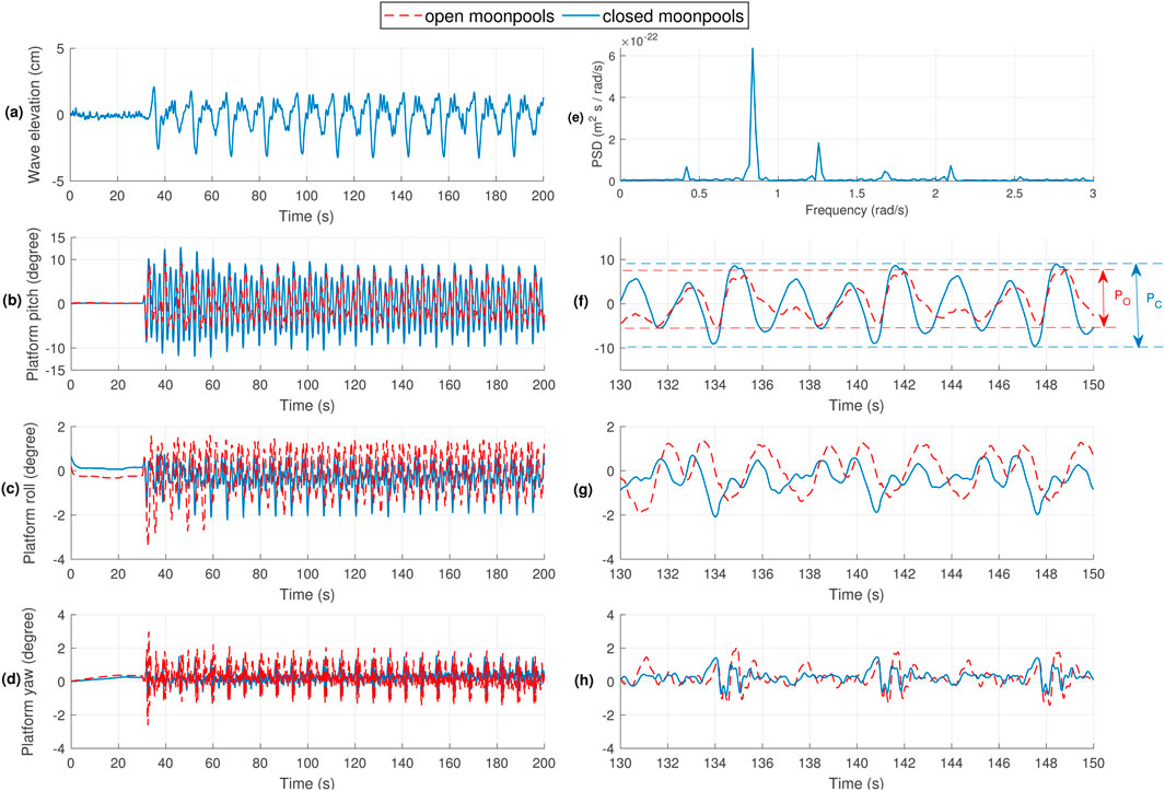
Figure 12. Experimental results for (A) Wave elevation (0s–200s), (B) Platform pitch (0s–200s), (C) Platform roll (0s–200s), (D) Platform yaw (0s–200s), (E) Wave power spectral density, (F) Platform pitch (130s–150s), (G) Platform roll (130s–150s), (H) Platform yaw (130s–150s).
Figures 12A, E represent the wave elevation (in centimeters) and the Power Spectral Density (PSD) of the wave, respectively. In terms of platform pitch, Figure 12B illustrates the distance between the highest wave crest and the lowest wave trough for the closed moonpool-based platform
Figures 12C, D showcase the platform roll angle and platform yaw angle, respectively. Both figures demonstrate relatively small oscillations for platform roll (between around −2° and 1°) and platform yaw (between around −1° and 2°), indicating that the impact of the irregular wave on these rotational modes is minor.
For better readability, Figure 12B shows the time range from 0s to 200s, while Figure 12F provides a zoomed-in view of the same data from 130s to 150s. Similarly, Figures 12C, D correspond to the zoomed-in view in Figures 12G, H respectively.
These model test results further validate the positive influence of OWCs in reducing platform pitch oscillations, enhancing the overall stability and performance of the barge-based FOWT system under wave-induced conditions. The promising outcomes pave the way for further optimization and implementation of OWCs in floating offshore wind turbine designs, potentially enhancing the reliability and efficiency of these renewable energy systems.
The RAO results for roll, yaw, and pitch responses of the floating platform are depicted in Figure 13 for two configurations: open-moonpools (dashed red line) and closed-moonpools (solid blue line). In the roll RAO (a), both configurations exhibit multiple resonance peaks, particularly around 1.5 s and 2.5 s periods, with minimal differences between the two setups. The yaw RAO (b) also shows peaks, but with lower magnitudes than roll, indicating less sensitivity to yaw motion, with the open-moonpools platform. In the pitch RAO (c), the pitch response is more significant, peaking sharply near 2 s and 3 s periods, where the open-moonpools configuration shows a noticeable reduction in response, especially between 1s and 2.5s, indicating superior pitch damping capabilities compared to the closed-moonpools platform.
5 Conclusion
This article focuses on mitigating oscillations in barge-type floating offshore wind turbines (FOWTs) when exposed to waves in the absence of wind. The study demonstrates that these oscillations can be effectively reduced by integrating oscillating water columns (OWCs) inside the barge platform. To achieve this, the barge platform was modified and equipped with OWCs. Initially, the equation of motion of the FOWT was described, followed by a numerical approach that explained the system’s behavior under various wave frequencies using response amplitude operators (RAOs). The RAOs were used to evaluate the rotational modes, including platform roll, yaw, and pitch. Based on the analyzed numerical results, a barge-based FOWT model was created, incorporating moonpools at the platform’s corners. Subsequently, benchmark tests were conducted on both the closed and open moonpool-based platforms to assess their performance and validate the excellence behavoir of the proposed OWC integration.
An irregular wave was considered for the numerical and experimental analysis. As explained in the numerical results section, the results showed that the platform pitch oscillations were lower for the open (14.381 deg.) vs the closed OWC-based barge platform (17.506 deg.). In agreement with these numerical results, a similar improvement was found in the experimental results, with a reduction in platform pitch oscillations for the open (18.41 deg.) vs the closed moonpool-based platform (12.23 deg.).
Data availability statement
The original contributions presented in the study are included in the article/supplementary material, further inquiries can be directed to the corresponding author.
Author contributions
PA: Conceptualization, Investigation, Methodology, Software, Validation, Writing–original draft, Writing–review and editing. AG: Conceptualization, Investigation, Methodology, Software, Validation, Writing–original draft, Writing–review and editing. JS-R: Conceptualization, Investigation, Methodology, Software, Validation, Writing–original draft, Writing–review and editing. IG: Conceptualization, Investigation, Methodology, Software, Validation, Writing–original draft, Writing–review and editing.
Funding
The author(s) declare that financial support was received for the research, authorship, and/or publication of this article. This work was supported in part by MICIN through PID 2021-123543OB-C21 and PID 2021-123543OB-C22 funded by MCIN/AEI/10.13039/501100011033, Basque Government through IT1555-22, and Margarita Salas grant MARSA22/09 by the European Union-Next Generation EU.
Conflict of interest
The authors declare that the research was conducted in the absence of any commercial or financial relationships that could be construed as a potential conflict of interest.
Publisher’s note
All claims expressed in this article are solely those of the authors and do not necessarily represent those of their affiliated organizations, or those of the publisher, the editors and the reviewers. Any product that may be evaluated in this article, or claim that may be made by its manufacturer, is not guaranteed or endorsed by the publisher.
References
Aboutalebi, P., Garrido, A. J., Garrido, I., Nguyen, D. T., and Gao, Z. (2024). Hydrostatic stability and hydrodynamics of a floating wind turbine platform integrated with oscillating water columns: a design study. Renew. Energy 221, 119824. doi:10.1016/j.renene.2023.119824
Aboutalebi, P., M’zoughi, F., Garrido, I., and Garrido, A. J. (2021a). Performance analysis on the use of oscillating water column in barge-based floating offshore wind turbines. Mathematics 9, 475. doi:10.3390/math9050475
Aboutalebi, P., M’zoughi, F., Garrido, I., and Garrido, A. J. (2022). A control technique for hybrid floating offshore wind turbines using oscillating water columns for generated power fluctuation reduction. J. Comput. Des. Eng. 10, 250–265. doi:10.1093/jcde/qwac137
Aboutalebi, P., M’zoughi, F., Martija, I., Garrido, I., and Garrido, A. J. (2021b). Switching control strategy for oscillating water columns based on response amplitude operators for floating offshore wind turbines stabilization. Appl. Sci. 11, 5249. doi:10.3390/app11115249
Ahmad, I., M’zoughi, F., Aboutalebi, P., Garrido, I., and Garrido, A. J. (2023a). Fuzzy logic control of an artificial neural network-based floating offshore wind turbine model integrated with four oscillating water columns. Ocean. Eng. 269, 113578. doi:10.1016/j.oceaneng.2022.113578
Ahmad, I., M’zoughi, F., Aboutalebi, P., Garrido, I., and Garrido, A. J. (2023b). A regressive machine-learning approach to the non-linear complex fast model for hybrid floating offshore wind turbines with integrated oscillating water columns. Sci. Rep. 13, 1499. doi:10.1038/s41598-023-28703-z
Amundarain, M., Alberdi, M., Garrido, A. J., and Garrido, I. (2010). Modeling and simulation of wave energy generation plants: output power control. IEEE Trans. Industrial Electron. 58, 105–117. doi:10.1109/tie.2010.2047827
Aubault, A., Alves, M., Sarmento, A. n., Roddier, D., and Peiffer, A. (2011). Modeling of an oscillating water column on the floating foundation windfloat. Int. Conf. Offshore Mech. Arct. Eng. 44373, 235–246. doi:10.1115/OMAE2011-49014
Chen, Z., Sun, J., Yang, J., Sun, Y., Chen, Q., Zhao, H., et al. (2024). Experimental and numerical analysis of power take-off control effects on the dynamic performance of a floating wind-wave combined system. Renew. Energy 226, 120353. doi:10.1016/j.renene.2024.120353
Cutler, J., Bashir, M., Yang, Y., Wang, J., and Loughney, S. (2022). Preliminary development of a novel catamaran floating offshore wind turbine platform and assessment of dynamic behaviours for intermediate water depth application. Ocean. Eng. 258, 111769. doi:10.1016/j.oceaneng.2022.111769
Dong, X., Li, Y., Li, D., Cao, F., Jiang, X., and Shi, H. (2022). A state-of-the-art review of the hybrid wind-wave energy converter. Prog. Energy 4, 042004. doi:10.1088/2516-1083/ac821d
Fu, S., Jin, Y., Zheng, Y., and Chamorro, L. P. (2019). Wake and power fluctuations of a model wind turbine subjected to pitch and roll oscillations. Appl. Energy 253, 113605. doi:10.1016/j.apenergy.2019.113605
Garrido, A. J., Garrido, I., Amundarain, M., Alberdi, M., and De la Sen, M. (2012). Sliding-mode control of wave power generation plants. IEEE Trans. Industry Appl. 48, 2372–2381. doi:10.1109/tia.2012.2227096
Ghafari, H. R., Ghassemi, H., and Neisi, A. (2022). Power matrix and dynamic response of the hybrid wavestar-deepcwind platform under different diameters and regular wave conditions. Ocean. Eng. 247, 110734. doi:10.1016/j.oceaneng.2022.110734
Haji, M. N., Kluger, J. M., Sapsis, T. P., and Slocum, A. H. (2018). A symbiotic approach to the design of offshore wind turbines with other energy harvesting systems. Ocean. Eng. 169, 673–681. doi:10.1016/j.oceaneng.2018.07.026
Hu, J., Zhou, B., Vogel, C., Liu, P., Willden, R., Sun, K., et al. (2020). Optimal design and performance analysis of a hybrid system combing a floating wind platform and wave energy converters. Appl. energy 269, 114998. doi:10.1016/j.apenergy.2020.114998
Jahangiri, V., Sun, C., and Kong, F. (2021). Study on a 3d pounding pendulum tmd for mitigating bi-directional vibration of offshore wind turbines. Eng. Struct. 241, 112383. doi:10.1016/j.engstruct.2021.112383
Jahani, K., Langlois, R. G., and Afagh, F. F. (2022). Structural dynamics of offshore wind turbines: a review. Ocean. Eng. 251, 111136. doi:10.1016/j.oceaneng.2022.111136
Jonkman, J. M. (2007). Dynamics modeling and loads analysis of an offshore floating wind turbine. United States: University of Colorado at Boulder.
Kampitsis, A., Kapasakalis, K., and Via-Estrem, L. (2022). An integrated fea-cfd simulation of offshore wind turbines with vibration control systems. Eng. Struct. 254, 113859. doi:10.1016/j.engstruct.2022.113859
Kluger, J. M., Slocum, A. H., and Sapsis, T. P. (2017). “A first-order dynamics and cost comparison of wave energy converters combined with floating wind turbines,” in The 27th international ocean and polar engineering conference (OnePetro).
Lackner, M. A. (2013). An investigation of variable power collective pitch control for load mitigation of floating offshore wind turbines. Wind energy 16, 435–444. doi:10.1002/we.1502
Lee, C., and Newman, J. (2013). Wamit user manual. Chestnut Hill, Massachusetts: WAMIT Inc. version 7.0.
Maxwell, S. M., Kershaw, F., Locke, C. C., Conners, M. G., Dawson, C., Aylesworth, S., et al. (2022). Potential impacts of floating wind turbine technology for marine species and habitats. J. Environ. Manag. 307, 114577. doi:10.1016/j.jenvman.2022.114577
Moghimi, M., Derakhshan, S., and Motawej, H. (2020). A mathematical model development for assessing the engineering and economic improvement of wave and wind hybrid energy system. Iran. J. Sci. Technol. Trans. Mech. Eng. 44, 507–521. doi:10.1007/s40997-018-0272-8
M’zoughi, F., Aboutalebi, P., Garrido, I., Garrido, A. J., and De La Sen, M. (2021). Complementary airflow control of oscillating water columns for floating offshore wind turbine stabilization. Mathematics 9, 1364. doi:10.3390/math9121364
M’zoughi, F., Bouallegue, S., Garrido, A. J., Garrido, I., and Ayadi, M. (2018). Fuzzy gain scheduled pi-based airflow control of an oscillating water column in wave power generation plants. IEEE J. Ocean. Eng. 44, 1058–1076. doi:10.1109/joe.2018.2848778
Nazokkar, A., and Dezvareh, R. (2022). Vibration control of floating offshore wind turbine using semi-active liquid column gas damper. Ocean. Eng. 265, 112574. doi:10.1016/j.oceaneng.2022.112574
Palraj, M., and Rajamanickam, P. (2020). Motion control of a barge for offshore wind turbine (owt) using gyrostabilizer. Ocean. Eng. 209, 107500. doi:10.1016/j.oceaneng.2020.107500
Pérez-Collazo, C., Greaves, D., and Iglesias, G. (2015). A review of combined wave and offshore wind energy. Renew. Sustain. energy Rev. 42, 141–153. doi:10.1016/j.rser.2014.09.032
Pintelon, R., and Schoukens, J. (2012). System identification: a frequency domain approach. John Wiley and Sons.
Ren, N., Ma, Z., Shan, B., Ning, D., and Ou, J. (2020). Experimental and numerical study of dynamic responses of a new combined tlp type floating wind turbine and a wave energy converter under operational conditions. Renew. Energy 151, 966–974. doi:10.1016/j.renene.2019.11.095
Sarkar, S., and Fitzgerald, B. (2022). Fluid inerter for optimal vibration control of floating offshore wind turbine towers. Eng. Struct. 266, 114558. doi:10.1016/j.engstruct.2022.114558
Sarmiento, J., Iturrioz, A., Ayllón, V., Guanche, R., and Losada, I. (2019). Experimental modelling of a multi-use floating platform for wave and wind energy harvesting. Ocean. Eng. 173, 761–773. doi:10.1016/j.oceaneng.2018.12.046
Sebastian, B., Karmakar, D., and Rao, M. (2024). Coupled dynamic analysis of semi-submersible floating wind turbine integrated with oscillating water column wec. J. Ocean Eng. Mar. Energy 10, 287–312. doi:10.1007/s40722-023-00313-x
Wei, X., and Zhao, X. (2020). Vibration suppression of a floating hydrostatic wind turbine model using bidirectional tuned liquid column mass damper. Wind Energy 23, 1887–1904. doi:10.1002/we.2524
Xilin, Z., Xin, W., and Zhimin, W. (2004). Research on wind/photovoltaic/wave energy hybrid system applications on islands. Renew. Energy 2, 42–44.
Yang, J., He, E., and Hu, Y. (2019). Dynamic modeling and vibration suppression for an offshore wind turbine with a tuned mass damper in floating platform. Appl. Ocean Res. 83, 21–29. doi:10.1016/j.apor.2018.08.021
Keywords: barge-based floating offshore wind turbie, experimental tests, oscillations evaluation, oscillating water column, hybrid system
Citation: Aboutalebi P, Garrido AJ, Schallenberg-Rodriguez J and Garrido I (2024) Validation of vibration reduction in barge-type floating offshore wind turbines with oscillating water columns through experimental and numerical analyses. Front. Built Environ. 10:1497123. doi: 10.3389/fbuil.2024.1497123
Received: 16 September 2024; Accepted: 21 October 2024;
Published: 05 November 2024.
Edited by:
Majid Movahedi Rad, Széchenyi István University, HungaryReviewed by:
Hua-Yi Peng, Harbin Institute of Technology, ChinaOveys Ghodousian, Takestan Islamic Azad University, Iran
Copyright © 2024 Aboutalebi, Garrido, Schallenberg-Rodriguez and Garrido. This is an open-access article distributed under the terms of the Creative Commons Attribution License (CC BY). The use, distribution or reproduction in other forums is permitted, provided the original author(s) and the copyright owner(s) are credited and that the original publication in this journal is cited, in accordance with accepted academic practice. No use, distribution or reproduction is permitted which does not comply with these terms.
*Correspondence: Payam Aboutalebi, cGF5YW0uYWJvdXRhbGViaUBlaHUuZXVz
 Payam Aboutalebi
 Aitor J. Garrido1