 Gamil Ahmed
 Tarek Sheltami
 Ashraf Mahmoud1
 Ansar Yasar
- 1Computer Engineering Department, Interdisciplinary Research Center of Smart Mobility and Logistics, King Fahd University of Petroleum and Minerals, Dhahran, Saudi Arabia
- 2Transportation Research Institute (IMOB), Hasselt University, Hasselt, Belgium
Vehicle ad hoc networks (VANETs) have gradually emerged to enhance transportation information, entertainment, safety, and other services. However, such infrastructures have certain limitations, causing intermittent network disconnection. Further, in urban areas, terrain heights act as obstacles and hinder or attenuate transmitted signals. In this study, we propose a dynamic 3D internet of drones collaborative communication approach for efficient VANET-assistance (3DIoDAV) by integrating the IoD network and VANET to support terrestrial communication. We model IoD locations as an optimization problem to optimize the IoD nodes in three-dimensional terrain. Improved particle swarm optimization is used to optimally deploy IoD nodes in 3D terrain for minimizing the number of isolated vehicles. The proposed approach considers the terrain profile influence on communication. Therefore, we propose a 3D propagation model for efficient IoD-to-vehicle (IoD2V) communication in 3D space. Experiments are performed based on the received signal from ground vehicles to examine the performance of the proposed model and the 3DIoDAV approach. Simulation results show different behaviors of IoD nodes in two-dimensional (2D) and 3D scenarios. Comparison with 2D VANET-assisted and IoDAV approaches demonstrates the proposed 3DIoDAV approach’s ability to detect terrain obstacles, which guarantees the dispatching of IoD nodes into the most appropriate locations in 3D space, thereby minimizing the impact of terrain obstacles on communication.
1 Introduction
Vehicle ad hoc networks (VANETs) have gradually emerged as a leading technology to deliver data from/to ground vehicles for real-time transportation information, entertainment, safety, and control Sami et al. (2023); Su et al. (2023); Azzoug and Boukra (2022). The design of an efficient communication system has certain limitations, such as heterogeneity, high mobility, and channel variation. To overcome these limitations, a dedicated base station (BS) was established at the road edge using a roadside unit (RSU) Andreou et al. (2023); Manzoor et al. (2021); Xu et al. (2021); Kim et al. (2022); Lee et al. (2023). However, a fixed RSU is limited by environmental constraints that reduce the probability of the line-of-sight (LoS) condition. This is addressed by increasing the number of RSUs, which incurs a high deployment cost. Moreover, vehicles in VANETs follow a restricted road and communicate with each other and with stationary stations alongside. This dynamic movement of vehicles causes frequent topology changes; therefore, the connectivity of numerous vehicles is intermittent (Lin et al., 2020; Zhu et al., 2021); Raja et al. (2021); Yang and Zhang (2021).
Recently, the internet of drones (IoD) has attracted considerable attention due to its unique features such as agility, mobility, and quick deployment. It can be integrated with other architectures to realize several applications, such as telecommunication, military, rescue, search, and monitoring. The unique features of IoD facilitates navigation in rough and remote areas that cannot be accessed by humans (Ahmed et al., 2020; Ahmed G. et al., 2021). IoD can achieve better LoS conditions for ground users than static infrastructures on the ground when acting as a relay network Islam et al. (2022). Therefore, it enables effective and efficient temporary communication during emergencies when terrestrial infrastructures are damaged or unavailable. Owing to the distinctive traits of the IoD paradigm, vehicle-to-vehicle communication, a type of device-to-device communication (Khoshafa et al., 2020), can be enhanced by deploying a swarm of unmanned aerial vehicles (UAVs) as a relay network to establish reliable wireless communication between vehicles in VANETs Mokhtari et al. (2022).
The IoD network deployment has been studied to solve coverage problems. Although deploying IoD at a higher altitude provides a better LoS condition, it increases the distance between the IoD network and ground vehicles, thereby increasing the path loss. Besides, terrain features remarkably impact the IoD-to-vehicle (IoD2V) communication as the height of the terrain acts as an obstacle and causes signal attenuation. Consequently, IoD2V communication is affected by multipath propagation. To improve the communication quality of a model involving IoD and vehicles, extensive simulation studies have been conducted for scale analysis Hadiwardoyo et al. (2018). In most existing studies, the simulations are performed in a two-dimensional (2D) environment, and the effect of terrain altitude on communication is neglected. However, the terrain is not perfectly flat as some roads descend or ascend. Particularly, some streets are separated by hills, which may yield different VANET communication results when terrain altitude is neglected Hadiwardoyo et al. (2018).
To address the aforementioned challenges, we propose an efficient IoD-assisted VANET approach in three-dimensional space (3DIoDAV) to enhance communication between ground vehicles. To achieve this, IoD nodes are optimally deployed to maximize the number of covered vehicles, i.e., reducing the number of isolated vehicles. Moreover, the impact of the terrain profile on communication is addressed by proposing a three-dimensional (3D) propagation model for IoD2V communication to enhance the communication quality between IoD in the air and vehicles on the ground. Population-based metaheuristic search algorithms, such as particle swarm optimization (PSO) and ant colony (ACO), have been widely applied to various problems Waleed et al. (2021). In this study, the proposed approach employs improved version of PSO (IPSO) algorithm for deployment, where the optimal deployment of IoD nodes is obtained by implementing IPSO. The proposed 3D propagation model is added to the objective function to evaluate the signal quality of ground vehicles (i.e., receiver’s end), in which the effect of high-level terrain on communication is considered while calculating the received signal strength. Consequently, IoD nodes are dispatched to the most appropriate locations that minimize the impact of terrain obstacles on transmitted signals and ameliorate the LoS condition between the sender and receiver. In this study, the terms IoD altitude and deployment altitude are used interchangeably. Also, the terms UAV and drone are used interchangeably.
The major contributions of this study are the following.
• A novel IoD2V communication model is proposed to characterize the 3D communication between the IoD network and ground vehicles. The proposed model considers the terrain profile to detect obstacles and evaluates the quality of the received signal accordingly.
• A novel 3D collaborative IoD architecture is proposed to maximize the coverage area and enhance the quality of the received signal at a receiver’s end. The demand for drones is evaluated using an optimization evaluation function to obtain the optimal IoD deployment to assist VANETs.
• A population optimization scheme is employed to dispatch IoD nodes at optimal locations in 3D space based on the locations of ground vehicles, such that the connectivity of vehicles and received signal quality are improved. To achieve this objective, we implement IPSO such that an adequate signal is guaranteed toward isolated vehicles. Further, the proposed 3D propagation model is used by the objective function of IPSO, such that the impact of terrain on communication is considered in IoD deployment.
• The performances of the proposed IoD2V communication model and 3DIoDAV approach are tested via simulations.
The remainder of this article is organized as follows. Section 2 presents the state of the art in this research field. In Section 3, we discuss the IoD2V communication model. Section 4 thoroughly describes the 3DIoDAV approach, including the optimal IoD deployment in 3D terrain, the formulation of 3DIoD-assisted VANET, the optimization problem, and the optimization framework. In Section 5, the simulation results and corresponding analysis are presented. Finally, conclusions are drawn in Section 6.
2 State of the art
Recent studies have investigated the integration of UAVs and ground networks, i.e., UAV-assisted, deployment, to enhance the ground network performance, including the target area coverage and received signal strength (RSS). Particularly, drone-to-vehicle communications have been addressed using simulations; however, these simulations were performed assuming flat scenarios, where the effect of 3D communication between UAVs and ground networks is neglected. Few studies have considered the impact of the terrain in their simulations. Without loss of generality, the related work is classified based on the propagation model used in UAV-assisted deployment, namely, 2D and 3D UAV-assisted deployment.
2.1 2D UAV-assisted deployment
UAV-assisted deployment can provide connectivity and communication for ground users by acting as wireless BS or RSU, particularly when the terrestrial infrastructure capacity is insufficient. Further, the deployment of ground BSs becomes inefficient and difficult under harsh and remote environments. To extend the coverage in such environments, UAVs-assisted deployment can be employed.
The authors of (Mozaffari et al., 2016) proposed a deployment strategy where UAVs act as wireless BSs to ensure good coverage for ground users. The download coverage probability was defined as a function of the antenna gain and UAV height. Moreover, the objective was to calculate the 3D positions of UAVs that maximize the drone lifetime, and maximum coverage was achieved across the entire region. However, the height of the drone position must be defined based on the coverage requirement and the beam-width of the directional antenna. Jiang et al., 2018) formulated a UAV placement strategy as a maximization optimization problem. Particularly, the throughput and coverage were optimized considering the UAV memory constraint. Hence, the optimal drone location was determined, and the optimal caching strategy was solved.
He et al. (2018) implemented PSO to determine the optimal placement of UAVs. The objective was to maximize the coverage area while considering the UAV capacity within the scope of public safety and disaster management. Tuba et al. (2017) calculated the optimal position of UAVs to improve the network coverage quality using a brainstorm optimization algorithm. Further, (Sabino et al., 2018), proposed an optimization approach to cover all targets on the ground while minimizing data discrepancy among end devices and their communication services using the available UAVs.
In (Yang et al., 2018), the optimal UAV flight path was obtained using multiobjective bioinspired algorithms. Several objectives were included, such as sensing ability, energy, flight time, and associated risk. Moreover, (Gupta et al., 2021), used the available UAVs to obtain their optimal heights in a 3D environment. Particularly, the quality of service (QoS), energy consumption, and target coverage were targeted objectives for optimization. The UAV connectivity was maintained using a grid-based connectivity network. However, they only consider static coverage, where UAVs hover at a given target area and cover static targets. Further, the drones altitude were optimized for generating a near-optimal height to cover the target devices and achieve the minimum energy consumption of transmitted data and QoS. In urban terrain, vehicle communication and movement are constrained by buildings and infrastructure (Sommer et al., 2011). A significant improvement in VANET connectivity is achieved when using drones as flying RSUs. This is due to the ability of UAVs to fly at a high altitude beyond terrestrial infrastructures, facilitating UAV movement to be less influenced by terrestrial constraints, and its transmission less influenced by terrestrial obstacles.
Several approaches have been proposed regarding UAV deployment for VANETs’ communication. Oubbati et al. (2019) proposed an urban VANET routing solution to ensure reliable paths as alternatives in case the main path fails. Further, (Oubbati et al., 2019), deployed UAVs to detect incidents on an urban road. The aim of the UAV deployment was to provide vehicle emergency guidance. In addition, a hybrid of drone and ad hoc networks was designed to reduce the end-to-end delay among vehicles (Wang et al., 2016). Lin et al. (2018) studied the deployment of long-term evolution connectivity for UAVs. They highlighted several challenges, including LoS propagation in the sky. In (Seliem et al., 2018), the packet delivery ratio was improved and the end-to-end delay in a ground network was reduced using a drone. In (Oubbati et al., 2017), the distribution and stability of vehicles were achieved by selecting the optimal path created by drones as an alternative path.
In Ahmed et al. (2021b), a novel IoD collaborative communication approach was proposed to improve communication among VANETs. UAVs were optimally deployed to maximize the coverage area and improve the quality of the received signal. Although the proposed approach achieved an optimal coverage area, the simulation was performed assuming a flat area, and the impact of high-level terrain was neglected. Raza et al. (2021) proposed a UAV-assisted VANET for safety in an intelligent transportation system. Furthermore, they highlighted the challenges in traditional VANETs. A highway scenario was considered in the simulation, and the vehicles’ velocities, densities, and length of the road were analyzed.
2.2 3D UAV-assisted deployment
In this subsection, we review the related work on UAV-assisted VANET that considered the effect of terrain elevation on communication.
Hadiwardoyo et al. (2018) proposed a digital elevation model (DEM) to detect obstacles formed by the terrain. Moreover, to evaluate the performance of the aerial platform, three propagation models were employed, namely, the single knife-edge, Deygout, and Bullington models, which support mobile vehicles to broadcast alerts in emergencies. Two altitudes, 40 and 100-m, were tested. The simulation obtained reasonable results for 100-m altitudes. However, the scenario included only one vehicle moving on the ground and one drone hovering at the same position. In Hadiwardoyo et al. (2019), the optimal UAV deployment to provide 3D communication between a UAV and three ground vehicles was proposed. PSO was used to obtain the optimal position of the UAV such that sufficient RSS was maintained at the receivers’ end. The simulation included DEM, indicating terrain obstacles, to test the 3D communication performance. The implementation comprised three vehicles moving on the ground and one drone placed at the optimal location. A swarm of drones was not considered in these studies.
In conclusion, several previous studies have enhanced the performance of VANET, in terms of routing, coverage area maximization, RSS, end-to-end delay, and throughput. Some studies have focused on VANET communication enhancement. However, simulations were performed in a 2D environment, and the effect of terrain profile on communication was neglected. Although few studies have considered the effect of terrain on communication, they neglected IoD formation and focused on using only one UAV. Generally, the superiority and flexibility of IoD formation have not been fully exploited to improve VANET communication in 3D space.
Herein, we design a 3D IoD-assisted VANET to boost communication performance in 3D space. Terrain obstacles are considered for IoD2V communication. Based on this, we propose a 3D propagation model used in the simulation to include terrain obstacles when calculating the received signal on the receivers’ side. IoD nodes are dynamically dispatched to the optimal position in real time. Such real-time deployment is based on the distribution of ground vehicles and the terrain obstacles between IoD nodes and VANETs. This deployment maximizes the number of covered vehicles and reduces the number of isolated vehicles in a 3D environment. Furthermore, the IoD node deployment is adjusted to adopt the dynamic movement of ground vehicles.
The optimization technique (IPSO) is employed for optimal IoD deployment, such that the best coverage is obtained at each specific time. In this study, coverage is measured by the number of ground vehicles covered by IoD. The main assumption is that the connectivity among vehicles is at its minimum due to the lack of infrastructure in the terrain. For example, an LoS might be hindered by mountains and hills, thereby disrupting connection among vehicles. The UAV aims to provide connectivity among isolated vehicles by exploring a 3D space and being deployed at most appropriate locations.
3 IoD-to-vehicles communication model in 3D environment
The proposed IoD2V communication model aims to support communication among vehicles in an environment where infrastructures are limited and terrain irregularities impact communication between nodes. In rural areas, the main challenge is the terrain profile, especially if it includes hills and mountains acting as obstacles, thereby attenuating the transmitted signal. Thus, obstacle detection is necessary to characterize communication in such an environment. To this end, the terrain elevation is extracted to evaluate the IoD2V communication where the high elevation of the terrain can act as an obstruction to communication. In this section, the DEM and 3D propagation model are thoroughly described.
3.1 Digital elevation model (DEM)
Terrestrial surface information can be acquired owing to advances in satellite technology. Moreover, the exploitation of radar grametertics, stereo graphics, LiDAR, and interferometric principles generate DEM at multiple temporal and spatial scales Hadiwardoyo et al. (2018). The Earth surface is presented by a DEM and is available for download from USGS. Further, the DEM provides information about the Earth’s surface and can be used to recognize the height of terrain above sea level. The elevation of any point can be obtained from different sources within USGS. An interesting documented source is based on the Shuttle Radar Topology Mission (SRTM). In particular, a NASA DEM, which is collected from the SRTM, is employed Drusch et al. (2012). In this model, the Earth’s surface information is captured using a radar sensor from space. Various resolutions are supported, defining the elevation accuracy.
3.1.1 Structure of DEM file
The DEM file is in height format and named in the easting and northing format. The easting and northing mean the eastward and northward measure distances, respectively, when adapting the universal Transverse Mercator (UTM) system. The DEM covers one degree of latitude and longitude. Thus, the structure of the DEM file is a 2D array of cell points represented as grids. Besides, two resolutions are provided: 3 and 1-arc second sampling. The elevation is extracted from the file by precisely selecting and pinpointing the suitable longitude and latitude into the right cell of the grid. The grids of 1-arc second sampling for obtaining the elevation data are illustrated in Figure 1. The figure shows that the grid comprises 3,601 × 3,601 cells and covers one degree of latitude and longitude. Each degree of latitude and longitude is represented by 3,601 cells. Moreover, each cell index can be obtained by multiplying the fraction part of the geographical coordinate by 3,600, i.e., 0.8 represents the 2,880th cell.

FIGURE 1. DEM data structure.
In this study, we consider a mountainous terrain, namely, Al-Hada Road, KSA terrain. The complete 3D view of the terrain is plotted using MATLAB (Figure 2). Different heights are discernible, representing elevations ranging from 758 to 2,608 m.

FIGURE 2. 3D view of Al-Hada Road from DEM file.
3.1.2 Elevation data extraction
In this subsection, we explain how to effectively extract elevation data from the DEM file. The DEM data cover a given latitude and longitude. However, the coordinates used for location are given in meters. Compared with the UTM system, the area provided by the DEM data provides a small tilled area. As illustrated in Figure 1, the DEM file portrays a 2D array with a constant distance between consecutive points along horizontal and vertical directions. Thus, it contains N×N elevation points that can be extracted into an N×N matrix. Each point represents the elevation on the z-axis. Notably, the x- and y-axis can be omitted without losing the information of any given point. The MATLAB function geotiffread (DEMfile.tif) is employed to extract the elevation of DEMfile.tif into a 2D matrix. The function also provides information on latitude and longitude limits.
3.2 3D propagation model
In this subsection, we describe the proposed 3D propagation model and show how the attenuation can be obtained based on the elevation information in the DEM file for a specific area. The quality of communication is affected by high terrain, which might obstruct the signal propagation. Non-LoS (NLoS) conditions can occur because of mountains and hills, which reduce the RSS or even block it. Notably, the diffraction effect due to high terrain deflects or bends signal waves. To analyze the diffraction effect, the obstacle can be approximated as a knife edge. In this case, the knife-edge diffraction attenuates the transmitted signal, and its effect can be calculated using parameters such as signal wavelength λ), obstacle height above the LoS between transmitter and receiver, and distance between the obstacle and transmitter and receiver. Further, the height of an obstacle above the LoS is retrieved from the elevation data in the DEM file. The LoS between the sender and receiver is obtained by considering two points in a 3D space. The first point is the sender’s position coordinate (xs, ys, zs), and the second point is the receiver’s position coordinate (zr, yr, zr). The prediction point can be determined and analyzed based on the number of slices that divide the LoS. With this in mind, the inspection points divide the LoS into slices (Figure 3). According to these points, there is only one line passing through them. The LoS is divided into discrete points to detect the terrain obstructing the signal and acting as an obstacle. At each point, the coordinate (xp, yp, zp) is obtained as in Hadiwardoyo et al. (2018) using
where Δ denotes the fraction of the LoS. Notably, Δ is selected such that the slices of the LoS are not higher or lower than the DEM file resolution. After calculating zp for each slice, the elevation of this position (Ep) is extracted using the DEM file and compared with zp. The height of the obstacle above the LoS is calculated using the following equation
The obstacle is detected if hp is positive, indicating that the height of the obstacle is above the LoS, whereas a negative value of hp indicates that no obstacle is detected. In this study, we use a single knife-edge propagation model to evaluate signal attenuation.
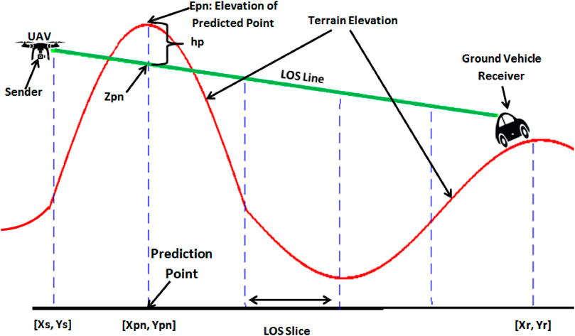
FIGURE 3. Dividing the LoS between sender and receiver into a set of prediction points for obstacle detection.
3.3 Single knife-edge propagation model
In the single knife-edge model, after obtaining the obstacle height (hp), a Fresnel–Kirchhoff diffraction parameter (vh) is evaluated. The diffraction parameter is a function of the obstacle height, distance between the sender and obstacle (Ds), distance between obstacle and receiver (Dr), and wavelength of the signal (λ). Hence, the diffraction parameter vh can be calculated as follows Lee (1998):
Then, signal attenuation is calculated using the Fresnel integral η(vh) as a function of vh. The Fresnel integral is obtained as follows Lee (1998):
After obtaining the Fresnel integral, signal attenuation can be evaluated as follows (in dBm):
4 3DIoDAV
As highlighted in Section 2, previous studies on VANETs intended to improve VANET performance, whereas UAV mobility superiority was neglected. Further, the impact of terrain features on the communication between IoD and VANET was also omitted. Although some scholars have considered the influence of terrain features on communication, they used only one drone in a simple scenario of one or three vehicles, failing to consider IoD flexibility and mobility superiority. Integrating several UAVs in a wide area with VANETs can dispense several infrastructures. Moreover, terrain obstacles can be detected and included to determine the effect of terrain on communication. Thus, the proposed IoD2V communication model is used in IoD-assisted deployment to properly calculate signal attenuation due to terrain obstacles.
As illustrated in Figure 4, the proposed 3DIoDAV architecture comprises the IoD network and VANET. The mobility of vehicles in the VANET is restricted by predefined paths. Further, the communication quality of vehicles is influenced by hills and mountains, which act as obstacles and might block the transmitted signal. The IoD network, comprising a swarm of UAVs with wireless communication, is responsible for supporting communication between ground vehicles. Owing to the flexibility and mobility of UAVs in the IoD network, they are easily deployed to their optimal locations and act as a relay-assisted network. The proposed 3D propagation model for IoD2V communication is used to characterize communication between IoD nodes and vehicles.
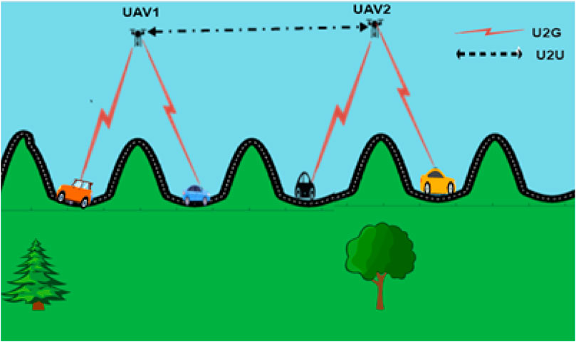
FIGURE 4. 3D IoD-assisted VANET communication architecture where UAVs flying in the urban and provide communication facilities to underneath vehicles. They also have inter-UAV communication links. Architecture.
Figure 4 illustrates the effectiveness of the proposed architecture where vehicles cannot communicate directly within their communication range due to hills and mountains obstructing the transmitted signal. Owing to the proposed 3DIoDAV, UAV1 and UAV2 are dispatched to suitable positions and act as relay nodes to provide a communication line between isolated vehicles. Notably, the drone locations are updated periodically based on the locations of ground vehicles and the RSS state therein. As the vehicles move, the distance between them increases, and the obstacles lying between them might isolate them from other vehicles, thereby causing a loss of connection. The proposed approach aims to dynamically connect isolated vehicles at each time step. In the following subsections, we will explain in details the optimal IoD deployment in 3D terrain, and the optimization framework of the proposed approach.
4.1 Optimal IoD deployment in 3D terrain
This subsection describes how to optimize IoD deployment in 3D space as well as the employed optimization approach. In our previous study Ahmed G. A. et al. (2021), the dynamic deployment of the IoD network is considered where IoD nodes dynamically change their positions based on the locations of ground vehicles. The aim is to maximize the coverage area and enhance the quality of the received signal on the receiver’s end. However, the effect of terrain obstacles is not considered. The main objective of this study is to obtain the optimal location of IoD nodes in a 3D environment where the effect of terrain obstacles is considered when deploying IoD nodes. To this end, the proposed 3D propagation model for IoD2V communication is used to calculate the RSS on the receiver’s end. Notably, in the considered scenario, the IoD aids in relaying information among vehicles with limited infrastructure.
In the deployment, attempting all possible positions in 3D space to obtain the optimal positions is an inefficient approach that consumes a substantial amount of time, which is considered an NP-hard problem. A metaheuristic algorithm is a sophisticated solution to solve this problem, where the optimal solution is obtained without cycling through all possible locations. Instead, a solution is randomly generated and evaluated by a fitness function at each iteration, and the optimal solution is thus obtained. In our approach, we have employed IPSO Ahmed et al. (Dec. 2020). The cost function is updated by including the proposed 3D propagation model to evaluate the solution. The objective function obtains the RSS indicator (RSSI) at the receiver’s end and evaluates the generated positions of IoD nodes. Moreover, the coverage is then found based on the RSSI obtained by comparing it with a minimum power-level threshold, which we set to −89 dBm (the threshold for successful packet delivery). Based on the RSSI value, the number of covered vehicles is calculated, where a vehicle is considered covered if its received signal is greater than the minimum power-level threshold. The optimization algorithm used in this study is thoroughly explained in our previous work Ahmed G. A. et al. (2021), and also illustrated in Figure 5.
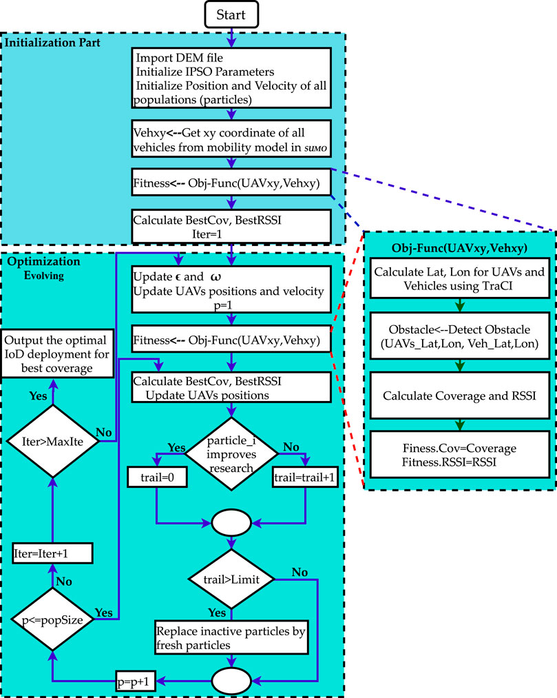
FIGURE 5. IPSO flow chart for 3D-IoD-assisted VANET description.
4.2 Optimization framework
In this subsection, we explain how to implement the proposed approach in a standard simulation tool. We aim to improve VANET connectivity in 3D space by deploying IoD nodes at optimal positions. To this end, the proposed 3D propagation model is employed in the objective function of IPSO to evaluate the quality of a generated solution. Notably, the proposed approach is implemented as an extension to OMNET++ (Varga et al., 2008), Veins (Sommer et al., 2010), and SUMO (Krajzewicz et al., 2012) by adding the 3D propagation model, where the physical layer is modified to simulate the effect of 3D wireless transmission. The main parameters that must be considered in the simulation are the terrain space and nodes locations (longitudes, latitudes, and altitudes).
The framework of the proposed mechanism is described in Figure 5, and illustrated in Figure 6. The proposed 3D propagation model comprises elevation estimation, obstacle detection, and propagation (single knife-edge) modules. The elevation estimation module is responsible for estimating the elevation of a given coordinates. The obstacle detection module receives the locations of senders and receivers and detects the obstacles lying between them. After detecting the obstacles and determining their heights, the module finds the maximum height and delivers it to the propagation module to calculate the signal attenuation. Figure 6 shows how the parameters are implemented in Veins.

FIGURE 6. 3D IoD-assisted VANET framework.
To obtain optimal VANET-assisted deployment of the IoD network in 3D space, the proposed approach works as follows. Terrain elevation information is extracted from the DEM file. The main challenge of using the entire DEM file is the long simulation time. To optimize the simulation time, we employed the MATLAB software function geotiffread to handle the geographical data. The function can read the downloaded DEMfile.tif and export the limits of longitude and latitude as well as the terrain elevation data. The elevation data are exported as a 2D array that can be stored as a. txt file. To save computation time, the text file is stored locally in the OMNET++ simulator.
Owing to TraCI in SUMO, the exact geographical coordinates of ground vehicles can be easily generated. Hence, connecting the Veins simulator with TraCI in SUMO allows obtaining the exact geographical coordinates of vehicles according to their mobility. Then, the implemented elevation estimation module determines the elevation of the transmitter and receiver. Moreover, the obstacle detection module detects the obstacles lying between the transmitter and receiver. Subsequently, the actual signal loss is better determined by the propagation module. Finally, the obtained signal strength is evaluated by the objective function of IPSO, and the optimal deployment of IoD nodes is obtained.
Considering the aforementioned illustration, IoD deployment acquires current locations of ground vehicles and finds the most appropriate positions of IoD nodes to enhance the RSS and minimize the number of isolated vehicles, i.e., maximize the number of covered vehicles. The IPSO objective function evaluates the received signal quality at the receiver’s end, which is obtained by the proposed 3D propagation model. The output of the IPSO algorithm is the IoD nodes’ optimal locations, such that the number of covered vehicles is maximized in 3D space.
5 Simulation results and discussion
We demonstrate the effectiveness of the proposed 3D propagation model to characterize IoD2V communication by illustrating its ability to detect obstacles between senders and receivers. This helps to properly calculate the coverage and quality of the received signal at the receiver’s end. Furthermore, we illustrate the effectiveness of the 3DIoDAV approach for improving the performance of VANET by achieving optimal coverage and maximum RSS. The impact of UAVs’ altitude, transmission power, and IoD size on coverage and RSSI are analyzed. Results are compared with a 2D model where only the free space propagation model is considered. We also compare our results with those of IoDAV Ahmed G. A. et al. (2021) to demonstrate the necessity of the proposed 3D propagation model for IoD2V communication for obtaining practical results.
Considering the goal of the proposed approach to produce realistic results and improve VANET connectivity, mean coverage, and mean RSSI are the adopted performance metrics in the simulation. Without loss of generality, the coverage is normalized to unity.
5.1 Simulation parameter settings
To implement the proposed 3DIoDAV, the mountainous rural area of Al-Hada Road, Attaif, KSA, is selected as the simulation terrain. The terrain map was imported from the open street map Haklay and Weber (2008) to render the simulation realistic. The elevation information of the terrain is obtained using SRTM DEM Drusch et al. (2012). In this area, communication might be hindered due to the height of obstacles in the terrain. The geographical area spans 6,000 × 8,000 m2, which is the limit of the exploration area. Further, a basic safety message (BSM) comprised a UDP packet with a size of 1.4 kB. We performed two simulations. The first simulation evaluates the proposed 3D propagation model, i.e., the IoD2V communication model, whereas the second one demonstrates the effectiveness of the 3DIoDAV approach in improving VANET performance. The durations of Simulations 1 and 2 to test the model’s behavior are limited to 1,040 and 600 s, respectively, after which most vehicles reach their destinations, to test the model’s behavior. The simulation parameters are listed in Table 1.
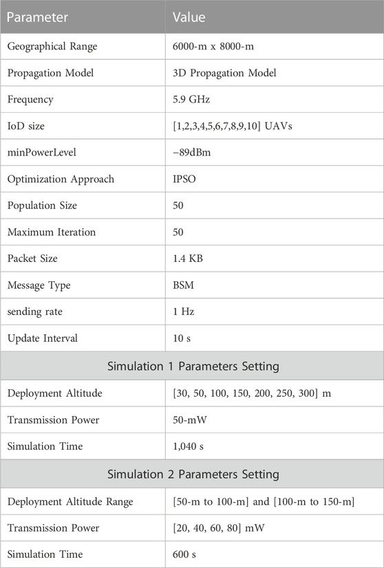
TABLE 1. Parameters setting.
The IoD network is deployed to support the wireless connectivity of ground vehicles. The coverage is obtained as a percentage of connected vehicles to total vehicles on the ground and can be obtained using Vcon/Vt (proposed in Ahmed G. A. et al. (2021)), where Vcon is the number of connected vehicles, and Vt is the total number of ground vehicles. Notebly, the specifications listed in Table 1, especially packet size, message type, sending rate, and update interval, and frequency are based on the following researches: Ahmed G. A. et al. (2021); Hadiwardoyo et al. (2018).
5.2 Evaluation of the proposed 3D propagation model for IoD2V communication
We validate the obtained results using the proposed framework, including the 3D communication model, with the results obtained from the 2D propagation model that neglects the terrain contribution. As the main goal is to analyze the impact of the 3D communication model, we use the simplest diffraction model, namely, a single knife-edge diffraction model. Further, we simulate different IoD deployment altitudes.
To assess the quality of the proposed communication model, we obtain the coverage with respect to simulation time for two altitudes (50 and 200-m) under the same setting parameters. To validate the proposed communication model and obtain an enhanced comparison, we compare the results with the 2D propagation model, i.e., the effect of terrain elevation is neglected, using the same setting parameters. The results are illustrated in Figures 7A, B for the proposed 3D and 2D propagation models, respectively.
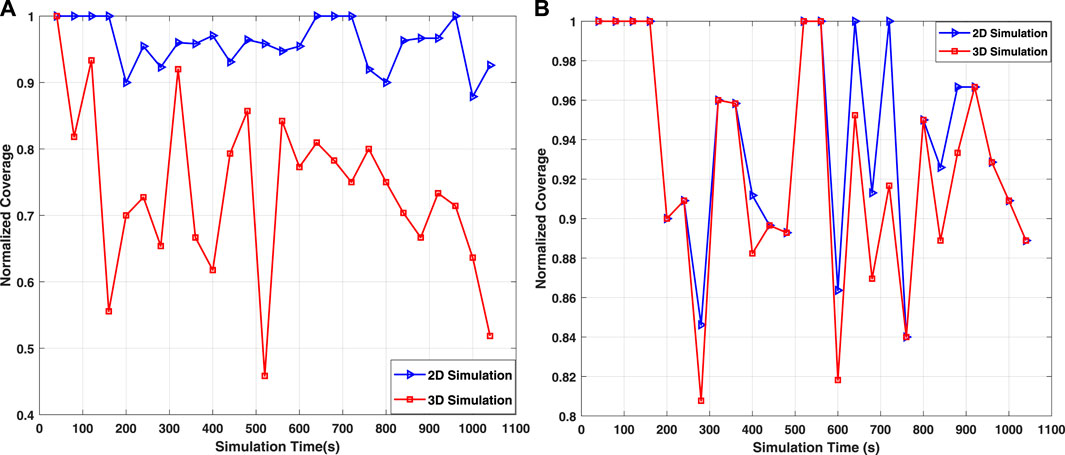
FIGURE 7. Average normalized coverage with respect to simulation time for two IoD deployment altitudes in the 2D and 3D propagation models. (A) 50-m deployment altitude, (B) 200-m deployment altitude.
When drones fly at 200-m altitude, the LoS condition is satisfied in most cases, and no considerable difference is observed. A slight difference is observed for the simulation times of 280, 400, and 600 s as the proposed 3D model yields lower coverage due to the terrain obstacles lying between some senders and receivers. The transmitted signal is completely obstructed and fails to reach some vehicles that become isolated, thereby reducing the coverage. In another scenario, where the drones are optimally deployed at 50-m altitude, the impact of using our proposed model is notable on coverage and RSSI. The elevation of the terrain obstructs the communication between IoD nodes and some ground vehicles; only 77.4% of total vehicles are covered in the proposed 3D communication model, in contrast to 96.5% of total vehicles covered in the 2D propagation model, indicating that the former shows an acceptable level of realism because the impact of terrain elevation on communication has been considered.
The average RSSI is recorded to further analyze the proposed 3D propagation model; the results are shown in Figures 8A, B for the altitudes of 50 and 200-m, respectively. Figure 8B explains why the coverage is reduced at the simulation times of 280, 400, and 600 s. The simulation highlights that RSS decreases at the same simulation time, where the lower value of RSSI is presented at 400 s at about −85 dBm. At this simulation time, the signal is obstructed by high terrain, resulting in a higher loss and lower percentage of covered vehicles than that in other simulation time. However, at other simulation times, the proposed 3D communication model and the 2D propagation model exhibit similar results. For lower altitude deployment, i.e., at 50-m, the signal is subjected to the NLoS condition in most cases (Figure 8A). Compared with the coverage results, the proposed 3D communication model yields significantly lower RSSI at 520 s. The average RSSI drops to about −88 dBm compared with the 2D propagation model, where the average RSSI remains at −83.7 dBm. These results confirm the significant impact of elevation on the signal path. At several locations, the terrain acts as an obstacle and obstructs signal propagation.
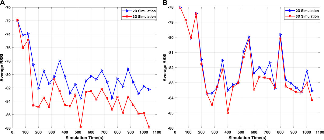
FIGURE 8. Average RSSI with respect to simulation time for two IoD deployment altitudes in the 2D and 3D propagation models. (A) 50-m deployment altitude, (B) 200-m deployment altitude.
To further evaluate the performance of the proposed 3D communication model, we study the impact of IoD deployment altitudes on IoD2V communication. The IoD nodes are deployed at different altitudes (30, 50, 100, 150, 200, 250, and 300-m), and the average RSSI and normalized coverage are presented in Figures 9A, B, respectively.
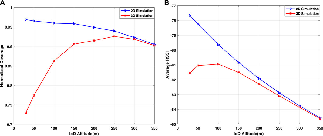
FIGURE 9. Average normalized coverage and RSSI for different IoD deployment altitudes. (A) Average normalized coverage, (B) Average RSSI.
Figures 9A, B show that the deployment altitude remarkably affects communication, where the VANET connectivity is enhanced as the altitude deployment increases. This trend increases with the deployment altitude, with the same transmission power up to 250-m, where the highest coverage is observed (optimal altitude deployment). This is because IoD nodes fly above high-level terrain, where the LoS condition toward the ground vehicles is improved. The coverage starts decreasing with increasing deployment altitude once the optimal altitude is achieved. Although increasing the IoD deployment altitude after the optimal value further improves the LoS condition and minimizes the impact of high-level terrain, it decreases the coverage and received signal quality; this is attributed to the increased distance between IoD nodes and ground vehicles, which in turn increases the path loss. Notably, the results show that the proposed approach finds the optimal deployment altitude of IoD nodes to achieve the best performance (coverage and RSSI). The optimal IoD deployment is obtained to maximize the coverage area and enhance the RSSI for such deployment. Thus, the RSSI at the optimal deployment might not represent the optimal RSSI value (Figure 9B). By contrast, in the 2D propagation model, the main factor affecting the propagated signal is the distance between the sender and receiver. Hence, the performance degrades as the altitude of IoD deployment increases owing to the increasing distance.
To further investigate the performance of the proposed 3D propagation model for IoD, we record the optimal locations of two deployed UAVs (IoD size) obtained by IPSO implementation during the simulation and connect them to create the optimal UAV paths generated by the 2D and proposed 3D propagation models. The altitude deployment is set in the range of 50–200-m. The results are shown in Figure 10A, where the trajectory of UAV in 2D and 3D space represents the optimal path to be followed to achieve the best coverage and received signal quality. The trajectories show that UAVs should be dynamically deployed to maximize the coverage and RSSI. The behavior of drones in 3D space evidently differs from that in 2D space, i.e., neglecting the terrain elevation. This is because the 3D propagation model considers the effect of terrain elevation on communication; thus, the drones are dispatched to the most appropriate locations for improving the LoS condition, thereby increasing increase the number of connected vehicles. The dynamic movement of UAVs allows the visualization of the altitude variation throughout the simulation, in which the coverage is maximized, and the received signal quality is improved in both models, as shown in Figure 10B, which presents UAV altitudes for both propagation models after removing the terrain information from the 3D simulation. The results show that the drone attempts to fly at a higher altitude in the 3D propagation model than that in the 2D propagation model. This occurs because, in the 3D propagation model, UAV altitude is constantly adjusted such that the signal quality toward ground vehicles is enhanced while avoiding NLoS conditions caused by terrain elevation between UAV and ground vehicles. The irregular terrain that acts as an obstacle enforces a UAV to fly at high altitudes to ensure good communication. Meanwhile, in the 2D model, the terrain elevation is neglected; therefore, the UAV flies at low altitudes for better performance.
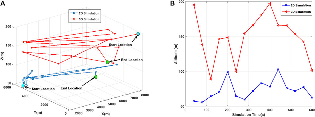
FIGURE 10. Trajectory of UAV and altitude variation in 2D and proposed 3D propagation models. (A) UAV trajectories, (B) Altitude variation.
5.3 Three-dimensional IoD-assisted VANET performance
In this subsection, we study the effect of IoD size and transmitted power on VANET connectivity and RSSI.
5.3.1 Effect of IoD size on VANET connectivity and RSSI
The average normalized coverage and RSSI are discussed for two altitude ranges. Further, different IoD sizes are implemented with 80-mW transmission power. The results are illustrated in Figure 11A for the altitude ranges of 50–100-m and 100–150-m.
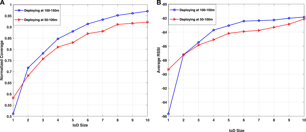
FIGURE 11. Average normalized coverage and RSSI for different IoD sizes in 3DIoDAV. (A) Average normalized coverage, (B) Average RSSI.
VANET connectivity is enhanced when integrated with IoD (Figure 11A). As the IoD size increases, this trend increases at the same power transmission, demonstrating the impact of IoD size on the coverage. However, increasing the IoD size might increase the interference and the probability of collision with other drones. Further, drones that are close to each other play the same role and become redundant. Therefore, drones must be separated at an adequate distance within their communication ranges, which is considered in this study.
When drones fly at low altitudes, the propagated signal is subjected to an NLoS condition due to the terrain elevation. Generally, IoD2V communication has been influenced by two main factors: LoS condition and path loss. Hence, deploying the IoD network at a low altitude decreases the distance between IoD and ground vehicles, which decreases the path loss and the probability of the LoS condition.
Deploying IoD nodes at high altitudes increases the probability of LoS conditions; however, this increases the distance between IoD nodes and ground vehicles, thereby increasing the path loss.
In the proposed 3D propagation model, wherein the terrain elevation is considered, deploying IoD at low altitudes might increase the path loss, and IoD2V communication might be hindered by terrain elevations. Consequently, several vehicles are isolated. This scenario is depicted in Figure 11A, where the average coverage is more enhanced in the altitude range of 100–150-m than that in the altitude range of 50–100-m. Moreover, the IoD size considerably influences the VANET connectivity and RSS. The coverage is improved as the IoD size increases, and the maximum coverage can be reached using ten drones for both altitude ranges.
To further evaluate the proposed 3DIoDAV, the impact of IoD size on RSSI is discussed. Particularly, the RSSI is measured with respect to simulation time, and the average RSSI with respect to IoD size is illustrated in Figure 11B. This figure reveals that the quality of the received signal is low at the beginning, when the target area is covered by only one UAV and increases as the number of UAVs increases. This is more advantageous in the altitude range of 100–150-m than that in the altitude range of 50–100-m because when UAVs fly at higher altitudes, the impact of terrain on IoD2V communication decreases, thereby improving the LoS condition.
5.3.2 Impact of transmission power on coverage and RSSI
To further investigate the effectiveness of the proposed 3DIoDAV, we discuss the impact of the power transmitted on the total coverage, i.e., the average normalized coverage. The results are depicted in Figures 12A, B for the altitude ranges of 50–100-m and 100–150-m, respectively.
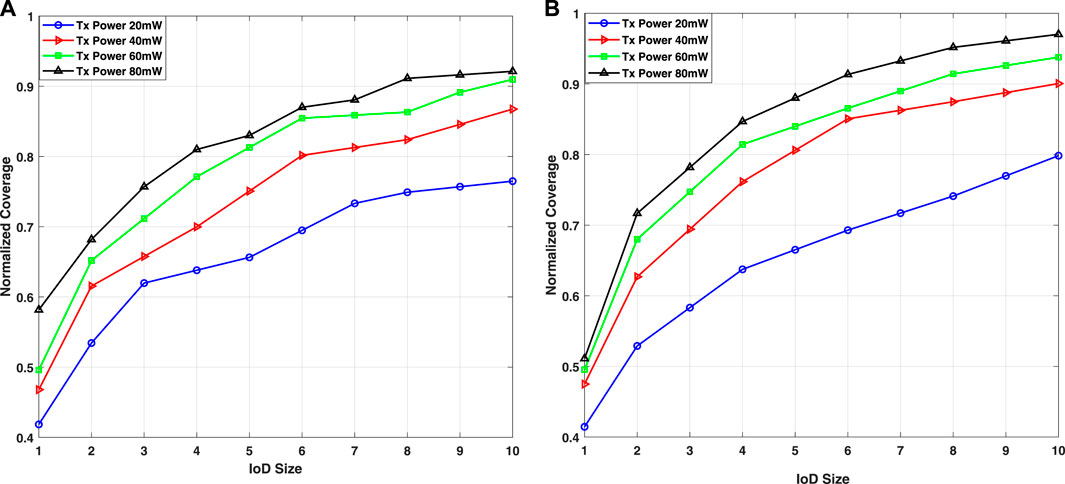
FIGURE 12. Average normalized coverage for different transmission powers with respect to various IoD sizes in 3DIoDAV. (A) 50–100 m deployment altitude, (B) 100–150 m deployment altitude.
Figure 12A depicts the normalized coverage with respect to the IoD size at different power transmissions (20, 40, 60, and 80-mW) for both altitude ranges. Thus, the effect of power transmission on the average normalized coverage is examined, where the latter rises continuously with the increase in power transmission, as expected. This intuitive proportional relationship is attributed to a higher power transmission indicating a wider coverage range and more covered vehicles, which improves the overall coverage. This tendency is evident in both altitude ranges, and the highest normalized coverage can be achieved in Scenario 1 (altitude range of 50–100-m) using 10 UAVs with power transmissions of 20, 40, 60, and 80-mW, achieving 76.4%, 86.2%, 92.0%, and 92.2% coverage, respectively, whereas the reached coverage in Scenario 2 (altitude range of 100–150-m) is 79.8%, 90%, 93.7%, and 99.1%, respectively. We observe that ten UAVs can cover 99.1% of isolated vehicles using 80-mW power transmission in Scenario 2, whereas the highest coverage achieved in Scenario 1 is 92%. Besides, transmission power considerably influences the received signal quality, where RSSI improves as the power of the transmitted signal increases for both altitude ranges (Figures 13A,B). In summary, the power transmission greatly improves the VANET performance.
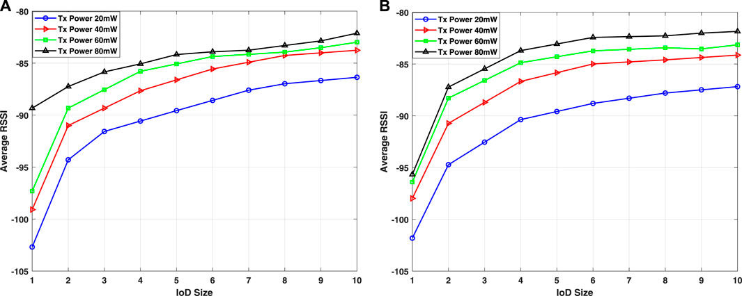
FIGURE 13. Average RSSI for different transmission power values with respect to different IoD sizes in 3DIoDAV. (A) 50–100 m deployment altitude, (B) 100–150 m deployment altitude.
5.4 Comparison with other approaches
To validate the proposed 3DIoDAV, we compare our proposed 3DIoDAV with a 2D propagation model and IoDAV Ahmed G. A. et al. (2021). We consider the average normalized coverage and RSSI as performance metrics. The comparison includes average normalized coverage and RSSI with respect to IoD size for 80-mW transmission power. We further demonstrate the effect of the transmission power on the coverage for ten drones in the comparison.
Figures 14A, B compare the normalized coverage using 3DIoDAV, 2D, and IoDAV approaches for both altitude ranges. Average RSSI values are shown in Figures 15A, B for Scenarios 1 and 2, respectively. These figures indicate that the IoD size considerably influences the performance as the average normalized coverage increases with IoD size. The results reveal that the proposed 3DIoDAV approach yields lower coverage and RSSI than other approaches. This is because the proposed 3DIoDAV approach considers the impact of terrain elevation on communication, which was previously neglected. Thus, it reflects a more realistic result. The coverage and RSSI are improved as the altitude increases for the proposed 3DIoDAV approach. This is clearly observed in Scenario 2because when a drone flies at high altitudes, the LoS condition is improved, thereby improving the communication between IoD and ground vehicles. To summarize the observations highlighted in Figures 15A, B, we plot the average normalized coverage and RSSI as functions of the power transmission for ten IoD sizes in Figures 16A, B for both scenarios.
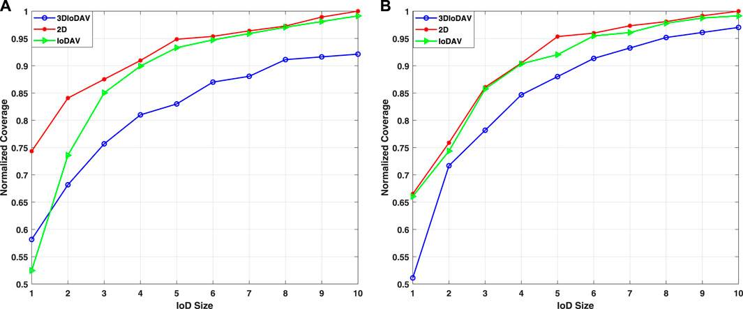
FIGURE 14. Average normalized coverage for different IoD sizes in 3DIoDAV, 2D, and IoDAV approaches. (A) 50–100 m deployment altitude, (B) 100–150 m deployment altitude.
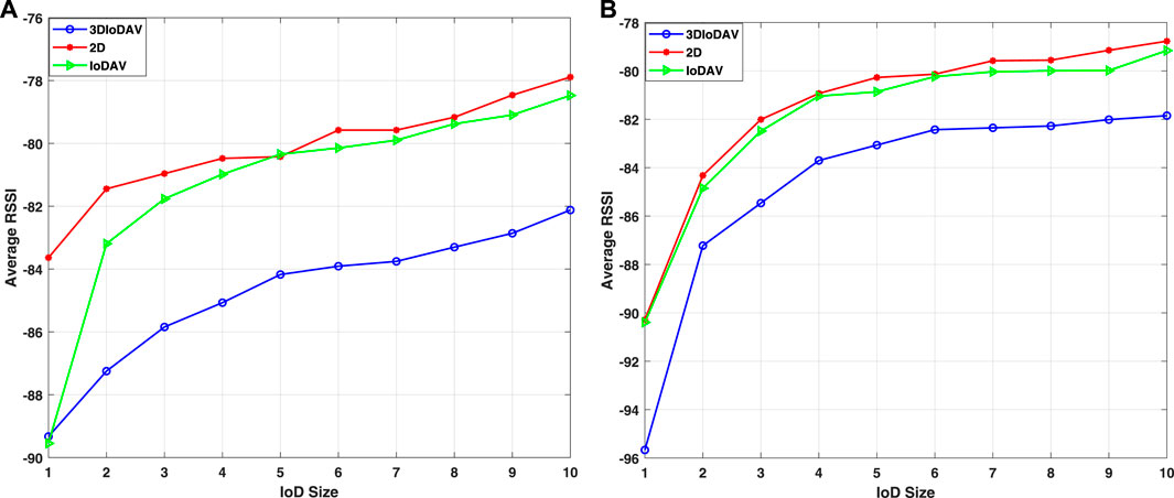
FIGURE 15. Average RSSI for different sets of UAVs in the three approaches. (A) 50–100 m deployment altitude, (B) 100–150 m deployment altitude.
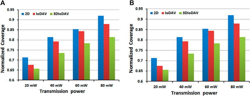
FIGURE 16. Average normalized coverage in the three approaches for different transmission power values for 10 UAVs. (A) 50–100 m deployment altitude, (B) 100–150 m deployment altitude.
Although the 2D and IoDAV approaches achieve better coverage and better RSSI values than our approach, they do not reflect real results as the impact of terrain elevation on communication is neglected. The lower coverage and RSSI shown by our approach in Figures 16A, B demonstrate the impact of terrain elevation on signal propagation, which is considerable must not be neglected. The results also demonstrate the ability of the proposed 3DIoDAV to detect the terrain obstacles and dispatch IoD nodes to optimal locations that minimize the effect of terrain elevation on communication.
Finally, to demonstrate the ability of the proposed approach to dispatch the IoD nodes to the most appropriate locations, we run the 2D simulation model to obtain its predicted optimal locations and then evaluate the 2D deployment using the 3DIoDAV approach. The results are compared with optimal locations obtained by the 3DIoDAV approach (3D deployment).
The results are illustrated in Figures 17A, B for normalized coverage and RSSI, respectively. The locations obtained by the proposed 3DIoDAV approach provide higher coverage and better RSSI than those obtained by the 2D propagation model, demonstrating the ability of the proposed 3DIoDAV to dispatch IoD nodes to the most appropriate locations that improve VANET performance.
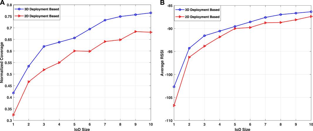
FIGURE 17. 2D and 3D IoD deployment evaluated by 3DIoDAV for different sets of UAVs: (A) Average normalized coverage and (B) average RSSI.
6 Conclusion
In this study, we developed a novel 3D propagation model for IoD2V communication that considers the terrain elevation information for the communication between IoD in the air and vehicles on the ground. The proposed 3D propagation model was evaluated via simulation and compared with a 2D propagation model. The results show a remarkable impact of terrain information on communication. Particularly, our proposed IoD2V propagation model detects the terrain obstacles and properly evaluates the received signal quality. We employed the proposed 3D propagation model in the IoDAV approach to develop a novel 3DIoDAV approach in which the IoD network improves the VANET connectivity. We further proposed the use of an optimization approach, IPSO, to optimally deploy the IoD network to maximize the coverage area and enhance the quality of the received signal. Notably, the proposed 3DIoDAV was compared with 2D and IoDAV approaches, illustrating the capability of the proposed 3DIoDAV approach to retrieve the terrain information and consider it in the communication between IoD and ground vehicles, thereby providing realistic prediction results.
The proposed model will be extended in a future study by considering buildings as obstacles, and the resulting signal attenuation will be investigated. However, designing such simulation model will poses a challenge in creating an environment that precisely captures the dynamics of IoDs and vehicles. To address this, future efforts can concentrate on enhancing the simulation environment through the inclusion of realistic scenarios like urban and highway settings, diverse traffic conditions, and varied communication scenarios.
Data availability statement
The raw data supporting the conclusion of this article will be made available by the authors, without undue reservation.
Author contributions
GA: Conceptualization, Investigation, Methodology, Software, Validation, Writing–original draft, Visualization. TS: Conceptualization, Funding acquisition, Investigation, Project administration, Supervision, Validation, Writing–original draft, Resources. AM: Conceptualization, Investigation, Validation, Writing–review and editing. AY: Methodology, Validation, Conceptualization, Writing–review and editing.
Funding
The authors declare financial support was received for the research, authorship, and/or publication of this article. This work was supported by (the interdisciplinary center of smart mobility and logistics at King Fahd University of Petroleum and Minerals) [Grant number (INML2033)]. This study was also supported by the Special Research Fund (BOF) number BOF23KV17.
Acknowledgments
The authors acknowledge the support project number INML2104 under the interdisciplinary center of smart mobility and logistics and the computer engineering department at King Fahd University of Petroleum and Minerals for this study.
Conflict of interest
The authors declare that the research was conducted in the absence of any commercial or financial relationships that could be construed as a potential conflict of interest.
Publisher’s note
All claims expressed in this article are solely those of the authors and do not necessarily represent those of their affiliated organizations, or those of the publisher, the editors and the reviewers. Any product that may be evaluated in this article, or claim that may be made by its manufacturer, is not guaranteed or endorsed by the publisher.
References
Ahmed, G., Sheltami, T., Deriche, M., and Yasar, A. (2021a). An energy efficient iod static and dynamic collision avoidance approach based on gradient optimization. Ad Hoc Netw. 118, 102519. doi:10.1016/j.adhoc.2021.102519
Ahmed, G., Sheltami, T., Mahmoud, A., and Yasar, A. (2020). Iod swarms collision avoidance via improved particle swarm optimization. Transp. Res. Part A Policy Pract. 142, 260–278. doi:10.1016/j.tra.2020.09.005
Ahmed, G. A., Sheltami, T. R., Mahmoud, A. S., Imran, M., and Shoaib, M. (2021b). A novel collaborative iod-assisted vanet approach for coverage area maximization. IEEE Access 9, 61211–61223. doi:10.1109/access.2021.3072431
Andreou, A., Mavromoustakis, C. X., Batalla, J. M., Markakis, E. K., and Mastorakis, G. (2023). UAV-assisted RSUs for V2X connectivity using voronoi diagrams in 6G + infrastructures. IEEE Trans. Intell. Transp. Syst., 1–11. doi:10.1109/TITS.2023.3273716
Azzoug, Y., and Boukra, A. (2022). Enhanced uav-aided vehicular delay tolerant network (vdtn) routing for urban environment using a bio-inspired approach. Elsevier.102902
Drusch, M., Del Bello, U., Carlier, S., Colin, O., Fernandez, V., Gascon, F., et al. (2012). Sentinel-2: esa’s optical high-resolution mission for gmes operational services. Remote Sens. Environ. 120, 25–36. doi:10.1016/j.rse.2011.11.026
Gupta, M., and Varma, S. (2021). Optimal placement of uavs of an aerial mesh network in an emergency situation. J. Ambient Intell. Humaniz. Comput. 12, 343–358. doi:10.1007/s12652-020-01976-2
Hadiwardoyo, S. A., Calafate, C. T., Cano, J.-C., Ji, Y., Hernández-Orallo, E., and Manzoni, P. (2018). 3d simulation modeling of uav-to-car communications. Ieee Access 7, 8808–8823. doi:10.1109/access.2018.2889604
Hadiwardoyo, S. A., Calafate, C. T., Cano, J.-C., Krinkin, K., Klionskiy, D., Hernández-Orallo, E., et al. (2019). “Optimizing uav-to-car communications in 3d environments through dynamic uav positioning,” in 2019 IEEE/ACM 23rd international symposium on distributed simulation and real time applications (DS-RT) (IEEE), 1–8.
Haklay, M., and Weber, P. (2008). Openstreetmap: user-generated street maps. IEEE Pervasive Comput. 7, 12–18. doi:10.1109/mprv.2008.80
He, X., Yu, W., Xu, H., Lin, J., Yang, X., Lu, C., et al. (2018). “Towards 3d deployment of uav base stations in uneven terrain,” in Proc. IEEE 27th int. Conf. Comput. Commun. Netw (Hangzhou, China: ICCCN), 1–9.
Islam, M. M., Khan, M. T. R., Saad, M. M., Tariq, M. A., and Kim, D. (2022). Dynamic positioning of uavs to improve network coverage in vanets. Veh. Commun. 36, 100498. doi:10.1016/j.vehcom.2022.100498
Jiang, B., Yang, J., Xu, H., Song, H., and Zheng, G. (2018). Multimedia data throughput maximization in internet-of-things system based on optimization of cache-enabled uav. IEEE Internet Things J. 6, 3525–3532. doi:10.1109/jiot.2018.2886964
Khoshafa, M. H., Ngatched, T. M., and Ahmed, M. H. (2020). On the physical layer security of underlay relay-aided device-to-device communications. IEEE Trans. Veh. Technol. 69, 7609–7621. doi:10.1109/tvt.2020.2994505
Kim, H., Ben-Othman, J., Hwang, K., and Choi, B. (2022). Intelligent aerial-ground surveillance and epidemic prevention with discriminative public and private services. IEEE Netw. 36 (3), 40–46.
Krajzewicz, D., Erdmann, J., Behrisch, M., and Bieker, L. (2012). Recent development and applications of sumo-simulation of urban mobility. Int. J. Adv. Syst. Meas. 5, 128–138.
Lee, S., Lee, S., Choi, Y., Ben-Othman, J., Mokdad, L., and Kim, H. (2023). Time varied self-reliance aerial ground traffic monitoring system with pre-recognition collision avoidance. IEEE Commun. Lett. 27 (5), 1477–1480. doi:10.1109/LCOMM.2023.3258922
Lee, W. C. (1998). Mobile communications engineering: theory and applications. McGraw-Hill Education.
Lin, N., Fu, L., Zhao, L., Min, G., Al-Dubai, A., and Gacanin, H. (2020). A novel multimodal collaborative drone-assisted vanet networking model. IEEE Trans. Wirel. Commun. 19, 4919–4933. doi:10.1109/twc.2020.2988363
Lin, X., Yajnanarayana, V., Muruganathan, S. D., Gao, S., Asplund, H., Maattanen, H.-L., et al. (2018). The sky is not the limit: lte for unmanned aerial vehicles. IEEE Commun. Mag. 56, 204–210. doi:10.1109/mcom.2018.1700643
Manzoor, A., Dang, T. N., and Hong, C. S. (2021). “Uav trajectory design for uav-2-gv communication in vanets,” in 2021 international conference on information networking (ICOIN) (IEEE), 219–224.
Mokhtari, S., Nouri, N., Abouei, J., Avokh, A., and Plataniotis, K. N. (2022). Relaying data with joint optimization of energy and delay in cluster-based uav-assisted vanets. IEEE Internet Things J. 9, 24541–24559. doi:10.1109/jiot.2022.3188563
Mozaffari, M., Saad, W., Bennis, M., and Debbah, M. (2016). Efficient deployment of multiple unmanned aerial vehicles for optimal wireless coverage. IEEE Commun. Lett. 20, 1647–1650. doi:10.1109/lcomm.2016.2578312
Oubbati, O. S., Chaib, N., Lakas, A., Lorenz, P., and Rachedi, A. (2019). Uav-assisted supporting services connectivity in urban vanets. IEEE Trans. Veh. Technol. 68, 3944–3951. doi:10.1109/TVT.2019.2898477
Oubbati, O. S., Lakas, A., Lorenz, P., Atiquzzaman, M., and Jamalipour, A. (2019). Leveraging communicating uavs for emergency vehicle guidance in urban areas. IEEE Trans. Emerg. Top. Comput. 7, 1.
Oubbati, O. S., Lakas, A., Zhou, F., Güneş, M., Lagraa, N., and Yagoubi, M. B. (2017). Intelligent uav-assisted routing protocol for urban vanets. Comput. Commun. 107, 93–111. doi:10.1016/j.comcom.2017.04.001
Raja, G., Anbalagan, S., Subramaniyan, A. G., Selvakumar, M. S., Bashir, A. K., and Mumtaz, S. (2021). Efficient and secured swarm pattern multi-uav communication. IEEE Trans. Veh. Technol. 70, 7050–7058. doi:10.1109/tvt.2021.3082308
Raza, A., Bukhari, S. H. R., Aadil, F., and Iqbal, Z. (2021). An uav-assisted vanet architecture for intelligent transportation system in smart cities. Int. J. Distributed Sens. Netw. 17, 155014772110317. doi:10.1177/15501477211031750
Sabino, S., and Grilo, A. (2018). “Topology control of unmanned aerial vehicle (uav) mesh networks: a multi-objective evolutionary algorithm approach,” in Proc. 4th ACM workshop micro aerial veh. Netw., syst. (New York, NY, USA, 45–50.
Sami, H., Saado, R., Saoudi, A. E., Mourad, A., Otrok, H., and Bentahar, J. (2023). Opportunistic UAV deployment for intelligent on-demand IoV service management. IEEE Trans. Netw. Serv. Manag. 20 (3), 3428–3442. doi:10.1109/TNSM.2023.3242205
Seliem, H., Shahidi, R., Ahmed, M. H., and Shehata, M. S. (2018). Drone-based highway-vanet and das service. IEEE Access 6, 20125–20137. doi:10.1109/access.2018.2824839
Sommer, C., Eckhoff, D., German, R., and Dressler, F. (2011). “A computationally inexpensive empirical model of ieee 802.11 p radio shadowing in urban environments,” in Proc. IEEE 8th int. Conf. Wireless on-demand netw. Syst. Services (IEEE), 84–90.
Sommer, C., German, R., and Dressler, F. (2010). Bidirectionally coupled network and road traffic simulation for improved ivc analysis. IEEE Trans. Mob. Comput. 10, 3–15. doi:10.1109/tmc.2010.133
Su, Y., Liwang, M., Chen, Z., and Du, X. (2023). Toward optimal deployment of uav relays in uav-assisted iov networks. IEEE Trans. Veh. Technol. 72 (10), 13392–13405. doi:10.1109/TVT.2023.3272648
Tuba, E., Capor-Hrosik, R., Alihodzic, A., and Tuba, M. (2017). Drone placement for optimal coverage by brain storm optimization algorithm. In Proc. Int. Conf. Health inf. Sci. Cham, Switzerland: Springer, 167–176.
Varga, A., and Hornig, R. (2008). “An overview of the omnet++ simulation environment,” in Proc. 1st int. Conf. Simulation tools techn. Commun. (Marseille, France: Netw. Syst. workshops), 60.
Waleed, S., Ullah, I., Khan, W. U., Rehman, A. U., Rahman, T., and Li, S. (2021). Resource allocation of 5g network by exploiting particle swarm optimization. Iran J. Comput. Sci. 4, 211–219. doi:10.1007/s42044-021-00091-5
Wang, X., Fu, L., Zhang, Y., Gan, X., and Wang, X. (2016). Vdnet: an infrastructure-less uav-assisted sparse vanet system with vehicle location prediction. Wirel. Commun. Mob. Comput. 16, 2991–3003. doi:10.1002/wcm.2727
Xu, L., Zhou, X., Khan, M. A., Li, X., Menon, V. G., and Yu, X. (2021). Communication quality prediction for internet of vehicle (iov) networks: an elman approach. IEEE Trans. Intelligent Transp. Syst. 23, 19644–19654. doi:10.1109/tits.2021.3088862
Yang, G.-W., and Zhang, S. (2021). A dual-band shared-aperture antenna with wide-angle scanning capability for mobile system applications. IEEE Trans. Veh. Technol. 70, 4088–4097. doi:10.1109/tvt.2021.3072556
Yang, Q., and Yoo, S.-J. (2018). Optimal uav path planning: sensing data acquisition over iot sensor networks using multi-objective bio-inspired algorithms. IEEE Access 6, 13671–13684. doi:10.1109/access.2018.2812896
Keywords: IoD, DEM, altitude deployment, 3DIODAV, IPSO, VANET
Citation: Ahmed G, Sheltami T, Mahmoud A and Yasar A (2023) 3D simulation model for IoD-to-vehicles communication in IoD-assisted VANET. Front. Built Environ. 9:1287373. doi: 10.3389/fbuil.2023.1287373
Received: 01 September 2023; Accepted: 06 November 2023;
Published: 27 November 2023.
Edited by:
Hakim Ghazzai, King Abdullah University of Science and Technology, Saudi ArabiaReviewed by:
Hyunbum Kim, Incheon National University, Republic of KoreaMauro Tropea, University of Calabria, Italy
Copyright © 2023 Ahmed, Sheltami, Mahmoud and Yasar. This is an open-access article distributed under the terms of the Creative Commons Attribution License (CC BY). The use, distribution or reproduction in other forums is permitted, provided the original author(s) and the copyright owner(s) are credited and that the original publication in this journal is cited, in accordance with accepted academic practice. No use, distribution or reproduction is permitted which does not comply with these terms.
*Correspondence: Tarek Sheltami, dGFyZWtAa2Z1cG0uZWR1LnNh