
95% of researchers rate our articles as excellent or good
Learn more about the work of our research integrity team to safeguard the quality of each article we publish.
Find out more
ORIGINAL RESEARCH article
Front. Built Environ. , 17 October 2023
Sec. Construction Materials
Volume 9 - 2023 | https://doi.org/10.3389/fbuil.2023.1286933
This article is part of the Research Topic Additive Manufacturing in Construction View all 6 articles
 David Briels1*
 Mauritz Renz1
 Ahmad Saleem Nouman1
 Alexander Straßer2Maximilian Hechtl2Maximilian Dahlenburg3Bruno Knychalla4Patrick Sonnleitner4Friedrich Herding5
 Julia Fleckenstein6
 Ema Krakovská6Kathrin Dörfler6Thomas Auer1
Additive Manufacturing (AM) offers transformative opportunities to create functionally hybridized, insulating, monolithic AM wall elements. The novel fabrication methods of AM allow for the production of highly differentiated building components with intricate internal and external geometries, aiming for reduced material use while integrating and enhancing building performance features including thermal insulation performance. This study focuses on integrating such thermal insulation performance by leveraging the individual features of three distinct AM processes: Selective Paste Intrusion (SPI), Selective Cement Activation (SCA), and Extrusion 3D Concrete Printing (E3DCP). Using a simulation-based parametric design approach, this research investigates 4,500 variations of monolithic AM façade elements derived from a generative hexagonal cell layout with differing wall widths, the three respective AM processes, different material compositions with and without lightweight aggregates, and three different insulation strategies, namely, air-filled cells, encapsulated lightweight aggregates, and additional insulation material within the cavities. Thermal performance feedback is realized via 2D heat flux simulations embedded into a parametric design workflow, and structural performance is considered in a simplified way via geometric and material-specific evaluation. The overall research goal is a multi-objective design optimization, particularly identifying façade configurations that achieve a U-value of less than 0.28 W/m2K and a theoretical compressive strength exceeding 2.70 MN per meter wall length. The results of this study detect 7% of all generated variations in line with these thermal and structural requirements, validating the feasibility of monolithic, thermally insulating AM wall elements. The presented workflow contributes to exploiting the potential of a new design of functionally hybridized AM components.
As the barrier between the indoor and outdoor environment, the building envelope is primarily responsible for managing various building physics requirements, including influences from categories such as heat, moisture, airtightness, sound, and light (Knaack and Koenders, 2018). In general there are three different principle façade systems to solve these requirements: massive constructions, integrating all requirements; layered constructions, with individual layers for individual requirements; and skeleton or frame constructions, separating the loadbearing function from the space-enclosing function (Knaack and Koenders, 2018, p. 122). Massive or monolithic constructions consisting, for example, of hollow bricks or lightweight concrete, provide a simple solution for satisfying all requirements in one element. However, optimizing individual functionalities or adaptability of such massive constructions are limited. Alternatively, multilayered façades, such as rear-ventilated facades, allow for the functional optimization of separate layers. But on the downside, they result in a complex and, thus, error-prone composite system with low recyclability, which is especially the case for external thermal insulation composite systems. Therefore, there is an aspiration to integrate, hybridize and optimize building functions in construction elements without these drawbacks. In this context, Additive Manufacturing (AM) has significant potential.
AM has emerged as a promising new paradigm for the construction industry (Paolini et al., 2019; Pessoa et al., 2021; Bos et al., 2022). Due to its novel fabrication method, by additively creating free-form geometries layer upon layer, AM allows for meeting customizable needs and thereby unfolds new possibilities for designing building elements. Lim et al. (2020) for instance demonstrated the manufacturing of saddle and dome-shaped concrete surfaces. Furthermore, AM offers the promising potential of fabricating monolithic elements characterized by intricate internal and external geometries, enabling the integration, individualization, hybridization, and optimization of performative features of building components (Dielemans et al., 2021; Briels et al., 2022; Piccioni et al., 2023). This innovative design approach offers high potential, especially for façade elements, one of the most complex building elements (Leschok et al., 2023). The inherent intricacy achievable through AM negates the need for diverse layers and materials. This, in turn, fosters recyclability and notably reduces work steps and interdependence between various construction disciplines on site (Schutter et al., 2018). The cascading effect of these advantages culminates in a building process that is streamlined and productive.
The building envelope plays a critical role in maintaining the indoor environmental quality (IEQ) of a building, most notably via thermal regulation. The transmission heat losses are primarily responsible for the heating energy demand of buildings, to which the façade contributes around 20% (Lima et al., 2021; Pessoa et al., 2021). Consequently, enhancing the thermal performance of the building envelope can result in substantial energy savings and reductions in the related operational carbon emissions, obviously also concomitant with suitable approaches for building technology (Hepf et al., 2023). An overarching aim of this research is a reduction of embodied and operational carbon emissions inherent to the building process and the operation of buildings. The embodied carbon footprint can be lowered by rationalizing material use and cutting cement content. In parallel, operational carbon emissions are primarily caused by heating and cooling energy consumption. It is aspirational to significantly reduce heat transfer losses by improving the thermal efficiency of building envelopes, thereby decreasing operational carbon emissions.
There are various legal requirements to ensure adequate thermal insulation quality of building envelopes. With its Energy Saving Ordinance (GEG), Germany mandates at least a U-value of 0.28 W/m2K for exterior walls of new buildings and 0.24 W/m2K for energetic modernization of the façade (GEG, 2020). Analogous standards are entrenched in regulations across the European Union and the United States, namely, in the United Kingdom, ranging from 0.18 W/m2K (new building) to 0.30 W/m2K (renovation) (RIBA, 2021), in France, according to RE 2020 a U-value of 0.34–0.45 W/m2K is specified (Deslot et al., 2020), and in the US the value ranges from 0.26–1.12 W/m2K depending on climate zones (ICC, 2021), which in the US indicates diverse requirements due to climatic conditions. However, this underlines the ubiquitous demand and inherent necessity for thermal efficiency of façade elements.
With its distinct features, AM offers potential advancements in thermal insulation for building components, as shown in a recent literature review by Pessoa et al. (2021). Synoptically, there are three main approaches to achieving thermal insulation with AM:
• Biomimetic design with cellular or lattice structures
• Reducing the thermal conductivity of the AM material composition
• Adding insulation material into voids or in between AM elements
Lopes et al. (2023) and Piccioni et al. (2023) have evaluated in their studies infill patterns for Fused Deposition Modeling (FDM) with plastic feed material, targeting façade elements. Furthermore, research has explored various internal patterns focusing on E3DCP (Dielemans et al., 2021; Marais et al., 2021; Suntharalingam et al., 2021; Briels et al., 2022; Cuevas et al., 2023) but also considered different infills, ranging from stationary air and foam concrete to additionally inserted insulating materials. At the same time, some research primarily focuses on reducing the thermal conductivity of the material composition used for various AM processes (Weger et al., 2020; Strzałkowski et al., 2021; Hechtl et al., 2023; Strasser et al., 2024). Despite the burgeoning interest in AM, empirical studies on the thermal performance of AM elements still need to be more extensive, and especially the design and assessment of monolithic AM facade elements’ thermal characteristics need to be more holistic. Here, the current body of research exhibits a noticeable void regarding the comparative analysis of different AM processes, materials, and respective strategies to improve the thermal insulation performance of monolithic AM façade elements. Marais et al. (2021) underline in their research also the importance of these dependencies when trying to improve thermal performance. Contributing to close this gap, this research aims to answer the following questions:
• What are different strategies to improve the thermal insulation of monolithic AM wall elements, and can their efficacy be verified?
• Which parameters influence the thermal insulation of AM wall elements with an internal cell structure, and what are measurable correlations?
• What are the resulting parameters to achieve a U-value of at least 0.28 W/m2K while maintaining a reasonable theoretical compressive strength of at least 2.7 MN/m?
• What combinations of AM processes, materials, and insulation strategies provide good synergy between thermal insulation and compressive strength?
To answer these questions, this research undertakes in Section 2.1 a comprehensive review of three distinct AM processes, namely, Selective Cement Activation (SCA), Selective Paste Intrusion (SPI), and Extrusion 3D Concrete Printing (E3DCP), focusing on their inherent process characteristics, material properties, and fabrication constraints. The thermal conductivity and compressive strength are experimentally evaluated for all three processes. The feasibility is ensured via test prints and large-scale demonstrator objects (see Figure 1). Section 2.2 covers the topic of thermally enhancing AM wall elements. After introducing the basics of heat transfer in cellular solids, four general approaches are described in detail for improving the thermal insulation of AM elements: a) adding lightweight aggregates in the material composition, b) encapsulating air in a cellular structure, c) encapsulating unbound lightweight aggregates in cavities, and d) adding loose-fit insulation material into the structures’ voids. After this theoretical background, a simulation-based parametric design workflow is introduced in Section 2.3, enabling parametric studies and paving the way for a design tool with performance feedback for thermal insulation. Besides the software workflow, the generative geometry modeling and individual characteristics of the used 2D heat flux simulations are described, calculating the heat transport through horizontal sections. Furthermore, the specifications for a thorough parametric study are defined, and a simplified estimation of a theoretical compressive strength is included in order to classify the results in the context of their structural properties. The results of this comparative study are presented in Section 3, and on that basis the research questions are recapitulated and answered in Section 4, followed by a final conclusion and outlook in Section 5.
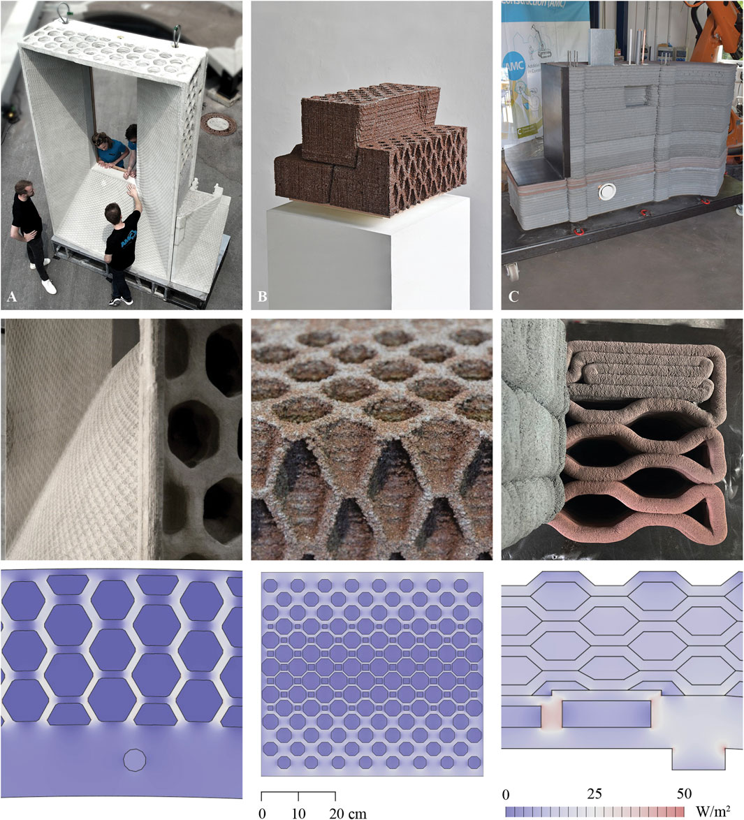
FIGURE 1. Top: Three realized demonstrator objects: (A) “Breuer X AM” (SCA), (B) “Playing with Blocks” (SPI), and (C) “Marriage of two Materials” (E3DCP). Top: full view of demonstrator objects. Middle: close-up of cell structure. Reprinted with permission from Dörfler et al. (2023). Bottom: Corresponding results of 2D heat flux simulations, visualizing the heat flux density in horizontal sections.
In the following sections, three different AM processes are introduced, covering two particle-bed processes, namely, Selective Cement Activation (SCA), and Selective Paste Intrusion (SPI), and one extrusion-based process, Extrusion 3D Concrete Printing (E3DCP) is represented. These processes are further divided into a total of six different material compositions, and in Table 1, the respective material characteristics thermal conductivity, compressive strength, and density) are listed. For SCA, one material composition is chosen without lightweight aggregates (LWA), and one with Lightweight Expanded Glass Aggregates (LEGA). Lightweight Expanded Clay Aggregates (LECA) are used for SPI. Table 1 shows the associated material characteristics for the material bound with cement paste and the unbound material. For E3DCP, two material mixtures were chosen, one Natural Sand Mortar (NSM) and one Lightweight Mortar (LWM), again with LEGA.
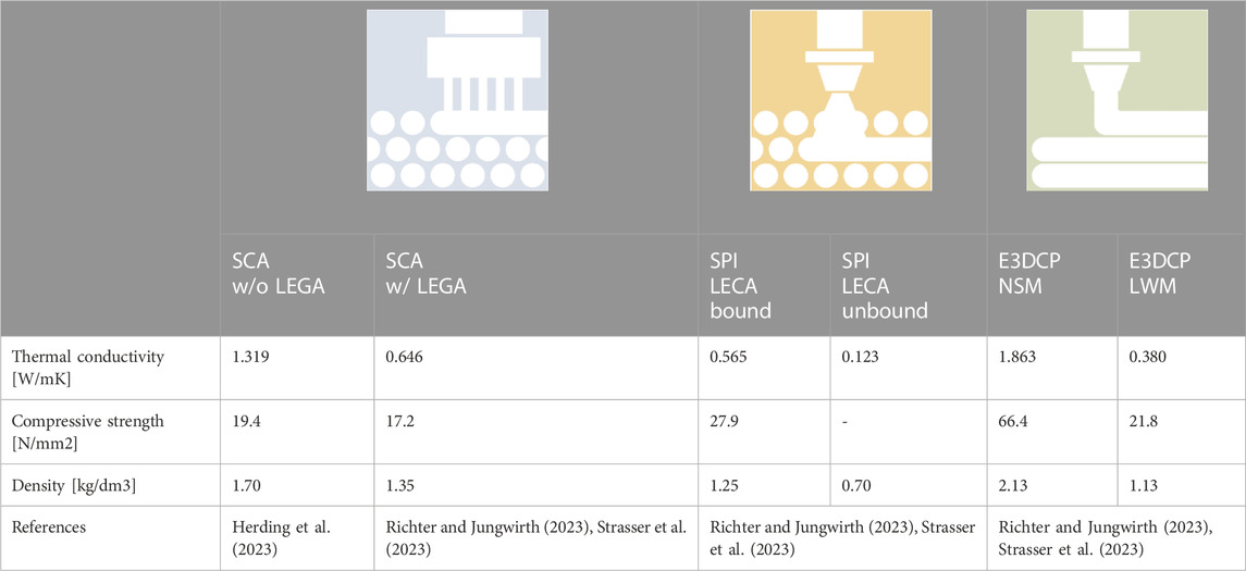
TABLE 1. Relevant physical properties of the investigated AM process and material combinations.
Selective binding pertains to a series of powder bed processes known as Particle Bed 3D Printing (PB3DP). In this context, an initial layer of loose, non-self-hardening powder or particle material of a defined thickness is applied within a printing area, also called the build space. In the second step, a hardening agent or activator is locally applied to solidify the previously laid powder or particle layer. A three-dimensional object is formed by repetitively performing these two operations while concurrently adjusting the height of the build space or the powder bed.
In Selective Activation, an activator in a liquid state is applied to a powder bed, typically consisting of fine grains (<1 mm), and adding lightweight aggregates is also possible. This activator triggers the hardening reaction of the binder present in the powder bed. Water is utilized as the activator when binding cement, whereas a magnesium chloride solution is used when binding magnesium oxide. Given its low viscosity, the activator can be applied using a print head equipped with multiple individual nozzles spanning the entire width of the build space (approximately one nozzle/mm).
This research focuses on two types of material compositions, whereas both fall in the category of cement-based SCA material. One of the two materials is a lightweight SCA material with added LEGA. The other one is a traditional mixture without lightweight aggregates (LWA).
The material SCA w/LEGA consists of 70 M-% Portland cement, 29 M-% LEGA, and 1 M-% cellulose ether. The fine grain size accounts for 0–0.5 mm for the powder bed, compacted by 15%, resulting in a layer thickness of 1.5 s of 1.5 mm. This material composition, with a w/c (water to cement) ratio of 0.3, results after 42 days of curing in compressive strength of 17.2 N/mm2, measured parallel to the layer orientation on cubical specimens with 100 mm, and a density of 1.35 kg/dm3. Due to the fabrication process, the material shows anisotropic mechanical and thermal properties, depending on the layer orientation. Shakor et al. (2021) also found orthotropic properties in their experimental and numerical analysis. For instance, the compressive strength measured perpendicular to the layers is significantly lower at 11.3 N/mm2 (Richter and Jungwirth, 2023).
The thermal conductivity was determined on nine post-processed (cut, ground, dried) prisms with 40 × 40 × 160 mm after 28 days. A Hot Disk TPS1500 with a 6.4 mm sensor (Kapton 5501) was used for the measurements according to the hot disc method described in ISO 22007-2:2015-12. There are 3 test prisms each for all three layer orientations. The evaluated thermal conductivity ranges from 0.603 (y) and 0.647 (x) to 0.686 W/mK (z). The overall mean value thus accounts for 0.646 W/mK, with a total standard deviation of 0.0475 (Strasser et al., 2023).
Comparing these values to other SCA material mixtures with LWA found in the literature, Weger et al. (2020) achieved a significantly lower thermal conductivity of up to 0.22 W/mK but with a compressive strength of less than 4.0 N/mm2.
The second material composition is a mixture without LWA, similar to the ones outlined by Mai et al. (2022). It consists of fine aggregates (quartz sand), a rapid-setting cement (Portland cement with Mayenite), and methyl cellulose granules (<1 M-%) (Mai et al., 2022). The volumetric ratio of aggregates to cement was set to 60/40, and again, water was used as an activator with a w/c ratio of 0.4 and a resulting layer height of 1 mm. The compressive strength accounts for 19.4 N/mm2 at a 1.70 kg/dm3 density. As described before, the thermal conductivity was experimentally evaluated, resulting in a mean value of 1.319 W/mK (Herding et al., 2023).
Due to the low layer height of around 1.5 mm, the fine grain size of less than 1 mm, and the numerous small nozzles (approximately one nozzle per mm), SCA enables high precision and resolution, both on the surface and for intricate infill patterns, particularly for very complex internal structures with, for example, overhangs and free-form geometries, a significant advantage of SCA, in addition to its high resolution, is the fact that the powder bed itself acts as a support structure.
One limiting factor is the requirement to remove the inactivated powder bed. Although the powder may have some insulating properties, the cement content makes it inappropriate to leave the inactivated material in cavities, as this would compromise the overall objective of reducing embodied carbon emissions. Consequently, only open-cell structures are considered practical for SCA. Additionally, an appropriate size of the cavities of such open-cell structures is essential to allow for inserting a suction hose into the holes for removing the inactivated material. Furthermore, the adhesion of material at the interface between activated and inactivated powder is challenging for this process step.
In general, this AM process is very suitable for prefabrication due to its large machinery setup. However, manufacturing large, monolithic SCA elements is still a significant challenge for the process, mainly due to the material shrinkage and the potential of cracking, as well as due to process handling steps including the unpacking of the printed elements from the powder bed and subsequent transportation. The combination of massive and thin structures could adversely affect this topic.
Architect Marcel Breuer developed in his project “IBM Research Center in La Gaude, France, 1960-1962,” a pioneering modular building envelope system made of precast concrete elements, in which he combined building services, installation, and passive solar protection measures within one multifunctional façade panel. Due to the concrete casting manufacturing methods and the resulting standardized series production, a local differentiation of the internal and external structure to respond to varying physical conditions for the building was not realizable. AMC offers a remarkable opportunity to integrate those complex functional requirements with streamlined manufacturing processes with a high degree of design freedom. Within this context, the large-scale demonstrator “Breuer X AM” expands Breuer’s architectural concept to integrate performance-based and locally customized design approaches supported by AM technology using SCA to realize a bespoke building envelope element at full building scale (3.00 m × 1.80 m x 0.75 m in height, width and depth) illustrated in Figure 1 (Dörfler et al., 2023; Fleckenstein et al., 2023). The demonstrator is designed and planned as a functional hybrid to validate the general applicability of computational design approaches based on solar radiation simulations for form-based changes, the functional integration of thermal aspects, and the integration of load-bearing requirements at the component level. The thermal zone design, with approximately 50 cm at the widest point, consists of a hexagonal, graded cellular structure open on all four sides, filled with insulation material after on-site assembly. The graded cell size of approximately 80–100 mm enabled an easy removal of unbound material, while the graded cell rib thickness of roughly 20–40 mm addresses sufficient rigidity at the front edges as well as the printing requirements of the SCA process. The overall U-value accounts for 0.98 W/m2K (Briels et al., 2023a), limited by the additional load-bearing zone higher thermal conductivity (solid with additional grouting mortar) and the vertically varying geometry of the window aperture itself, coming with a reduced thickness of the insulation zone.
Selective Paste Intrusion (SPI) is another innovative process for the construction industry in the domain of AM. This particle-bed process uses layers of loose aggregates (e.g., sand or lightweight aggregates), locally binding them with a mineral-based binder, usually cement and water (cement paste). The SPI procedure involves two recurrent steps: a) the deposition of a layer of loose particles onto a particle bed and b) the selective binding of these particles through a penetrating cement paste.
The unbound aggregates act as a support structure, allowing the creation of complex, free-form concrete geometries without the need for formwork. As a result, elements with an internal structure of bonded material can be very freely formed according to various fabrication constraints and performance criteria, such as load-bearing capacity, structural force flow, and thermal performance. After a curing period, the hardened concrete is then excavated. SPI also allows lightweight aggregates such as Lightweight Expanded Clay Aggregates (LECA) or Lightweight Expanded Glass Aggregates (LEGA), which results in a low thermal conductivity while maintaining a reasonable compressive strength (Strasser et al., 2024).
An advantageous feature of SPI is the possibility of enclosing unbound material, also known as powder trapping, especially when using lightweight aggregates, due to its beneficial low thermal conductivity (see 2.2.4. In this context, a significant benefit of SPI over SCA is the targeted deposition of the CO2-intensive cement, which is restricted to the cement paste and deposited only precisely where it is needed.
SPI thereby opens up the possibility of prefabricating individualized SPI building elements or blocks, wherein the bound structure aligns with the compressive force flow within the segment. These elements can then be assembled in a global design, following the traditional compression-dominant construction principles (see 2.1.2.4).
This study uses cement paste composed of ordinary Portland cement (OPC) and water, with a water-to-cement ratio of 0.35. For the particle bed, LECA with a grain size of 0–2 mm is utilized as lightweight aggregate. The aggregate layer thickness is set to 3 mm. As per measurements, the thermal conductivity of LECA is 0.123 W/mK for unbound material and 0.565 W/mK for bound material. In contrast, the thermal conductivity of LEGA is 0.074 W/mK for unbound and 0.365 W/mK for bound material. The compressive strength of bound LECA and LEGA compressive strength is 27.9 spectively. Comparing the ratio of thermal conductivity (low) to compressive strength (high), LECA offers a better proportion compared to LEGA and is therefore used for this study (Strasser et al., 2024).
Owing to the fine grain size of 0–2 mm and thin layer thickness of 3 mm, it is possible to achieve an overall high resolution of 3 mm, similar to the SCA process, and the process can create relatively thin structures of around 5 mm. SPI elements or blocks are suitable for prefabrication and assembly on-site. On-site fabrication has yet to be performed due to the large machinery set up for the particle bed processes in general. The SPI printer selected for the printing of the collaborative demonstrator allows for the AM of elements with maximum dimensions of 600 × 300 × 250 mm, taken as a restriction for the size of the pieces chosen for printing. Nevertheless, larger setups in the industry are capable of manufacturing large components, like the one used for “Bridge the Gap” by Dörfler et al. (2023). Similar to the SCA process and described above, the loose particle bed serves as a supporting structure during the printing process, thereby enabling the realization of more complex geometries with overhangs and generally intricate designs. This is relevant for the printing itself, to have a base to create a new layer on in the first place, but also during the green state of the bound material when it is still curing.
The design of the demonstrator “Playing with Blocks” uses SPI to create functionally hybridized, prefabricated building blocks (Dörfler et al., 2023). Traditional building techniques of compression-dominant structures inspire the overall design approach. The AM blocks are individualized to achieve multiple properties, such as the transfer of compressive forces, consecutive block assembly, and topological interlocking. Additionally, using lightweight aggregates for the bound structure and encapsulating them in closed cells enhances the thermal insulation of the elements, which was evaluated with parametric 2D heat flux simulations (Briels et al., 2023c). A cut-out of the overall structure was chosen, showing a section of an outer wall with a width of 0.57 m. The 1:1 scale cut-out, see Figure 1, consisted of three truncated blocks with a closed-cell typology of tessellating, elongated, and truncated octahedrons. The cells had a wall thickness ranging from 6 to 14 mm and a maximum size of around 40 mm. The resulting U-value of the wall sections accounts for 0.40–0.43 W/m2K.
Extrusion 3D Concrete Printing (E3DCP) is the most popular AM process for manufacturing large-scale objects in construction both on- and offsite. It is very prominent with high visibility in the media and the first large-scale applications on the industrial level (Bos et al., 2022). E3DCP is characterized by its high mass flow, enabling the printing of walls for entire houses. Maximizing material throughput, this process’s resolution is significantly lower than particle-bed-based 3D concrete printing, such as SCA or SPI, which mostly conduct a significantly lower layer thickness and thus possess higher resolution.
While conventional E3DCP processes rely on pumps to convey material to the nozzle to build the object layer-by-layer, Near-Nozzle-Mixing (NNM) breaks this convention by mixing material directly at the nozzle. This new approach enables quick material adjustments during printing, changing material between multiple highly different recipes (e.g., natural-sand mortar NSM and lightweight mortar LWM), thus enabling flexible material gradation. Furthermore, material development has been seen to be less time-consuming than materials meeting the contradictory requirements of material buildability and workability (Dahlenburg et al., 2022). Workability requirements for NNM are significantly lower than in conventional E3DCP processes, enabling aggregates with higher water consumption and challenging to manage sustainable materials such as recycled concrete aggregates.
The material used for E3DCP is a cementitious mortar composed of a cement paste as a binder combined with various aggregates. The cement paste for this investigation with NNM is a mixture of ordinary Portland cement, silica fume, limestone powder, tap water, and superplasticizer to ensure sufficient workability. The aggregates used are natural sand for NSM and lightweight expanded glass aggregate for LWM, with a grain size of 0–3 mm (NSM) and 0–2 mm (LWM). The thermal conductivity of both mortars in a hardened state was measured according to ISO 22007-2:2022, with values of 1.863 W/mK for NSM and 0.380 W/mK for LWM. Notably, the thermal conductivity of LWM shows potential for further reduction since the current material design was focused on processability and homogeneity. The materials’ compressive strength is 21.8 N/mm2 for LWM and 66.4 N/mm2 for NSM, bearing equal optimization potential as thermal conductivity (Hechtl et al., 2023).
Compared to particle-bed processes, the most noticeable fabrication characteristic of extrusion-based AM processes is the mostly fixed strand width of the extruded layers. Although the first research on flexible nozzles was conducted at TU Braunschweig for the so-called Shotcrete 3D Printing Process (David et al., 2023), the nozzle diameter still defines the strand geometry for both conventional E3DCP and NNM processes so far. The only possibility to change its width, using a fixed nozzle diameter, is to over-extrude material by increasing the material throughput, pushing the materials towards the sides while forming a flat surface for the next strand. For instance, the cell wall thickness of cell structures manufactured by E3DCP is set to multiples of the strand width, except for specifically modified print paths for overlapping, intersecting, or over-extruded strands. Slightly offsetting the vertical layers enables the creation of overhangs (Bos et al., 2016; Buswell et al., 2018), even though this is limited due to the lack of supporting structure or supporting medium as in particle-bed processes. A unique feature of E3DCP, compared to particle-bed methods, is the ability to create closed cells that encapsulate air (Dielemans et al., 2021).
The print path design plays a significant role in creating internal patterns. However, certain constraints for specific geometry can occur to achieve continuous print paths, for example, necessitating double or overlapping strands to create particular structures. As mentioned above, NNM features the gradation of material properties, which in this context allows grading the material from a more load bearing to a more thermally insulating material. The machines used for E3DCP and NNM can be mounted on various manipulators such as gantries, stationary robots, or even mobile robots (Dörfler et al., 2022). In that way, fabrication on-site is possible, unlike particle-bed methods.
Initially coming from the idea of a dual nozzle AM process, extruding simultaneously two materials, clay and concrete, the design of “Marriage of two Materials” was adapted to the novel technique of NNM (Dörfler et al., 2023). This method now enables us to switch from a natural sand-based mortar with high compressive strength to a lightweight mortar with low thermal conductivity. The path-planning of the demonstrator façade object is parametrically adapted to create a load-bearing zone on the inside (NSM), including individualized shafts and openings for MEP/HVAC installations (see Figure 1). To the outside, the continuous print path forms a hexagonal, air-filled cell structure using LWM. Due to the prototypical set-up of the NNM system so far, fabrication-aware constraints led to a strand width of 28–30 mm, and the cell dimensions are around 80/170 mm (u-/v-direction). With these boundary conditions, the demonstrator object achieves an overall U-value according to 2D heat flux simulations of 0.84 W/m2K (Briels et al., 2023b).
Advancements in sustainable architectural design continually seek innovative ways to achieve optimal thermal performance, especially in façade elements. Traditionally, this has been realized through various means: material property modification, like the deployment of lightweight concrete, alterations to the internal structure, evidenced by insulating bricks or adding insulation layers, such as those found in thermal insulation composite systems.
Additive manufacturing (AM) brings a paradigm shift to these strategies. Its inherent versatility amplifies these traditional methods and introduces revolutionary approaches for thermal optimization, particularly for functionally hybridized monolithic elements. One transformative technique within the AM realm is the modification of material properties, for instance, by incorporating lightweight aggregates into the AM material. Beyond that, AM’s adaptability facilitates the design of intricate internal patterns, such as cellular structures, to enhance thermal insulation.
A recent literature review (Pessoa et al., 2021) shed light on the myriad of AM projects that have ventured into improving thermal insulation. Three promising hypotheses for increasing the thermal insulation of AM elements emerge from their comprehensive study: filling voids with insulation material, the simultaneous extrusion of insulating matter, and changing the material composition. While some studies (Lopes et al., 2023; Piccioni et al., 2023) have delved into evaluating infill patterns for Fused Deposition Modeling (FDM) with plastic feed material, also targeting façade elements, this research focuses predominantly on AM concrete elements. This emphasis stems from their applicability for load-bearing building elements. Furthermore, research has explored various internal patterns focusing on CE3DP (Suntharalingam et al., 2021; Cuevas et al., 2023). These studies also considered different infills, ranging from stationary air and foam concrete to additionally inserted insulating materials.
However, a discernible research gap persists, especially regarding the comparative analysis of various AM processes, materials, and insulation strategies. There remains a need to evaluate the profound influence of the internal structure on the thermal insulation performance of three different AM processes and five varying AM materials. Consequently, our research ambitiously investigates four distinct strategies, visualized in Figure 2, to thermally enhance monolithic AM elements, aiming at diminishing thermal transmittance:
• Introducing Lightweight Aggregates (LWA) into AM material,
• The design of internal cell structures containing air-filled cavities
• The technique of powder trapping using unbound lightweight aggregates
• The incorporation of insulation material into cavities.
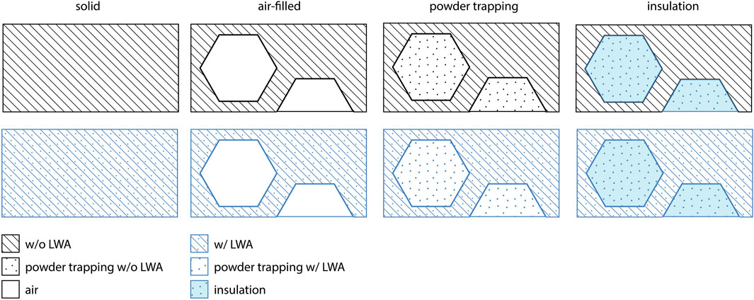
FIGURE 2. Illustration of different strategies for thermally enhanced AM wall elements: incorporating lightweight aggregates (LWA) into the AM material, creating air-filled internal cells, powder trapping of unbound aggregates, or adding insulation material into the cavities.
Cellular solids are intricate space-filling constructs characterized by a network of interconnected solid structures, such as struts or shells, forming the edges or faces of individual cells (Gibson and Ashby, 2001). Those can be open cells, like a honeycomb structure, or closed cells, like foams. Beyond their natural occurrences (e.g., wood, cork, or sponges), cellular solids have garnered significant attention in many industrial sectors due to their inherent porosity and commendable mechanical and thermal characteristics (Ashby, 2006).
Heat transfer through cellular solids is characterized by four principal phenomena: thermal conduction through the solid and the gas, radiation across the cells, and natural convection within the cells (see Figure 3). Each constituent plays a pivotal role, contributing to the overall thermal performance of the cellular structure (Gibson and Ashby, 2001).
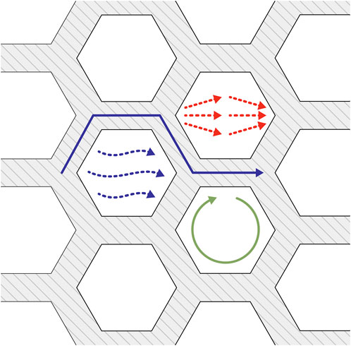
FIGURE 3. Heat transfer through cellular structures: radiative (red) and convective (green) heat transfer within the cells, and conductive heat transfer (blue) through the gas (dotted) and solid (continuous).
Generally, a low fraction of the solid phase and small cell size limits the thermal heat flow through cellular solids by suppressing convection and reducing radiation. However, natural convection is negligible only with cell diameters of less than 10 mm (Gibson and Ashby, 2001), which is hardly feasible with AM for construction.
Elaborating on this, Briels et al. (2022) proffered a meticulous examination of heat transfer mechanisms within cellular solids, particularly contextualized for an E3DCP application. This research delineated an analytical framework, offering profound insights into the thermal dynamics of a closed-cell typology.
Thermal insulation performance of monolithic AM elements with internal cell pattern is thus dependent on the material used, the fabrication aware constraints of the distinct AM processes as well as the cell geometry. Therefore, this research develops a workflow to evaluate these complex interdependencies, allowing a tool for decision-making when designing AM façade elements.
The reduction of thermal transmittance in construction materials is often achieved by enhancing their porosity due to the superior thermal properties of minuscule, air-filled pores within the material structure. Lightweight concrete, a well-known candidate for this strategy, can be produced through two predominant methodologies. The first involves the inclusion of lightweight coarse aggregates (LWA), while the second entails the addition of foaming agents. The latter approach culminates in what is popularly termed foamed concrete. On the other hand, the product of the former method is referred to as lightweight aggregate concrete (Strzałkowski et al., 2021).
A salient characteristic of lightweight concrete is its diminished density, which naturally attenuates the self-weight of the material. Moreover, these materials offer commendable thermal and acoustic insulation attributes without compromising their requisite mechanical strength (Cuevas et al., 2023). Among the diverse spectrum of lightweight aggregates employed in this domain, lightweight expanded glass aggregates (LEGA) and lightweight expanded clay aggregates (LECA) are predominantly utilized (Rashad, 2018; Adhikary et al., 2021).
In Additive Manufacturing, the conjunction of LWA with AM construction materials is an important research field to improve their material properties. The AM processes elucidated in Section 2.1 demonstrate this feasibility, emphasizing the potential to diminish the thermal conductivity of the resultant materials.
A literature review reveals numerous examples illustrating the versatility of integrating lightweight aggregates into AM materials. For instance, Weger et al. (2020) unveiled the potential of LEGA in the SCA process. Matthäus (2022) and Cuevas et al. (2023) investigated the use of LEGA in the CE3DP methodology, whereas Hechtl et al. (2023), specifically focusing on the new technique of NNM, are also using LEGA in their material mixture. Conversely, Rahul and Santhanam (2020) focused on extruding lightweight concrete using LECA. Strasser et al. (2024) tested LECA for the SPI technique, albeit using LEGA for this specific AM process also seems feasible.
The intrinsic properties of air reveal its potential as a thermal insulation medium. Fundamentally, air has a thermal conductivity value ranging between 0.02 and 0.03 W/mK (Häupl and Willems, 2013), which aligns closely with several conventional insulation materials. It is imperative, however, to differentiate between the inherent thermal conductivity of air as a gas and the complex heat transfer processes that occur within air-filled cells. Specifically, these cells witness the simultaneous occurrence of conduction, convection, and radiation - phenomena dictated by the cells’ geometric characteristics and the adjoining surfaces’ temperature gradients.
Closed-cell foams exhibit the lowest thermal conductivity among non-vacuum insulations (Gibson and Ashby, 2001). However, this is the case only with a limited solid phase volume fraction coupled with a cell size not exceeding 10 mm. Such specifications curtail thermal conduction through the solid phase and minimize convection and radiation within the cells. The implementation of closed cells is uniquely feasible through E3DCP. So far, with SCA or SPI, the unbound particles cannot be extracted either during the process due to the closed cells or after the fabrication.
Furthermore, E3DCP, while advantageous, has its limitations. The process encounters constraints in creating minuscule air-filled cavities with reduced solid phase volume fraction, particularly as smaller nozzle diameters impede the build-up rate. Recent advancements have seen Briels et al. (2022) conducting parametric optimization of a closed-cell typology for E3DCP application. Their efforts culminated in a design featuring a 60 mm cell diameter, an 800 mm cell height, and a 12 mm cell wall thickness. This design achieved a U-value of roughly 0.6 W/m2K with a solid material thermal conductivity of 0.38 W/mK (Briels et al., 2022). Despite these developments, the present study is primarily oriented toward exploring open cells, ensuring a consistent comparative framework across the three AM techniques.
Revisiting the discussions from Sections 2.1.1, 2.1.2, it is evident that both SCA and SPI face constraints related to the post-curing extraction of unbound particles. Encapsulating air within cellular structures (see 2.2.1) attenuates overall heat transfer. However, specific limitations impede the insulating effect of these air-filled cells. Using Lightweight Aggregates (LWA) in AM processes is promising in this context. LWAs inherently possess a relatively low thermal conductivity, as delineated in Section 2.2.2. This characteristic paves the way for a novel approach: “powder trapping” describes unbound particles maintained within the bound AM concrete structure. Such encapsulation curtails natural convection and radiation within these enclosures. While the relative share of thermal conduction through the solid phase might witness an uptick, the inherent porosity and low thermal conductivity of prevalent LWAs presumably lead to a net decrease in overall absolute heat transmission.
A nuanced evaluation of SCA and SPI’s potential benefits necessitates considering embodied carbon emissions. Predominantly, these emissions stem from the cement content of employed materials. Given the overarching objective of minimizing embodied carbon emissions, a reduction in cement content emerges as a priority. The SCA process, in which the cement resides in the powder bed, becomes restrictive. Retaining this cement through powder trapping leads to excessive cement content, amplifying embodied carbon emissions. Conversely, where cement is localized within the deposited paste, the SPI process allows for more flexibility. The unbound particles in this method primarily comprise LWAs, translating to considerably reduced embodied carbon emissions. Moreover, the inclusion of unbound particles augments structural rigidity. This attribute, particularly in intricate structures, can significantly facilitate the handling of prefabricated AM elements.
Monolithic AM elements present a unique opportunity for thermal enhancement by introducing insulation within internal cavities. Traditionally, loose-fill insulation has found application in diverse domains such as sloping roofs, technical installation voids, topmost floor slabs, and, notably, in the retrofitting of cavity walls (Zhivov, 2020). The deployment of this insulation involves either the use of specialized machinery blowing the material into the cavities to achieve the desired compression and density or directly pouring them into the voids (Zhivov, 2020).
The fibrous or granular materials used in this context include fiberglass, mineral wool, perlite, cellulose, EPS, and aerogel. Notably, the thermal conductivities of these materials span from 0.02 W/mK (aerogel) to 0.04 W/mK (cellulose, perlite). Within the ambit of monolithic AM elements, the prospect of utilizing loose-fill insulation is up-and-coming. This approach gains relevance, especially in scenarios where internal modifications for thermal optimization with air-filled cells are rendered unfeasible due to fabrication constraints or structural requisites. While incorporating additional insulation materials deviates from the mono-material construction stated in the prior approaches, it offers a distinct advantage. Unlike multi-layered composite systems, loose-fill insulation can be efficiently separated and extracted for sorted disposal or recycling after the end of life, ensuring sustainability.
All relevant material properties (Table 1) for the different processes and the evaluated variations of those (Table 3) are specified in an Excel spreadsheet. To enable a simulation-based parametric design workflow, this is imported into Grasshopper (Davidson, 2023), as depicted in Figure 4. Grasshopper, the core tool for this parametric study, is a graphical algorithm editor integrated into the CAD software Rhino3D (Robert McNeel and Associates, 2023). The geometry is generated using existing Grasshopper nodes and customized Python scripts, segmented for the simulation (see 2.3.2), and augmented with the thermal conductivity imported from the Excel file.
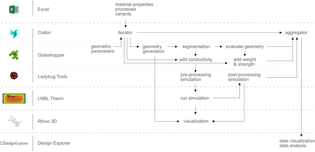
FIGURE 4. Schematic illustration of the software workflow illustrating the used software tools and the individual operations.
A plugin from Ladybug Tools LLC (2022) preprocesses the heat flux simulation and generates parametrically. xml-files, executed in THERM (LBNL, 2023). The postprocessing of the simulation results is again realized within Grasshopper: extracting the U-value and visualizing the resulting heat flux as a colored mesh in Rhino 3D. The geometry is evaluated in Grasshopper for dimensions, predominantly focusing on the surface areas of all cells and solid walls and the umax and vmax values. These values are then used to assess the ratio of the whole element’s solid ratio [%] and calculate the weight and a theoretical reference value for compressive strength. Therefore, the measured cell area and cell wall areas are multiplied by the according densities and compressive strength for each material imported from the Excel file. For the theoretical compressive strength C per meter wall length, only the solid material properties fc are considered and divided by the wall length l: C = (As * fc)/l.
Each unique variation is saved with an individual PNG file of the colored mesh. This is paired with a comprehensive record of all input and resulting parameters, saved in one CSV file using the Grasshopper plugin Colibri from Thornton Tomasetti Inc (2023). The CSV file can be matched with the PNG files and fed into Design Explorer (Thornton Tomasetti Inc, 2019), facilitating user-friendly, interactive data visualization and data analysis of the simulation results through its web-based Graphical User Interface (GUI). This is also accessible via repository (see Section 11), where the overall workflow and the results of the parametric study are available.
The geometry is parametrically generated in Grasshopper. As described, all material properties and variants are imported from the Excel file. These semantic parameters are supplemented with geometric constraints in Grasshopper, such as dimensions of the evaluated segment, u-count, v-count for the cells, and cell wall thickness. These constraints act as variables in generating the geometry, a basic two-dimensional, hexagonal pattern with the defined parameters, and offset each cell inwards to achieve the desired cell wall thickness. Due to specific restrictions of the simulation software LNBL THERM (see 2.3.3), all surface geometries with inner loops must be split. Therefore, segmentation is performed to rebuild the generated surface geometry. The segmented geometry for the cells, cell walls, and interior and exterior boundary curves are processed as described in 2.3.1.
LNBL THERM is primarily designed for simulating window details, encompassing relatively basic, mostly rectangular polygons. Our model presents intricacies, featuring sophisticated cell geometries unsuitable for such simulations due to several constraints. The comprehensive drawing guidelines are accessible in the THERM documentation (LBNL, 2000). Key constraints include:
• Avoid “Donuts” (inner loops) by subdividing the surrounding surface into multiple segments.
• Optimize the segmentation process. The current geometry generates a single surface for all cell walls segmented afterward. THERM demonstrates optimal compatibility with the fewest possible number of quadrilaterals and, where needed, triangles. Polygons with more vertices do work but are likely to trouble the simulation.
• Avoid sharp corners (angles <5°).
• Tweak the simulation mesh resolution. THERM creates a fine mesh using the finite element method (FEM) on the input geometries for the simulation. The mesh resolution can be adjusted by the Mesh-level, where some variants necessitate a value ≥8 while others require a value ≤7.
A predominant challenge involved generating a geometry compatible with the entire range of variants. Consequently, a persistent failure rate of approximately 4% was observed. These instances could not be aptly simulated, consistently yielding a U-value of 0 W/m2K.
Based on process restrictions outlined in 2.1.1 and 2.1.2, the AM processes SPI and SCA stipulate a necessity to operate exclusively with open cells. This is crucial to ensure the removal of unbound material from within the cells and influences the cell dimensions (
A variety of specifications is defined, as shown in Table 2. While the thermal boundary conditions (Interior and Exterior Temperature) are based on the standardized simulation values, the geometric constraints are set to cover a broad range of different cell densities to evaluate the effect of the internal cell geometry on the heat flux. The defined u-count and v-count, in combination with the cell wall thickness t (see Figure 5), have the main impact on the generative geometry generation. These geometric variations (in total 450 variations) are combined, as shown in Table 3, with ten combinations of the three AM processes, five material compositions (see Table 1) and three different insulation strategies for the cells (see Figure 2). This results overall in 4,500 variations.
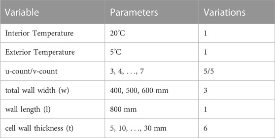
TABLE 2. Specifications for the parametric study.
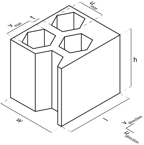
FIGURE 5. Geometric dimensions.
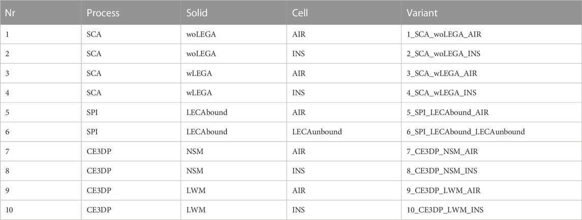
TABLE 3. Variations of AM process, material and insulation strategy for the parametric study.
The process returns three types of values, as shown in Figure 4, which are fed into the Colibri aggregator. The processed input information from the iterator (u-count, v-count, wall dimensions, variation), resulting evaluations (cell dimensions, cell area, weight, compressive strength), and the returned U-value from the simulation results. The aggregator writes all values into the result. csv file with the corresponding image files of the heat flux colored mesh as. png-files.
The thermal and structural requirements stated in the research questions are set to a U-value of 0.28 W/m2K resting on comparable legal requirements (see Section 1) and a theoretical reference value for compressive strength C of 2.7 MN/m. The second criterion is inspired by a German classification of compressive strength for bricks called “Steindruckfestigkeitsklasse” (SFK). Highly insulating bricks are commonly classified as SFK 6, indicating an average compressive strength of 7.5 N/mm2 for a brick and with a standard brick width of 365 mm, resulting in a theoretical value of 2.7 MN per meter wall length.
Two dimensional heat transfer simulations are used for horizontal wall geometry layers to assess thermal insulation performance. The simulation software LBNL THERM uses a two-dimensional heat transfer model based on a finite element method (FEM). In a mesh of discrete elements, the temperature variation is numerically solved by heat transfer equations derived from general energy equations, taking into account all four relevant heat transfer mechanisms (see 2.2.1). While thermal conductivity and radiation are calculated by the finite element solver with an additional view-factor-based radiation model, THERM approximates the convective heat transfer within the air cavities with heat transfer coefficients according to ISO 15099:2003. Therefore, an effective conductivity for convection within the cavities is calculated based on geometry, heat flow direction, surface emissivity, and temperatures. The geometry is, therefore, automatically simplified to equivalent rectangular cavities. To apply the correct boundary conditions, one must define the cross-section type (Wall–horizontal cross-section), a gravity vector (facing into the screen), and the so-called jamb cavity height (in this case, assuming 2.5 m for the wall height). (National Fenestration Rating Council, Inc, 2017).
Using a plug-in provided by ladybug tools, a generatively in Grasshopper designed geometry can be used, and material properties (thermal conductivity and emissivity) and boundary conditions (Temperature and convective heat transfer coefficient for interior and exterior) can be assigned to the geometry. This geometry is then handed to THERM for generating a mesh and running a finite element analysis solver. The heat transfer through the horizontal section is calculated, the heat flux and temperatures can be visualized, and a U-factor is determined. Overall this plug-in allows the use of these 2D heat flux simulations for large parameter studies fully integrated into a generative algorithm workflow.
The results of the parameter study are openly accessible via the repository link (see Section 11). They can be visualized and analyzed interactively via Design Explorer, as described in 2.3.1 and the repository’s readme.
To give a first overview, Figure 6 visualizes the input parameters
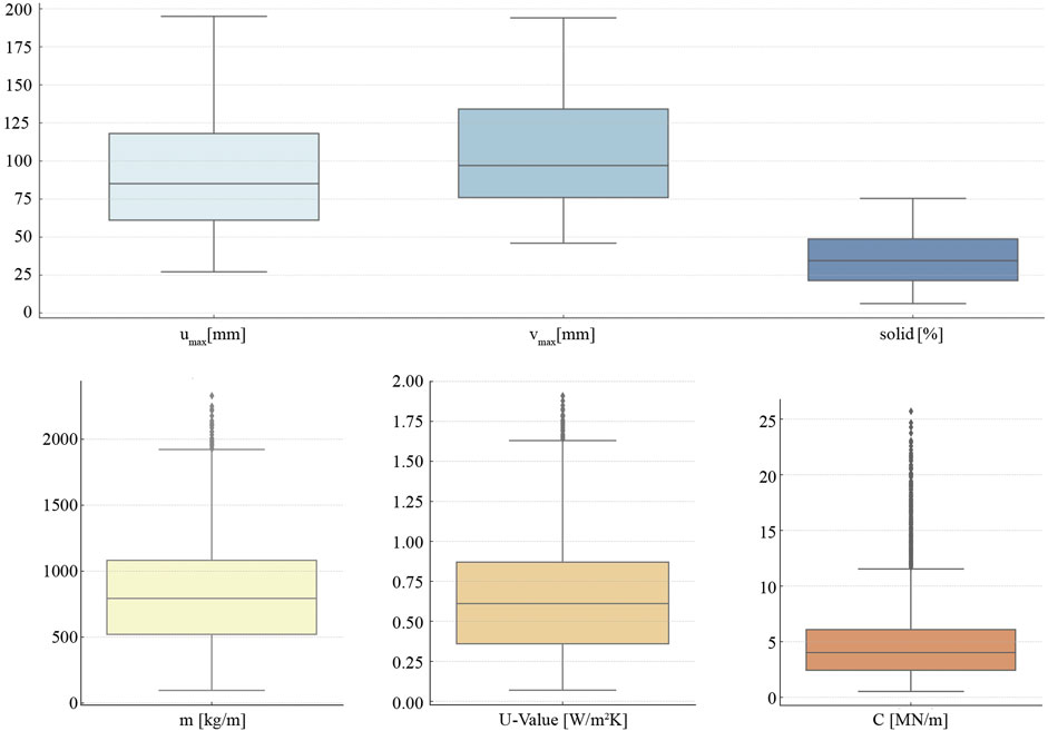
FIGURE 6. Box plot visualizations for input parameters umax and vmax, the evaluated variables solid ratio, theoretical compressive strength C, and mass m, and the resulting U-values.
Overall, the geometric specification via u- and v-count and the cell wall thickness result in cell sizes mostly between 61 and 134 mm and a solid ratio of 21%–49%. Calculating the resulting mass gives values ranging from 522 to 1,083 kg/m (Q1 to Q3). The theoretical compressive strength, evaluated according to the solid ratio and the material’s compressive strength, accounts for 50% of the elements with 2.5–6.1 MN/m. And the simulated U-values range from 0.36 W/m2K (Q1) to 0.87 W/m2K (Q3). Significantly, the value C has many Flier points, with values above the upper whiskers limit of 11.5 MN/m. This comes from the significantly higher compressive strength of the NSM (E3DCP), and similar to its higher thermal conductivity and density, produces statistical outliers on the upper bound for the U-value and the mass.
Proceeding with a closer examination of the thermal insulation performance of the variants, Figure 7 visualizes the resulting U-values in the so-called Heatmap plot, indicating the U-values as colored mesh (from dark blue ≤0.25 W/m2K to dark red ≥1.75 W/m2K), grouped by the variants (y-axis) with its correlation to the solid ratio (x-axis), describing the proportion of solid material to cell area (air or infill material). It is visible that the variations with air-filled gaps generally result in higher U-values (more yellow and red). In contrast, the variations with encapsulated insulation material or LWA mainly reduce thermal heat transfer (bluer). Furthermore, the trend is visible that generally, with a higher solid ratio (from left to right), the U-value is also increasing, which corresponds to the rising share of thermal conduction through the solid; thus, this trend is stronger (wider color range) for materials with high thermal conductivity (e.g., Var-1, -2 with SCA w/o LWA and Var-7, -8 with NSM). A subtler effect is observable for air-filled cells, where a local minimum for the U-value is around 12%–15% solid ratio, which can be traced back to the cell geometry with small cell size and thin cell wall thickness.
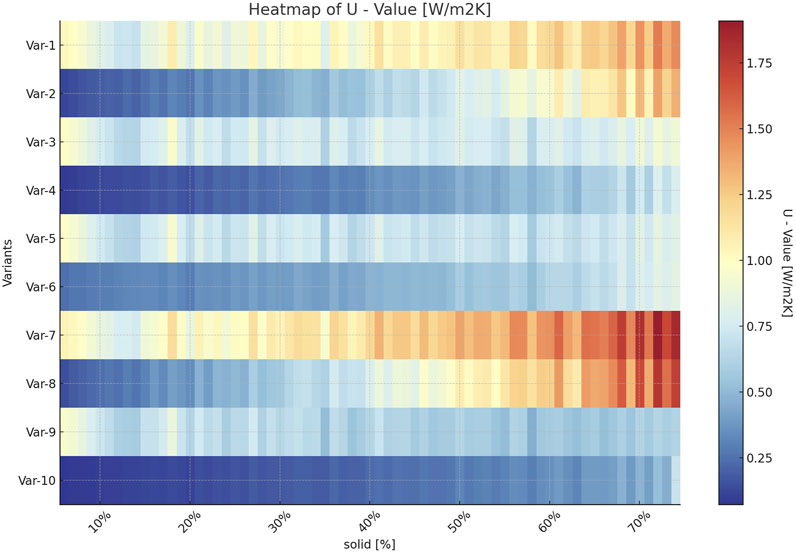
FIGURE 7. Heatmap visualizing the correlation between the ratio of solid material (x-axis) and the resulting U-value (colored mesh; from blue: low U-value to red: high U-value), grouped for the individual variants (y-axis).
Diving deeper into the evaluation of the individual variations, especially the resulting thermal insulation, some excerpts are documented in Table 4. The chosen variations are visualized in Figure 8, showing the resulting heat flux through the wall elements. The variants with the lowest U-value overall and specifically for air-filled cells are listed, where Var-9 and Var-10 are on top due to the lowest thermal conductivity of the material LWM. When adding the requirement for the theoretical compressive strength C > 2.70 MN/m, again, Var-10 is leading due to the combination of high compressive strength and low thermal conductivity. Var-6, a variant without additional insulation material, also achieves the requirements of U-value ≤0.28 W/m2K and C > 2.70 MN/m. The maximum C for U-value ≤0.28 W/m2K is reached by Var-8 due to the highest compressive strength of NSM.

TABLE 4. Excerpts of simulation results for various issues regarding the research questions.
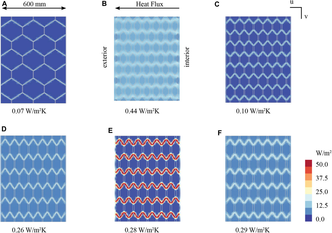
FIGURE 8. Selection of simulation results, visualizing the heat flux (from right to left) as colored mesh (blue: low heat flux density; red: high heat flux density) through a horizontal section of the wall elements relating to the selected parameter variations (A–F) depicted in Table 4 and listing the respective U-values.
To enable a deeper analysis of the correlations between geometric specifications, namely, the cell size umax and vmax and the solid ratio, and the resulting U-value, Figure 9 shows the results in a scatter plot matrix for all variants with air-filled cells (Group A; Var-1, 3, 5, 7, and 9), and Figure 10 visualizes it for all other variants with either additional insulation material or encapsulated unbound LWA (Group B; Var-2, 4, 6, 8, and 10). The plots show all results as data points, whereas the variants are grouped by color, and for each variant and variable, a polynomial regression (grade 4) is added. Additionally, a curve is visualizing the statistical distribution of the variables.
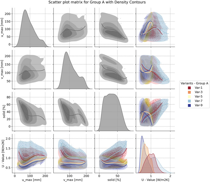
FIGURE 9. Scatter plot matrix for air-filled variants (Group A), showing the correlations between cell dimensions, solid ratio and U-value.
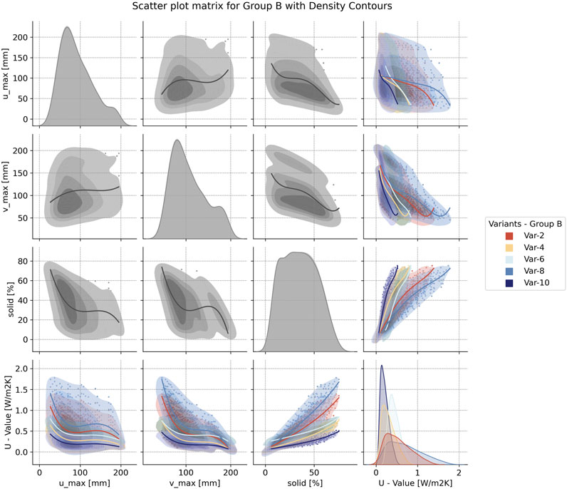
FIGURE 10. Scatter plot matrix for non-air-filled variants (Group B), showing the correlations between cell dimensions, solid ratio and U-value.
A trend is visible for the air-filled cells: a more minor cell size results in a lower U-value. In contrast, the correlation between umax is higher compared to vmax, indicated by steeper curves, which corresponds to the effect of reduced convection in smaller cells, especially in the direction of the heat flow. However, this trend is limited to a specific cell size, and a contrary effect leads to increasing U-values, especially for variants with already a lower level of thermal insulation due to higher thermal conductivity. This correlates with a higher solid ratio from small cell sizes combined with large cell wall thickness. Additionally, this aspect is visible for vmax, where the trend is either less or even reverse, that smaller cell size causes higher U-values, which again corresponds with a higher solid ratio. Overall, there´s a local optimum aiming to enhance thermal insulation at umax around 50–75 mm, depending on the variant. Focusing solely on the correlation between the solid ratio and U-value, especially for materials with high thermal conductivity (Var-1 and -7), an increase in the amount of solid material causes a substantial reduction of thermal insulation. But this effect is less for the other variants or even slightly reversed for Var-9 with generally a low U-value.
For Group B, where additional insulation material or LWA inside the cells is generally beneficial for reducing the heat flux, the principle is inverted since a large cell size corresponds with a large amount of insulation material and, thus, a low U-value. This is visible in Figure 10, where the trend for both umax and vmax indicates increasing thermal insulation performance for increasing cell size. This effect is apparent in the strong correlation between solid ratio and U-value.
Focusing merely on the correlation between C and the resulting U-value, Figures 11, 12 visualize thermal performance as a function of the theoretical compressive strength, both for Group A and Group B. This enables an evaluation of parameter variations for their applicability to specific load-bearing requirements. The plots show all simulation results in a scatter plot, grouped by color for the variants, and indicating the statistical density of the results with filled contours in color. Additionally, a linear regression evinces the correlation between U-value and C, showing a clear trend for most variants.
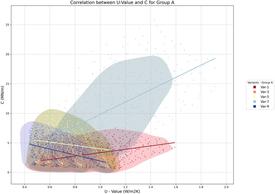
FIGURE 11. Scatter plot visualizing the correlation between U-value (x-axis) and theoretical compressive strength C (y-axis), representing all parameter variations of Group A as dots grouped by color according to the Variants, highlighting the statistical distribution of the results by filled contours, and indicating a linear regression for each Variant.
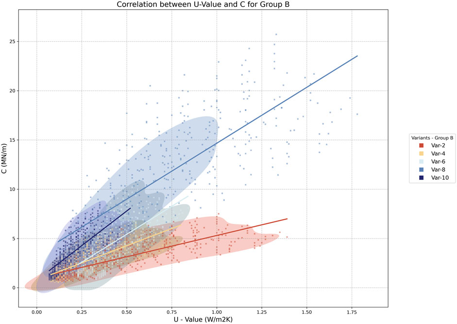
FIGURE 12. Scatter plot visualizing the correlation between U-value (x-axis) and theoretical compressive strength C (y-axis), representing all parameter variations of Group B as dots grouped by color according to the Variants, highlighting the statistical distribution of the results by filled contours, and indicating a linear regression for each Variant.
With higher values for C, the U-value also increases; thus, the thermal performance worsens. This is especially true for Var-7 and -8, stemming from the NSM material with the highest compressive strength and thermal conductivity in the field. Within the Group B, Var-4, -6, and -10 show the same trend but have a narrower range in U-values (Figure 12) since these are variants with encapsulated insulation material or LWA. The inclination of Var-1 and -2 is lower, and the range of U-values is larger. This is answerable to the SCA material’s high thermal conductivity but lower compressive strength without LWA. Finally, there are three variants where the trend is reversed, namely, Var-3, -5, and -9 from Group A (Figure 11). Those are the variants with air-filled cells and materials with low thermal conductivity; thus, the thermal performance is decreasing with larger cells, which also causes a lower solid ratio, which is also visible in Figure 9, and hence a lower theoretical compressive strength.
The primary research objective was to close the knowledge gap regarding thermally insulating monolithic AM wall elements by comparing different AM processes, materials, and insulation strategies. This was accomplished by examining the results synoptically. The posed research questions are stated and answered as follows:
What are different strategies to improve the thermal insulation of monolithic AM wall elements, and can their efficacy be verified?
The literature review showed several approaches to thermally enhance AM elements. Specifically, for monolithic AM wall elements, the following strategies are summarized, specific characteristics are assessed, and they´re further used for this research, including a holistic parametric study to evaluate their efficacy:
• Adapting the material composition by introducing Lightweight Aggregates (LWA)
• Adding an internal cell structure with air-filled cavities
• Encapsulating unbound LWA between the bound structure
• Incorporation of additional insulation material into the voids of the cell structure.
Based on the results of the parametric study, all four approaches can be verified as effective strategies to improve thermal insulation performance of monolithic AM wall elements. But when it comes to legal requirements for thermal insulation of the building envelope, the second strategy of encapsulating air within a cell structure is not achieving these thresholds under the given boundary conditions regarding AM processes, materials, and fabrication.
Which parameters influence the thermal insulation of AM wall elements with an internal cell structure, and what are measurable correlations?
Based on the broadly based parametric study, the results enable in-depth analysis and pave the way for a profound understanding of various correlations between the design of the internal structure and the thermal insulation performance. The results demonstrate that the correlation between the internal structure and the U-value depends on the insulation strategy. The variants with encapsulated insulation material or LWA are characterized by an increasing U-value for increasing the solid ratio since the thermal conductivity of the solid material is the driving factor. The cells’ shape has a subordinated influence since it only indirectly affects the solid ratio.
In contrast, the effect of the cell geometry on thermal heat transfer is significantly higher for air-filled cells and is inherently more complex. The solid ratio is, by definition, characterized by the cell geometry and the cell wall thickness. Thus, it likewise induces a change in the U-value. Still, a strong correlation is only visible for materials with high thermal conductivity (SCA w/o LWA and NSM), where thermal conductivity is mainly responsible for the overall thermal heat transfer. However, due to the interdependencies of cell geometry and heat transfer mechanisms through a cellular structure, the cell size in thermal flow direction is highly relevant. Considering the effect of a higher solid ratio for small cell size, there is a local optimum throughout all variants for umax around 50–75 mm.
What are the resulting parameters to achieve a U-value of at least 0.28 W/m2K while maintaining a reasonable theoretical compressive strength of at least 2.70 MN/m?
The parametric study reveals that only the variants with encapsulating insulation material or LWA (Group B) facilitate these specific requirements. The lowest U-value for the whole dataset is achieved by Var-10, with maximum cell size and lowest solid ratio, due to the lowest thermal conductivity of the LWM and the maximized amount of insulation infill. But, due to its highly delicate geometry, this is more of a theoretical variation, and its applicability in practice seems unfeasible. For air-filled cell structures, the overall top parameter variation regarding thermal performance pertains to Var-9, again with LWM and umax of 56–71 mm, achieving at least a U-value of 0.44 W/m2K and C ranging from 3.98–7.10 MN/m. The best thermal insulation with C > 2.70 MN/m is reached again by Var-10 with LWM, whereas the U-value accounts for 0.10 W/m2K and C equals 2.75 MN/m, tightly surpassing the threshold. The only variant complying with the requirements without additional insulation material is Var-6 with encapsulated unbound LECA. With a C of 3.30 MN/m, the best variation performs thermally very well with a U-value of 0.26 W/m2K. Maximizing the theoretical compressive strength, Var-8 wins the race with 11.38 MN/m, in line with the thermal requirement, and Var-6, without additional insulation material, achieves up to 3.86 MN/m. These highlighted variations all have a total wall width of 600 mm.
What combinations of AM processes, materials, and insulation strategies provide good synergy between thermal insulation and compressive strength?
Summarizing the answers to the preceding research question, it looks reasonable for the application of monolithic AM wall elements in practice to use E3DCP either with NSM (Var-8) or LWM (Var-10), adding additional insulation material inside the voids or to use SPI with bound and unbound LECA (Var-6). The second option might have advantages regarding a simpler construction process, better recyclability, and ecological aspects, which should be further examined in ensuing research.
Recapitulating the overall research goal, this study revealed a total number of 313 façade configurations, corresponding to 7% of the total number of 4,500 variations, in line with the specified thermal and structural requirements with a U-value of less than 0.28 W/m2K and a theoretical compressive strength exceeding 2.70 MN per meter wall length. This is achieved by variations based on all three different AM processes, with the largest proportion attributed to E3DCP at 80%, 17% to SCA, and 3% SPI. Adding additional insulation material into the cavities shows the most effective insulation strategy, accounting for 97% of all results, whereas encapsulating lightweight aggregates with SPI achieves these requirements with at least eight configurations, demonstrating its potential as the only mono-material solution in the field. Furthermore, the presented parametric design workflow, using 2D heat flux simulations as performance feedback, demonstrated its capabilities for a thorough multi-objective design optimization of monolithic AM wall elements.
• 313 variations (7%) with U-value ≤0.28 W/m2K and C ≥ 2.70 MN per meter wall length
• Effective variations: E3DCP and SCA with LWA and additional insulation material, and SPI with encapsulated unbound LWA
• Simulation-based parametric design workflow for multi-objective design optimization of monolithic AM wall elements
Besides the results of the parametric study as mentioned above, generating a thorough understanding and closing the knowledge gap regarding thermally enhanced monolithic AM wall elements, this research also aimed at evolving a workflow and toolset enabling these evaluations. This simulation-based parametric design approach, building upon generative modeling and performance feedback via parametric 2D heat flux simulations, allows for a holistic thermal evaluation and performance-driven design of intricate AM geometries. The developed workflow was now exemplified using one geometric pattern to achieve comparable results but can adapted and extended for other patterns. In general, this workflow and accumulated knowledge can now be used by researchers for further investigations, but it can also be used in tangible terms by designers to specifically design and realize thermally optimized AM components.
In the future, this workflow is supposed to be further developed and extended by multi-objective and multi-disciplinary approaches, especially combining the elaborate thermal with a more extensive structural analysis, by using coupled multi-physics FEM simulations and integrating them into a performance-driven parametric design approach. This enables, for instance, multi-criterial topology optimization for intricate internal structures of AM elements, following highly individualized structural force flow while optimizing its thermal performance. This must include further research, including a profound assessment of structural behavior including computational structural analysis and/or experimental testing and validation.
Building upon this and future research, the full potential of AM will be exploited, allowing for highly individualized multi-objective optimization approaches for functionally hybridized AM construction elements, aiming for a reduction of embodied and operational carbon emissions by reducing material use, and improving thermal performance as well as other building performance features such as thermal activation or thermal load management.
The datasets presented in this study can be found in online repositories. The names of the repository/repositories and accession number(s) can be found below: https://gitlab.lrz.de/amc_c03/2023_frontiers.
DB: Conceptualization, Data curation, Formal Analysis, Funding acquisition, Investigation, Methodology, Project administration, Resources, Software, Supervision, Validation, Visualization, Writing–original draft. MR: Writing–original draft, Data curation, Investigation, Software, Visualization. AN: Data curation, Writing–review and editing, Visualization. AS: Investigation, Resources, Writing–review and editing. MH: Resources, Writing–review and editing. MD: Writing–review and editing. BK: Resources, Writing–review and editing. PS: Resources, Writing–review and editing. FH: Investigation, Resources, Writing–review and editing. JF: Writing–review and editing. EK: Writing–review and editing. KD: Conceptualization, Funding acquisition, Supervision, Writing–review and editing. TA: Conceptualization, Funding acquisition, Supervision, Writing–review and editing.
The author(s) declare financial support was received for the research, authorship, and/or publication of this article. This research was funded by the Deutsche Forschungsgemeinschaft (DFG, German Research Foundation) - project number 414265976 - TRR 277.
The authors especially express their sincere gratitude to the whole team of TRR 277 AMC and its management, for the outstanding research environment. Regarding the work on the collaborative demonstrators, we want to pay tribute to all the students involved in the initial design of the demonstrators within the design studio AMtoARC, but also their engagement for the further development and realization of the demonstrator objects. Namely, we want to thank Mia Düpree and Mareen Fechner (Breuer X AM), Amber Alvarez and Elke Meiersonne (Building with Blocks), and Luisa Durst and MR (Marriage of two Materials). A special acknowledgement goes to our colleague and co-author AS and the Center for Building Materials at TUM, for running the experimental measurements on thermal conductivity. And last but not least, we want to appreciate the collaboration with additive tectonics GmbH, namely, BK, PS, Christian Thaler, and Christian Wiesner, for sharing their experiences from practice.
Authors BK and PS were employed by Additive Tectonics GmbH.
The remaining authors declare that the research was conducted in the absence of any commercial or financial relationships that could be construed as a potential conflict of interest.
All claims expressed in this article are solely those of the authors and do not necessarily represent those of their affiliated organizations, or those of the publisher, the editors and the reviewers. Any product that may be evaluated in this article, or claim that may be made by its manufacturer, is not guaranteed or endorsed by the publisher.
1https://matplotlib.org/stable/api/_as_gen/matplotlib.pyplot.boxplot.html.
Adhikary, S. K., Ashish, D. K., and Rudžionis, Ž. (2021). Expanded glass as light-weight aggregate in concrete – A review. J. Clean. Prod. 313, 127848. doi:10.1016/j.jclepro.2021.127848
Ashby, M. F. (2006). The properties of foams and lattices. Philosophical Trans. Ser. A, Math. Phys. Eng. Sci. 364, 15–30. doi:10.1098/rsta.2005.1678
Bos, F. P., Menna, C., Pradena, M., Kreiger, E., Da Silva, W. L., Rehman, A. U., et al. (2022). The realities of additively manufactured concrete structures in practice. Cem. Concr. Res. 156, 106746. doi:10.1016/j.cemconres.2022.106746
Bos, F., Wolfs, R., Ahmed, Z., and Salet, T. (2016). Additive manufacturing of concrete in construction: potentials and challenges of 3D concrete printing. Virtual Phys. Prototyp. 11, 209–225. doi:10.1080/17452759.2016.1209867
Briels, D., Kollmannsberger, S., Leithner, F., Matthäus, C., Nouman, A. S., Oztoprak, O., et al. (2022). Thermal Optimization of Additively Manufactured Lightweight Concrete Wall Elements with Internal Cellular Structure through Simulations and Measurements. Buildings 12, 1023. doi:10.3390/buildings12071023
Briels, D., Renz, M., Nouman, A., and Auer, T. (2023b). “Heat flux simulations for the AM facade demonstrator "Marriage of two Materials",” in Dataset (Munich, Germany: TUM). doi:10.14459/2023mp1716509
Briels, D., Renz, M., Nouman, A., and Auer, T. (2023a). “Heat flux simulations for the AM facade demonstrator,” in Breuer X AM. Dataset (Munich, Germany: TUM). doi:10.14459/2023mp1716507
Briels, D., Renz, M., Nouman, A., and Auer, T. (2023c). “Parametric heat flux simulations for the insulation concept of the AM facade demonstrator "Building with Blocks",” in Dataset (Munich, Germany: TUM). doi:10.14459/2023mp1716506
Bundestag, D. (2020). Gesetz zur Einsparung von Energie und zur Nutzung erneuerbarer Energien zur Wärme-und Kälteerzeugung in Gebäuden. Gebäudenergiegesetz - GEG.
Buswell, R. A., Leal de Silva, W. R., Jones, S. Z., and Dirrenberger, J. (2018). 3D printing using concrete extrusion: A roadmap for research. Cem. Concr. Res. 112, 37–49. doi:10.1016/j.cemconres.2018.05.006
Cuevas, K., Strzałkowski, J., Kim, J.-S., Ehm, C., Glotz, T., Chougan, M., et al. (2023). Towards development of sustainable lightweight 3D printed wall building envelopes – Experimental and numerical studies. Case Stud. Constr. Mater. 18, e01945. doi:10.1016/j.cscm.2023.e01945
Dahlenburg, M., Hechtl, C. M., Matthäus, C., and Fottner, J. (November 2022). “3D-Concrete Printing – Graded Concrete Extrusion,” in Proceedings of the 2022 3rd international conference on computation, automation and knowledge management. Dubai, United Arab Emirates, doi:10.1109/ICCAKM54721.2022.9990494
David, M., Freund, N., Dröder, K., and Lowke, D. (2023). The Effects of Nozzle Diameter and Length on the Resulting Strand Properties for Shotcrete 3D Printing PREPRINT. https://www.researchsquare.com/article/rs-3142213/v1.
Davidson, S. (2023). Grasshopper: algorithmic modeling for rhino. https://www.grasshopper3d.com/(Accessed September 7, 2023).
Deslot, Q., Pache, Y., Cartier Da Costa, I., Thiebaut, A., Jeannet, B., and Tudesq, M. (2020). Implementation of the EPBD France: status in 2020. https://epbd-ca.eu/wp-content/uploads/2022/10/Implementation-of-the-EPBD-in-France-%E2%80%93-Status-in-2020.pdf (Accessed August 22, 2023).
Dielemans, G., Briels, D., Jaugstetter, F., Henke, K., and Dörfler, K. (2021). Additive Manufacturing of Thermally Enhanced Lightweight Concrete Wall Elements with Closed Cellular Structures. JFDE 9, 59–72. doi:10.7480/jfde.2021.1.5418
Dörfler, K., Dielemans, G., Lachmayer, L., Recker, T., Raatz, A., Lowke, D., et al. (2022). Additive Manufacturing using mobile robots: opportunities and challenges for building construction. Cem. Concr. Res. 158, 106772. doi:10.1016/j.cemconres.2022.106772
Dörfler, K., Hack, N., Henke, K., and Kloft, H. (2023). AMC collaborative demonstrators: validation of integrated research methodologies through collaborative AMC prototyping. Braunschweig: Technische Universität Braunschweig.
Fleckenstein, J., Bertagna, F., Piccioni, V., Fechner, M., Düpree, M., Dacunto, P., et al. (September 2023). “Revisiting Breuer through Additive Manufacturing: passive solar-control design strategies for bespoke concrete building envelope elements,” in Proceedings of the 41st international conference on education and research in computer aided architectural design in europe (eCAADe 2023), Graz, Austria, 527–538. doi:10.52842/conf.ecaade.2023.1.527
Gibson, L. J., and Ashby, M. F. (2001). Cellular solids: structure and properties. Cambridge, England: Cambridge Univ. Press.
Häupl, P., and Willems, W. M. (2013). Lehrbuch der Bauphysik: schall - wärme - feuchte - licht - brand - klima. Wiesbaden, Germany: Springer Vieweg.
Hechtl, C. M., Kränkel, T., and Gehlen, C. (September 2023). “Near-Nozzle Mixing for Additive Manufacturing of Cementitious Mortar: A Homogeneity Study,” in Proceedings of the 21st international conference on building materials Weimar, Germany.
Hepf, C., Overhoff, L., Koth, S. C., Gabriel, M., Briels, D., and Auer, T. (2023). Impact of a Weather Predictive Control Strategy for Inert Building Technology on Thermal Comfort and Energy Demand. Buildings 13, 996. doi:10.3390/buildings13040996
Herding, F., Strasser, A., Briels, D., Lowke, D., and Kränkel, T. (2023). “Experimental results for mechanical and thermal properties of SCA material,” in Dataset (Munich, Germany: TUM). doi:10.14459/2023mp1720074
ICC (2021). International Energy Conservation Code. https://codes.iccsafe.org/content/IECC2021P1 (Accessed August 22, 2023).
Knaack, U., and Koenders, E. (2018). Building physics of the envelope: principles of construction. Basel: Birkhäuser.
Ladybug Tools Llc, (2022). Ladybug Tools. https://www.ladybug.tools/(Accessed September 7, 2023).
LBNL. (2000). THERM Drawing Tips. https://windows.lbl.gov/sites/default/files/Downloads/chapter10.pdf [Accessed August 16, 2023].
LBNL (2023). THERM Software Downloads. https://windows.lbl.gov/therm-software-downloads (Accessed September 7, 2023).
Leschok, M., Cheibas, I., Piccioni, V., Seshadri, B., Schlüter, A., Gramazio, F., et al. (2023). 3D printing facades: design, fabrication, and assessment methods. Automation Constr. 152, 104918. doi:10.1016/j.autcon.2023.104918
Lim, J. H., Weng, Y., and Pham, Q.-C. (2020). 3D printing of curved concrete surfaces using Adaptable Membrane Formwork. Constr. Build. Mater. 232, 117075. doi:10.1016/j.conbuildmat.2019.117075
Lima, L., Trindade, E., Alencar, L., Alencar, M., and Silva, L. (2021). Sustainability in the construction industry: A systematic review of the literature. J. Clean. Prod. 289, 125730. doi:10.1016/j.jclepro.2020.125730
Lopes, L., Almeida, M., and Reis, D. (2023). Influence of 3D microstructure for improving the thermal performance of building façades. IOP Conf. Ser. Earth Environ. Sci. 1196, 012064. doi:10.1088/1755-1315/1196/1/012064
Mai, I., Herding, F., and Lowke, D. (June 2022). “Evaluating the Effect of Methyl Cellulose on Hardened State Properties in Selective Cement Activation,” in Proceedings of the Third RILEM international conference on concrete and digital fabrication: dc 2022, Loughborough, UK, 289–295. doi:10.1007/978-3-031-06116-5_43
Marais, H., Christen, H., Cho, S., Villiers, W. de, and van Zijl, G. (2021). Computational assessment of thermal performance of 3D printed concrete wall structures with cavities. J. Build. Eng. 41, 102431. doi:10.1016/j.jobe.2021.102431
Matthäus, C. I. I. (2022). Performance under pressure: effect of pumping pressure on additive manufacturing of lightweight aggregate concrete. Munich, Germany: Technical University of Munich.
National Fenestration Rating Council, Inc, (2017). THERM 7/WINDOW 7 NFRC Simulation Manual. https://windows.lbl.gov/sites/default/files/Downloads/NFRCSim7-July2017.pdf (Accessed August 1, 2023).
Paolini, A., Kollmannsberger, S., and Rank, E. (2019). Additive manufacturing in construction: A review on processes, applications, and digital planning methods. Addit. Manuf. 30, 100894–100913. doi:10.1016/j.addma.2019.100894
Pessoa, S., Guimarães, A. S., Lucas, S. S., and Simões, N. (2021). 3D printing in the construction industry - A systematic review of the thermal performance in buildings. Renew. Sustain. Energy Rev. 141, 110794. doi:10.1016/j.rser.2021.110794
Piccioni, V., Leschok, M., Lydon, G., Cheibas, I., Hischier, I., Dillenburger, B., et al. (2023). Printing thermal performance: an experimental exploration of 3DP polymers for facade applications. IOP Conf. Ser. Earth Environ. Sci. 1196, 012063. doi:10.1088/1755-1315/1196/1/012063
Rahul, A. V., and Santhanam, M. (2020). Evaluating the printability of concretes containing lightweight coarse aggregates. Cem. Concr. Compos. 109, 103570. doi:10.1016/j.cemconcomp.2020.103570
Rashad, A. M. (2018). Lightweight expanded clay aggregate as a building material – An overview. Constr. Build. Mater. 170, 757–775. doi:10.1016/j.conbuildmat.2018.03.009
Riba, (2021). The buildings regulations 2010. Approved document L - conservation of fuel and power. London, England: RIBA Publishing.
Richter, C., and Jungwirth, J. (May 2023). “Mechanische Eigenschaften mittels selektiver Zementaktivierung gedruckter Betonbauteile,” in Proceedings of the 19th Rapid.Tech 3D conference erfurt, Germany, 134–143. doi:10.3139/9783446479425.012
Robert McNeel and Associates, (2023). Rhinoceros: design, model, present, analyze, realize. https://www.rhino3d.com/(Accessed September 7, 2023).
Schutter, G. de, Lesage, K., Mechtcherine, V., Nerella, V. N., Habert, G., and Agusti-Juan, I. (2018). Vision of 3D printing with concrete — Technical, economic and environmental potentials. Cem. Concr. Res. 112, 25–36. doi:10.1016/j.cemconres.2018.06.001
Shakor, P., Gowripalan, N., and Rasouli, H. (2021). Experimental and numerical analysis of 3D printed cement mortar specimens using inkjet 3DP. Arch. Civ. Mech. Eng. 21, 58–16. doi:10.1007/s43452-021-00209-3
Strasser, A., Briels, D., Kränkel, T., Gehlen, C., and Auer, T. (2023). “Selective Paste Intrusion - An Additive Manufacturing Technique to Produce Customized Building Components with Enhanced Thermal Insulating Performance,” in Proceedings of the HiPerMat 2024 6th international symposium on ultra-high performance concrete and high performance materials.
Strasser, A., Briels, D., Kränkel, T., Sonnleitner, P., Wiesner, C., and Knychalla, B. (2023). “Thermal conductivity assessement of SCA material with lightweight expanded glass aggregate,” in Dataset (Munich, Germany: TUM). doi:10.14459/2023mp1720075
Strzałkowski, J., Sikora, P., Chung, S.-Y., and Abd Elrahman, M. (2021). Thermal performance of building envelopes with structural layers of the same density: lightweight aggregate concrete versus foamed concrete. Build. Environ. 196, 107799. doi:10.1016/j.buildenv.2021.107799
Suntharalingam, T., Upasiri, I., Gatheeshgar, P., Poologanathan, K., Nagaratnam, B., Santos, P., et al. (2021). Energy Performance of 3D-Printed Concrete Walls: A Numerical Study. Buildings 11, 432. doi:10.3390/buildings11100432
Thornton Tomasetti Inc. (2019). Design Explorer 2. http://tt-acm.github.io/DesignExplorer/(Accessed September 7, 2023).
Thornton Tomasetti Inc. (2023). TT Toolbox for Grasshopper. https://www.thorntontomasetti.com/capability/tt-toolbox-grasshopper (Accessed September 7, 2023).
Weger, D., Kim, H., Talke, D., Henke, K., Kränkel, T., and Gehlen, C. (July 2020). “Lightweight Concrete 3D Printing by Selective Cement Activation – Investigation of Thermal Conductivity, Strength and Water Distribution,” in Proceedings of the second RILEM international conference on concrete and digital fabrication: digital concrete 2020, Eindhoven, Netherlands, 162–171. doi:10.1007/978-3-030-49916-7_17
Zhivov, A. (2020). Deep energy retrofit: a guide to achieving significant energy use reduction with major renovation projects. Cham, Germany: Springer International Publishing AG.
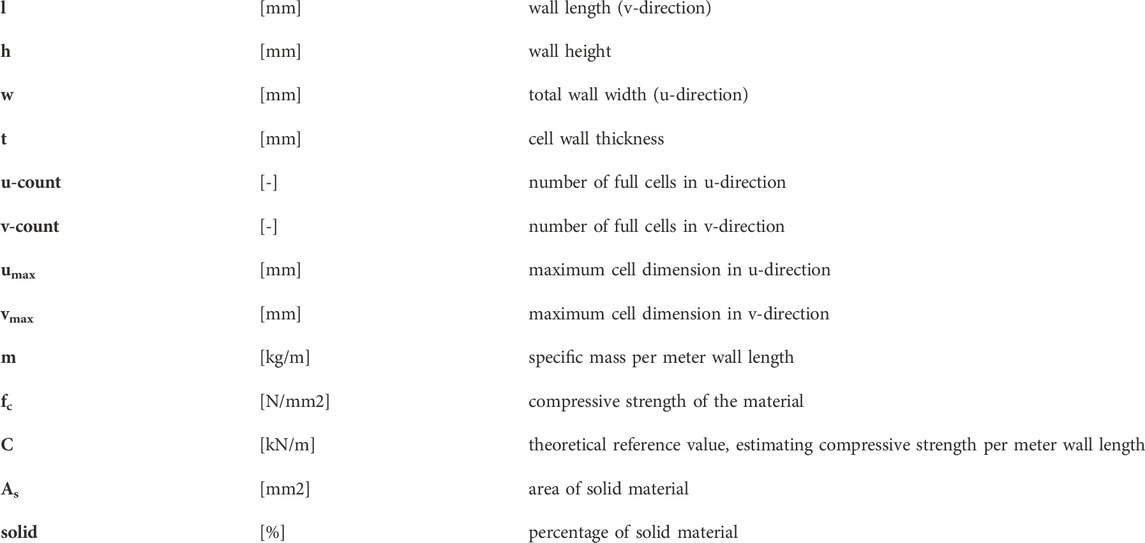
Keywords: additive manufacturing in construction, thermal insulation, functional hybridization, parametric design, heat flux simulation, selective paste intrusion, selective cement activation, extrusion 3D concrete printing
Citation: Briels D, Renz M, Nouman AS, Straßer A, Hechtl M, Dahlenburg M, Knychalla B, Sonnleitner P, Herding F, Fleckenstein J, Krakovská E, Dörfler K and Auer T (2023) Monolithic AM façade: multi-objective parametric design optimization of additively manufactured insulating wall elements. Front. Built Environ. 9:1286933. doi: 10.3389/fbuil.2023.1286933
Received: 31 August 2023; Accepted: 28 September 2023;
Published: 17 October 2023.
Edited by:
Pshtiwan Shakor, Sulaimani Polytechnic University, IraqReviewed by:
Mehran Khan, University College Dublin, IrelandCopyright © 2023 Briels, Renz, Nouman, Straßer, Hechtl, Dahlenburg, Knychalla, Sonnleitner, Herding, Fleckenstein, Krakovská, Dörfler and Auer. This is an open-access article distributed under the terms of the Creative Commons Attribution License (CC BY). The use, distribution or reproduction in other forums is permitted, provided the original author(s) and the copyright owner(s) are credited and that the original publication in this journal is cited, in accordance with accepted academic practice. No use, distribution or reproduction is permitted which does not comply with these terms.
*Correspondence: David Briels, ZGF2aWQuYnJpZWxzQHR1bS5kZQ==
Disclaimer: All claims expressed in this article are solely those of the authors and do not necessarily represent those of their affiliated organizations, or those of the publisher, the editors and the reviewers. Any product that may be evaluated in this article or claim that may be made by its manufacturer is not guaranteed or endorsed by the publisher.
Research integrity at Frontiers
Learn more about the work of our research integrity team to safeguard the quality of each article we publish.