
94% of researchers rate our articles as excellent or good
Learn more about the work of our research integrity team to safeguard the quality of each article we publish.
Find out more
ORIGINAL RESEARCH article
Front. Built Environ., 07 December 2023
Sec. Construction Materials
Volume 9 - 2023 | https://doi.org/10.3389/fbuil.2023.1269000
This article is part of the Research TopicAdditive Manufacturing in ConstructionView all 6 articles
 Philipp Rennen1*
 Stefan Gantner1
 Gido Dielemans2Lazlo Bleker3Nikoletta Christidi4Robin Dörrie1Majid Hojjat5
 Inka Mai6,7Karam Mawas8Dirk Lowke6
 Pierluigi D’Acunto3
 Kathrin Dörfler2
 Norman Hack1
 Mariana Popescu4
The research project presented here aims to develop a design-informed manufacturing process for complex concrete shell structures in additive manufacturing and thus overcome limitations of traditional construction methods such as formwork- and labor intensity. To achieve this, an effort was made to merge the two technologies of CNC knitted stay-in-place formwork, known as KnitCrete, and robotically applied shotcrete, known as Shotcrete 3D Printing (SC3DP), and thereby reduce their respective limitations. The proposed workflow unites both digital fabrication methods into a seamless process that additionally integrates computational form finding, robotically applied fiber reinforcement, CNC post processing and geometric quality verification to ensure precision and efficiency. As part of a cross-university, research-based teaching format, this concept was implemented in the construction of a full-scale pedestrian bridge, which served as a demonstrator to evaluate the capabilities and limitations of the process. While overcoming some challenges during the process, the successful prove of concept shows a significant leap in digital fabrication of complex concrete geometry, reducing reliance on labor-intensive methods. The results shown in this paper make this fabrication approach a promising starting point for further developments in additive manufacturing in the construction sector.
The production of complex geometries has always been a challenge in the construction industry, but it is still worth striving to make them achievable, as freedom of form not only offers architectural freedom of expression but also structural advantages (Moussavi and Daniel, 2009). Shell structures, for example, offer a great deal of design freedom and can span large distances. By adjusting the shell geometry, the structure can be thinner overall and thus save material, which is mostly wood or concrete. Historically, those beneficial forms were found, for example, using physical hanging-chain-models as Frei Otto did to design the wooden grid shell of the Multihalle Mannheim (Otto, 1975) according to the uniform gravitational force on the chains (Liddell, 2015). Computer-aided design has contributed to the fact that a shell’s geometry can be adjusted to expected loads during the planning phase to offer optimum material efficiency (Saleh, 1987; Pellegrino et al., 2024).
Besides wood, concrete is used most commonly, not only due to its strength and affordability but also its ability to be casted in any ever so complex shape. Although concrete shell structures were designed to bring advantages in terms of material consumption they proved to be difficult to manufacture and hence barely economically viable, as it involves a large amount of customized formwork (Chudley and Greeno, 2006) and a high level of manual labor (Brucker et al., 2021). An example for concrete shell architecture is the National Taichung Theater by Toyo Ito & Associates (Toyo Ito and Associates, 2014), where shotcrete used to be sprayed directly onto prefabricated, dense reinforcement cages, likewise a labor-intensive process that also generates a significant amount of waste material but less formwork compared to casting. The emergence of digital fabrication in the construction sector is now opening up new opportunities to efficiently manufacture this type of complex geometry (Gramazio and Kohler, 2013).
The project presented here is based on a combination of two innovative digital concrete construction technologies that have been developed independently in recent years: firstly, the fabrication of flexible CNC-knitted stay-in-place formworks for the efficient production of thin concrete shells (Popescu, 2019), and secondly, robotic Shotcrete 3D Printing (SC3DP) (Kloft et al., 2019), which was developed at the TU Braunschweig. Within the framework of the Collaborative Research Centre TRR 277 (“TRR 277 - Additive Manufacturing in Construction AMC TRR277” 2023), which aims to examine Additive Manufacturing as a novel digital manufacturing technology for the construction industry, the opportunity arose to digitally design, plan and fabricate a large scale demonstrator in a collaborative teaching format between the TU Munich, the TU Braunschweig and the TU Delft, illustrating the symbiosis of the two technologies. This unique combination could potentially eliminate the disadvantages of excessive waste, high labor costs and corrosion on one hand, and significantly extend the design space of additive manufacturing on the other hand.
Throughout the 20th century, tensioned textiles were employed as formwork for concrete, resulting in an overall reduction of material consumption and waste (Veenendaal, West, and Block, 2011; Hawkins et al., 2016). However, so far the use of woven textiles as formwork has necessitated extensive amounts of manual labor for cutting and assembling different 2D fabric patches into a continuous geometry (Popescu, 2019).
The introduction of CNC-knitted textiles in fabric formwork systems has the potential to overcome these challenges. Knitted textiles offer precise specification at a unit level and can integrate multiple fibers with distinct properties into a single continuous material (Thomsen and Hicks, 2008). They can be customized to conform to doubly curved and three-dimensional shapes, and their design can include specific local properties, channels, grooves, and openings. Consequently, the need for manual assembly of multiple parts to achieve the desired geometry and mechanical behavior is eliminated. The use of CNC knitting machines in fabricating knitted textiles reduces costs and labor associated with manufacturing intricate formwork components (Popescu, 2019).
The KnitCandela prototype (Figure 1) served as a demonstration of the applicability of weft-knitting on a large architectural scale, highlighting its significant implications in terms of formal expression, weight and waste reduction, labor efficiency, and cost-effectiveness (Popescu et al., 2021).
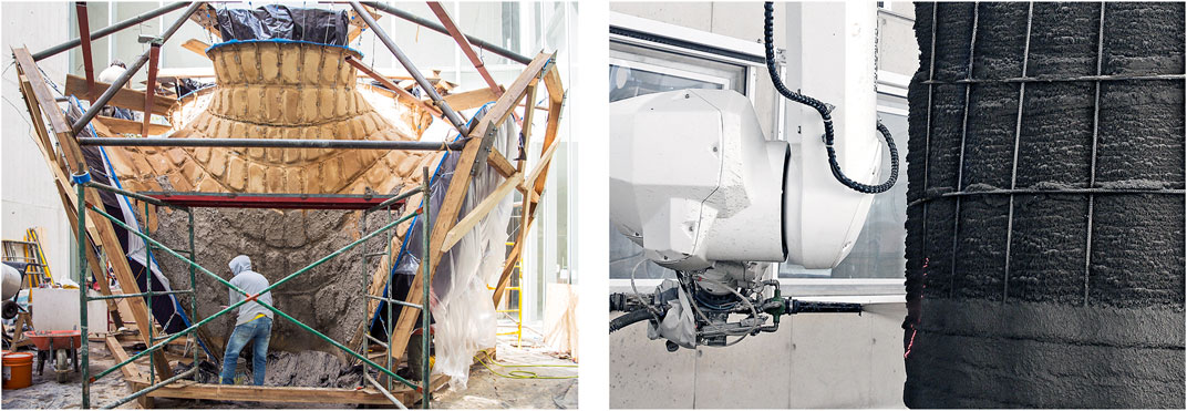
FIGURE 1. Left: Manual concreting of the knitted, stay-in-place formwork of KnitCandela (Popescu et al., 2021), right: Vertical SC3DP to on a printed wall surface to embed reinforcement (Hack and Kloft 2020).
Despite the increased efficiency in the production of the textile formwork, the manual concreting process using shotcrete still remains labor-intensive, and its precision is highly dependent on the skill of the nozzleman. Manual shotcrete, a technique with a rich history dating back to the early 20th century (Kovári, 2003), involves the skilled application of concrete through a high-velocity nozzle.
The pioneering work of Pier Luigi Nervi, expressed in the introduction of “Ferrocement” (Leslie, 2017; Naaman, 2000), demonstrated the suitability of shotcrete for the design of free-form elements without the need for extensive formwork. This turning point in architectural technology opened the door for shotcrete to play a central role in a number of iconic building projects and diverse applications. Notable early examples include Pier Luigi Nervi’s Exhibition Hall for the Turin Motor Show in 1948 (Greco, 2008) and Félix Candela’s Los Manantiales Restaurant in Xochimilco in 1958 (Lugowski, 2013). Nevertheless, the method is not without its constraints, requiring a high degree of skill and expertise, and the manual nature of the process often leads to irregularities in the quality and finish of the concrete surface.
The technology of SC3DP (Figure 1), currently being researched at TU Braunschweig (Hack and Kloft, 2020), presents a promising solution that can address the labor-intensive process of concreting with knitted formwork, as apparent in the KnitCandela project. Shotcrete 3D Printing (SC3DP) is a depositioning additive manufacturing technique based on a wet-mix shotcrete process. It is classified as a material jetting process (Buswell et al., 2020) and is characterized by the deposition of fine grain concrete or cement paste while adding pressurized air in the nozzle.
The material application using spraying has various advantages, such as strong layer bonding (Kloft et al., 2020), variable nozzle to strand distance (Dressler et al., 2020; Lachmayer et al., 2023), embedding of reinforcement with homogeneous bonding zones (Freund and Lowke, 2022), and continuous grading of layer thicknesses (Rennen et al., 2021).
Additionally, SC3DP offers the flexibility to use different materials for specific purposes. This enables both the application of thin surface coatings and the selective build-up of structural mass using distinct materials, depending on the requirements of the project. The SC3DP technology presents a fault-tolerant and efficient process for spraying concrete from a distance, thus it is especially suited for the actual use case of coating initially flexible print beds that may deform under minimal loads.
In constant interaction with the design, the fabrication sequence was developed, which encompasses the computational form finding of a base surface, a structural analysis and optimization procedure, and the precise dimensioning of structural components for the specific use case of a pedestrian bridge. As a result, the following overall fabrication concept for substructure, textile formwork and concrete as well as reinforcement application has been established (Figure 2).
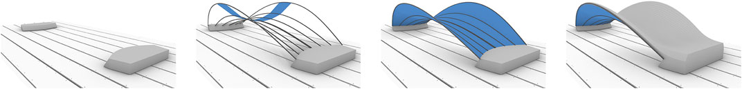
FIGURE 2. Left to right: Foundation placement, Bending active steel rods, Spanning of 3D-knitted formwork, Robotic Shotcrete.
A proven state-of-the-art methodology for a KnitCrete prototype of a concrete shell bridge was adopted for the textile-spanning substructure (Popescu et al., 2018a). Accordingly, the substructure was considered integrally in the bridge design, so that it could support the textile by itself in order to avoid auxiliary wooden frames. An approach based on “active bending” was chosen, in which the textile is tensioned into shape by elastically bent rebars, which are laterally braced by steel cables. To achieve this the rebars are passed through channels in the textile and then anchored into the previously cast foundations.
The geometry and exact position of this assembled structure are determined through 3D scanning. The robotic paths for all automated fabrication steps are subsequently generated based on the textiles real world shape. This ensures accurately tailored execution of the robotic fabrication steps.
In a first concreting step, the textile is coated by spraying a thin layer of light cement paste onto it to gain initial stiffness of the formwork. The aim of this treatment is to increase the load-bearing capacity for further concrete application. Subsequently, continuous glass fiber is wound dynamically around the previously attached pins in a specifically targeted layer above the base surface of the bridge. Afterwards, concrete is sprayed onto the formwork with locally varying thicknesses, determined through structural analysis. The concrete is distributed in its wet state to structure the surface, and finally, after curing, the edges of the bridge are being milled to precision.
After finished fabrication of the bridge itself, an auxiliary steel girder frame, which can be attached to the foundations temporarily, prevents damage during transportation.
The computational form finding procedure employed in this research project can be split into two phases. First, bending-active beams in the form of bundles of steel rebars are form-founded and arranged in space, resulting in the structural skeleton of the bridge. This skeleton is then converted into a continuous shell geometry by form-finding the knitted textile spanning in between the rebars of the structural skeleton. The knitted textile acts as a lost formwork for concrete shotcrete. Eventually, a local thickness optimization of the concrete shell is carried out (Figure 3).
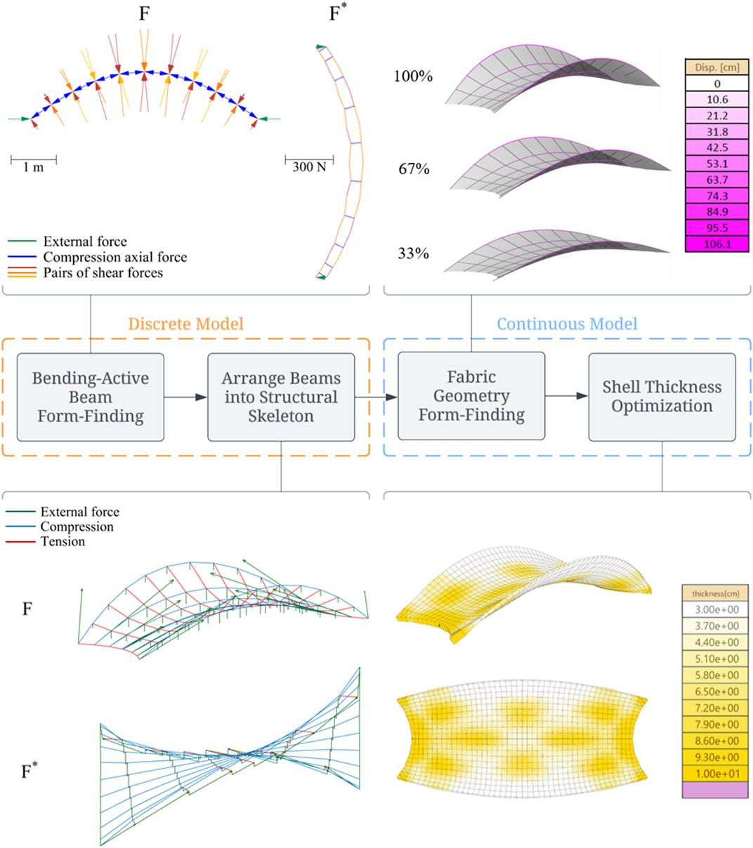
FIGURE 3. Computational design procedure consisting of a discrete and a continuous design phase.
Bending-Active Beams First, the geometry of the bending-active beams is simulated using a geometrically non-linear analysis based on the FEM solver Karamba 3D (Preisinger, 2020). Results are subsequently verified through graphic statics for bending-active structures (Boulic et al., 2020). The beams consist of bundles of three steel bars with a diameter of 12 mm, which are initially straight. Each rebar is bent individually before being bundled in groups of three to minimize internal strain energy and prevent the material from yielding.
Structural Skeleton The structural skelethon, consisting of eight bundles of bent rebars, is designed to withstand the weight of the unhardened concrete shell. The internal forces within the concrete shell are analyzed using vector-based 3D graphic statics (D’Acunto et al., 2019; Konstantatou, D’Acunto, and McRobie, 2018). The arrangement and degree of bending of the beams is set up parametrically in a way that gives control over the overall shape of the resulting shell. Parameters of the model include.
• The original length of the rebars Li, determining the rise of the arch at different points along the width of the bridge.
• The rotation of the bars around their own axis Θi, determining the degree to which the bridge fans either inwards or outwards towards the middle of the span.
• The curvature distance of the abutments d, enabling the base of the bridge to bend either inward, outward, or be completely straight.
The design space generated by varying these parameters was manually explored and the parameters were set to values that maximize structural performance of the final concrete shell while fulfilling the architectural requirements, including aesthetic appeal. Throughout the exploration, a uniform thickness assumption for the concrete shell was maintained.
Geometry Form-Finding The geometry of the fabric formwork was form-found with EQlib (Oberbichler, 2019) by prestressing a membrane between the elements of the structure. This configuration creates a prestressed gridshell (Cao et al., 2021) that carries the load of the unhardened concrete.
Thickness Optimization After finalizing the global geometry, the thickness of the shell was optimized for different design loads. This optimization process considered three specific load cases.
• A uniform load applied across the entire walking area of the bridge, which refers to a strip in the center of the bridge where the inclination makes the area more walkable compared to the edges.
• A uniform load applied on half of the walking area, cutting along the direction of the bridge, with both symmetries taken into account.
• A uniform load applied on half of the walking area, cutting perpendicular to the direction of the bridge, with both symmetries considered.
To determine the final thickness distribution, an envelope of the optimized thickness values for all the considered load cases was created. This envelope encapsulated the range of thicknesses that yielded the best structural performance.
By following this computational design procedure, which encompassed the simulation of beam geometry, the design of the global geometry, manual exploration of parameters, thickness optimization for various design loads, and determination of the final thickness map, the researchers achieved an optimized bridge design that fulfilled both structural and architectural requirements.
The 3D knitted textile formwork was created based on the previously generated double-curved base surface of the bridge. The base unit of 3D knits is called a loop, which is created by pulling a yarn with a needle through a previously formed loop. The 3D knitted shaped textiles are produced in a sequential manner course by course. Each course is made up of several loops created by a series of needles on the machine. To create instructions for the machine, loops and their arrangement in courses need to be generated for the desired geometry. Therefore, a first step is determining the size of the loops within the textile. Their size is dependent on machine parameters (such as gauge and tension while knitting), yarn parameters (such as diameter), and tensioning of the final produced textile within the formwork. Calibration of the model through testing knit material samples is essential to ensure accurate loop dimensions. To determine the loop size, test samples are made with the desired textile meso-scale architecture, tensioned to the desired degree and the loop size is measured. This measured size becomes the input for an automated pattern generation method (Popescu et al., 2018b) employed to create the knitted formwork for sophisticated double-curved shapes. In the case of the bridge demonstrator the geometry is split into two symmetric sub-surfaces, following the longitudinal mirror axes of the bridge (Figure 4). Patterns are generated only for one of the quarters and subsequently mirrored and joined to form the entire pattern for production. Within the quarter of the bridge geometry patches are further defined in strips that represent the area between two rebar splines. The pattern generation steps are then carried out for each patch as described below.
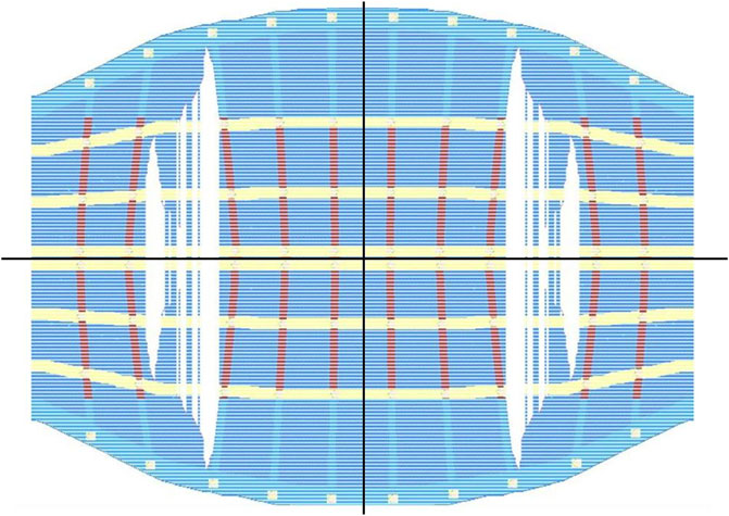
FIGURE 4. Parametrically defined 2D Knitting Pattern of the presented Bridge’s Formwork.
To generate the instructions for the machine courses need to be generated for each of the patch surfaces defined in the previous step. To do this, each patch is contoured with the loop height as spacing parameter. Then, to define the number and arrangement of loops within each course, they are further divided considering the loop width. With all loops generated onto the 3D geometry, they can now be translated to a 2D knitting pattern, The pattern contains information about various machining operations which produce functional channels and holes within the final produced textile. The placement of each of these functional features is done automatically but identifying features on the 3D version of the knitting pattern.
In order to maintain the geometry of the elastically spanned textile, the stiffening coating material needs to be light and grain free. Therefore it consists of ordinary Portland cement CEM I 42.5 R (OPC; HeidelbergCement, Ennigerloh-Süd, Germany; see detailed characterization in (Lu et al., 2019) and water. The suspension with a solid volume fraction of = 0.48 (−) is composed to be sufficiently workable for pumping, on the one hand, and to prevent sedimentation or leakage through the textile, on the other hand.The cement paste was prepared in batches of 20 L with a handheld mixer (AEG mixer with two counter-rotating mixing paddles). First, water was placed into a mixing container. While mixing the liquid, cement was added for 60 s, and then the material was stirred for another 120 s. After a pause of 60 s for manual homogenization, the material was mixed for a further 60 s. Before putting the cement paste in the pump, the material was again mixed for 10 s.
For rheological characterization of the stiffening coating material, i.e., cement paste, a rotational velocity-controlled rheometer (Viskomat XL, Schleibinger, Buchbach, Germany) is used. The measuring profile consists of a linear increase in rotational speed (up to 80 rpm) and then a stepwise decrease in rotational speed by 10 rpm, whereby each step has a duration of 15 s. For the evaluation, the torque T (Nm), values of the last 5 seconds of each rotational step are averaged. Finally, the Reiner-Rivlin equation is used to calculate the Bingham model parameters (plastic viscosity and yield stress) (Estellé et al., 2008; Koehler and Fowler, 2014). Accordingly, the stiffening coating material has a yield stress τ0 = 100.7 Pa and a plastic viscosity ηpl = 11.5 Pa s.
After the coating, fine-grained concrete is sprayed on the stiffened textile formwork as topping material. For this, a commercially available sprayable polymer-modified cement-based concrete was used (Nafufill KM 250, MC Bauchemie Müller, Bottrop, Germany). The dry mix consists of Ordinary Portland cement (OPC, CEM I 52.5 R according to EN 1971), pozzolans, quartz sand, shrinkage and chromate reducing agent as well as re-dispersible polymer powder, PCE superplasticizer and micro polypropylene fibers (Table 1).
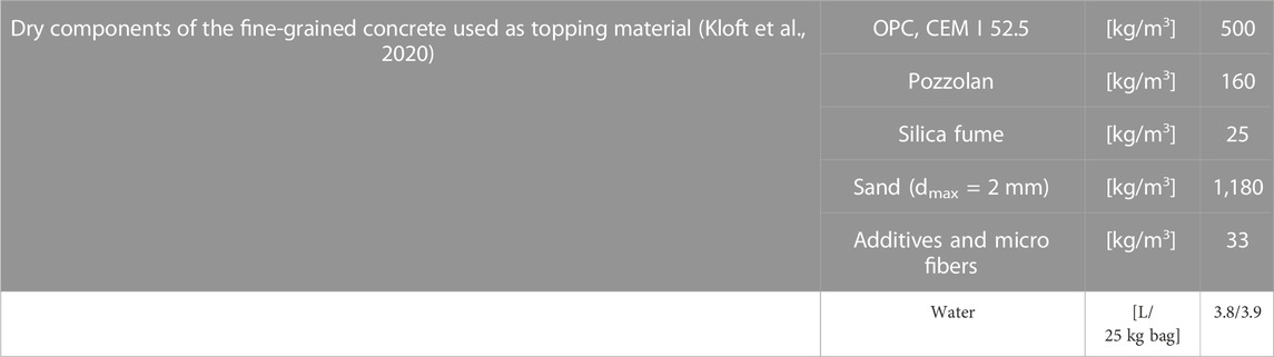
TABLE 1. Composition of the topping material.
For the lower, first applied topping layers, a stiffer material with a water content of 3.8 L per 25 kg of dry mix was used for a faster structural build-up and higher strength. For the upper, overlying topping layers, the water content was increased to 3.9 L/25 kg to reduce the materials’ yield stress and viscosity for easier surface finishing in the fresh-state smoothing process. The corresponding yield stresses and plastic viscosities were τ0,low = 186.2 Pa, ηpl,low = 55.1 Pa s and τ0,upp = 162.8 Pa, ηpl,upp = 47.1 Pa s for the lower and upper layer of topping material, respectively.
In order to be able to realize the locally varying component thicknesses resulting from the structure optimization, a path planning is required which enables a corresponding grading of the material application by adapting the speed. Those instructions are created in grasshopper starting as location and vector information for the robot to follow, being enhanced with speed information and commands for controlling the shotcrete process and lastly translated into G-Code. The processes to be executed in consequent order are: Stiffening coat spraying, Fiber Winding, SC3DP, surface finishing and edge milling.
To allow the fabric to maintain its desired shape, a thin layer of low-viscosity mortar is to be applied on the formwork. For this additive process, an even coating is to be applied with minimal loading of the structure. Here the self-weight of the material as well as the impact from the spraying process are being considered. For this a two-step process was designed where the bridge geometry was sprayed using two different paths, the first to spray the geometry where the epicenter of the spray follows the bending active beams, and the second following the fields between the beams. The paths are generated on the geometry after a remeshing step to create quadrangular faces, and are drawn through the centers of each quad face. To ensure even and complete coverage the distance of the spray nozzle to the geometry is calculated in accordance with the size of the face and the tool velocity is calculated based on the material flow versus the desired thickness on the area.
For an automated individualized reinforcement integration a novel robotic procedure has been established. It is builds up on the Dynamic Fiber Winding process (Hack et al., 2021), which has proven to be a versatile approach that allows for different robotic integration strategies tailored to the respective additive manufacturing technique such as SC3DP or Large Particle Bed 3D Concrete Printing (Mai et al., 2021; Gantner et al., 2022a). Based on a conceptual framework (Gantner et al., 2022b), the following method has been developed. A grid of 103 pins, which is attached to the bending-active beams and distributed evenly over the surface of the bridge, acts as anchorage for winding. Individual pin heights are derived from the optimized thickness distribution in order to align the reinforcement closely underneath the targeted top surface.
To achieve a precise matching between pin locations and the robot’s movement, the path planning workflow is enhanced by sensor feedback. The position and orientation of the pins, identified from a 3D-scan beforehand as described in Sec. 3.4, as well as the winding sequence serve as input for a parametric generation of the robotic winding path. Circle sectors (r = 50 mm) in an offset of 5 mm underneath the pinheads are formed to safely place the fibers while avoiding collisions. The decision whether to pass to the left or right of a pin, is taken automatically according to deflection angles between consecutive pins. Whenever the deflection is smaller than 5° the pins are passed in an alternating manner to avoid slipping from the pins.
The winding sequence encompasses two different layouts, one crosswise winding for bidirectional reinforcement coverage and an increased bending support in transversal direction, where each path was wound twice.
Similar to the stiffening coating of the textile formwork, the SC3DP process follows the geometry based on the quadrangular face centers of the regenerated mesh. Where this step differ from coating is the number of layers, the material, and the eventual applied thickness. The form finding and analysis methods have resulted in a shell geometry with varying thickness between 3 and 10 cm of concrete, which is to be applied in designated areas. Using this thickness map, together with the face area, the material flow, and material spray cone, the volume of material applied to an area per second can be defined. The robot tool velocity is then calculated in accordance with the thickness map, as visualized in Figure 5.
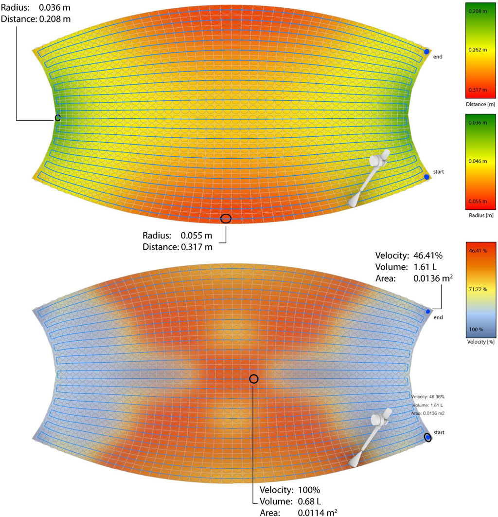
FIGURE 5. Print path generation with variance in spray distance and resulting cone radius to ensure full coverage of the shell geometry (above) and tool velocity map with consideration of spray distance/radius and desired shell thickness (Figure 4) considering a constant material flow (below).
Directly after the application of the fresh concrete the surface can be smoothed or structured using the 5-Axis CNC Mill. This post processing is possible when the concrete is still in green-state by distribution and smoothening to achieve the desired surface finish. The planned path for possible surface finishing was developed based on a custom spherical smoothing tool that rotates and needs to be applied in the concrete’s green state. It traces the tween curves, projected on the bridge geometry in longitudinal direction with a maximum distance of 80 mm in between. The individual curves were divided into an equal number of planes, oriented to align with the normal of the base surface of the bridge. Those planes were sorted in such a way that they represent alternating back and forth movements from the center of the surface to its edges to achieve well directed removal of excess material. An offset to the target surface is kept parametrically variable to be able to control the plunging depth into the material during the process based on desired pronunciation of the tween curves surface texture.
In contrast to preceding steps that were focused on the top surface, the sides of the bridge require a different processing strategy, as here, the concrete is inevitably encountered in a hardened state. To create a sharp edge on both sides of the pedestrian bridge, contour milling is performed as a last step in the fabrication chain. For this, a path is created out of a 3D scan that provides data of the actual geometry in order to minimize the required plunging depth and therefore time and energy consumption. The motion of the mill is dictated by a simple spline-curve along both sides of the bridge, touching the target surface of the planned geometry. For plunging depth control, a side-offset from the modeled rail surface was kept variable with a built-in limit to keep distance from the textile bottom and reinforcement inside.
Before carrying out the experiments for the automated concreting of the designed Bridge, the textile formwork was produced at the TU Delft using a Steiger VEGA T 3.130 CNC weft-knitting machine (Steiger Participations Sa, 2019) with a machine gauge of 10.2. The production process involved knitting four pieces, including two identical spear, each consisting of a double-layered/interlock knit design that incorporated channels for inserting the form giving rods. The dimensions of the knitted textiles were specific to the bridge design and resulted in a total length of 4.5 m and a width of 2.65 m in stretched condition. The total production time for the knitted formwork was approximately 2 hours of pure machine working time, with each piece taking about 1 h to complete. Thus, the entire production process for the two identical copies of knitted formwork required around 4 h in total. Due to its ultralight weight and packability, both textile formworks were able to be conventionally shipped in a medium sized parcel from TU Delft to TU Braunschweig, were it was later spanned into desired shape.
All further steps around the automated concreting of the textile formwork were taken out at the Digital Building Fabrication Laboratory (DBFL) located at the Institute for Structural Design (ITE) at TU Braunschweig.The DBFL is a robotic fabrication facility consisting of a CNC-gantry system with two independently controllable manipulators: a Stäubli TX 200 robot with six axes, which is mounted to a three axis gantries, and a five-axis Omag mill. The build space within the laboratory measures 10.5 × 5.25 × 2.5 m, enabling the production of large-scale structures through subtractive machining and additive manufacturing processes.
The robot was equipped with two different end effectors. The first is a shotcrete nozzle with a 12 mm diameter, utilizing a wet shotcrete spraying setup where concrete is supplied as ready-mix and is accelerated through the nozzle using pressurized air. The second end effector is a guiding device for applying continuous fiber reinforcement around pre-placed pins.
For the concrete setup, a 25-m concrete hose with a diameter of 50 mm was used, along with a modified “WM VarioJet FU” concrete pump modified for digital control input. Manual mixing of smaller batches was done with a “WM Jetmix 125″mixer, while an automated mixing plant by “Kniele” handled larger batches efficiently.
For the robotic reinforcement integration, the setup is supplemented by the Dynamic Winding Machine (DWM) (Hack et al., 2021). It fabricates continuous flexible fiber reinforcement on demand that consists of a primary roving impregnated by cold-curing epoxy resin and a helically wound secondary yarn, leading to improved bond properties (Rothe et al., 2023). Based on previous experience in terms of workability and performance (Gantner et al., 2022a), a 9,600 tex glass fiber roving, L-285 epoxy resin and a secondary glass fiber yarn of 300 tex were chosen.
Postprocessing of the fabricated components involved the use of end effectors integrated into the milling application. A stainless steel distribution plate with four trowels ensured even distribution of concrete. A custom-made spherical stainless steel surface finishing tool was employed to achieve the desired surface finish.
For the substructure of the bridge, two identical foundation blocks were casted, ensuring they were fully reinforced to withstand the forces applied during transportation, the self-weight of the structure, and the forces exerted by the bending active steel rods.
To enhance the stability and connection of the substructure, concrete anchors were utilized. These anchors provided a secure attachment point for the supportive steel frame. Additionally, ring nuts were incorporated into the design to facilitate the transportation process, ensuring the foundation blocks remained securely in place during transit.
Cartridges were embedded within the foundation blocks to hold the steel rods in position. These cartridges acted as receptacles for the rods, providing a stable and controlled environment for their placement. To ensure precise positioning of the cartridges, 3D printed holders were attached inside the mold, allowing for accurate alignment and placement of the steel rods within the substructure.
Through the implementation of reinforced foundation blocks, concrete anchors, rings nuts for transportation, and the utilization of cartridges with 3D printed holders, the substructure of the bridge was designed to provide structural stability, durability, and ease of assembly. These elements were crucial in ensuring the successful construction and long-term performance of the bridge.
A series of bending-active metal elements defined the geometry of the proposed pedestrian bridge. The next step was the integration of the 3D-knitted textile formwork. The process began by threading the metal rods through channels intrinsically designed into the fabric’s pattern. Once this was achieved, the rods were positioned in their predetermined locations.
Subsequently, efforts were made to adequately stretch the textile to cover the bridge’s planned geometry. By skipping a calibration step during the CNC-knitting process, the textiles could not initially be stretched into the desired shape. For this reason, a total of four pieces of textile formwork was used, instead of two, to cover half the length of the bridge, connect both sides in the middle and cut off the excess textile (Figure 6).
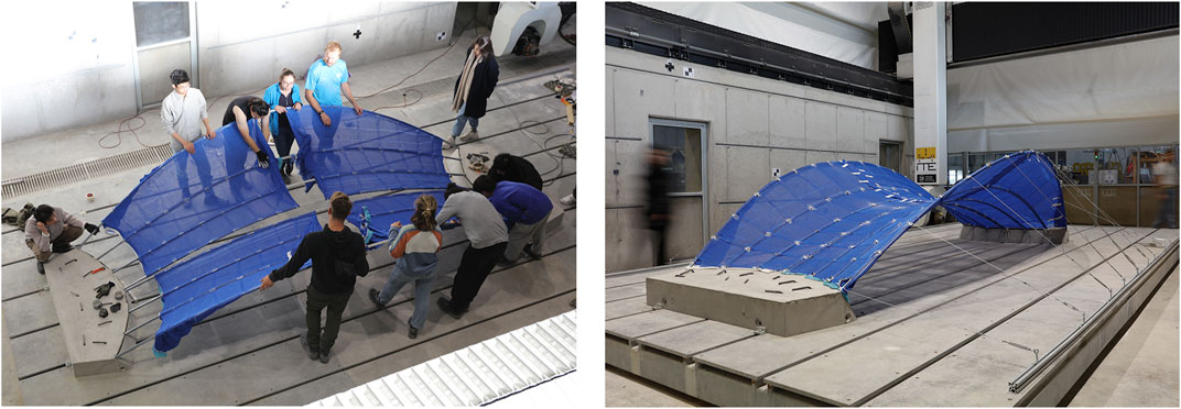
FIGURE 6. left: Spanning of textile formwork with students, right: Assembled substructure with formwork.
In the multi-step fabrication process of the bridge, it was essential to conduct quality inspections after each step, involving a digital comparison between the as-built and as-planned geometry. To achieve this, Terrestrial Laser Scanner (TLS) measurements were utilized to represent the current geometry of the fabricated structure. Detailed information about the automatic registration of the digital model with the TLS data can be found in the work by (Mawas, Maboudi, and Gerke, 2022a). To monitor the progress and ensure that the printed object corresponds with the design, various distance methods were employed (Mawas, Maboudi, and Gerke, 2022b). Cloud-to-Cloud (C2C) algorithms were specifically used in this case to assess the progress between different printing steps. Additionally, accurately detecting the exact positions of the steel pins used for reinforcement winding was of utmost importance.
One approach involved using the point cloud data obtained after the pins’ installation. A constructive Octree was implemented, consisting of 21 levels, and only data up to the 10th level was retained. By manually segmenting a few entities from two subgroups within the subsampled point cloud, a supervised classifier was trained using the algorithm proposed by (Brodu and Lague, 2012). The classifier’s datasets categorized points into two classes: pins (blue) and non-pins, which represented the background (red), as depicted in Figure 7. C2C comparison was performed on these classified datasets. Points that were misclassified (false positives) displayed a small distance from the bridge body, while true pins exhibited a more significant distance. By applying thresholding to the C2C result, false positives could be distinguished from true positives. However, further refinement of the approach was necessary, as it led to the detection of 108 different labels through an auto labelling algorithm, while there should have been only 103 pins. Moreover, some of the detected pins still contained noise and erroneous classification.
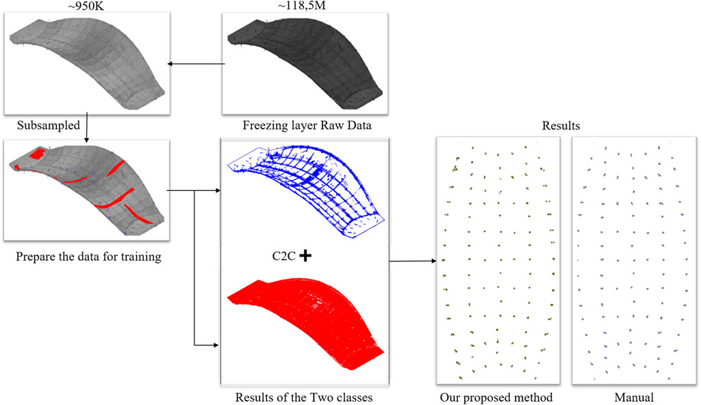
FIGURE 7. Overview of the automated pin extraction process.
Despite the need for improvements, it was evident from the analyzed data that this semi-automated approach had significant potential compared to manual methods. Overall, this methodology presented a practical and effective solution for monitoring the digital fabrication process and accurately detecting the pins’ locations.
Once the geometry and location had been accurately captured with the 3D scanner, the scan data was transferred to the computer-aided design software Rhinoceros 3D. Subsequently a path planning for a first coating with cement paste was automatically generated. Based on preliminary parameter studies a path width of 40 cm with a layer height of 1–2 mm was found to be optimal. To achieve the planned Layer geometry a feed rate of 9,600 mm/min at a nozzle distance of 1,100 mm was chosen for the robotic parameters, and a smallest possible concrete flow rate of <0.4 m³/h was combined with an air flow rate of 30 Nm³/h for shotcrete parameters. Applied to the path planning and executed 2 times with cement paste resulted in a thin, even coating of cement paste of around 3 mm thickness (Figure 8). Both layers were applied in 9 min of time.
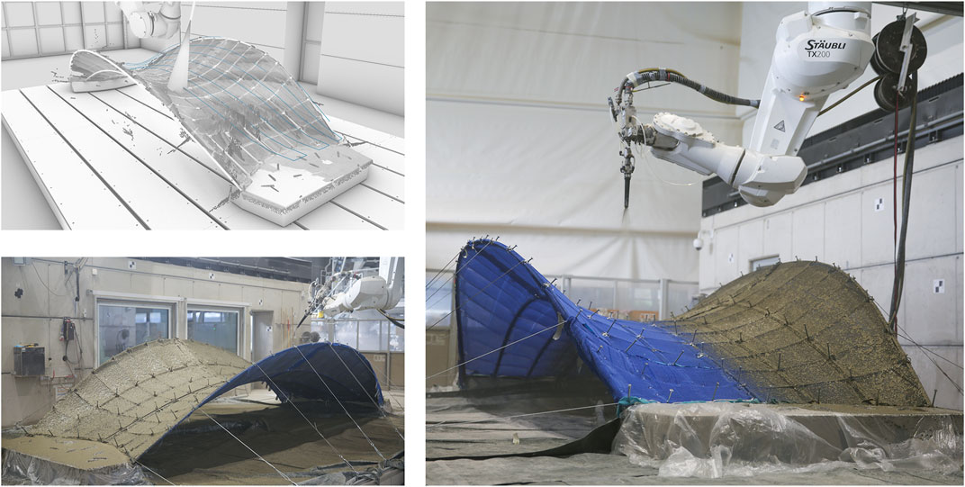
FIGURE 8. top left: Robotic path, bottom left: Fully covered textile formwork, right: robotic spraying of cement paste as a stiffening coat.
It was observed that the relatively liquid cement paste penetrated the knit and formed droplets on the bottom of the structure, evenly distributed but only at the single layered fabric areas. Furthermore, a slightly pronounced sagging behavior with a depth of 5–15 mm, depending on the patch size, was caused by the weight of the applied coating. This state was stiffened by its curing, so that no further sagging occurred during the application of the subsequent layers of concrete.
Prior to the robotic spraying of concrete onto the stiffened textile formwork, continuous glass fiber reinforcement was applied by means of robotic winding. The following steps were undertaken during this process:
As part of the aforementioned setup the DWM was prepared and positioned stationary in the workspace. The robot arm was equipped with the winding end-effector through which the reinforcement strand coming from the DWM could be fed and fixed to an initial pin on the bridge. From there, the robot systematically wound the reinforcement along the pins according to the path described in Section 2.2.4.
The continuous reinforcement generation is adjusting to the pull-out speed in a certain range, so that the end-effector speed was limited to 35 mm/s. The overall winding time for 95 m of reinforcement was 110 min. There were interruptions due to secondary yarn breaking off. The problem was solved temporarily by switching to a cotton yarn. Through inspection of the glass fiber yarn spool, it was found that it was coiled too loosely, which led to excessive friction in unrolling.
As the robot path was based on 3D-scanned pin locations, the fibers were placed accurately without collisions. However, the concave curvature in transversal direction partly led to slipping from the pins. In these cases, the strand could be pushed back in place manually, but it became evident that the selected pan-head screws, representing the pins, were not ideally suited for such curvatures. After the robotic reinforcement integration (Figure 9), the epoxy resin needed 24 h of curing before the subsequent SC3DP application.
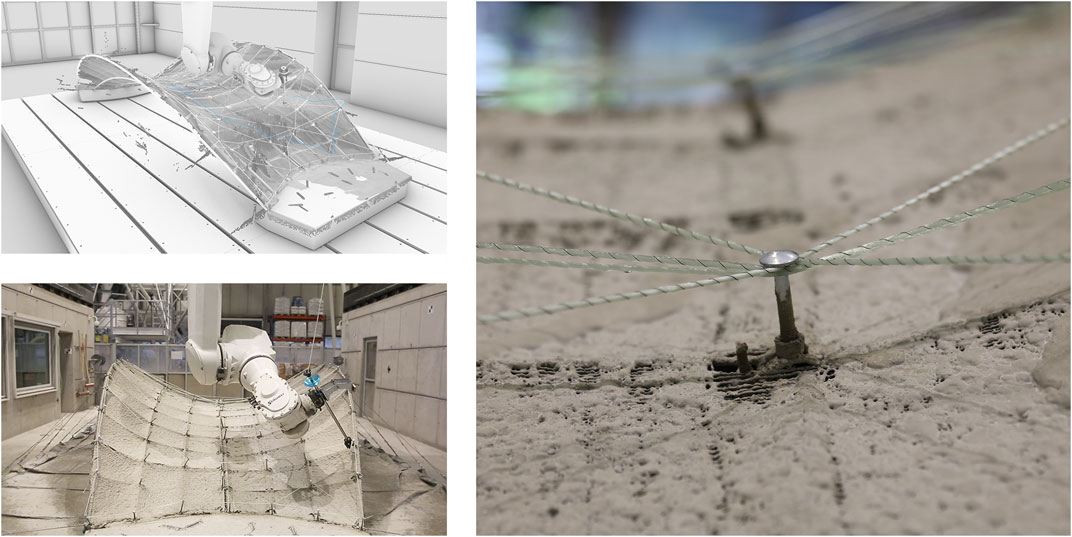
FIGURE 9. top left: Robotic path, bottom left: Dynamic fiber winding process, right: Detail of reinforcement knot around pin.
Succeeding the integration of fiber reinforcement, the load bearing layer of fine grain concrete is applied. The SC3DP process is repeated layer by layer onto the stiffened geometry and structurally embed the fiber reinforcement.
Throughout the underlying geometry, the thickness of the desired concrete layer ranges from 3–10 cm, thus certain adjustments in the path planning for the structural layer are required first. As described in Section 2.2.4, the path planning is adjusted by differentiating the traverse speed during the spraying process, to realize a varying layer thickness according to the thickness map. The following parameters were used during the material application.
• Feed rate: 3,000–9,000 mm/min
• Nozzle distance: 500 mm
• Concrete volume flow: 0.4 m³/h
• Air volume flow: 40 Nm³/h
Starting on one corner of the bridge structure, the path for material application follows the longest edge of the bridge and moves inward to the other edge subsequently with a spacing of 1.5 times the diameter of the spray cone. This path is repeated from the other side with an offset of the same spacing as before to fill the gaps between the previous layers and to achieve an overlap of strands for an even material distribution and uniform layer build-up. Thereby the material is sprayed from a distance of 500 mm to also assure a sufficient cover of the fiber reinforcement. Using a higher distance, thus a wider spray cone, the mortar covers the fibers evenly without creating any spray shadows or voids.
While spraying, the nozzle was always oriented perpendicular to the surface to ensure a consistent material distribution on the differently angled surface. The layer-wise material application was repeated until a sufficient cover of the reinforcement was ensured. In this case approx. 15 layers of fine grain concrete were sprayed to cover the reinforcement and manufacture the shell structure in the variable thickness (Figure 10). Finally, another layer was applied just on the edges of the structure. This layer was applied to cover protruding pins and to adjust the thickness of the edge.
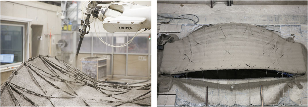
FIGURE 10. left: Robotic shotcrete process, right: Surface quality after shotcrete.
During the process, certain deviations from the desired material build-up were observed. Firstly, the pins and the fiber strands were not embedded evenly into the concrete. Evidently, the initially sparse elevations have intensified due to the multiple spray passes instead of being leveled out in the surrounding concrete. Furthermore, an increased material deposition in the transition area from shell to foundation was found, as robot speed limits for repositioning were reached in these specific locations.
After the application, the bridge was covered to harden for 28 days before applying the cover layer for an architectural surface on top.
During the fabrication process, the need to level the uneven shotcrete surface of the previous fabrication steps became apparent. Consequently, a process of collaborative machining was devised, which entailed applying a stable and consistent layer thickness to the surface while redistributing it in its fresh state using the mill of DBFL.
To begin, precise 3D scanning data was utilized to accurately position and measure surface imperfections. The initial base surface was then repositioned and manipulated in Rhinoceros 3D to create a new target surface. The objective was to achieve a symmetrical surface that closely matched the base surface without any overlap. On average, a deviation of 4 cm was observed, ranging from a minimum of 0.1 cm to a maximum of 7 cm.
With knowledge of the average deviation, the plan involved adding four layers of 1 cm thickness each through SC3DP. The excess material from the high points of the uneven base surface would be redistributed to fill the lows using the mill. In order to distribute the concrete at a state of minimal viscosity, both the shotcrete application and material distribution were executed simultaneously, letting the mill follow the robot as closely as possible. For both process steps, a meandering path in the transversal direction, normal to the target surface, was chosen. Previous experiments had shown that spraying wide, overlapping paths helped to even out the lows between paths. Thus, a nozzle distance of 60 cm was combined with a feed rate of 4,500 mm/min to achieve a layer width of 30 cm and a minimum layer thickness of 1 cm. The layer thickness was increased at the overlaps between the meandering paths, with a path distance of 20 cm.
For the application and spreading of the leveling course, a path planning was chosen in which the spraying robot applies the material crosswise from right to left and the second gantry follows at a distance of 1.5 m (Figure 11).
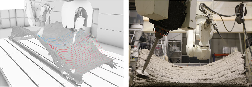
FIGURE 11. left: Robotic path, right: Collaborative process of surface leveling.
The distribution path followed similar principles, but the parameters were adjusted to account for the meandering path’s distance and the radius of the distribution tool (10 cm). As a result, a faster feed rate of approximately 9,000 mm/min was necessary to keep up with the shotcrete robot. To ensure the material was carried in front, the mill’s angle was tilted by 5° in the process direction. A spindle speed of 450 rounds/min was sufficient for distributing the wet concrete without throwing it in an uncontrolled manner.
Directly after the surface leveling, the distribution tool was switched to a spherical surface structuring tool with a diameter of 20 cm. It was custom-built for the planned surface texture out of a 3D printed base that holds a spherical stainless steel shield. An additional device was attached at the mill’s base to clean the shield from fresh concrete sticking to it during the smoothening process. With this new tool geometry, parameters for plunging depth, tween distance and direction were tested and simulated for architectural design reasons. It was chosen a longitudinal tween path for the surface finishing with a tween distance of 8 cm in the middle widest part of the bridge. The immersion depth was kept variable, to react to the actual behavior in the process, which ended up at a minimum immersion depth of 4 mm.
Due to the certain path planning of the mill from the inside to the outside on the surface, the fresh concrete could be transported to the outside, away from the finished surface, towards the unfinished parts. The tool component for cleaning the trowel surface thereby functioned as a transporter of the excess material. The rubber lip on the cleaner collected the excess material and, by its orientation, always dropped it on the path yet to be processed (Figure 12).
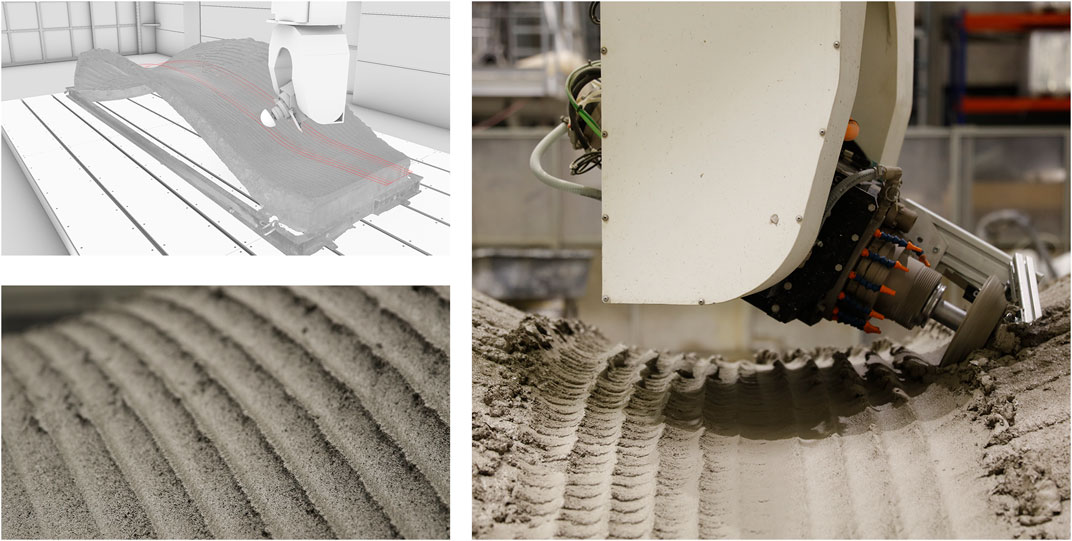
FIGURE 12. top left: Robotic path, left bottom: Surface quality after finishing, right: Surface finishing process with spherical smoothing tool.
The surface quality increased with each repetition of the smoothing process. However, the constant force of the curing concrete on the stainless steel sphere caused it to deform after the second pass and to ovulate in the last pass. This ovulation resulted in regular irregularities of about 1 mm in height with each rotation of the tool, that is, about every 2 cm on each track.
The last step was to define a path milling the concrete edges of the bridge with a customized side cutting milling drum in order to create a defined silhouette. Due to the requirements of the contour milling process using a milling drum, the milling path had to be defined from above the bridge facing down to it (Figure 13). It was decided to tilt the mill dynamically between the foundations and the middle area in a range of 5°–60° from vertical. The maximum tilt was defined from 3D scan to remove maximum of undefined, rough concrete and the minimum was defined to prevent the non-cutting front side of the tool from diving into concrete.
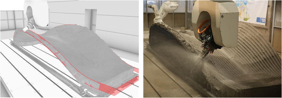
FIGURE 13. left: Milling path, right: Contour milling in process.
Due to the rather coarse dissolution process of shotcrete spraying and the many working steps, it became visible after the first milling pass that there were still a few voids in the edge area of the bridge, not deeper than 2 cm. These holes were filled with the same concrete in an additional manual step. After 24 h, it was milled again. In this last step of the production process, about 2 mm of material was removed to achieve the final surface quality.
The goal of this research, which was to combine 3D knitted formwork and robotic shotcrete spraying, and move towards full automation of the KnitCrete manufacturing method, has been successfully achieved.
During the experimentation process, imperfections in the SC3DP of the structural layer were encountered, resulting in uneven surface and deviations from the as-planned design. However, this led to the development of an additional manufacturing technique for surface leveling. This technique has been proven to effectively even out inaccuracies in surfaces, improving the overall quality of the structure. The use of multi-material robotic shotcrete spraying has proven to be beneficial in various process steps. By employing different materials for specific purposes, such as applying a light stiffening coat layer and later adding structural mass with concrete, the fabrication process becomes more versatile and tailored to the requirements of the project.
The positive form-giving factors of formwork in general were preserved while significantly reducing the formwork mass through the use of CNC knitted stay-in-place formwork. This reduction in mass not only reduces costs but also minimizes waste generated during the construction process. Another notable achievement of this research is the significant reduction in manual labor involved in the concreting process of the knitted formwork. The combination of CNC knitting technology and robotic shotcrete spraying has virtually eliminated the need for manual labor, making the process more efficient and less labor-intensive.
Overall, after the leveling of the imperfections described before, the as-build geometry of the bridge closely matched its as-planned geometry due to the hybrid manufacturing approach that combines both additive and subtractive manufacturing methods (Figure 14). This demonstrates the high degree of accuracy and fidelity achieved through this fabrication process.
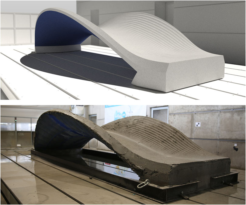
FIGURE 14. top: Rendered vision of the pedestrian bridge, bottom: Final demonstrator after fabrication at the DBFL.
In terms of fabrication design, there are several potential improvements that can be considered. Firstly, during the stiffening coat spraying process, it is suggested to apply only one layer initially. This approach aims to minimize any sagging of the textile formwork. After the first layer has stiffened, another layer can be added to fully close the textile, ensuring a more precise and uniform surface.
Another improvement pertains to the sequence of construction steps. It is recommended to first build the shotcrete mass and then add the wound fiber reinforcement afterwards. This adjustment can help prevent spray shadows, particularly under the reinforcement and at the pins, resulting in a more even distribution of materials and enhanced structural integrity.
Additionally, changes in path planning can contribute to refining the fabrication process. It is important to avoid abrupt robotic repositioning and speed changes, as these can introduce inconsistencies and irregularities in the printed structure. By focusing on smoother movements and transitions, the overall quality of the fabricated elements can be improved. Upgrading the speed control in the path planning script would be also beneficial. This enhancement would allow for modulation of the speed based on the changing nozzle distance during the robotic spraying process. This dynamic control can contribute to better accuracy and efficiency, resulting in a more precise and reliable fabrication process.
By implementing these suggested improvements, the fabrication method combining KnitCrete formwork and robotic shotcrete spraying can be further optimized, leading to enhanced structural quality, increased efficiency, and improved surface finish. After all, it is assumed that after optimizing the shotcrete path planning and process sequence, a thin and efficient concrete shell with an optimized thickness profile can be fabricated. This will contribute to the advancement of digital concrete construction techniques and pave the way for more sophisticated and efficient additive manufacturing methods in the future.
In conclusion, this research successfully combines 3D knitted formwork and robotic shotcrete spraying, progressing towards full automation of the KnitCrete manufacturing method. The outcome of this interdisciplinary endeavor, represented by a one-to-one demonstrator in the form of a pedestrian bridge, has achieved several significant milestones and contributions:
Seamless Integration of Advanced Technologies: The project brought together a range of cutting-edge technologies, including 3D knitted formwork, robotic shotcrete, dynamic fiber reinforcement, laser scanning, CNC green-state post-processing, and CNC milling, demonstrating their successful integration into a single fabrication process.
Innovative Surface Leveling Method: The challenges of deviating layer thickness encountered in the Shotcrete 3D Printing (SC3DP) of the layer of structural mass led to the development of an innovative surface leveling technique. This technique effectively rectifies surface irregularities, enhancing the overall structural quality.
Versatility through Multi-Material Robotic Shotcrete: The use of multi-material spray robots proved valuable as they offer great versatility by using different materials for specific purposes. This included the application of a light stiffening coating of cement paste and the subsequent placement of structural mass with concrete, which was precisely tailored to the project requirements.
Sustainable Construction through Reduced Formwork Mass: By adopting 3D knitted stay-in-place formwork, the research preserved the advantages of formwork while significantly reducing its mass. This reduction not only yielded cost savings but also contributed to minimizing waste generated during the construction process.
Significant Reduction in Manual Labor: A notable achievement was the substantial reduction in manual labor traditionally associated with the concreting of knitted formwork. The seamless integration of CNC knitting technology and robotic shotcrete spraying effectively eliminated the need for manual labor, streamlining the process and reducing labor intensity.
Robotic Precision in the Concreting Process: Although there is still some future work to fine tune the SC3DP path generation with variable thickness, the as-built geometry of the final bridge closely mirrors the geometry planned for refinement, underscoring the exceptional precision and fidelity achieved through this fabrication process.
This research represents a significant advance in additive manufacturing and offers the potential to transform the manufacturing of geometrically complex, material-efficient architectural elements. The seamless integration of multiple cutting-edge technologies underscores the value of interdisciplinary collaboration, innovation and precision. It is anticipated that this groundbreaking work will serve as a source of inspiration for future developments and innovations in construction and digital fabrication, promoting sustainability, efficiency, and versatility in building practice.
The raw data supporting the conclusion of this article will be made available by the authors, without undue reservation.
PR: Data curation, Formal Analysis, Investigation, Methodology, Project administration, Software, Visualization, Writing–original draft. SG: Writing–original draft, Data curation, Investigation, Methodology, Project administration, Software. GD: Data curation, Investigation, Methodology, Software, Validation, Writing–original draft. LB: Data curation, Investigation, Methodology, Software, Validation, Visualization, Writing–original draft. NC: Data curation, Investigation, Methodology, Software, Validation, Visualization, Writing–original draft. RD: Data curation, Investigation, Writing–original draft. MH: Investigation, Validation, Writing–review and editing. IM: Investigation, Validation, Writing–original draft. KM: Investigation, Methodology, Software, Validation, Visualization, Writing–original draft. DL: Resources, Writing–review and editing. PD’A: Conceptualization, Methodology, Project administration, Resources, Software, Supervision, Visualization, Writing–review and editing. KD: Conceptualization, Funding acquisition, Methodology, Project administration, Supervision, Writing–review and editing. NH: Conceptualization, Funding acquisition, Investigation, Methodology, Project administration, Resources, Supervision, Writing–review and editing. MP: Conceptualization, Methodology, Project administration, Resources, Software, Supervision, Visualization, Writing–review and editing.
The author(s) declare financial support was received for the research, authorship, and/or publication of this article. The Authors gratefully acknowledge the German Research Foundation (DFG), for funding the collaborative research center TRR 277—Additive Manufacturing in Construction (Subprojects A04, A05, B05, C02 and C06) and the DFG Large Research Equipment, Digital Building Fabrication Laboratory (project numbers 416601133 and 414265976). We acknowledge support by the Open Access Publication Funds of Technische Universität Braunschweig. PR gratefully acknowledges Holcim Innovation Center for funding his research work.
The following students of the “Computational Design and Fabrication” seminar are acknowledged for their contribution to the demonstrator, digital simulations, design and construction, and project documentation: A. Kariouh, C. Zhou, E. Pestriakova, F. Chovghi, F. Wang, H. Liu, J. Sukhowerchov, N. Kovacs, P. Götz, R. Li, R. Pekuss, T. Schlinker, T. Sun, S. Pagés I Diaz, R. San Miguel. We also acknowledge DBFL’s technician team; Benedict Sonntag and Mareike Krake, for their support during fabrication.
The authors declare that the research was conducted in the absence of any commercial or financial relationships that could be construed as a potential conflict of interest.
The handling editor VL declared a past co-authorship with the authors NH and RD.
All claims expressed in this article are solely those of the authors and do not necessarily represent those of their affiliated organizations, or those of the publisher, the editors and the reviewers. Any product that may be evaluated in this article, or claim that may be made by its manufacturer, is not guaranteed or endorsed by the publisher.
Boulic, L., D’Acunto, P., Bertagna, F., and Juan José, C. (2020). Form-driven design of a bending-active tensile façade system. Int. J. Space Struct. 35 (4), 174–190. doi:10.1177/0956059920931021
Brodu, N., and Lague, D. (2012). 3D terrestrial LiDAR data classification of complex natural scenes using a multi-scale dimensionality criterion: applications in geomorphology. ISPRS J. Photogrammetry Remote Sens. 68 (June), 121–134. doi:10.1016/j.isprsjprs.2012.01.006
Brucker, J., Belinda, M. G., and Marenjak, S. (2021). Review of the construction labour demand and shortages in the EU. Buildings 11 (1), 17. doi:10.3390/buildings11010017
Buswell, R. A., Leal da Silva, W. R., Bos, F. P., Schipper, H. R., Lowke, D., Hack, N., et al. (2020). A process classification framework for defining and describing digital fabrication with concrete. Cem. Concr. Res. 134 (August), 106068. doi:10.1016/j.cemconres.2020.106068
Cao, T., D’Acunto, P., Juan José, C., Alessandro Tellini, T., Schwartz, J., and Zhang, H. (2021). Design of prestressed gridshells as smooth poly-hypar surface structures. Structures 30 (April), 973–984. doi:10.1016/J.ISTRUC.2021.01.047
Chudley, R., and Greeno., R. (2006). Advanced construction technology. Harlow: Pearson Education, 632. Available at: https://books.google.com/books?id=rwC_tUX-GxYC&pgis=1.
D’Acunto, P., Jasienski, J. P., Ole Ohlbrock, P., Fivet, C., Schwartz, J., and Zastavni, D. (2019). Vector-based 3D graphic statics: a framework for the design of spatial structures based on the relation between form and forces. Int. J. Solids Struct. 167 (August), 58–70. doi:10.1016/J.IJSOLSTR.2019.02.008
Dressler, I., Freund, N., and Lowke, D. (2020). “Control of strand properties produced with shotcrete 3D printing by accelerator dosage and process parameters,” in Second RILEM International Conference on Concrete and Digital Fabrication, 42–52. doi:10.1007/978-3-030-49916-7_5
Estellé, P., Lanos, C., Perrot, A., and Amziane, S. (2008). Processing the vane shear flow data from Couette analogy. Appl. Rheol. 18 (3), 34037-1–34037-6. doi:10.1515/arh-2008-0009
Freund, N, and Lowke, D. (2022). “Interlayer Reinforcement in Shotcrete-3D-Printing: The Effect of Accelerator Dosage on the Resulting Bond Behavior of Integrated Reinforcement Bars,” in Open Conference Proceedings, 83–95. doi:10.52825/ocp.v1i.72
Gantner, S., Rennen, P., Tom, R., Hühne, C., and Hack, N. (2022a). “Core winding: force-flow oriented fibre reinforcement in additive manufacturing with concrete,” in Third RILEM International Conference on Concrete and Digital Fabrication, 391–396. doi:10.1007/978-3-031-06116-5_58
Gantner, S., Tom-Niklas, R., Hühne, C., and Hack, N. (2022b). Reinforcement strategies for additive manufacturing in construction based on dynamic fibre winding: concepts and initial case studies. Open Conf. Proc. 1 (February), 45–59. doi:10.52825/ocp.v1i.78
Gramazio, F., and Kohler, M. (2013). “The robotic touch: how robots change architecture: gramazio,” no. 16: 8–10. Available at: http://cataleg.upc.edu/record=b1439396∼S1*cat.
Greco, C. (2008). Pier luigi nervi. Von den ersten patenten bis zur ausstellunghalle in turin 1917–1948. Available at: https://art.torvergata.it/handle/2108/32297.
Hack, N., Bahar, M., Hühne, C., Lopez, W., Gantner, S., Khader, N., et al. (2021). Development of a robot-based multi-directional dynamic fiber winding process for additive manufacturing using shotcrete 3D printing. Fibers 9 (6), 39. doi:10.3390/fib9060039
Hack, N., and Kloft, H. (2020). “Shotcrete 3D printing technology for the fabrication of slender fully reinforced freeform concrete elements with high surface quality: a real-scale demonstrator,” in Second RILEM International Conference on Concrete and Digital Fabrication, 1128–1137. doi:10.1007/978-3-030-49916-7_107
Hawkins, W. J., Michael, H., Ibell, T. J., Kromoser, B., Alexander, M., Orr, J. J., et al. (2016). Flexible formwork technologies – a state of the art review. Struct. Concr. 17 (6), 911–935. doi:10.1002/suco.201600117
Kloft, H., Hack, N., Mainka, J., Leon, B., Herrmann, E., Ledderose, L., et al. (2019). Additive fertigung im bauwesen: erste 3-D-gedruckte und bewehrte betonbauteile im shotcrete-3-D-printing-verfahren (SC3DP). Bautechnik 96 (12): 929–938. doi:10.1002/bate.201900094
Kloft, H., Krauss, H.-W., Hack, N., Herrmann, E., Neudecker, S., Varady, P., et al. 2020. Influence of process parameters on the interlayer bond strength of concrete elements additive manufactured by shotcrete 3D printing (SC3DP). Cement and concrete research 134. doi:10.1016/j.cemconres.2020.106078
Koehler, E. P., and Fowler, D. W. (2014). Development of a portable rheometer for fresh Portland cement concrete. Texas: Austin. doi:10.15781/T2X539
Konstantatou, M., D’Acunto, P., and Allan, M. (2018). Polarities in structural analysis and design: N-dimensional graphic statics and structural transformations. Int. J. Solids Struct. 152 (November), 272–293. doi:10.1016/J.IJSOLSTR.2018.07.003
Kovári, K. (2003). History of the sprayed concrete lining method—Part II: milestones up to the 1960s. Tunn. Undergr. Space Technol. 18 (1), 71–83. doi:10.1016/S0886-7798(03)00006-3
Lachmayer, L., Böhler, D., Freund, N., Mai, I., Lowke, D., and Raatz, A. (2023). Modelling the influence of material and process parameters on shotcrete 3D printed strands - cross-section adjustment for automatic robotic manufacturing. Automation Constr. 145 (January), 104626. doi:10.1016/j.autcon.2022.104626
Leslie, T. (2017). Beauty’s rigor: patterns of production in the work of pier luigi nervi. University of Illinois Press. doi:10.5406/j.ctt1vw0s2n
Liddell, I. (2015). Frei Otto and the development of gridshells. Case Stud. Struct. Eng. 4 (August), 39–49. doi:10.1016/j.csse.2015.08.001
Lu, Z., Haist, M., Ivanov, D., Jakob, C., Jansen, D., Leinitz, S., et al. (2019). Characterization data of reference cement CEM I 42.5 R used for priority program DFG SPP 2005 ‘opus fluidum futurum - rheology of reactive, multiscale, multiphase construction materials. Data Brief 27 (October), 104699. doi:10.1016/j.dib.2019.104699
Lugowski (2013). Ferrocement super-insulated shell house design and construction. Available at: http://oatd.org/oatd/record?record=oai%5C%3ADiVA.org%5C%3Akth-124209.
Mai, I., Leon, B., Freund, N., Gantner, S., Kloft, H., Lowke, D., et al. (2021). Large Particle 3D concrete printing—a green and viable solution. Materials 14 (20), 6125. doi:10.3390/ma14206125
Mawas, K., Maboudi, M., and Gerke, M. (2022a). Direct Co-registration of as-built and as-designed data in digital fabrication.
Mawas, K., Maboudi, M., and Gerke, M. (2022b). AUTOMATIC GEOMETRIC INSPECTION IN DIGITAL FABRICATION. Int. Archives Photogrammetry, Remote Sens. Spatial Inf. Sci. XLIII-B1-2022, 459–466. (May): 459–66. doi:10.5194/isprs-archives-XLIII-B1-2022-459-2022
Oberbichler, T. (2019). EQlib. Available at: https://github.com/oberbichler/EQlib.
Otto, F. (1975). Multihalle Mannheim. Mannheim Available at: Https://Www.Bauwelt.de/Themen/Bauten/Frei-Otto-Multihalle-Mannheim-2845677.Html.
Pellegrino, M., Sardone, L., Rosso, M. M., Gozzi, V., and Chiaia, B. (2024). Algorithm-aided design and analysis for the comparative models study of heinz islers shells in Shell and spatial structures. Amedeo manuello bertetto, francesco marmo, and andrea micheletti, 512–21. Editor S. Gabriele (Cham: Springer Nature Switzerland).
Popescu, M. A. (2019). KnitCrete: stay-in-place knitted formworks for complex concrete structures (issue 26063). Zurich: ETH Zurich. doi:10.3929/ethz-b-000408640
Popescu, M., Reiter, L., Liew, A., Van Mele, T., Flatt, R. J., and Block, P. (2018b). Building in concrete with an ultra-lightweight knitted stay-in-place formwork: prototype of a concrete shell bridge. Structures 14, 322–332. doi:10.1016/j.istruc.2018.03.001
Popescu, M., Rippmann, M., Liew, A., Reiter, L., Flatt, R. J., Van Mele, T., et al. (2021). Structural design, digital fabrication and construction of the cable-net and knitted formwork of the KnitCandela concrete shell. Structures 31 (June), 1287–1299. doi:10.1016/J.ISTRUC.2020.02.013
Popescu, M., Rippmann, M., Van Mele, T., and Block, P. (2018a). Automated generation of knit patterns for non-developable surfaces, Humanizing digital reality, 271–84. Singapore: Springer Singapore. doi:10.1007/978-981-10-6611-5_24
Rennen, P., Khader, N., Hack, N., and Kloft, H. (2021). “A hybrid additive manufacturing approach,” in Acadia 2021: realignments: toward critical computation, 428–437.
Rothe, T., Gantner, S., Hack, N., and Hühne, C. (2023). Optimization of tensile properties and bond behaviour to concrete of fibre reinforcement strands produced within a dynamic fibre winding process. doi:10.5281/zenodo.8133237
Saleh, H. S. A. (1987). “Computer aided design of shell structures,” in Shell and spatial structures: computational aspects. Editors G. A. S. Q. De Roeck, M. Van Laethem, and E. Backx (Berlin, Heidelberg: Springer Berlin Heidelberg), 29–37.
Steiger Participations Sa (2019). Vega 3.130, Available at: Https://Steiger-Textil.Ch/Project/Vega3130/.
Thomsen, M., and Hicks, T. (2008). To knit a wall, knit as matrix for composite materials for architecture.
Toyo Ito and Associates (2014). Taichung.Taichung metropolitan opera house. Available at: Https://Www.Architecturalrecord.Com/Articles/12040-National-Taichung-Theater-by-Toyo-Ito-Associates.
TRR 277 - Additive Manufacturing in Construction (AMC) TRR277 (2023). TRR 277 - additive manufacturing in construction (AMC) TRR277. Available at: https://amc-trr277.de/(Accessed November 7, 2023).
Keywords: additive manufacturing in construction, shotcrete 3D printing, stay-in-place formwork, knitcrete, flexible formwork, robotic fiber winding, green-state post-processing, digital fabrication
Citation: Rennen P, Gantner S, Dielemans G, Bleker L, Christidi N, Dörrie R, Hojjat M, Mai I, Mawas K, Lowke D, D’Acunto P, Dörfler K, Hack N and Popescu M (2023) Robotic knitcrete: computational design and fabrication of a pedestrian bridge using robotic shotcrete on a 3D-Knitted formwork. Front. Built Environ. 9:1269000. doi: 10.3389/fbuil.2023.1269000
Received: 28 July 2023; Accepted: 13 November 2023;
Published: 07 December 2023.
Edited by:
Vittoria Laghi, University of Bologna, ItalyReviewed by:
Lidiana Arrè, University of Bologna, ItalyCopyright © 2023 Rennen, Gantner, Dielemans, Bleker, Christidi, Dörrie, Hojjat, Mai, Mawas, Lowke, D’Acunto, Dörfler, Hack and Popescu. This is an open-access article distributed under the terms of the Creative Commons Attribution License (CC BY). The use, distribution or reproduction in other forums is permitted, provided the original author(s) and the copyright owner(s) are credited and that the original publication in this journal is cited, in accordance with accepted academic practice. No use, distribution or reproduction is permitted which does not comply with these terms.
*Correspondence: Philipp Rennen, cC5yZW5uZW5AdHUtYnJhdW5zY2h3ZWlnLmRl
Disclaimer: All claims expressed in this article are solely those of the authors and do not necessarily represent those of their affiliated organizations, or those of the publisher, the editors and the reviewers. Any product that may be evaluated in this article or claim that may be made by its manufacturer is not guaranteed or endorsed by the publisher.
Research integrity at Frontiers
Learn more about the work of our research integrity team to safeguard the quality of each article we publish.