 Mostafa Ali Taha Ali Okasha
 Mohamed Abdel Razek1
 Soliman Alkhatib
- 1Faculty of Engineering Al-Azhar University, Cairo, Egypt
- 2Engineering Mathematics and Physics Department, Future University in Egypt, Cairo, Egypt
The development of composite sections is of great importance in structural design, with the aim of reducing weight and deflection while limiting the effect on the composite section’s strength and durability. This paper examines the computational analysis of composite sections where reinforced concrete was replaced with autoclaved aerated concrete (AAC) in the compression zone. The first principles of concrete combined with Hook’s law were adopted to find a flexure, shear, equivalent modulus of elasticity, effective moment of inertia, and deflection. The results are discussed and investigated using the finite element models developed by ANSYS WORKBENCH software. We found that the proposed analytical model can effectively provide a solution for the composite cross-section. The comparison between the theoretical calculation of the first cracking loads and the finite element percentage ranges from 89 to 110%. The ratio of the computational calculation of the modulus of elasticity to the finite element results ranged from 0.91 to 1.06. The comparison between the theoretical calculation of the effective moment of inertia to the finite element percentage ranged from 92% to 118%. The ratio of the computational calculation deflection to the finite element ranged from 0.87 to 1.15.
Introduction
Autoclaved aerated concrete (AAC) is a low-density cementitious product of calcium silicate hydrate as a form of cellular concrete. The low density is obtained by forming microscopic air bubbles, which mainly occurs by chemical reactions during the liquid or plastic phase. These air bubbles are uniformly distributed and retained in the matrix during the setting, hardening, and subsequent curing with high-pressure steam in an autoclave to produce a homogeneous structure with microscopic void cells. AAC was first commercially produced in Sweden in 1923. Since then, its production and use have globally spread to more than 40 countries including North America, Central and South America, Europe, the Middle East, the Far East, and Australia. This has produced many case studies in different climates and under different building codes. In the United States, the modern uses of AAC began in 1990 for residential and commercial projects in the southeastern states (ACI, 2009). Farid et al. (2017) presented a vision of a newly planned autoclaved aerated concrete and concrete sandwich composite. The trials are shown in certain stages to clarify the testing of the strategic sandwiching system. Three groups of initial sandwich samples were prepared with a changed mixture of autoclaved aerated concrete and concrete. Huang et al. (2019) experimentally studied a great-length multi-ribbed compound slab with filled lightweight blocks of autoclaved aerated concrete. The flexural behavior of four synthetic slabs and one general concrete slab was tested for the bending, buckling, and bearing capacity. Stress–strain curves of the tensile rebars were also analyzed. Wahyuni (2012) offered a novel way to create a lightweight sandwich-reinforced concrete segment using lightweight concrete. For example, concrete structures can use lightweight sandwich-reinforced concrete profiles as beams or slabs. Naji et al. (2015) developed an overall equation for deflecting a braced sandwich panel under a transverse load. The formulated equation contains all of the core mechanical properties. To design the precast concrete sandwich wall panel, methods for estimating flexure and stresses were developed and validated. The anticipated calculations enable geometric sizes, core shear mechanical properties, and parametric evaluations without reinforcements. EzzatFahmy et al. (2014) presented the findings of a study enhancing reinforced concrete beams including precast permanent U-shaped reinforced mortar methods filled with modified core materials as a substitute for traditional reinforced concrete beams.
Research significance
The proposed solution could efficiently provide a better approach for structural designers to calculate flexure, shear, the equivalent modulus of elasticity, the effective moment of inertia, and deflection for composite sections. Additionally, the proposed analytical solution can provide a better approach for engineers to analyze and design composite sections without resorting to 3D finite element analysis, which is time-consuming.
Methods
Definition of the problem and formulation
The composite section comprises reinforced concrete with autoclaved aerated concrete (AAC) block infill. It was found that the strain of reinforced concrete equals the strain of autoclave aerated concrete at ACI 523.4R-09 [6]. The theoretical approach to the computation used in the research of the equilibrium equations determines the location of the neutral axis of the composite section, which is divided into two parts as follows. The first part is when the depth of the equivalent compression zone (a) is less than the depth of the concrete above the autoclave aerated concrete (

FIGURE 1. Theoretical stress and strain of the composite section when

FIGURE 2. Internal forces on the composite section.
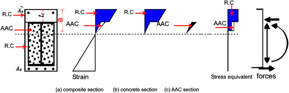
FIGURE 3. Theoretical stress–strain in the composite section when
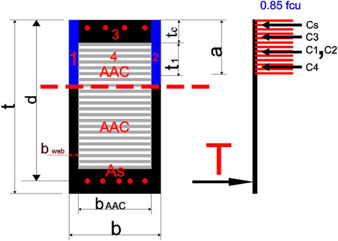
FIGURE 4. Internal forces on the composite section.
The computational analysis of flexure
The equilibrium of the forces should be applied to analyze each section. The internal forces in the section are the compression concrete force and compression steel force equal to the tension steel force in Eq. 4. Once the location of the neutral axis is determined and the internal forces are determined, the ultimate moment on the composite section (Mu) can be calculated by examining a moment when the point of application of the tension force occurs as follows:
Another part is when the depth of the compression zone (a) is bigger than the depth of the concrete above the autoclave aerated concrete (
when
The equilibrium of forces should be applied to analyze the section. The internal forces in the section are the compression concrete force, the compression AAC force, and the compression steel force that is equal to the tension steel force in Eq. 14. Once the location of the neutral axis is determined and the internal forces are determined by Eq. 14, the stress block distance a is calculated as the equilibrium of the forces by Eq. 15, and the ultimate moment on the composite section (Mu) can be calculated by considering the application point of the tension force by Eq. 17 as follows:
where
where (a) is the depth of the stress block, and (c) is the depth of the neutral axis at the maximum compression
Design of the shear in the composite section
Calculating the shear of the composite section was conducted in three parts as follows: the first part is the design of the shear of a solid beam. The ACI 318 requires that the allowable shear stress resisted by concrete only is given by Eq. 18, and the calculation of the shear stress carried by the steel stirrup is given in Eq. 19. Hence, the ultimate shear strength in Eq. 20 is as follows:
The second part determines the shear strength of the section with void chambers, as in Eq. 21.
The third part determines the shear stress of the autoclaved aerated concrete (AAC) section according to ACI 523.4R-09 ACI (2009) by Eq. 22 and the shear strength of the AAC section by Eq. 23.
Based on the three parts mentioned previously, the shear strength of the composite section is calculated using Eq. 24, as determined by the author, considering the ratio between the length of the concrete gaps between blocks AAC and the length of the blocks AAC at the longitudinal section.
where
Deflection of the composite section
The calculation of the deflection of the composite section is divided into two parts as follows: the first part calculates the equivalent modulus of elasticity of the composite section, and the second part calculates the effective moment of inertia of the composite section.
The first part: Computational calculation of the equivalent modulus of elasticity
It was determined that the strain of reinforced concrete equals the strain of autoclave aerated concrete at ACI 523.4R-09 [6]. Based on Hook’s law mentioned as follows, the equivalent modulus of elasticity of the composite section was computed using Eq. 31 and determined by the author.
where
The second part: Calculating the effective moment of inertia of the composite section
This model can also be used at the linear stage to evaluate the amount of composite behavior provided by the cross section, as shown in Figure 5. The stress distribution across the composite section can be used to assess the effective moment of inertia
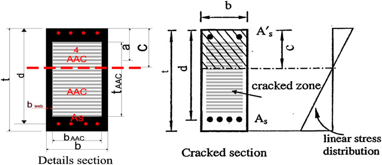
FIGURE 5. Cracking of the concrete section under applied loads.
According to ECP 2018, the cracking moment is determined using the following formula:
where y is the distance from the neutral axis to the extreme fiber regarding the tension for the uncracked section, fctr is the concrete tensile strength (N/mm2), and Ig is the gross moment of inertia omitting the influence of reinforcement (mm4) and (mm). The concrete tensile strength fctr in the ECP 2018 is provided by
where n is the modular ratio and is given by
Figure 5 (Naji et al., 2015) shows the cracking of the concrete section under applied loads.
Rustle
Validation of the proposed methods
Computational analysis of the composite sections explains the composite section of the beam and compares it with the finite element results conducted using ANSYS software. All beams had a rectangular cross section with a constant width and depth of 200 mm by 300 mm, respectively, with top and bottom longitudinal bars. The bottom bars were 20 mm, while the top bars were 6 mm, and the stirrup reinforcement was 6 mm and 10 mm. The bottom bars recorded a tensile yield strength of 560 Mpa. Top steel and stirrups recorded a tensile yield strength of 300 Mpa. The beam length was 3,000 mm with a 2,800 mm clear span, as shown in Figure 6. To consider the ability and capability of the concrete beam and infill beam modeling by applying the said techniques, an experimental test by Ade Sri Wahyuni [4] was modeled as the micro-sample. These authors have 12 models using AAC infill R.C., and the cross section of AAC blocks was 180 × 150 mm, the gap between the AAC blocks and the concrete was 43 mm, and the reinforcement stirrups were 6 mm and 10 mm, as shown in Table 1.
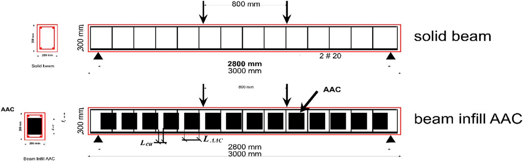
FIGURE 6. Details of the sections of beams.
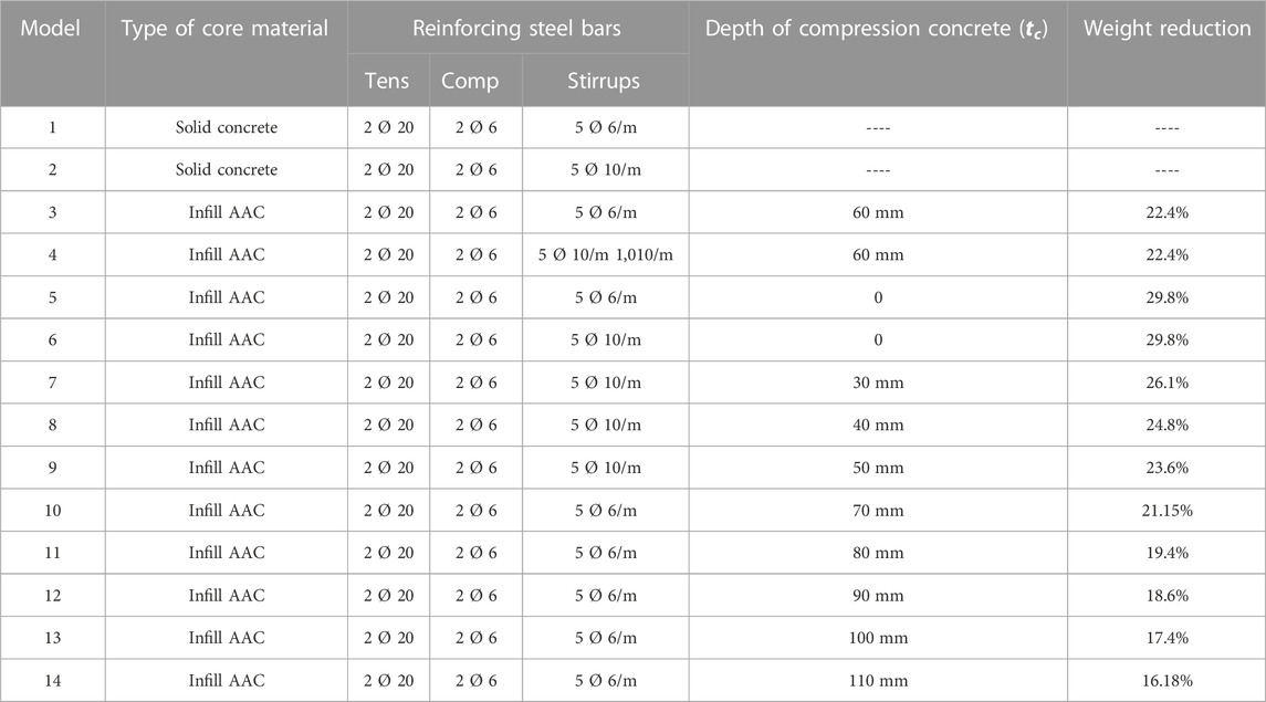
TABLE 1. Details of all the beams.
Schematic diagram of the study methodology
A scheme to explain the research methodology of the experimental, the finite elements, and the computational analysis and comparison between experimental, finite elements, and computational analysis as shown in Scheme 1.
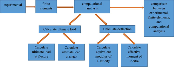
SCHEME 1. Schematic diagram of the study methodology.
Modeling the beams using ANSYS
The author used the ANSYS program to study the models. The ANSYS APDL program provides simulations of solid concrete elements with eight-node (solid65) at the command file at ANSYS APDL to connect ANSYS WORKBENCH as the solution, steel elements (180 link elements), and AAC solid elements with eight-node (solid65). The properties of the materials are shown in Table 2.
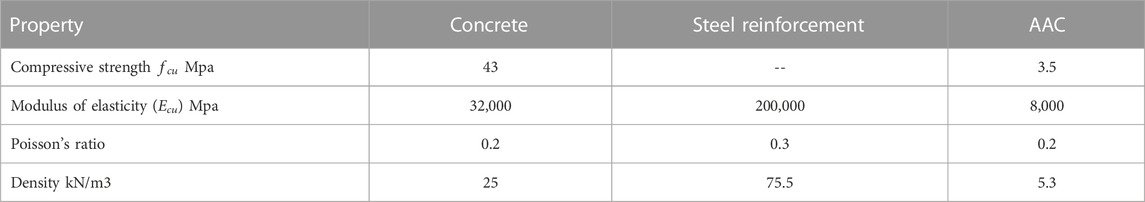
TABLE 2. Properties of the materials (Wahyuni, 2012).
The results of the ANSYS beams
Finite element analysis models were plotted to compare the failure load and deflection to the results, as shown in Figure 7.
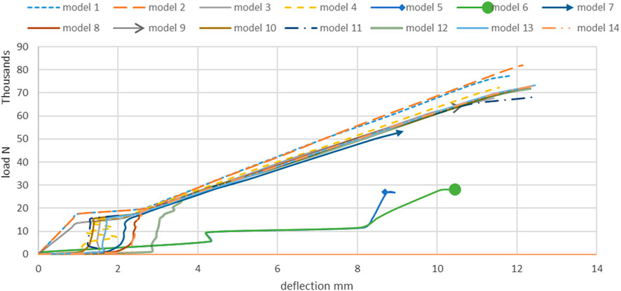
FIGURE 7. Load and deflection for the beam of the model by ANSYS.
ANSYS WORKBENCH graphical output
The output of the ANSYS analysis model is obtained, as shown in Figure 8.
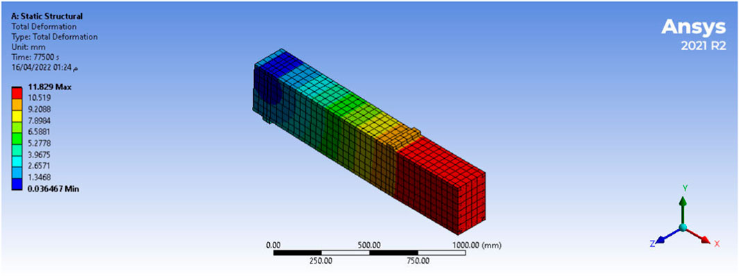
FIGURE 8. Model (Farid et al., 2017).
Results and discussion
The author determined the equations of the first crack, failure loads, flexure, and the dimensions of the compression zone from the first principles. The author also determined the equation of failed shear from the ECP 2018. Moreover, the comparison of the computational and finite element results is shown in Table 3. The table shows that the predicted results of the failure load were similar to the finite element for all models. The ratio of the computational calculation of failure loads shown by finite elements ranged from 0.89 to 1.1. The results show that the failure loads of the experimental and finite elements by ANSYS and computational calculation are slightly different from two other models (Farid et al., 2017, Al-Sherrawi, 2018). The experimental model (Farid et al., 2017) and the other model (Al-Sherrawi, 2018) failed at 78.9 kN and 78.6 kN, whereas the finite elements failed at 81.85 kN and 78 kN, and the computational calculation failed at 84 kN and 84 kN, respectively.
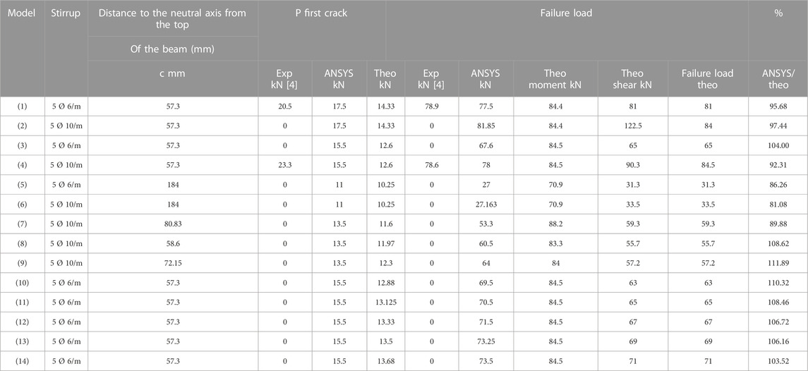
TABLE 3. Comparison between the experimental [4], finite elements, and computational analysis at the first crack and failure load.
The author concluded that the equation of the equivalent modulus of elasticity from Hooke’s law could be calculated. Moreover, the comparison of the computational and finite element results is shown in Table 4. The ratio of the computational calculation of the modulus of elasticity to the finite element ones ranged from 0.91 to 1.06.
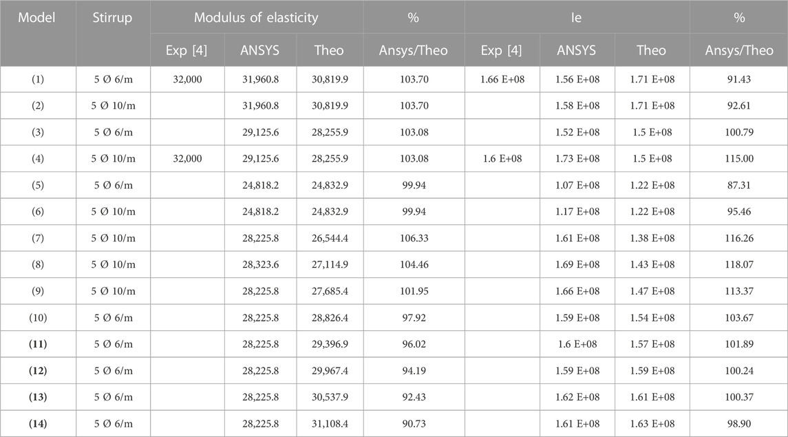
TABLE 4. Comparison results between the experimental, finite elements, and computational analysis at the modulus of elasticity and effective moment of inertia for all models.
An equation is presented for the effective moment of inertia and to calculate it in all sections. Moreover, a comparison of the computational and finite element results is shown in Table 4. The table demonstrates that the predicted outcomes of the effective moment of inertia are close to the finite element for all models. The ratio of the computational calculation of the effective moment of inertia to the finite element results ranged from 0.914 to 1.18.
The equation of the equivalent modulus of elasticity and the equation of effective moment of inertia were used to calculate the deflection of all models. Moreover, a comparison of the computational and finite element results is shown in Table 5. The ratio of the computational calculation deflection to the finite element results ranged from 0.87 to 1.15.
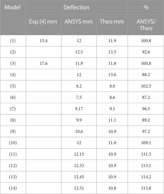
TABLE 5. Results for the comparison between experimental, finite elements, and computational analysis at the deflection of all of the different models.
Conclusion
In this study, an analysis of a composite section was proposed. Conceptual presumptions from the fundamental principles and Hook’s law serve as the foundation for the solution. The findings were compared with the finite element using ANSYS results and conducted using ANSYS software to verify the suggested analytical approach, and excellent agreements were found. The suggested and precise solution offers a better method for structural designers to determine flexure, shear, the equivalent elastic modulus, the effective moment of inertia, and deflection for the composite section. Additionally, the suggested analytical solution has the benefit of offering designers a better method for analyzing and designing a composite section without conducting a time-consuming 3D finite element analysis. The equation is based on the first principle to calculate failure loads, flexure, and the depth of the compression zone. The computational, experimental, and finite elements based on ANSYS results were compared. The failure loads of the experimental and finite elements by ANSYS and theoretical calculations were obtained from the solid beam model (Farid et al., 2017) and R.C. beam infill AAC model (Wahyuni, 2012). It was determined that the experimental model (Farid et al., 2017) and other model (Wahyuni, 2012) failed at 78.9 kN and 78.5 kN, whereas the finite elements failed at 77.5 kN and 78.5 kN; in contrast, the theoretical calculations failed at 81 kN and 84 kN.
⁃ The ratio of the theoretical calculation of the first cracking loads compared to the finite element results ranged from 0.89 to 1.1.
⁃ The author concluded that the equation of the equivalent modulus of elasticity from Hooke’s law was calculated. The ratio of the computational calculation of the modulus of elasticity to the finite element results ranged from 0.91 to 1.06.
⁃ The equation with the author’s effective moment of inertia was used to calculate all of the models’ respective effective moments of inertia. The ratio of the theoretical calculation of the effective moment of inertia to the finite element results ranged from 0.92 to 1.18.
⁃ The equation of equivalent modulus of elasticity and the equation of effective moment of inertia were used to calculate all models’ respective deflections. The ratio of the computational calculation deflection to the finite element results ranged from 0.87 to 1.15.
Recommendations for further research
⁃ A study should be conducted on the dimension between concrete and AAC blocks ratio in the LCSRC section.
⁃ A study should be conducted on the dimension between the
Data availability statement
The original contributions presented in the study are included in the article/supplementary material, and further inquiries can be directed to the corresponding author.
Author contributions
MO conducted the analysis of the composite section that was proposed. Conceptual presumptions from the fundamental principles and Hook’s law serve as the foundation for the solution. MA and HE-E used ANSYS software SA to study the portion of the study related to mathematics.
Conflict of interest
The authors declare that the research was conducted in the absence of any commercial or financial relationships that could be construed as a potential conflict of interest.
Publisher’s note
All claims expressed in this article are solely those of the authors and do not necessarily represent those of their affiliated organizations, or those of the publisher, the editors, and the reviewers. Any product that may be evaluated in this article, or claim that may be made by its manufacturer, is not guaranteed or endorsed by the publisher.
References
ACI (2009). Guide for design and construction with autoclaved aerated concrete panels (ACI 523.4r-09).
Al-Sherrawi, M. H. (2018). Khalid S. Mahmoud " shear and moment strength of a composite concrete beam. Int. Res. J. Adv. Eng. Sci. 3 (4), 128–132.
Benayoune, A., Abdul Samad, A. A., Trikha, D. N., and Abang Ali, A. A. (2008). S.H.M. Ellinna " Flexural behaviour of pre-cast concrete sandwich composite panel – experimental and theoretical investigations. Constr. Build. Mater. 22 (4), 580–592. doi:10.1016/j.conbuildmat.2006.11.023
EzzatFahmy, H., Shaheen, Y. B. I., Abdelnaby, A. M., and Abou Zeid, M. N. (2014). Applying the ferrocement concept in construction of concrete beams incorporating reinforced mortar permanent forms. Int. J. Concr. Struct. Mater. 8, 83–97. doi:10.1007/s40069-013-0062-z
Farid, A., Ahmed, A., Taleb, I., Nouran, H., and Saif, A-D. (2017), "Preparation of a new AAC-concrete sandwich block and its compressive behavior at quasi-static loading", Eng. Trans. Engng. Trans. 65, 371–389, .
Huang, W., Xiang, M., Bin, L., and Zeliang, L. (2019). "Experimental study on flexural behaviour of lightweight multi-ribbed composite slabs." hindawi advances in Civil engineering volume. Adv. Civ. Eng., 11. 1093074. doi:10.1155/2019/1093074
IbrahimHarba, S. I., and Mais, A. (2019). Numerical analysis of shear strength behavior of self-compact reinforced concrete two-way bubble deck slab with shear reinforcement. Mater. Sci. Eng. 518, 022050. doi:10.1088/1757-899x/518/2/022050
Naji, B., Elias, A., and Toubia, E. (2015). “Flexural analysis and composite behavior of precast concrete sandwich panel,” in Proceeding of the Concrete – Innovation and Design, fib Symposium, Copenhagen, May 18-20, 2015.
Rutvik, R. (2018). Flexural behavior and strength of doubly-reinforced concrete beams with hollow plastic spheres. Norfolk, Virginia: Degree of master of science (civil engineering) old dominion university.
Wahyuni, A. S. (2012). Structural characteristics of reinforced concrete beams and slabs with lightweight blocks infill. Bentley, Perth, Australia: Degree of Doctor of Philosophy of Curtin University.
Nomenclature
fctr concrete tensile strength
Ig gross moment of inertia
Keywords: AAC, composite section, ANSYS, equivalent modulus of elasticity, effective moment of inertia
Citation: Okasha MATA, Abdel Razek M, El-Esnawi H and Alkhatib S (2023) Analysis of lightweight composite sections with reinforced concrete infill with autoclaved aerated concrete (AAC). Front. Built Environ. 9:1149442. doi: 10.3389/fbuil.2023.1149442
Received: 21 January 2023; Accepted: 21 February 2023;
Published: 16 March 2023.
Edited by:
Mario Fagone, University of Florence, ItalyReviewed by:
Shaker Qaidi, University of Duhok, IraqRadosław Jasiński, Silesian University of Technology, Poland
Copyright © 2023 Okasha, Abdel Razek, El-Esnawi and Alkhatib. This is an open-access article distributed under the terms of the Creative Commons Attribution License (CC BY). The use, distribution or reproduction in other forums is permitted, provided the original author(s) and the copyright owner(s) are credited and that the original publication in this journal is cited, in accordance with accepted academic practice. No use, distribution or reproduction is permitted which does not comply with these terms.
*Correspondence: Mostafa Ali Taha Ali Okasha, bW9zdGFmYV9va2FzaGFAYXpoYXIuZWR1LmVn