 Maria Matheou
 Marios C. Phocas
 Eftychios G. Christoforou
 Andreas Müller
- 1Institute for Lightweight Structures and Conceptual Design (ILEK), University of Stuttgart, Stuttgart, Germany
- 2Department of Architecture, University of Cyprus, Nicosia, Cyprus
- 3Department of Mechanical and Manufacturing Engineering, University of Cyprus, Nicosia, Cyprus
- 4Institute of Robotics, Johannes Kepler University, Linz, Austria
Structures enabling transformability of buildings, components and materials at different levels gain significance in view of a sustainable built environment. Such structures are capable of obtaining different shapes in response to varying functional, environmental or loading conditions. Certain limitations of classic tensegrity and scissor-like structures, applied so far in an architectural and engineering context, are attributed to a limited number of possible configurations and a big number of actuators required. In this context, rigid-bar linkages offer a promising alternative with regard to constructability, modularity, transformability and control components integration. In achieving improved flexibility and controllability with a reduced number of actuation devices, a kinematics principle has been previously proposed by the authors that involves the reduction of the system to an externally controlled one degree-of-freedom mechanism in a multistep transformation process. The paper presents application of the kinematics principle in two classes of a transformable spatial rigid-bar linkage structure. Investigation of the system kinematics was conducted using parametric associative design. The kinematics principle is applied on a torus-shaped spatial structural system composed of planar interconnected linkages. Alternative motion sequences of multiple transformation steps by the planar linkages can be implemented for the stepwise adjustment of the joints to their desired values. The actuators employed are positioned at the ground supports and are detached from the main structural body. Thus, minimum structural self-weight, simplicity and reduced energy consumption become possible. The transformation approaches using parametric associative design are exemplified based on a selected motion sequence pattern. The case study demonstrates the high degree of control flexibility and transformability of the system.
1 Introduction
In recent years, technology has increasingly influenced architectural design and production, as well as the existing built environment, ranging from the material to the architectural and urban scale. Concurrently, technology has achieved a well-established understanding and shared appreciation within societies, architecture and engineering disciplines. Meanwhile, technology constitutes a key social and cultural component in the creation and maintenance of the built environment. In the past years, the construction materials and approaches applied led to a detrimental environmental impact, while an ongoing population growth takes place. Therefore, ecology and sustainability aspects of architecture are increasingly introduced in related discourses and cultural developments. Resources efficiency and performance, although primarily considered in an engineering and economic context, comprise integral interdisciplinary driving components in the actual physical production of architecture. Along these lines, flexibility, adaptivity and transformability in architecture become decisive in the creation of a sustainable built environment (Kronenburg, 2007; Christoforou et al., 2015). These terms imply that architectural production uses minimum natural resources and operates at maximum time-span with maximum efficiency and minimum technological disbursements. Thus, the design is oriented towards materials with advantageous mechanical properties, low self-weight, modularity, easy connectivity and expandability in construction, and technologies that enable adjustments and modifications with minimum means. In particular, building transformability needs to achieve maximum operational efficiency in timely changes of internal functional, external environmental and loading conditions, as well as in energy exploitation. Such attributes lead to improved users comfort, accommodation of changing needs, building aesthetics and operational costs, as well as safety. Flexibility forms a fundamental driving aspect in enabling such enhanced properties of the building structure and its communication logic with the living environment.
Flexibility in architecture has been associated in the 1960s with industrialization, mass production, prefabrication and modularity in providing repeatedly assembled, adjustable and mobile components (Phocas, 2017). Industrialization provided mass production, which signified the embodiment of a virtual system of modular coordination. The modular components would be interconnected and provide a high degree of refinement and precision, as well as integration of all the equipment necessary for ‘perfect environmental control’ (Wachsmann, 1989; Krausse and Lichtenstein, 2000; Hays and Miller, 2008). Industrialization further enabled flexibility in the building production, through transfer of the building and/or its components from the factory to the site and their assembly on-site through special joints that needed to be both functionally and cost efficient. This background was advocated for buildings that encompass features of assembly, disassembly and reassembly. Thus, the building structure was perceived as a by-product rather than an end-product, whereas the assembled space and volume would result from the material and the production process to determine form and function (Burkhardt and Hennicke, 1975).
Concurrently, in visionary architecture, there was a common perception that modular design could be used to constantly shape new environments with integrated technology (Newmann, 1961; Lin, 2010). In this framework, the term “megastructure” was introduced as an open structural concept into which prefabricated and modular capsule units could be plugged in or clipped on. These ideas embodied a rapid and flexible transformation of the structure (Banham, 1976; Lin, 2010). Thus, transformability derived from flexibility entailed in the functional disposition and operation of the building. The building form could evolve as the functional requirements changed and, at the same time, new technological and design developments could be employed (Domenig and Huth, 1967; Banham, 1976; Klotz, 1986; Wilhelm, 1996; Fiel, 2009). Designs featuring flexibility and transformability were interrelated by a number of mechanically, electrically and cybernetically controlled systems (Sadler, 2005). Visionary projects like the Plug-In City, 1964, shifted the attention from the megastructure to its kit-of-parts modular units. The latter enabled architecture to be perceived as a set of provisional relationships between components, rather than as fixed form, whereas temporality, distribution and mobilization of architecture described an important connection link in the achievement of maximum flexibility (Sadler, 2005). Architecture was promoted as a complex dispersed serviced situation, defined by the active involvement of the users, and characterized as indeterminate and situational.
In the engineering context, initially conceptualized and realized in actual scale, there were adaptive structures. Related advances, achieved in terms of adaptivity that preceded active transformability, were based on building mass reduction and high strength materials of relatively low elastic modulus. Representative examples comprise form-active systems of long-span lightweight tensile structures and elastic gridshells, in terms of their simulation and erection, as well as their load-deformation behavior (Engel, 1999; Lienhard and Knippers, 2013). Both, the erection process and the load-deformation behavior of the systems are of significance throughout the interactive design and analysis process, i.e., a sequence of equilibrium forms are developed, depending on the boundary conditions and the individual structural members stiffness. Thus, form, material and stress distribution for the systems are conditioned reciprocally (Otto, 1967; Finsterwalder, 2011).
An actual turn towards the vision for transformable structures was achieved through research and application of active structural control concepts in aerospace and mechanical engineering (Yao, 1972). ‘Kinetic Architecture’ postulated the necessity for an architecture that is not static; instead, it has the ability to adapt to time changes through systems with embedded actively controlled mechanisms (Zuk and Clark, 1970). Architectural form was envisioned to be free to adapt to changes affecting it. Thus, a range of forms, capable of meeting a range of input requirement changes during the life-span of the building, was a major design goal. The structural mechanism was envisioned to enable different geometrical configurations of the components through, among others, folding, sliding, expanding and transforming in size and shape. The control system would then direct the structure towards specified transformations, through mechanical, pneumatic, chemical, magnetic, or natural means.
Meanwhile, advances in computational platforms for simulation and numerical systems analysis, as well as in material design and motion systems, fertilized the development and realization of kinetic systems. These refer mainly to 1) deployability tasks, i.e., to unfold from a compact and retracted state to a predetermined, extended and fully deployed one, and 2) transformability tasks in interactive environments, mainly serving experimental, spatial cognition and environmental, energy related issues. In the first case, applications involve structural mobility, transportability and erectability at different sites and hostile environments with limited human access, i.e., temporary environments and aerospace (Pellegrino, 2001). In the second case, applications refer to different building elements, such as interior walls, floors, façade elements, sun-protection and renewable energy collection elements (Phocas et al., 2021). Main typologies comprise tensegrity, scissor-like and origami inspired systems (Pugh, 1976; Escrig, 1985; Chen et al., 2015; Li et al., 2019). The systems composition enables low self-weight, easy erection and extra flexibility with regard to the morphological outcome through employment of basic customized modules (Phocas et al., 2022).
Tensegrity structures comprise spatial self-stressed bar units of compression and tension members (Snelson, 1965; Pugh, 1976; Bel Hadj Ali et al., 2011). The compression members may be only indirectly, or directly interconnected, and stabilized through the tension members (Djouadi et al., 1998; Gantes, 2001). In the latter case, higher stiffness values of the system are achieved (Djouadi et al., 1998). Transformability in tensegrity structures is obtained through the replacement of structural joints or compression members with mechanical actuators, or the employment of tension members of variable-length and linear motion actuators (Hanaor, 1997; Tibert, 2002; Adam and Smith, 2008).
Scissor-like elements consist of pairs of bars interconnected with a rotational joint that enables the internal propagation of movement, from one component to another through integration of mechanical actuators (Escrig, 1985; You and Pellegrino, 1997; Maden et al., 2011). By allowing only one component to rotate, the kinematics principle reduces the actuation and control mechanism to a one degree-of-freedom (DOF) system. Various structural shapes can be obtained in the deployed state based on a respective differentiation of the joint location or bars length. In-between configurations, however, are only scaled versions of each other. Increased configurations variability is enabled through increase of the DOF of the mechanism, i.e., additional application of simple angulated elements (Hoberman, 1993; You and Pellegrino, 1997), scissor-hinge mechanisms (Akgün et al., 2010; Akgün et al., 2011), and universal scissor components (Alegria Mira et al., 2015). Likewise, the development of double scissor-pair transformable structures and hyperbolic paraboloids, based on 2-DOF mechanisms, aims at obtaining a variety of possible non-uniform shapes (Rosenberg and Thesis, 2009; Maden et al., 2015). Origami structures of rigid plates form a combination of corresponding linkages, since folding concentrates in the hinge-like creases that include the actuation mechanism (Chen et al., 2015).
The afore mentioned typologies have two main limitation aspects: On one hand, only individual target configurations are obtained through predefined motion trajectories of the system; on the other hand, the replacement of primary members with mechanical actuators leads to a substantial increase of the structural weight, complexity of the mechanism and energy amounts in the kinematics, negatively affecting the system’s performance (Phocas and Matheou, 2021). Introducing flexibility in kinematics implies that an increased number of target configurations may be obtained, as well as possible motion trajectories for each target configuration. Throughout the process of transformation, further in-between states of the system determine respective transformation states. Such flexibility means that the structure is capable of operating in an open-ended context of possibilities to accommodate different situations that may occur in time and the life-span of the building. In this sense, the structure is designed to further enable the choice of solutions out of a range of feasible alternatives, instead of unique and fixed solutions. Towards reducing the number of actuators needed for transformability, the structural members need to be bundled for actuation means, i.e., be connected with single actuation components, preferably detached from the main structure body.
Linkage-based systems, which comprise continuous series of one-dimensional, rigid bars interconnected by lower-order pairs, may constitute transformable structures with high flexibility and controllability (Thrall et al., 2012). A review on kinematic mechanisms, with reference to structural aspects of linkages, is included in (Mruthyunjaya, 2003). In achieving transformability, the systems still require a big number of actuators corresponding to their DOF. Instead, an appropriate control sequence of stepwise transformations may be applied in adjusting successively the system joints from the initial to the target values (Christoforou et al., 2015). The underlying kinematics principle involves the reduction of the system to an externally controlled 1-DOF mechanism in each transformation step. As part of these works two structural and transformation concepts were considered, namely the ‘effective crank–slider’ (ECS) and the ‘effective 4–bar’ (E4B). The kinematics of transformable rigid linkage structures, with either direct or cable-driven actuation, were investigated in simulations as well as experimentally (Phocas et al., 2015; 2019; Matheou et al., 2018; Christoforou et al., 2019; Phocas et al., 2020). A combined implementation of the two approaches proved to further enhance the system transformability and its controllability (Konatzii et al., 2021). Furthermore, a dual version of the effective crank–slider structural and control concept was investigated (Phocas et al., 2021). The basic structural mechanism comprises two crank–slider mechanisms sharing a common slider, which provides the kinematic coupling between the two parts. In all above cases, transformations may be implemented using alternative motion sequences and the most appropriate one may be selected upon considering different factors, including time-scale of transformations, functional, architectural criteria and objectives, and/or mechanical criteria, like, energy consumption, work done by the actuation system, brake torques, slider displacement, cable relative length variation etc. In addition, the basic approaches rely on a reduced number of actuators, detached from the main structure body, aiming to preserve minimum self-weight, structural simplicity, and reduced energy consumption during the transformation process.
The current paper applies the basic transformation approaches on a proposed torus-shaped spatial structure composed of rigid-bar linkages, and its transformability is investigated using a parametric associative design approach. The first contribution of the paper refers to the extension of the basic structural and transformability approaches of planar interconnected linkages, already demonstrated in previous studies, to the spatial circular section structures domain. These approaches provide a framework for spatial transformations without increasing the control complexity. In previous cases, the building envelope was produced through extrusion of a planar surface (defined by the basic planar linkage) in the longitudinal direction along a horizontal axis. In the present case, the building envelope is generated by revolving the planar surface about a vertical central axis. From an architectural point of view, the torus-like shape of the building provides certain benefits related to the spatial organization of uniform curved interior spaces with visual convergence towards the central atrium and circular external orientation and to the flexibility of the building configuration through possible divisions in multiple units. The circular perimeter of the building typology also has a lesser surface area, helping thermal conditions in cold climates. By extension, transformable torus-shaped buildings may provide improvements with regard to the functional disposition, natural lighting and ventilation of the spaces, energy efficiency, as well as aerodynamic shape under wind pressures. Last but not least, spatial transformations of the building produce impressive aesthetic effects. From a structural point of view, the torus-like shape of the structure enables in a practical way, transformations of the spatial system through control of only the active radial planar linkages. The length of the passive interconnecting members is adjusted accordingly. Both transformation approaches applied in the case study reconfirmed the advantages of the system for the proposed building typology, namely increased flexibility in its kinematics and reduced structural self-weight. The first mentioned advantage relates to an increased number of possible target configurations, transformation states and motion trajectories. The latter results from a reduced number of required actuators, which are also detached from the main structure body. The second contribution of the paper refers to the parametric associative design investigation of the transformability of the structure applied. The simulation studies in digital design are used to demonstrate the applicability of the approach in the spatial domain and exemplify the concepts. The case study demonstrates also that an investigation of the kinematics of the system at a preliminary design stage, may take place through digital parametric design tools, avoiding thus time-demanding numerical analysis processes. From a design methodology point-of-view, this may further enable increased integration and interdisciplinarity throughout a systematic design process in providing enhanced performance-based design outcomes.
2 Transformation approaches of the spatial structure
To provide a planned transformation and the required load-bearing behavior of the system at different operational states, such as intermediate states and target position, the basic transformation approaches are applied to planar linkage systems that are arranged and interconnected within the spatial structure. The actuated planar systems constitute active components of the structure, while the remaining members are passive links that adjust their length according to the active joints position. They also act as stabilizing components when locked at any operational state of the structure. The passive members are telescopic elements with a lock mechanism to transfer compression forces. Continuous cable diagonals are kept under tension to ensure the circumferential diaphragm of the structure. Transformations of the spatial system may involve coordinated, i.e., identical and synchronous, or non-coordinated motions of the individual active systems. Each joint of the active system is installed with a brake mechanism to provide locking and releasing in each transformation step based on a predetermined motion schedule. Furthermore, position sensors are installed on the joints serving as feedback information for the realization of the respective angle adjustments during transformations.
Transformability is provided in a rigid-bar linkage system with a pin and a sliding support, when a linear motion actuator is connected to the latter, Figure 1A. In that case, the ECS transformation method is followed. The sequence of individual internal joint releases and joint adjustment is determined in a preliminary motion schedule, while the joints at the supports remain unlocked throughout transformation, reducing the system to a 1-DOF mechanism. In the procedure followed, once a specific joint is adjusted through respective sliding of the system’s support by the actuator, it then remains locked until the target position is obtained. In any operational state of the system, both supports act as pin supports and all internal joints are locked. In a rigid-bar linkage system, with both supports pin connected to the ground, transformability is provided when a linear or rotational motion actuator is connected to one of the supports, Figure 1B. In that case, the E4B transformation method is followed. Two individual internal joints are unlocked in each transformation step, provided that the ground supports remain throughout transformation unlocked, and one joint is adjusted to the desired value. Again, from that point on, each adjusted joint in a step remains locked until the target position is obtained. A limitation of the motion trajectory of the system during transformation involves its passing through singular configurations or their vicinity (Norton, 2008). At a singularity the actuator may become unable to move further the system, which may follow different paths when slightly disturbed (Park and Kim, 1999).
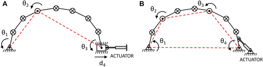
FIGURE 1. Approaches for stepwise transformations of a planar system with multiple serially connected rigid links (⊗: locked joint, ʘ: unlocked joint, △: pivoted–to–the-ground joint, □: slider joint, —: physical link,—–: effective link): (Α) ECS transformation approach; (Β) E4B transformation approach.
In the ECS case, the linear actuator controls the position of the slider and in the E4B case, it adjusts the position of the associated joint angle. The operation of the motion actuators as well as the activation of the joint brakes, are managed by the central control system, using sensory feedback information. Different types of linear actuators can be used including hydraulic systems. Double-acting hydraulic cylinders use pressurized hydraulic fluid to provide accurate bidirectional motion. In general, hydraulic systems move slowly but they are capable of generating large forces. An alternative type of linear actuator would be the spindle drive. In that case an electric motor is used to rotate a threaded shaft while its nut moves back-and-forth along its length. In the E4B concept, the actuated joint may be alternatively installed with a rotational, high-torque (geared) motor.
The building envelope should be of low self-weight, high elasticity and strength in obtaining only elastic deformations during transformation, without stress interactions with the primary structure. In addition, the envelope structure is required to be flexible in order to accommodate cases of dissimilar configurations assumed by any adjacent actuated bar linkages. Principally, a dedicated secondary structure is used to support the membrane envelope and compensate possible relative deformations of the primary structure during transformation.
3 The torus-shaped spatial structure
The torus-like building shape is a representative shape of spatial circular-section buildings enabling specific architectural features, including uniform, curved interior spaces, an atrium and the potential of dividing the structure into multiple building units (Steadman, 2015). Real-world applications of the specific typology are classified according to the building scale. At small building scale, applications are associated with exhibition and pavilion usages, e.g., ICD/ITKE research pavilion, 2010, with a torus shape, and Faraday pavilion, 2012, with a half torus shape (Knippers, 2011; Tornabell et al., 2014), as well as temporary habitats (Kolarevic, 2003). At large building scale, applications refer to museums, e.g., American air museum in Duxford, 1997, with a torus segment shape (Schittich and Geisel, 1998), research premises, e.g., the Institute of Legal Medicine in Madrid, 2006, with a torus shape (Zaera-Polo, 2009), as well as airport terminal envelope structures, e.g., the Jewel Changi airport terminal in Singapore, 2019, with a spindle torus shape (Tahmasebinia et al., 2021).
The case example in the present study refers to a torus-shaped spatial structure of hollow circular section that consists of sixteen 8-bar linkages, radially arranged on the circumference. The primary linkages of 1.75 m long individual bars are joined consecutively and interconnected through peripheral links of variable length; the structural members consist of round hollow aluminum profiles of 168.3/6.3 and 101.6/4 mm, respectively. Continuous diagonal cables of 20 mm diameter and variable length provide the structural diaphragm.
In order to achieve transformability of the system, the primary linkages arranged in the radial direction are activated, whereas the peripheral connecting links act as passive elements. In the case example, only coordinated transformations have been performed on each individual actuated planar linkage. Accordingly, the required number of joint brakes are released in each transformation step for the reduction of the system to a 1-DOF mechanism, based on a motion schedule, selected according to specific kinematics and static response criteria among different feasible ones. The completion of the transformation steps allows the system to obtain the target position. Furthermore, any intermediate transformation state of the system, may also provide a further structural form of specific operational time for the building. Thus, the transformation approach allows the form to continually evolve. When the target position or a provisional transformation state of the system has been obtained, all joints are then locked by applying the brakes.
The building structure is symmetrically transformed from an initial to a target shape of equal span to demonstrate the proposed transformations following both considered approaches, Figure 2. In its initial configuration of a double quasi-paraboloid elevation shape, the structure has a span of 4.90 m on each side and a corresponding maximum height of 4.96 m; in its target configuration of a double quasi-ellipsoid elevation shape with equal span on each side, the structure obtains a maximum height of 3.60 m. The inner circular open area has a diameter of 6.0 m. While the selected initial and target configurations are only indicative ones for the transformability of the structure, other shapes can be selected according to respective criteria and objectives. In the present case, the initial configuration of the building may serve for example, functional purposes for increased roof height, improved natural light distribution within the interior spaces, appropriately oriented photovoltaic panels integrated to the building envelope, and inclined roof surfaces to prevent deposit of snow. The target configuration may serve for example, improved utilization of the interior area, acoustics and natural ventilation of the interior spaces, heating and cooling performance of the building, as well as an aerodynamic building shape. The initial and target configurations are defined by the following vectors, which include the internal joint angles:
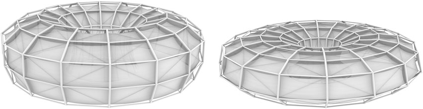
FIGURE 2. Transformable building in initial and target position.
A motion sequence of the system has been selected for each of the transformation approaches, Figure 3. The sequence order follows an anticlockwise joints adjustment starting from the second internal joint of the system next to the outwards support, J7, Figure 3. In the last transformation step of the ECS, the last joint of the outwards ground support connected to the slider is adjusted together with the joints, J1, J8, J9. The last transformation step of the E4B involves the adjustment of both joints next to the supports, J1, J9, and the joints, J2, J8.
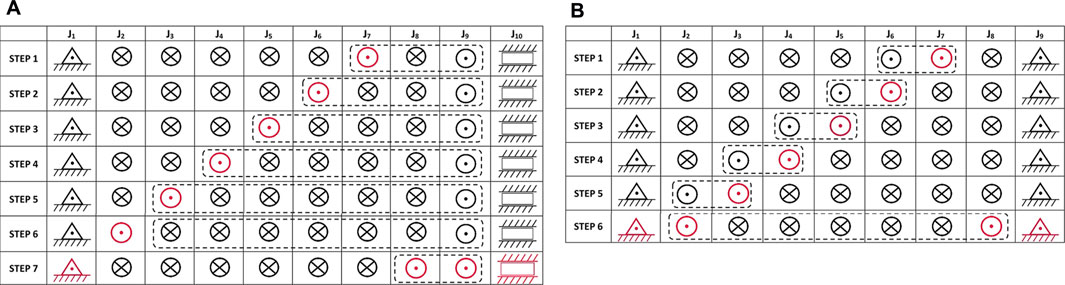
FIGURE 3. Scheduling tables for the ECS and E4B control sequences realizing the required shape adjustment on the linkage with eight serially connected members (⊗: locked joint, ⊙: unlocked joint, △: pivoted–to–the-ground joint, : slider joint). Dashed-line encirclements denote the effective coupler links. The red colored symbols represent the currently adjusted joints: (A) Sequence based on the ECS approach; (B) Sequence based on the E4B approach.
3.1 Parametric associative design
The parametric associative design methodology applied in this study aims at simulating the transformation process of the spatial structure from the initial to the target position based on the considered transformation approaches. The use of computational tools can be extremely beneficial in the study of kinetic form (Terzidis, 2003). 3D dynamic computational methods attribute a paradigm shift in visualizing the suitable configurations with predefined geometric properties and constraints during the decision-making process (Kilian, 2006). The authors have previously explored transformable structural systems through the prism of mechanical systems using different methods and tools (2D Working Model, SolidWorks, Matlab/Simulink). In this study, the mechanical components of the proposed transformable structure have been translated into constraints, variables, and dependencies to facilitate the ability to integrate engineering knowledge into the early-stage of the architectural design. This workflow has been implemented in Rhino/Grasshopper using Pufferfish and Karamba3D plugins as standard components, Figure 4. Specifically, the design exploration aims to provide different dimensions of the ECS and E4B mechanisms in architecture, a better understanding of the interplay between static components and flexible joints that may be controlled, and ultimately, the kinetic form and behavior of a spatial structural system.
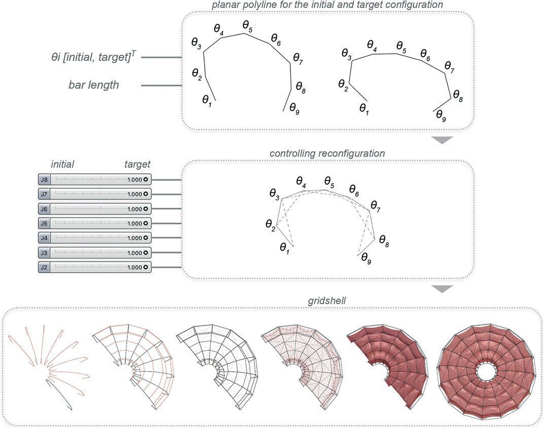
FIGURE 4. Building sections and isometric views of the transformation steps based on the E4B approach.
To form the torus-shaped spatial structure, three steps were taken: a planar polyline with flexible joints was generated, the transformation steps were controlled by having initial and target positions, and the spatial structure including the tensile building envelope was generated. The process enables design flexibility and creativity while using topological, functional and geometric constraints as design drivers (Kilian, 2006). Although the constraints are included in the parametric model, it also allows for the investigation of various angles for the initial and target positions retaining the dynamic relationships between the components that form the spatial structure.
In the first step, a planar polyline with eight segments was generated by defining the angles for the initial and target position of the structure in a ‘construct domain’ component, such as: θ2 = [158, 115]Τ; θ3 = [130, 125]Τ; θ4 = [157, 165]Τ; θ5 = [148, 168]Τ; θ6 = [157, 165]Τ; θ7 = [130, 125]Τ; θ8 = [158, 115]Τ degrees. Moreover, the bars length has been defined at 1.75 m. In this parametric model, the geometric constraints technically referred to a predefinition of the angles, number of the bars, and length of the bars. Different shapes can be generated by changing the aforementioned parameters. In our study, an initial position of a quasi-paraboloid elevation shape with a maximum height of 4.96 m and a target position of a double quasi-ellipsoid elevation shape with a maximum height of 3.60 m were both generated.
Based on the generated polyline, a ‘slide within domain’ component (Pufferfish) was used to slide between the initial and target position. This implies that the selection of the ECS and E4B sequence order can be explored in various possible scenarios while representing the geometric design of the transformable torus-shaped structure. Likewise, the unlocked and locked joints can be controlled by sliding to “0” or “1” respectively as explained in section 3. To ensure that two bars of the linkage readjust their angles in the right direction by means of inwards rotation, an ‘anchor’ component in Kangaroo was used. In fact, the additional lines shown in Figure 4, connect the joints θ1-θ3, θ2-θ4, θ3-θ5, θ4-θ6, θ5-θ7, θ6-θ8, and θ7-θ9. The joint J1 has been defined as fixed joint and the joint J9, as linear sliding joint in the xy-axis for the ECS, while both joints J1 and J9 have been set as fixed joints for the E4B. Given the way the kinetic mechanisms functions, these constraints have been incorporated into the parametric model.
In order to create the 3D shape of the structure, planes were radially positioned in 16 divisions. Subsequently, the primary polylines in each plane were connected through secondary horizontal lines and the diagonal members were added as well. Finally, Karamba3D components were used to build the tensile envelope.
3.2 Kinematics simulation
The corresponding transformation steps of the building structure for each transformation approach are presented in Figure 5 and Figure 6 in the form of vertical sections and isometric views of the building. In the simulations based on the ECS, only the last, outwards joint, J9, in each planar system is assumed to be the actuated one connected to the sliding block. In the simulations based on the E4B, only the first, inwards joint, J1, is assumed to be actuated through a rotational actuator. In each transformation step, one joint angle of each planar system is adjusted to its target value, while all rigid bars are only allowed to move above the horizontal ground level. The transformation of the building structure, following the ECS, presents a rotation in direction opposite to the sliding supports in the first two steps, in the same direction, in the subsequent two steps and again, in opposite direction, in the last two steps before achieving the target position. Following the E4B, the building structure rotates outwards in the first two steps, and inwards in the remaining three steps preceding the target position.
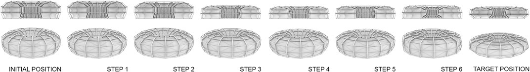
FIGURE 5. Parametric associative design of the transformable building based on the ECS and E4B approach.
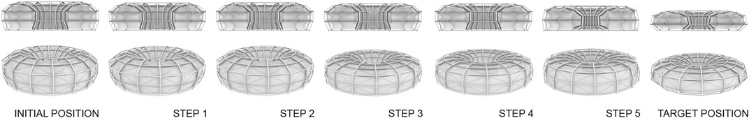
FIGURE 6. Building sections and isometric views of the transformation steps based on the ECS approach.
For the transformation of the building between an initial and a target position there exist a plethora of different sequences, which can be implemented. The number of alternative options with reference to the transformation process and obtained intermediate transformation states may be limited by architectural and engineering requirements and objectives. In all cases, any transformation involves slow motions of the structure, so that inertia effects of the system are insignificant. Nevertheless, the trajectory followed during transformation is significant in terms of related criteria, such as architectural ones (e.g., allowable changes in building dimensions in open landscape, or in dense urban context), functional ones (e.g., required height of the building according to its usage, furniture and devices), aesthetics, as well as structural ones (e.g., allowable eccentricities that result to corresponding brake torques and/or peak response values in successive transformation steps, and consequently required actuation energy). Furthermore, the time-scale of a transformation is directly related to the external changing conditions. While architectural and functional related objectives, such as changes of internal usages, require less frequent transformations, bioclimatic and energy related ones, such as sun-protection, natural lighting, ventilation, lighting of interior space and photovoltaics implementation, require transformations in continuous mode, on daily and seasonal basis. External loading conditions, as for example snow fall and wind pressures on site, involve irregular, temporary configurations of the building to be obtained. Examples of related architectural and engineering criteria and objectives are presented in Kolaveric and Parlac (2015). The intermediate transformation states of the building directly relate to the process itself, as a result of the motion schedule applied in the kinematics of the system. Favorable building configurations obtained may also refer to the aforementioned architectural, functional, energy-related and engineering criteria and objectives. For the selection and implementation of the most favorable motion sequences of the building structure, automated optimization-driven approaches may be applied to satisfy certain criteria and objectives, instead of a traditional selection procedure (Kallioras et al., 2016). An automated optimization-driven selection of a motion sequence of a 9-bar linkage based on the E4B approach according to structural criteria set is presented in Matheou et al. (2020).
3.3 Structural modularity
The modular assembly of the structure favors flexibility at different levels. At the building level, different autonomous building units may be realized, when one or more planar linkages are disconnected through removal of the secondary system between them. The corresponding envelope is rearranged to provide continuity of the façade planes. At the structure level, the number and length of the links determine the boundaries of the inner space, as well as the span of the structure, also providing expandability in radial direction. In terms of the system composition, it applies that a large number of links will allow for more smooth contours of the inner spaces, but also for more complex shapes to be realized and more versatility to serve the actual purpose of transformation. However, structural and motion planning complexity increase, as well as the number of sensors and brakes to be installed on the structure.
The repeated use of modular linkages allows for a standardized construction procedure and application of future assembly through construction robotics (Bock, 2015; Gharbia et al., 2020). Corresponding robotic technology aspects for building on-site construction include automated robotic assembly (Nam et al., 2007; Lee et al., 2008) and autonomous robotic assembly (Chu et al., 2009; Chu et al., 2013). In either case, employment of robotic systems leads to a decrease of the construction time and cost, enhancement of the workers safety and consistent quality.
4 Conclusion
Transformability in architecture was initially pursued through increase of flexibility in the construction and structural disposition of buildings. This was made possible through industrialization and mass production of modular components. In the engineering context, transformability in terms of adaptivity was first employed in numerical simulations and the actual erection of special innovative structures, of long-span lightweight tensile structures and elastic gridshells. Following this development, active structural control was proposed for achieving adaptive systems in architecture. Meanwhile well-known solutions of deployable structures, based on tensegrity, scissor-like and origami inspired typologies, allow for transformability with limited number of shapes, often at a cost of considerable self-weight increase due to the direct implementation of actuation components on the structure body. In achieving increased flexibility in transformability with minimum actuation means, rigid-bar linkage structures constitute a promising solution. The kinematics are based on the reduction of the system to an externally controlled 1-DOF mechanism in each successive step of a transformation sequence. The kinematics concept involves two basic approaches, namely the ECS and the E4B approach. Both approaches have been used to transform a torus-shaped spatial structure from an initial to a target position, following a specific motion sequence. For the kinematics investigation, parametric associative design was used. The case study demonstrates: 1) the applicability of the transformation approaches to spatial circular section structures, and 2) the investigation of the kinematics of the building through parametric associative design. Congruently to previous numerical studies conducted of planar interconnected linkages it was reconfirmed through the digital design approach applied: 1) the high degree of flexibility and potential of the system enabled through the transformation approaches to provide a further number of possible building shapes according to temporary transformation states or target positions of the system, 2) the reduced structural self-weight preserved during transformations due to reduced number of used actuators, detached from the main structure body. Furthermore, the present study demonstrates the possibility to consider the kinematics of the system at a preliminary design stage in providing essential information on transformations and compatibilities of the system with regard to spatial limitations and objectives governing the design. Future work includes the development of a framework of automated motion planning and optimization procedures for the generation of optimal motion trajectories and sequences in providing respective building shapes based on specific criteria and objectives.
Data availability statement
The original contributions presented in the study are included in the article/Supplementary Material, further inquiries can be directed to the corresponding author.
Author contributions
MM, MP, EC, and AM drafted the manuscript. All authors revised and edited the manuscript.
Funding
This work was partly funded by the Deutsche Forschungsgemeinschaft (DFG, German Research Foundation)—Project-ID 279064222—SFB 1244.
Acknowledgments
The content of this manuscript was presented in part at the second International Conference on Architecture, Technology and Innovation 2021, Phocas and Matheou (2021). The authors would like to thank Matthias Kip for his involvement in the parametric model.
Conflict of interest
The authors declare that the research was conducted in the absence of any commercial or financial relationships that could be construed as a potential conflict of interest.
Publisher’s note
All claims expressed in this article are solely those of the authors and do not necessarily represent those of their affiliated organizations, or those of the publisher, the editors and the reviewers. Any product that may be evaluated in this article, or claim that may be made by its manufacturer, is not guaranteed or endorsed by the publisher.
References
Adam, B., and Smith, I. F. C. (2008). Active tensegrity: A control framework for an adaptive civil-engineering structure. Comput. Struct. 86, 232215–242223. doi:10.1016/j.compstruc.2008.05.006
Akgün, Y., Gantes, C. J., Kalochairetis, K., and Kiper, G. (2010). A novel concept of convertible roofs with high transformability consisting of planar scissor-hinge structures. Eng. Struct. 32, 2873–2883. doi:10.1016/j.engstruct.2010.05.006
Akgün, Y., Gantes, C. J., Sobek, W., Korkmaz, K., and Kalochairetis, K. (2011). A novel adaptive spatial scissor-hinge structural mechanism for convertible roofs. Eng. Struct. 33 (4), 1365–1376. doi:10.1016/j.engstruct.2011.01.014
Alegria Mira, L., Filomeno Coelho, R., Thrall, A. P., and De Temmerman, N. (2015). Parametric evaluation of deployable scissor arches. Eng. Struct. 99, 479–491. doi:10.1016/j.engstruct.2015.05.013
Bel Hadj Ali, N., Rhode-Barbarigos, L., and Smith, I. F. C. (2011). Analysis of clustered tensegrity structures using a modified dynamic relaxation algorithm. Int. J. Solids Struct. 48 (5), 637–647. doi:10.1016/j.ijsolstr.2010.10.029
Bock, T. (2015). The future of construction automation: Technological disruption and the upcoming ubiquity of robotics. Autom. Constr. 59, 113–121. doi:10.1016/j.autcon.2015.07.022
B. Burkhardt, and J. Hennicke (Editors) (1975). “IL14 adaptable architecture,” Mitteilungen des Instituts für leichte Flächentragwerke (Stuttgart, Germany: University of Stuttgart).
Chen, Y., Peng, R., and You, Z. (2015). Origami of thick panels. Sci 349, 6246396–6246400. doi:10.1126/science.aab2870
Christoforou, E. G., Müller, A., Phocas, M. C., Matheou, M., and Arnos, S. (2015). Design and control concept for reconfigurable architecture. Mech. Des. 137, 042302. doi:10.1115/1.4029617
Christoforou, E. G., Phocas, M. C., Matheou, M., and Müller, A. (2019). Experimental implementation of the ‘effective 4-bar method’ on a reconfigurable articulated structure. Struct 20, 157–165. doi:10.1016/j.istruc.2019.03.009
Chu, B., Jung, K., Chu, Y., Hong, D., Lim, M.-T., Park, S., et al. (2009). “Robotic automation system for steel beam assembly in building construction,” in Proceedings of the 4th International Conference on Autonomous Robots and Agents, Wellington, New Zealand, 10-12 Feb. 2009, 38–43. doi:10.1109/ICARA.2000.4803937
Chu, B., Jung, K., Lim, M.-T., and Hong, D. (2013). Robot-based construction automation: An application to steel beam assembly (Part I). Autom. Constr. 32, 46–61. doi:10.1016/j.autcon.2012.12.016
Djouadi, A., Motro, R., Pons, J. C., and Crosnier, B. (1998). Active control of tensegrity systems. J. Aero Eng. 11, 37–44. doi:10.1061/(asce)0893-1321(1998)11:2(37)
Domenig, G., and Huth, E. (1967). Propositionen = propositions = propositions. Bau. + Wohnen = Construction + habitation = Building + home 21, 184–186.
Escrig, F. (1985). Expandable space structures. Int J Space Struct 2 (1), 79–91. doi:10.1177/026635118500100203
Gharbia, M., Chang-Richards, A., Lu, Y., Zhong, R. Y., and Li, H. (2020). Robotic technologies for on-site building construction: A systematic review. J Build Eng 32, 101584. doi:10.1016/j.jobe.2020.101584
Hanaor, A. (1997). “Tensegrity: Theory and application,” in Beyond the cube. Editor J. F. Gabriel (New York: John Wiley & Sons), 385–408.
Hays, K. M., and Miller, D. (2008). Buckminster fuller – starting with the universe. New York: Whitney Museum of American Art and Yale University Press.
Hoberman, C. (1993). Unfolding architecture: An object that is identically a structure and a mechanism. Arch Des 63, 53–59.
Kallioras, N. A., Lagaros, N. D., and Avtzis, D. (2016). “A new metaheuristic inspired by bark beetles for solving engineering problems,” in Proceedings of the 11th HSTAM International Congress on Mechanics, Athens, Greece, 27–30 May, 2016, 27–30.
Killian, A. (2006). Design innovation through constraint modeling. Int J Archit Comput. 4 (1), 87–105. doi:10.1260/147807706777008993
Knippers, J. (2011). “Digital technologies for evolutionary construction,” in Computational design modeling. Proceedings of the design modeling symposium. Editors C. Gengnagel, A. Kilian, N. Palz, and F. Scheuer (Berlin: Springer), 47–54.
Kolarevic, B. (2003). Architecture in the digital age. Design and manufacturing. Abingdon: Taylor & Francis.
Kolarevic, B., and Parlac, V. (2015). Building dynamics: Exploring architecture of change. New York: Routledge.
Konatzii, P., Matheou, M., Christoforou, E. G., and Phocas, M. C. (2021). Versatile reconfiguration approach applied to articulated linkage structures. J Arch Eng 27 (4), 04021039. doi:10.1061/(ASCE)AE.1943-5568.0000517
Krausse, J., and Lichtenstein, C. (2000). Your Private Sky. R. Buckminster Fuller Design als Kunst einer Wissenschaft. Zurich: Lars Mueller.
Lee, S., Nam, H., Lee, Y., and Park, J. (2008). “A new type of bolting robot for steel-frame structure constructions,” in Proceedings of the international conference on control, automation and systems (Seoul, Korea: COEX), 2256–2260. doi:10.1109/ICCAS.2008.4694183
Li, S., Fang, H., Sadeghi, S., Bhovad, P., and Wang, K. W. (2019). Architected origami materials: How folding creates sophisticated mechanical properties. Adv Mater 315, 1805282. doi:10.1002/adma.201805282
Lienhard, J., and Knippers, J. (2013). Considerations on the scaling of bending-active structures. Int J Space Struct 28, 137–148. doi:10.1260/0266-3511.28.3-4.137
Lin, Z. (2010). Kenzo tange and the metabolist movement urban utopias of modern Japan. Abingdon, Oxon: Routledge.
Maden, F., Aktas, E., and Korkmaz, K. (2015). A novel transformable structural mechanism for doubly ruled hypar surfaces. J Mech Des 137, 031404–031414. doi:10.1115/1.4029231
Maden, F., Korkmaz, K., and Akgün, Y. (2011). A review of planar scissor structural mechanisms: Geometric principles and design methods. Architect Sci Rev 54, 246–257. doi:10.1080/00038628.2011.590054
Matheou, M., Kallioras, N. A., Lagaros, N. D., and Phocas, M. C. (2020). Automated optimal motion sequence of a 9-bar linkage. Front. Built Environ. 6, 1321–1410. doi:10.3389/fbuil.2020.00132
Matheou, M., Phocas, M. C., Christoforou, E. G., and Müller, A. (2018). On the kinetics of reconfigurable hybrid structures. J Build Eng 17, 32–42. doi:10.1016/j.jobe.2018.01.013
Mruthyunjaya, T. S. (2003). Kinematic structure of mechanisms revisited. Mech Mach Theory 38, 279–320. doi:10.1016/S0094-114X(02)00120-9
Nam, H., Choi, W., Ryu, D., Lee, Y., Lee, S.-h., and Ryu, B. (2007). “Design of a building robot for constructing steel structure,” in Proceedings of the international conference on control, automation and systems (Seoul, Korea: COEX), 1946–1949. doi:10.1109/ICCAS.2007.4406667
Otto, F. (1967). Tensile structures: Design, structure and calculation of buildings of cables, nets and membranes. Cambridge: MIT Press.
Park, F. C., and Kim, J. W. (1999). Singularity analysis of closed kinematic chains. J Mech Des 121 (1), 32–38. doi:10.1115/1.2829426
Pellegrino S. (Editor) (2001). Deployable structures (Vienna: International Center for Mechanical Sciences, CISM courses and lectures), 412.
Phocas, M. C., Christoforou, E. G., and Dimitriou, P. (2020). Kinematics and control approach for deployable and reconfigurable rigid bar linkage structures. Eng Struct 208, 110310. doi:10.1016/j.engstruct.2020.110310
Phocas, M. C., Christoforou, E. G., and Matheou, M. (2015). Design, motion planning and control of a reconfigurable hybrid structure. Eng Struct 101 (10), 376–385. doi:10.1016/j.engstruct.2015.07.036
Phocas, M. C., Christoforou, E. G., Theokli, C., and Petrou, K. (2021). Reconfigurable linkage structures and photovoltaics integration. J Build Eng 43, 103201103201–103210320112. doi:10.1016/j.jobe.2021.103201
Phocas, M. C., Matheou, M., and Haase, W. (2022). Transformable building structures in architectural engineering education. Archit Struct Constr 2, 183–198. doi:10.1007/s44150-022-00022-3
Phocas, M. C., Matheou, M., Müller, A., and Christoforou, E. G. (2019). Reconfigurable modular bar structure. J Int Assoc Shell Spat Struct 60 (1), 78–89. doi:10.20898/j.iass.2019.199.028
Phocas, M. C., and Matheou, M. (2021). “Revisiting transformable structures in architecture,” in Proceedings of the 2nd International Conference on Architecture, Technology and Innovation 2021, Izmir, Turkey, 24.09-25.09.21. Designing for Uncharted Territories. 4–15.
Phocas, M. C. (2017). Technology-driven design approaches to utopia. Stuttgart: Edition Axel Menges.
Rosenberg, D. (2009). Designing for uncertainty. Novel shapes and behaviors using scissor-pair transformable structures. Boston: MIT. M.Sc. Thesis.
Schittich C., and Geisel I. (Editors) (1998). “Flugzeugmuseum in Duxford, england”, Det, 38, 988–992.
Snelson, K. (1965). Continuous tension, discontinuous compression structures. U.S. Pat. 3 (169), 611.
Steadman, P. (2015). Architectural doughnuts: Circular-plan buildings, with and without courtyards. Nexus Netw J 17 (3), 759–783. doi:10.1007/s00004-015-0270-8
Tahmasebinia, F., Wang, Y., Wu, S., Ho, J., Shen, W., Ma, H., et al. (2021). Advanced structural analysis of innovative steel–glass structures with respect to the architectural design. Bldg 11, 208. doi:10.3390/buildings11050208
Terzidis, K. (2003). “Expressive form,” in A conceptual approach to computational design (New York: Spon Press).
Thrall, A. P., Adriaenssens, S., Paya-Zaforteza, I., and Zoli, T. P. (2012). Linkage-based movable bridges: Design methodology and three novel forms. Eng Struct 37, 214–223. doi:10.1016/j.engstruct.2011.12.031
Tibert, G. (2002). Deployable tensegrity structures for space applications. Ph.D. Thesis. Stockholm: Royal Institute of Technology.
Tornabell, P., Soriano, E., and Sastre, R. (2014). “Pliable structures with rigid couplings for parallel leaf-springs: A pliable torus pavilion,” in Mobile and rapidly assembled structures IV: Proceedings of the 4th MARAS Conference. Editors C. Brebbia, and N. De Temmerman (Ostend, BelgiumSussex: Wit Press), 11117–13127. doi:10.2495/MAR140011
Wilhelm, K. (1996). Auf der Suche nach der verlorenen Unsterblichkeit: Technische Utopien in der Architektur des 20. Jahrhunderts. Graz: Akademische Druck- u. Verlagsanstalt.
Yao, J. T. P. (1972). Concept of structural control. J Struct Div 98 (ST7), 1567–1574. doi:10.1061/jsdeag.0003280
You, Z., and Pellegrino, S. (1997). Foldable bar structures. Int J Solids Struct 15 (34), 1825–1847. doi:10.1016/S0020-7683(96)00125-4
Zaera-Polo, A. (2009). Patterns, fabrics, prototypes, tessellations. Archit Des 79 (6), 18–27. doi:10.1002/ad.975
Keywords: transformable structures, flexibility, linkage structures, kinematics, motion schedule, parametric associative design
Citation: Matheou M, Phocas MC, Christoforou EG and Müller A (2023) New perspectives in architecture through transformable structures: A simulation study. Front. Built Environ. 9:1051337. doi: 10.3389/fbuil.2023.1051337
Received: 22 September 2022; Accepted: 16 January 2023;
Published: 27 January 2023.
Edited by:
Shijia Pan, University of California, Merced, United StatesReviewed by:
Yuqing Gao, University of California, Berkeley, United StatesAni Luo, Harbin Engineering University, China
Copyright © 2023 Matheou, Phocas, Christoforou and Müller. This is an open-access article distributed under the terms of the Creative Commons Attribution License (CC BY). The use, distribution or reproduction in other forums is permitted, provided the original author(s) and the copyright owner(s) are credited and that the original publication in this journal is cited, in accordance with accepted academic practice. No use, distribution or reproduction is permitted which does not comply with these terms.
*Correspondence: Maria Matheou, bWFyaWEubWF0aGVvdUBpbGVrLnVuaS1zdHV0dGdhcnQuZGU=