 Paul Marker*
 Achim Bleicher
- Chair of Hybrid Structures-Structural Concrete, Brandenburg University of Technology Cottbus-Senftenberg, Cottbus, Germany
In structural engineering, active structures that combine the principles of lightweight construction with bending elastic component behavior are increasingly being investigated. For the realization of a prototype of an active hybrid roof structure at the laboratory of Hybrid Structures at BTU Cottbus-Senftenberg, preliminary investigations on a case study are conducted in the framework of this publication in order to improve the design process of these types of structures. These active hybrids require a higher design effort than classical structures from the field of structural engineering due to a larger number of relevant objectives. Consequently, this study devotes special attention to these essential target criteria and their mathematical formulation. Furthermore, in order to improve the efficiency of this design process, a hierarchical method is derived that is subdivided into two successive partial procedures, which contain specific heuristics that are developed. In this method, after structural optimization, an optimal actuator placement is performed. The subject of a design process involving optimal actuator placement is relatively unexplored for active structures in which components are subjected to large elastic bending deformations and is therefore the focus of this study. In order to verify the functionality of the method and the plausibility of the results of the derived partial methods, a validation of the methodology is performed. Therefore, results of analyses of an active truss structure are compared with those of an active hybrid structure, both derived using the presented method. In addition to validating results, the study intends to investigate whether the performance of an active hybrid structure generated by the proposed method is sufficiently competitive compared to a state-of-the-art active truss structure derived by the same procedure.
1 Introduction
Active structures are used in different fields of application. In our built environment, they are still relatively rare. In general, the design of these type of structure on a larger scale should mainly be based on the principles of lightweight construction. Resource efficiency in the sense of material efficiency can be achieved by applying these principles. This, in turn, can contribute to more energy-efficient actuation (Wang and Senatore, 2020) as lighter structures typically require less energy for transformation than structures that exhibit a higher mass. According to the requirements of a lightweight design, the load transfer in structures should primarily be achieved by normal forces. Therefore, kinetic truss structures with jointed connections are often realized to meet this demand. In this way, bending stresses in the supporting structures can be avoided during transformation. Another relatively new approach is represented by kinetic bending active structures, where bending is part of the concept; consequently, significant bending stresses are involved in the load transfer. Using this structural concept, bending elastic component behavior can reduce the number of required actuators while offering high adaptability and elegant transformations (Schleicher, 2015; Lienhard and Gengnagel, 2018). The conscious utilization of the bending elastic behavior can also already be discovered in other fields of application, for example, in small, everyday applications, often made of polymers and known as compliant mechanisms (Howell et al., 2013). If a design should be intended to follow the principles of lightweight construction and still benefit from the advantages of bending elastic component behavior, it is necessary to make a compromise. As a result, new promising transformable structural solutions can be generated, which are referred to as active hybrid structures in the framework of this publication. Consequently, it might be beneficial to develop a design process for this new kind of structure.
For the derivation of the previously mentioned design process, it is advisable to consider the state of the art of active structures because this type of structure, equipped with active components such as actuators and sensors, is already being studied for a considerable time. Therefore, several approaches for optimal design realizations in different fields of application can be found. For instance, well-known investigations regarding convertible roof structures have been performed by Otto and Burkhardt (1972). Membrane structures are often used in these studies, which is certainly advantageous in terms of lightweight construction. Sobek (2016) also aimed to design active structures as light as possible. In these studies, ultra-lightweight structures that can adapt to different loading conditions are realized by applying the concept of load path management. Ultra-lightweight structures are more prone to vibration due to their low mass. In order to overcome such problems, another approach from the field of active structures can be applied. Through active vibration control, vibrations can be significantly reduced by an appropriate actuation concept. For example, in Bleicher et al. (2011), an active vibration control of a stress ribbon footbridge was investigated. Considering these aforementioned existing approaches for the design of active structures and their different aims, it appears necessary to derive suitable target criteria for creating an effective design process for active hybrid structures. By using appropriate objectives, it is also possible to provide a more accurate comparison with conventional active truss structures in order to prove the competitiveness of the novel structures.
During the design process of active hybrid structures, several of these objectives have to be aimed at. A structural geometry has to be determined, which allows an ideal transfer of the external loads. After that, a suitable set of actuators has to be determined. In addition, an active bending transformation has to be realized. Consequently, the degree of complexity associated with the formulation of meaningful objectives and the definition of suitable design variables can become relatively high when searching for optimal active hybrid structures (Marker et al., 2019). This is due to the amount of target criteria to be considered for such structures and the complexity of their structural geometries. These can be defined by parametric models and have to be analyzed by means of nonlinear calculations. A simplification of the resulting overall problem can be achieved by a hierarchical subdivision of the whole problem into subsequent procedures like the ones conducted in Sobieszczanski-Sobieski et al. (1987); Engels et al. (2004); Loos et al. (2018). Such a division in independent substeps of highly complex optimization problems is often used to increase the efficiency of optimization algorithms regarding the computational effort. This kind of approach can be found in various fields of application. For example, in Zeng et al. (2020), such an optimization is performed for a variable-stiffness laminated plate using an adaptive hierarchical approach with truncated hierarchical B-splines. Moreover, large optimization problems arise in energy supply systems, for instance, under uncertain energy demand. A design method using hierarchical mixed-integer linear programming (MILP) is used in Yokoyama et al. (2021) to maximize the robustness of these systems. Furthermore, a new hierarchical optimization approach for a kinematic machine with five degrees of freedom is presented in Zhao et al. (2021). This methodology can simplify the difficult analysis of a highly nonlinear and strongly coupled system. In Rodrigues et al. (2002), a hierarchical computational procedure for optimizing material distribution as well as the local material properties of mechanical elements is described. Each of these problems from the fields mentioned previously is intentionally not solved as one optimization problem, where all parameters are optimized simultaneously. Hence, for the challenging task of designing active hybrid structures, a hierarchical division of the overall problem into sub-problems also seems to be reasonable. Regarding the derivation of active hybrid structures, this aspect can lead to the idea of a successive execution of structural optimization and a subsequent optimal actuator placement.
It is also possible to benefit from the advantages of hierarchical partitioning within structural optimization. When comparing common procedures of that type, such as topology optimization, BESO optimization, or shape optimization, it appears that the method of shape optimization especially offers potential for a hierarchical approach. Its complexity can be further simplified by reducing the number of design variables and their definition ranges or by introducing relationships between them. For shape optimization of trusses, this can be achieved, for example, by imposing symmetry conditions helpful basics regarding this type of optimization can be found, for instance, in Tejani et al. (2018). The topic of optimal actuator placement for active structures is currently intensively investigated by Heidingsfeld et al. (2017); Wagner et al. (2018); Senatore et al. (2019); Geiger et al. (2020); Steffen et al. (2020). In this context, Wagner et al. (2020) examined the arrangement of actuators with respect to a serial or parallel configuration. Another recent study addresses optimal motion planning (Sachse and Bischoff, 2021). In this investigation, an identification of an optimal deformation path between an initially undeformed geometry and a prescribed deformed configuration is performed. In addition, an approach for the placement of actuators is derived in Sachse et al. (2021). However, the research field of actuator placement for kinetic bending active structures is still relatively unexplored. Hence, the development of a methodical and effective design procedure that unifies these aspects into a beneficial approach for the design of active hybrid structures seems to be promising. Thus, for an effective determination of an appropriate actuator set, an algorithm is required, which allows an efficient calculation of large solution spaces. Therefore, a greedy-heuristic, which is also known from the field of artificial intelligence, can be employed. This type of algorithm can be especially useful when dealing with large data sets in order to achieve a reduction of the computational effort (Russell and Norvig, 2016). However, the result of such a procedure may not necessarily be the global optimum due to assumptions in intermediate steps (Jungnickel, 1999). This circumstance is often accepted for the sake of enormous savings regarding computational costs. In Manohar et al. (2020), a greedy algorithm is used for actuator and sensor placement. Within these investigations, a combined maximization of observability and controllability for linear time-invariant systems is targeted. Two greedy algorithms are employed in Guo et al. (2020). This approach allows an actuator placement that minimizes the average energy consumption for transformation while satisfying a structural controllability requirement.
Based on all these considerations, in this publication, we present a hierarchical method for the design of active hybrid structures. This work extends our previous research, where we have already obtained encouraging results by deriving an active hybrid structure based on topology optimization (Marker et al., 2019).
The present publication is structured as follows: Useful target criteria from the mentioned fields are derived and explained in Section 2. In particular, new objectives are presented for the evaluation of the bending elastic component behavior as they are significant for the design of active hybrid structures. In Section 3, the whole method for the derivation of such structures is presented. The complexity of the posed overall design problem is relatively high. This resulted in a large number of potential structural variants, each leading to an enormous number of possible actuator sets to be analyzed. Hence, a hierarchical procedure is proposed in order to reduce this complexity. Thus, structural optimization is performed in the first process step and an optimal actuator placement in the following step. Initially, the method is described in general in subsection 3.1, followed by a mathematical description in subsection 3.2. In Section 4, applications and validations of the proposed method are conducted. The basic information about the software environment and state-of-the-art optimization algorithms, which are used for validation purposes, are described in subsection 4.1. In subsection 4.2, the proposed method is validated using the benchmark examples of two active truss structures. First, a well-known structure from the field of structural optimization is used for the validation of the presented sub-method of actuator placement. Another example of an active truss structure, described by a parametric model, serves as reference for a later direct comparison. Moreover, the sub-method of structural optimization is validated using the mentioned optimization algorithms. Subsequently, in Section 4.3, the proposed method is used to derive an optimized active hybrid structure, which is described by a parametric model with similar boundary conditions like in the previous example and corresponds to a well-known bionic principle. Furthermore, the presented novel target criteria are observed within the framework of this example. Moreover, the performance of the introduced structural optimization procedure is compared to that of state-of-the-art optimization algorithms for this example as well. In addition, full enumerations are examined for the respective partial problems in order to illustrate the performance of the derived method. Finally, to elaborate potentials associated with the design of active hybrid structures, in Section 4.4, the performance of results from subsections 4.2 and 4.3 is compared and discussed. Concluding, Section 5 summarizes the investigations and gives an outlook on further studies.
2 Formulation of Target Criteria
In the following, some suggestions for possible target criteria are presented, which may be helpful for the design of active hybrid structures. These different objectives of the posed multi-criteria optimization problem can be arranged in the vector of target criteria:
wherein
and
The suggested single target criteria f1 to f8 are explained in Eqs. (5) to (18). Due to the desired large deformations, calculations are conducted according to the third-order theory, in which the rotations of the system are also taken into account. In this calculation method, after each iteration step, the stiffness matrix of the deformed system is formed again and the calculation is continued until equilibrium is reached.
The target criterion f1 represents the stiffness at an arbitrary predefined node of the structure in a selectable preset direction:
in which F is the applied force, and d the resulting deformation, both in the specified direction at this node.The criterion f2 is the mass of the structure:
The target f3 is the eigenfrequency of the structure
which can be calculated using the circular eigenfrequency ω determined solving the general eigenvalue problem:
wherein K is the nonlinear stiffness matrix
and M is the mass matrix of the system. As indicated in Eq. 9, the nonlinear stiffness matrix K can be subdivided into its elastic part KE, the element stiffness matrix of large displacements KU (also called initial displacement or slope matrix), and the geometric stiffness matrix KG. Within the context of the investigations presented in this study, these matrices are internally calculated by Karamba3D. The employed element formulations are based on those by Tenek and Argyris (1998). The calculation of the geometrical stiffness matrix is conducted using the formulas of Rubin and Schneider (2002). The large displacement stiffness matrix is calculated according to Crisfield (1997), (2003).
One of the target criteria contained in
This objective represents a useful measure for the kind of load transfer occurring in the structure; hence, it enables a classification between lightweight construction and active bending. A further target criterion for the evaluation of active bending, denoted by f5, is the curvature κ, which is a decisive objective for the shape of elegant transformations:
Therefore, the curvature is evaluated at b points per rod and summed up. In this formula, the deflection of the system at the examined point k is represented by w (xk).
The main objective concerning the actuator placement is denoted by f6:
where the transformation u evaluates the displacement of a certain predefined node in a specific desired direction. The target criterion f7 represents the amount of energy Π which is needed for the actuation:
In these investigations, in addition to the strain energy resulting from normal forces ΠN (Eq. 14) and the strain energy resulting from bending moments ΠM (Eq. 15), the potential energy Πpot (Eq. 16) and the kinetic energy Πkin (Eq. 17) are considered:
As indicated in Eqs. (16) and (17), for the determination of the potential and the kinetic energy for each of the r members of the structure, one half of the mass mj of the jth rod is placed at its two endpoints. In Eq. 16, Δhj,1 and Δhj,2 denote the absolute values of the corresponding amount of transformation in self-weight direction at the respective nodes. The velocities of the two endpoints of the respective member j are denoted by v1,j and v2,j in Eq. 17. For their calculation, a virtual time, in which the transformation occurs in a steady motion, is assumed for the examples examined in Section 4. To determine the relation between the necessary energy Π and the gained transformation u, the target criteria f6 and f7 can be combined to the objective f8 that represents the efficiency of the actuation:
For each of the proposed target criteria, a corresponding weighting factor is introduced. These can be arranged in the vector of weightings:
which is subdivided analogously to the vector of target criteria in Eqs. (2) to (4):
All of the initially formulated target criteria f1 to f8 can contribute to the evaluation of the performance of an active hybrid structure concerning the three mentioned fields and to find a suitable design. Due to the fact that not all of them are always equally important for the desired optimization and obviously are partially related to each other, the corresponding weighting factors are also meant to enable the selection of a subset of the proposed target criteria that are relevant for the specific purpose of the respective optimization by setting their weightings to zero. Nevertheless, during the design process, it can be meaningful to observe these values despite not selecting them as target criteria explicitly. Of course, the deduction of further target criteria f9 to fz is possible, whereas it is recommended to reduce the amount of chosen target criteria to a necessary minimum. Furthermore, the weightings of the considered target criteria need to be chosen in a way that the resulting values of the single target criteria are scaled to an equal magnitude in order to achieve reasonable results if the target criteria are combined into a single objective (Eq. 25). This also holds regarding the desired minimization and maximization of the respective target criteria.
Finally, the design of an active hybrid structure can be conducted by a multi-criteria optimization using the vector of weighted target criteria (specified within the scope of this publication for the sake of completeness and for information purposes only):
or alternatively by formulating a single-criterion optimization problem using the combined objective (in the present study employed for structural optimization and subsequent actuator placement (Section 4.2; Section 4.3)).
In this context, retracing all target criteria to the same unit, such as energy, may be useful, as shown by Wang and Senatore (2020) or Senatore and Reksowardojo (2020). Thus, an overall energy balance could be determined and optimized in order to achieve more energy-efficient structures.
The optimization problems investigated in the framework of Section 4.2 and Section 4.3 are unconstrained but could easily be extended to constrained optimization problems. Hence, some of the proposed objectives f1 to fz can be involved as constraints instead. Since the solution space of the posed optimization problem is very large, a hierarchical method is derived. In Section 3, a mathematical description of this method is presented.
3 Hierarchical Method for the Design of Active Hybrid Structures
3.1 General Description of the Method
Hierarchical optimization involves the decomposition of the problem into several levels of sub-problems. These sub-problems are of lower complexity compared to the overall optimization problem; hence, a solution can be found more efficiently (Loos et al., 2018). Due to this simplification, the solution does not necessarily correspond to the global optimum. Because of the high complexity of the problem and the many parameters involved in the framework of these investigations, this simplification is intentionally made in order to improve the efficiency of the proposed method. This methodology is subdivided into two successive partial procedures containing specific heuristic approaches. It provides an efficient search for the best solutions of active hybrid structures based on a parametric model. Structural optimization is performed before an optimal actuator placement. It is prioritized in this investigation due to the importance of the static load transfer of the resulting structure. Furthermore, the structural geometry is essential as a basis for the actuator placement. It should be mentioned that performing structural optimization first increases its impact on the overall result. Initially, the first partial method, that is denoted as the operator Γ, first sorts the design parameters βi (Eq. 30) of the given parametric model according to their determined influence on the objective fw,I. Subsequently, a hierarchical optimization, which is depicted in Figure 1A, is employed. Starting with the first parameter, in each step e, every parameter βi,e,d, d = 1,…, p is varied successively whereas the parameters βi,e,1 to βi,e,d−1 are set to their optima
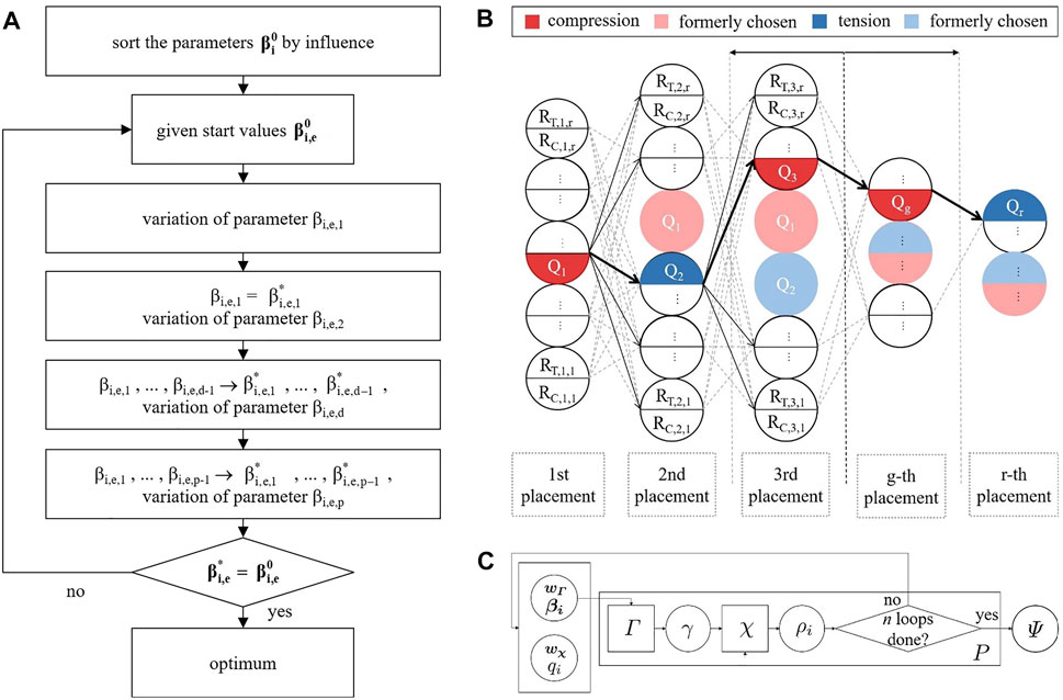
FIGURE 1. Flowcharts of (A) operator Γ—structural optimization, (B) operator χ—choice of actuators, and (C) entire hierarchical method—successive execution of operator χ after operator Γ.
After this process step, the first run of the entire method is completed. In further loops, additional neighboring solutions on the Pareto front can be determined iteratively by applying the operators Γ and χ in further loops. The flowchart of the complete derived method is depicted in Figure 1C. A more detailed mathematical description of the developed method can be found in Section 3.2. The presented method is then performed on application examples in Section 4.
3.2 Mathematical Description of the Method
In this section, the mathematical description of the developed procedure is pointed out:
The aim is an effective derivation of an appropriate design for an active hybrid structure Ψ, which depends on the vector of weighting of the target criteria w, the vector of parameters β defining the parametric model of the structure, and the number of actuators q that shall be selected during the procedure of the actuator placement. This result Ψ is defined as the optimum of the results of all n conducted single executions of the derived method:
Of course, the better the total optimum is approximated, the more the amount of runs n of the method aims toward infinity. The optimum ρi of the ith single execution of the method can be determined by the aid of the introduced composite function P (wi, βi, qi):
This composition P (wi, βi, qi) is defined as the successive execution of a hierarchical structural optimization procedure Γ and a subsequent actuator placement, performed by a greedy algorithm, denoted by the operator χ:
In this equation, χ is the execution of an actuator placement with qi actuators, according to Figure 1B, and Γ is a hierarchical structural optimization of a predefined parametric model that is defined by the vector of parameters βi, as described by the flowchart in Figure 1A, whereby
must hold as the result of the structural optimization γ has to be included in the initial domain Ω defined by the initially set up parametric model. The vector βi can contain different kinds of parameters describing the calculation model like geometrical variables of the parametric structure, support conditions, loading, material and cross section parameters.
The weighting of the target criteria w is assigned as indicated in Eqs. (19) to (23).
The actuation is modeled by strain load cases which lead to a prescribed (constant) stroke for all chosen actuators to ensure comparability between the different actuator positions, whereby exactly g actuators are selected in the gth step of the heuristic that are composed of compression and tension actuators. The fact that actuators should generally not be subjected to bending is neglected in the scope of these investigations as, in our preliminary work (Marker et al., 2019), we are able to demonstrate that appropriate alternative solutions can be found by means of sophisticated structural design, for example, by adjusting the static system through additional sliding details. Furthermore, bendable actuators are already a topic of research (Ballas, 2007; Ham et al., 2009; Prabhu et al., 2020), although in the large scale required for structural engineering, this has not yet been achieved.
The following equation describes the strain load cases
Tg,h represents the set of tension actuators that are examined during the hth iteration in the gth step of the heuristic. The next equation describes the strain load cases for all rods in QC, which represent compression actuators in the hth iteration of the gth step of operator χ:
Here, Cg,h represents the set of compression actuators that are examined during the hth iteration in the gth step of the heuristic, whereby 1 ≤ g ≤ q ≤ r, with r being the number of rods of the structure and q the amount of actuators to be chosen, has to hold.
Each examined set of actuators in the hth iteration of the gth step of the heuristic can then be denoted by the following equation:
The chosen set of actuators in the gth step of the heuristic can then be described as follows:
where H is the number of possible combinations that have to be examined during the gth step. Compared to the amount of combinations that would result from a complete search, an enormous benefit in computation time could be reached. This becomes obvious, comparing the necessary evaluations according to Figure 1B to the resulting amount of combinations for a complete search that can be determined using Eqs (35) or (36) if the kinds of actuators to be chosen vary within one set, and is depicted in Figure 2.
The chosen actuator sets of a certain substep are always subsets of the solution of a later step of χ:
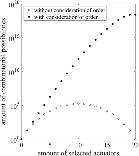
FIGURE 2. Number of combinatorial possibilities for the selection of an amount of actuators for r = 20 rods with and without consideration of the order.
4 Application and Validation of the Presented Method
4.1 Software Environment and Aspects of Validation
A significant part of the research conducted in this study is realized using the parametric modeling software Grasshopper (Rutten, 2014). It is embedded in the CAD software Rhinoceros 3D (McNeel, 2018). The necessary implementations of the developed procedures are carried out using Visual Studio (Microsoft, 2019) and the programming language C#. The performed FEM-calculations within the method are executed using the software Karamba3D (Preisinger, 2018). It offers the capability to analyze parametric models within very short computation times. Moreover, its kernel provides a good basis for the development of new methods with own implementations. A validation of the FEM analyses is conducted with the FEM software Sofistik (SOFiSTiK AG, 2018). Comparative structural optimizations are performed using the software GOAT (Rechenraum GmbH, 2021) (Table 1 and Table 2). GOAT provides an interface to NLopt (nonlinear-optimization package). This free library includes some gradient-based and direct search algorithms. For example, DIRECT, the linear trust region method COYBLA (Powell, 1994), the cubic trust region method BOBYQA (Powell, 2009), CRS2 (Kaelo and Ali, 2006), a stochastic direct search method, and a Nelder–Mead variant of the SUBPLEX algorithm (Rowan, 1990) are included in this library. A schematic representation of the software environment used in the framework of these studies is depicted in Figure 3.
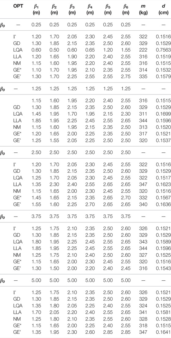
TABLE 1. Results of parameters β1,…, β6 for different initial β0 (Figure 6), mass m (Eq. 6), and deformation d (Eq. 5) of optimization algorithms OPT with maximum run-time of that needed by the Γ operator (Figure 1A) as early stop criterion; GOAT-algorithms (Figure 3): GD = global deterministic (DIRECT), LQA = local quadratic approximation (BOBYQA), LLA = local linear approximation (COBYLA), NM = Nelder–Mead (SUBPLEX), GE* and GE’ = global evolutionary (CRS2) best* and worst’ result of 5 runs; visualization of the result of the Γ-operator for β0 = (2.5 2.5 2.5 2.5 2.5 2.5)T (Figure 6E).
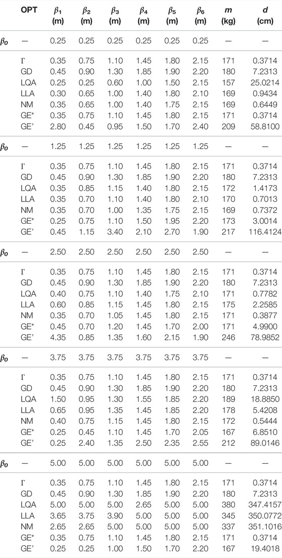
TABLE 2. Results of parameters β1,…, β6 for different initial β0 (Figure 8), mass m (Eq. 6), and deformation d (Eq. 5) of optimization algorithms OPT with maximum run-time of that needed by the Γ operator (Figure 1A) as early stop criterion for each β0; GOAT algorithms (Figure 3): GD = global deterministic (DIRECT), LQA = local quadratic approximation (BOBYQA), LLA = local linear approximation (COBYLA), NM = Nelder–Mead (SUBPLEX), GE* and GE’ = global evolutionary best* and worst’ result of 5 runs; visualization of results for β0 = (2.5 2.5 2.5 2.5 2.5 2.5)T (Figures 8E, 9A,C).
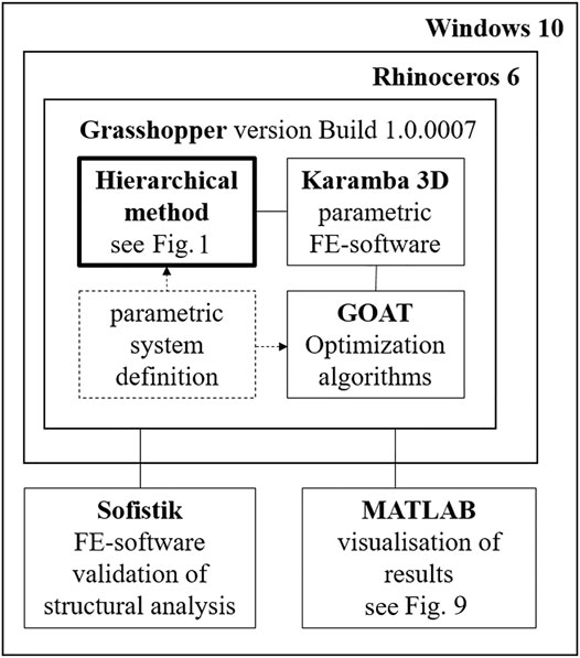
FIGURE 3. Software environment in the framework of the study.
4.2 Benchmark Active Truss Structures
The investigations within this section include some validations with state-of-the-art active structures. In this context, statically determined truss structures are examined. This type of structure is often the subject of investigations concerning the optimization of active structures, for instance, in Senatore et al. (2018) or Reksowardojo et al. (2019). These structures, consisting of jointed truss members, are especially effective if light structures or structures with low energy consumption have to be designed. For such active trusses, no bending stresses are introduced into the structural members during actuation. In addition to representing a benchmark study and improving the reproducibility of results, these investigations also indicate differences in results compared to those of an active hybrid structure (Section 4.3), derived using the same method (Figure 1C).
Michell structures (Michell, 1904) are well known in structural engineering and have already been approximated as a truss by Wiedemann (1996). Hence, an approximation of the Michell structure will be used in the following investigations in order to validate the plausibility of the actuator placement conducted by the operator χ (Figure 1B). For this purpose, a steel truss is approximated for a quadratic design space of 10 m by 10 m (Figure 4B). It has 18 truss members with a circular cross section with a diameter of 10 cm. The targeted transformation direction u (Figure 4C) is horizontal and intended to have the exact opposite direction compared to the shape determining single load (Figure 4B). Therefore, due to the force flow-oriented geometry of the truss, a plausible actuator positioning is expected to correspond to the sign of the normal forces of the structure resulting from the shape determining load case. Hence, for members with a compressive force as a result of the single load, the placement of a compression actuator is expected. Vice versa, the placement of tension actuators is expected for members under tension. For the corresponding analysis (Figures 5A–C), an actuator stroke of 10 cm is applied for each actuator. In Figure 5C, red rods indicate the placement of compression actuators, and blue members have been chosen to be tension actuators. The remaining (gray) parts of the structure do not contain any actuators.
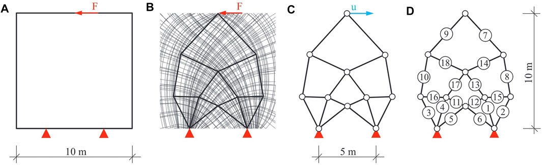
FIGURE 4. Michell truss approximation according to Wiedemann (1996) as basis structure for validation of operator χ, (A) design space and loading, (B) approximation of trajectory lines and shape determining single load, (C) Michell truss and transformation direction u, and (D) corresponding numbers of individual actuator analysis (Figure 5A).
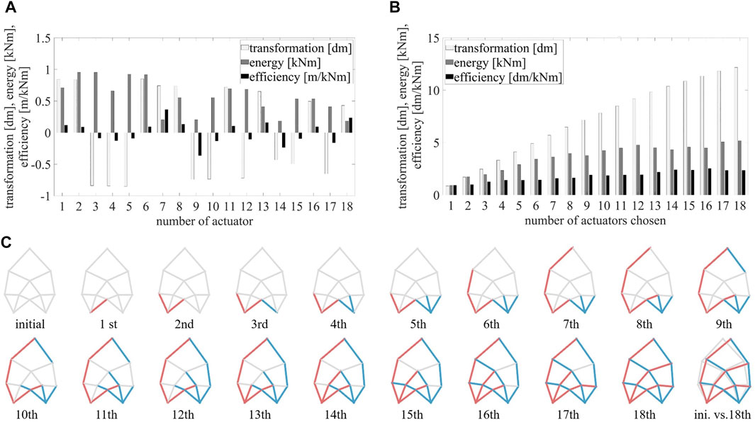
FIGURE 5. Bar charts of (A) individual actuator placement (corresponding numbers of actuators (Figure 4D) and (B) heuristic actuator placement corresponding to (C) stepwise process of choice for the placement of 18 actuators (red: compression, blue: tension actuators) by operator χ.
Observing the results of the individual actuator placement analysis (Figure 5A), it is noticeable that the positions 1, 2, and 6, that are located at the right support achieve the best transformation (Eq. 12) for the placement of a compression actuator. In contrast, position 7, located at the top, attains a particularly high efficiency (Eq. 18). Considering the results of the axis-symmetric partners of the actuators, it can be seen that they have the same magnitude but with a negative sign. Thus, a corresponding analysis for tension actuators shows that these positions are particularly well suited for the placement of tension actuators.
Furthermore, a heuristic actuator placement is performed for the structure (Figure 4C) using the χ operator (Figure 1B) targeting a maximal transformation of the tip point in u-direction. Observing the results of the stepwise actuator placement (Figure 5C), it is particularly noticeable that the actuators are placed preferably at the supports. This seems plausible considering the results of the individual actuator placement (Figure 5A) and the fact that the largest lever arm to the tip point is located at the supports. Furthermore, it can be observed that for a complete placement of 18 actuators, as expected, the kind of actuator placed corresponds to the sign of the normal force resulting from the shape-determining load case (Figure 5C). This matches the expectations as well. By examining the results plotted in the bar chart (Figure 5B), it is particularly obvious that the resulting transformation increases with a rising number of actuators placed. In contrast, the resulting energy consumption and, hence, the efficiency partially alternate for subsequent steps. Entirely, it can be noted that the energy efficiency increases nevertheless. This leads to the hypothesis that in order to achieve a superior degree of energy efficiency, it could be beneficial to employ a large number of force flow-oriented integrated actuators. These are an additional motivation to investigate this potential resulting from the use of integrated actuators for active hybrid structures. In conclusion, the proposed actuator placement algorithm χ has attained plausible results for the investigated Michell truss structure. Nevertheless, no evidence that the global optimum is always reached with this heuristic method can be derived therefrom. Due to the stepwise procedure of the proposed algorithm, a rather efficient analysis can be executed, but this procedure could also lead to local optima. However, this circumstance is accepted in the context of these investigations.
Moreover, the efficiency of the partial method for structural optimization Γ will be validated. Therefore, the results of some state-of-the-art optimization algorithms are compared to those of the derived method. Within this comparative analysis, the computation time needed by the Γ operator is employed as maximal run-time condition for all algorithms.
For the associated following case study, a structural model exhibiting similar boundary conditions to those of the active hybrid structure investigated in Section 4.3 is defined. Therefore, a parametric model (Figure 6A) of a truss with a height of 14 m and a width of 5 m is generated. The members are connected by joints. Over its height, the structure is equally divided by seven horizontal rods and diagonal bracings. Furthermore, the resulting structure that is depicted in Figure 6A is a statically determined truss structure as well. For the sake of a better comparability with the example examined in Section 4.3, circular GFRP cross sections with a diameter of 5 cm are chosen. For the parametric model, the horizontal positions of the outer nodes are defined as variables. In addition, a symmetry condition is imposed on the opposing outer nodes (Figure 6B). Consequently, six parameters β (Figure 6B) can be shifted horizontally within their prescribed variable bounds (Section 4.3). Within the optimization procedure, this leads to a 10-m-wide design space Ω (Figure 6C). In order to ensure a better comparability with the analysis conducted in Section 4.3, a single-criterion optimization with respect to the stiffness target criterion (Eq. 5) is performed. No further constraints are applied. Therefore, unconstrained optimizations targeting a minimization of the deformation d due to the external horizontal single load on the top of the structure (Figure 6A) are performed. This load represents the loading condition for all performed structural optimizations within the scope of this investigation.
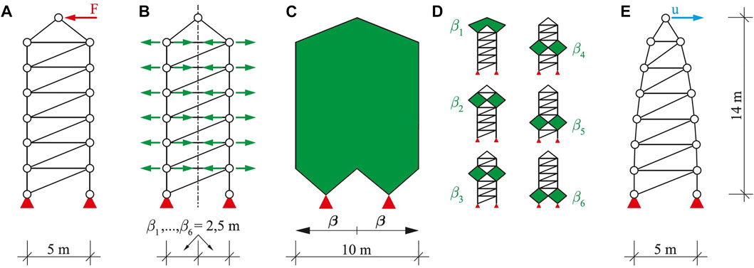
FIGURE 6. (A) Parametric model of an active truss with jointed connections, loading and support conditions, (B) horizontally variable nodes with symmetrical dependency, (C) design space Ω, (D) isolated parameters β, and (E) result of structural optimization of Γ operator (Figure 1A) and (Table 1).
For the comparative analysis, state-of-the-art algorithms available within the application GOAT (Figure 3) are used. In order to mitigate certain initial value dependencies of the algorithms, the optimization procedures are performed for different starting vectors β0 for each algorithm (Table 1). Within the range between 0.25 and 5.0 m, five initial vectors are selected. Since the metaheuristic algorithm CRS2 (GE) exhibits an inherent randomness for finding the global optimum, these optimizations are performed five times each. Thus, the best (GE*) and worst (GE’) results of these runs are noted in Table 1. To evaluate the efficiency of the derived structural optimization algorithm Γ, the results of the comparative analysis in Table 1 are examined. This way, an efficient and reliable algorithm that can be used for the derived method should be found. Hence, for each selected initial value β0, the maximal run-time is employed as early stop criterion and set to the respective time required by the Γ operator. This emphasizes the focus on the efficiency of the proposed algorithm Γ.
In Table 1, the optimized parameters β set by the algorithms can be observed. Furthermore, the deformations of the tip point d and the masses m of the resulting structures can be compared. Observing these results, one can identify that the proposed algorithm Γ is able to find the best solution with a deformation of d = 0.1515 cm. The corresponding initial parameter vector is selected as β0 = (1.25 1.25 1.25 1.25 1.25 1.25)T. The structural geometry corresponding to the attained result is shown in Figure 6E. For the remaining initial values, the neighboring solutions very close to the best solution are found by the derived Γ operator. The Subplex (NM) and the global evolutionary CRS2 (GE) algorithms calculate the same or an equivalent result for different examined five initial vectors β0. The remaining results of all algorithms are still useful, but worse compared to those found by the Γ operator. The local quadratic approximation (LQA) determines a deformation of d = 0.7563 cm for β0 = (0.25 0.25 0.25 0.25 0.25 0.25)T. This value represents the largest deviation from the optimum determined by Γ within the scope of this example. It should be noted that the CRS2 algorithm has a large spread in its results for different runs due to its inherent randomness. This dispersion of result values becomes obvious when comparing the results GE* and GE’.
In summary, this analysis could confirm that the Γ operator (Figure 1A) of the hierarchical method achieves the most favorable results compared to some state-of-the-art optimization algorithms. Moreover, it is possible to prove the higher efficiency of the Γ operator compared to the other optimization algorithms in the context of this structural example. As the available state-of-the-art algorithms are not able to achieve equivalent or better results within the same or shorter time for each chosen initial value, the Γ operator is regarded as the most reliable and efficient one for this example. Like within the investigations on the plausibility of the χ operator, these studies do not aim to prove that the proposed algorithm is able to find the global optimum for all cases of structural possibilities; rather, the reliability and efficiency of the presented operators should be emphasized. Since the complexity of the example presented in Section 4.3 is comparable to the one presented in this section, the results of the investigations are considered to be adequately useful for validation purposes in the framework of this study. In order to be able to perform a validation of the results of both operators for this example and thus to better relate the results to those of the following section, an optimal actuator placement is performed for the optimized structural geometry (Figure 6E). The results of the stepwise actuator placement are depicted in Figure 7. Observing the results of this example, it is noticeable that the algorithm prefers the actuator positions at the supports. However, in contrast to the result of the stepwise actuator placement for the Michell truss, there is no symmetrical actuator set chosen by the algorithm. This may be due to the fact that this structure itself is not symmetrical and has fewer force flow-oriented members. Hence, this observation does not make the results implausible. The actuator placement of all 26 actuators results in an evenly distributed actuator set, where the left flanks and horizontal braces are chosen to be compression actuators. The right flanks and diagonal braces are chosen to be tension actuators. The resulting transformed structure is polygonal. In addition, more detailed results regarding the stepwise actuator placement for the structure in Figure 6E can be found in the comparative bar chart (Figure 12) in Section 4.4. Here, the results are compared with those of the active hybrid structure derived in the following section.
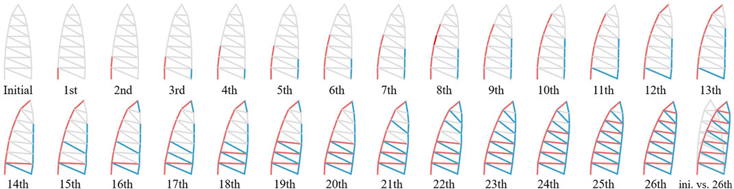
FIGURE 7. Stepwise process of choice for the placement of 26 actuators by operator χ (Figure 12).
4.3 Efficient Derivation of an Active Hybrid Structure
In Figure 8A, the parametric model of a multistory frame with a conical roof is depicted. This structure will serve as a sample to derive an active hybrid structure with the presented hierarchical method. As depicted in the example in Figure 6A, it is 14 m high and 5 m wide. The support conditions are fixed in all translational degrees of freedom, whereas they are regarded as free with respect to the rotations. Over its height, the structure is divided equally by seven horizontal rods. For all members, full circle cross sections with a diameter of 5 cm are selected. The material is chosen to be glass fiber reinforced plastic (GFRP) as this material is suitable for bending active structures. Due to validation purposes, mainly single-objective optimizations are performed for each operator of the method in the framework of these investigations (Eq. 25). As shown in Section 4.2, the investigated optimization problem is unconstrained. A horizontal force, as depicted in Figure 8A, serves as loading condition for the structural optimization. Again, the symmetric horizontal node displacements of the non-supported and non-loaded nodes on each level (Figure 8B,D) are chosen to be the variables
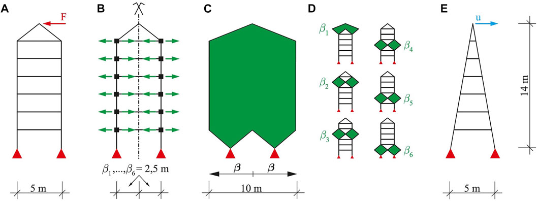
FIGURE 8. (A) Parametric model with loading and support conditions, (B) horizontally variable nodes with symmetrical dependency (visualized for β0 = (2.5 2.5 2.5 2.5 2.5 2.5)T), (C) design space Ω, (D) isolated parameters β, and (E) result of structural optimization γ (Figure 1A and Table 2).
For the subsequent investigations on an optimal actuator placement, the support conditions are considered fixed for all degrees of freedom as a transformation based on bending is desired. Therefore, in addition, the ratio of bending stresses to normal stresses is observed. This analysis results in a minimum value of 1%, a mean value of 59%, and a maximal value of 87%. These three representative terms of the outer chords of the structure are summed up in the target criterion f4 (Eq. 10) among others. It can be concluded that significant bending stresses also arise in parts of the structure. One reason for this is the restrictions that underlie the definition of the parametric model since the limits of the variables restrict the shape of the possible structural variants, which in total describe the solution space Ω. The present solution space does not contain structural variants corresponding to the formation criteria of trusses as no triangular geometries can occur within all variants of structures. Moreover, the node connections of all structural possibilities are imposed as rigid. It is obvious that within this example, the initial definition of the constraints of the connections, which are defined as not variable, has a significant influence on the later result. This restriction of the solution space also denies requirements of lightweight construction since bending stresses can be transferred via these connections. Likewise, the essential influences resulting from support conditions and rod arrangements, which can considerably affect the result, become evident. In the scope of this investigation, these mentioned effects are desired as the aim is to generate active hybrid structures in the field between lightweight construction and active bending. For a more comprehensive investigation, these parameters could also be included as variables in the parametric model and additionally submitted to the operator Γ by the vector β.
As indicated in Section 4.2, the performance of this optimized structure is compared with that of the optimization algorithms available within the software GOAT (Figure 3). Simultaneously, the efficiency of the derived Γ algorithm should be proven. Hence, for the comparative analysis performed in Table 2, the respective time required by the Γ operator is assigned as the reference. Therefore, all examined GOAT algorithms are allocated this respective reference time as early stop criterion, as shown already in Section 4.2. The analyses are performed for the same five initial parameter vectors β0. Observing the results of these comparative optimization runs in Table 2, it can be seen that the implemented Γ algorithm finds the best result of d = 0.3714 m for all examined starting vectors β0. The structural geometry corresponding to this result is depicted in Figure 8E. The global evolutionary algorithm (GE) is able to achieve an equal result only for the initial vectors of β0 = (0.25 0.25 0.25 0.25 0.25 0.25)T and β0 = (5 5 5 5 5 5)T in the best one of its five runs (see (GE*) in Table 2). As for the other runs of the evolutionary algorithm (GE), the remaining GOAT algorithms lead to significantly worse results with regard to the targeted criteria deformation. In particular, the local quadratic approximation BOBYQA (LQA), the local linear approximation COBYLA (LLA), and the Nelder–Mead SUBPLEX (NM) exhibit a large deviation of more than d = 347 cm for the initial vector of β0 = (5 5 5 5 5 5)T.
For the initial vector β0 = (2.5 2.5 2.5 2.5 2.5 2.5)T, the results of all algorithms are plotted in Figure 9A,C. Here, a comparative full enumeration of the solution space of structural variants that can be generated by the parametric model (Figure 8) is included. For the calculation of this data cloud, the whole parameter ranges are subdivided into five equal intervals first (light green). Afterward, the parameter intervals containing the optimal solution are refined by subdividing them into two intervals each (dark green). This procedure has to be chosen in order to enable the comparability of the solution γ found by Γ to the remaining potential structural variants. Therefore, the possible amount of subdivisions is limited by the computation time. Observing Figure 9A,C, it is noticeable that the highlighted results of the analysis noted in Table 2 still perform relatively well. Moreover, the complexity of the structural part of the overall hierarchical optimization problem becomes obvious.
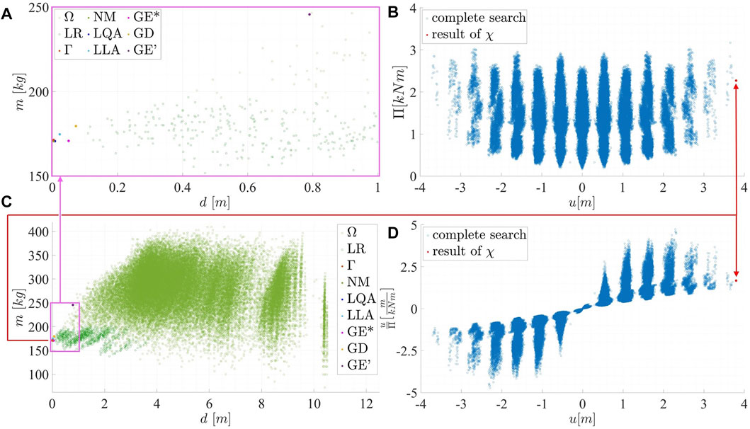
FIGURE 9. (A) and (C) Comparison and validation of the results of the structural optimizations using different algorithms (Table 2) for β0 = (2.5 2.5 2.5 2.5 2.5 2.5)T; (B) and (D) χ—optimal actuator placement, with the results of the respective complete enumerations (all structural variants Ω of the parametric model with local refinement LR (green circles), mass (Eq. 6) over deformation (Eq. 5)/complete search for 10 compression and 10 tension actuators (blue circles), (B) energy (Eq. 13) over transformation (Eq. 12), and (D)) efficiency (Eq. 18) over transformation (Eq. 12).
As none of the GOAT algorithms are able to find usable results for all chosen initial vectors within the limited computation time, these algorithms seem to be less suitable for structural optimizations of active hybrid structures, especially if the partially very large deviations are taken into account. This is why we proposed to employ the presented Γ algorithm instead. The resulting optimized structure γ, which is shown in Figure 8E, corresponds to the so-called Fin Ray® effect (Michel et al., 2008). Its bionic principle is well known as a compliant mechanism with an actuation by means of a support displacement.
This structure is subsequently passed to the operator χ in order to conduct an appropriate actuator placement according to the procedure depicted in Figure 1B. Therefore, the target criterion f6 is aimed as a maximal transformation in the horizontal direction indicated by the blue arrow in Figure 8E should be maximized. Figure 10A illustrates the stepwise choice of the operator χ for the placement of q = 14 actuators. The stroke is prescribed with s = 10 cm for this example.The remaining possible placements have nearly no more significant influence on the transformation but consume much more energy (Figure 12). In Figure 10A, the criterion of the curvature f5 = κ can be seen for each step. In contrast to the polygonal results of the active truss example (Figure 7), the resulting active hybrid structure is homogeneously curved. In addition, the values of criteria f1 (horizontal stiffness), f3 (frequency), f7 (energy), and f8 (efficiency) are observed during each step of the operator χ while determining the respective actuator set. These values are depicted in a net-diagram in Figure 10B for the initial structure and four exemplary steps. Therefore, the axes of the diagram are scaled in a way that the maximal value occurring for the respective criterion is plotted at 90% of the axis length. Simultaneously, the minimal value is attached at 10% of the axis length if it differed from zero. The intermediate values are interpolated linearly. The corresponding values for all steps g are contained in Figure 10C as the percentage of the maximum of the respective criterion. Evaluating the criteria values given in Figure 10B,C, it can be seen that the transformation increases, whereas the required energy does not steadily rise in every step for an increasing number of actuators placed. The largest efficiency can be observed for the placement of seven actuators. The maximal horizontal stiffness of the system results from the placement of two actuators. Observing the first eigenfrequency, one recognizes that there is no significant change initially. In the majority of cases, it rises due to the placement of tension actuators and decreases as a result of placements of compression actuators. For more than 14 actuators, it rises steadily up to a larger value compared to that of the initial structure. Here, the influence of the transformation can be detected. If a certain development of these criteria is intended, this can be achieved by alternating the weightings w in order to attain a specific behavior of the desired active hybrid structure. In order to verify the results obtained by the two successive methods Γ and χ, complete enumerations are conducted as part of this study (Figure 9). This comparison of solutions demonstrates that the results found using the hierarchical method proposed in Section 3 are optimal within the framework of the accuracy of the chosen discretization. In addition to the complete enumeration of the structural variants of Ω, a full investigation of the corresponding actuation concept is performed for the optimal structure γ exemplarily. Therefore, actuator sets consisting of ten tension and ten compression actuators are examined due to a limited computation time. Furthermore, the mapping between the corresponding results of the introduced operators Γ and χ, which is performed by the composition as indicated by Eq. 28, can be seen (red arrow in Figure 9). In addition, the enormous potential concerning the saving of computation time becomes obvious. Using the proposed procedure, not all 46,655 solutions of the domain Ω, that are represented by green circles in this plot, need to be determined in order to find the optimal solution found by the operator Γ in only a few loops e. This optimization result is highlighted as the red dot in Figure 9A,C. Regarding the actuator placement conducted by the operator χ, it becomes obvious that due to the stepwise procedure depicted in Figure 1B, it is possible to directly deduce suitable positions for the choice of g = 1,…, q actuators for the optimal structure γ previously determined by the hierarchical structural optimization conducted by the operator Γ. This prevents the need to examine all 184,756 possible actuator sets (Figure 9B,D), particularly regarding the target criteria energy over transformation (Figure 9B) and regarding the target criteria efficiency over transformation (Figure 9D). The efficiency of the proposed hierarchical method becomes especially obvious, regarding the fact that a corresponding actuator placement has to be conducted for all possible structural variants Ω in order to determine an optimal active hybrid structure. Therefore, the total number of combinatorially possible actuator placements (consisting of ten compression and ten tension actuators) for all possible structural variants would be nearly nine billion, even for such a rather simple structure.
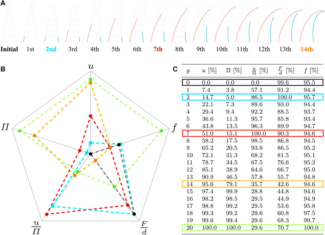
FIGURE 10. (A) Stepwise process of choice for the placement of 14 actuators by operator χ, observed criteria values for transformation u, energy Π, efficiency
As the attained results are regarded as sufficient, no further loops i of the developed method are performed within the scope of these investigations. Hence, as n = 1, Ψ = ρ1 represents the solution for the active hybrid structure regarding the predefined weighting w, parameters β, and number of actuators q according to Eq. 26.
In the following, the resulting actuator placements conducted by the operator χ according to the target criterion f5 = κ are presented and compared to the eigenforms of the structure, which, in addition, correspond to the target criterion f3 = ω. This points out the relation between the single target criteria of χ and Γ. The corresponding results are depicted in Figure 11A and can be compared to the respective eigenforms of the structure γ, which are displayed in Figure 11B. Therefore, the target criterion κ is adapted to consider the curvature of the right outer chord only. This also demonstrates that the proposed procedure can also be adjusted with respect to specific regions of the structure. For a choice of q = 7 actuators on the right outer chord, according to the target criterion fw,I = κ, a similarity to the first eigenform of the structure can be observed. Furthermore, it becomes obvious that a related transformation shape can be achieved by different actuator sets as the transformation shape resulting from this actuation is very much alike to that depicted for the last transformation step in Figure 10A. As a difference, only tension actuators are employed for the aforementioned solution. By choosing q = 14 actuators on the two outer chords for the modified target criterion of the undirected curvature
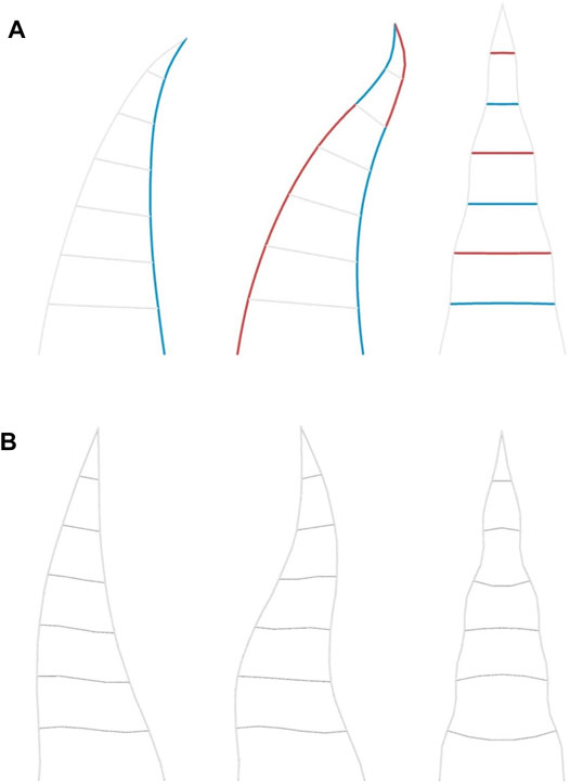
FIGURE 11. (A) Results of operator χ for curvature of right outer chord for target criteria: fw,I = κ for placement of q = 7 actuators on right chord (left);
In conclusion, this comparative analysis has emphasized the decisive influence of the variation of the target criteria and its formulation on the design of active hybrid structures.
4.4 Discussion of Results
Finally, this section compares the analyses results of all selected actuator sets of the active truss structure (Figure 6E) derived with the presented methodology (Figure 1C) with that of the active hybrid structure (Figure 8E) also designed with the introduced method. Furthermore, some open questions raised by these studies will be discussed. In the bar charts in Figure 12, the absolute result values of the heuristic actuator placements for the structures from Figure 6E and Figure 8E are compared. Here, some differences are particularly noticeable. With the placement of 12 actuators, the active hybrid structure already achieves a larger transformation than the active truss variant with the placement of 26 actuators. While in the active truss variant the energy consumption increases slightly from actuator set to actuator set, in the active hybrid structure, this energy consumption increases over-proportionally up to the placement of the 15th actuator. Studying the efficiency values, it is noticeable that the values for the active hybrid structure are relatively high up to the ninth actuator set. This means that with the first–ninth actuator sets, actuation of the active hybrid structure can partially be twice as efficient as for the active truss. Obviously, the stiffness values for the diagonally braced active truss structure are much higher, although it should also be mentioned here that the shape of the initial structures (Figure 6E and Figure 8E) differ and that additional truss members are inserted into the active truss, which also leads to a comparatively higher mass of the active truss structure. The stiffness values change slightly during the analysis. While a modest increase in stiffness can be observed in the actuator analysis of the active truss structure, a slight alteration can be noticed in that of the active hybrid structure. In summary, the values for transformability (Eq. 12) and energy efficiency (Eq. 18) of the active hybrid structure variant proved to be particularly promising, while structural stiffness (Eq. 5) can be mentioned as a distinct advantage of the active truss structure. However, the active truss structure analyzed in this study is also designed with a higher mass (Eq. 6).
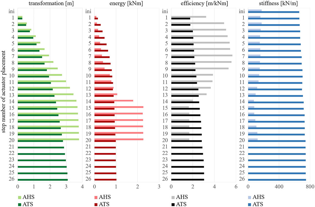
FIGURE 12. Bar chart comparison of result values of stepwise heuristic actuator placement with operator χ for active truss structure (ATS) (Figure 6E) (dark bar charts) vs for active hybrid structure (AHS) (Figure 8E) (light bar charts); for criteria values, transformation (green) (Eq. 12), energy (red) (Eq. 13), efficiency (black) (Eq. 18), and stiffness (blue) (Eq. 5).
In addition to these comparisons based on pure result performance in numbers, the fact that very different transformation shapes are obtained should also be mentioned. On the one hand, this is due to the different initial geometry, but on the other hand, it is also caused by the fact that the truss has jointed connections, which on the one hand leads to a polygonal transformation shape, and on the other hand could result in more maintenance of the jointed connections in real load-bearing structures. If the realization of these structures is considered from a cost-effectiveness perspective, it can be concluded in the framework of these studies that, with regard to the actuators, which are associated with high costs according to the current state of the art, a larger transformation can be achieved for the observed active hybrid structure variant with fewer actuators than for the active truss structure. A potential reduction in actuator costs can be identified in this respect, which might represent an advantage of active hybrid structures.
5 Conclusion
Within the framework of these studies, a systematic process for conducting the novel task of designing active hybrid structures is proposed. Therefore, appropriate target criteria and a hierarchical method (Figure 1C) are derived. This presented methodology allows an effective derivation of such structures with respect to objectives from the field of lightweight construction, active bending, and active structural control. Thus, the resulting structures are resource-efficient. The structural optimization step Γ (Figure 1A) can reach a reduction in material consumption. Furthermore, an energy-efficient actuation can be achieved by employing a subsequent actuator placement conducted by the operator χ (Figure 1B). Nevertheless, these structures can also exhibit a high degree of adaptability by involving active bending. Moreover, it enables a realization with only a few actuators. Considering the current state of actuator technology, this is preferable for ecological and economic reasons, but also regarding the characteristic of elegant transformation shapes. Within the presented method, the mentioned approaches can be balanced by the introduced weightings of the proposed target criteria that correspond to the respective fields. Furthermore, a mathematical description of the whole method is presented. It is supplemented by program flowcharts pointing out the procedures conducted by the operators Γ and χ. These two derived partial methods incorporate hierarchical and heuristic methods in order to solve the posed search problem more efficiently as not the entire domain has to be analyzed. Moreover, within the context of these investigations, a selection of standard optimization algorithms is compared to the derived structural optimization algorithm. Concerning the examined structures, the proposed operator Γ convinces regarding its performance. The actuator placement method χ is verified using the well-known Michell structure, which is derived by trajectory lines. In addition, complete enumerations are used to visualize the performance of the different optimization algorithms regarding their efficiency (Figure 9) as no analytical solution for the proof of a global optimum is available. In the comparative study (Figure 12), considerable potentials of an active hybrid structure in terms of transformability and energy-efficient actuation are identified. This highlights that the intention of these studies is not necessarily that structures should be equipped with a high number of actuators. This holds especially considering the current actuator technology with respect to costs but also concerning maintenance and environmental compatibility. Rather, these studies are intended to provide insights into the potential benefits of optimal actuator placement within the design process of active hybrid structures. However, if actuator technology should evolve in the future, the results of these studies can provide a good basis for structures that use flexible component behavior and several integrated actuators to ensure a high adaptability. This study primarily contributes toward facilitating the realization of innovative structural solutions in the future by means of modern and efficient design processes.
Regarding the future developments, further structural optimization operators based on topology or BESO optimization could be investigated in combination with the presented optimal actuator placement algorithm χ, instead of the introduced operator Γ. By doing so, the initial definition of a parametric model could become unnecessary, and the method could be launched in a free design space. The actuator placement method χ could also be further developed. Such an enhancement could be realized, for example, by allowing the selection of multiple actuators within one step g or a deselection of formerly chosen actuators that have become inefficient in later steps. As a result, the presented method for actuator placement might become more efficient or the quality of the results may improve. This could also be advantageous, especially for more complex structural geometries. In addition, we will validate the results on a prototype (Figure 13 (Bleicher et al., 2021)). Hence, studies on optimal actuator placement for a 3D structure have to be conducted. In this way, the algorithm could be further investigated regarding its suitability for real-world applications. Consequently, further studies could also elaborate in terms of more accurate approximations of the structural models used for the analysis. This could then be followed by prototype investigations on the energy efficiency of different actuation concepts and for active vibration control (Jirasek et al., 2019; Jirasek et al., 2020). Thus, additional studies could be conducted to determine whether integrated actuators or actuation at the supports are advantageous. In context of further validations, additional optimizations regarding other target criteria or different combinations of those should be performed. Hence, the suitability of the method for many objectives could be verified. In this way, a further contribution to the improvement of the design method for active hybrid structures may be achieved. A further goal could also be to optimize the structural geometry and the placement of the actuators simultaneously, instead of using iterative loops of hierarchical operators. This could allow balancing the initial priority of structural optimization and the actuator placement. Nevertheless, a more complex optimization problem would have to be solved in that case.
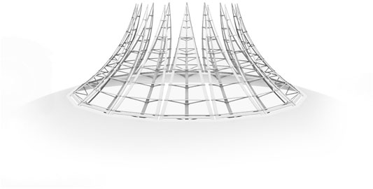
FIGURE 13. Study of an active hybrid roof structure at the BTU as part of preliminary investigations for prototyping.
Data Availability Statement
The original articles presented in the study are included exclusively in the article, further inquiries can be addressed to the corresponding author.
Author Contributions
PM: Conceptualization, Methodology, Software, Formal analysis, Investigation, Writing - Original Draft, Writing - Review & Editing, Visualization. AB: Conceptualization, Resources, Writing - Review & Editing, Supervision, Project administration, Funding acquisition.
Funding
This study was funded by the Brandenburg University of Technology Cottbus – Senftenberg.
Conflict of Interest
The authors declare that the research was conducted in the absence of any commercial or financial relationships that could be construed as a potential conflict of interest.
Publisher’s Note
All claims expressed in this article are solely those of the authors and do not necessarily represent those of their affiliated organizations, or those of the publisher, the editors, and the reviewers. Any product that may be evaluated in this article, or claim that may be made by its manufacturer, is not guaranteed or endorsed by the publisher.
References
Ballas, R. G. (2007). Piezoelectric Multilayer Beam Bending Actuators: Static and Dynamic Behavior and Aspects of Sensor integrationMicrotechnology and MEMS. Berlin and New York: Springer.
Bleicher, A., Schauer, T., Jirasek, R., Höltke, T., Zhang, Y., Marker, P., et al. (2021). Hybride Konstruktionen an der BTU Cottbus‐Senftenberg. Bautechnik 98, 907–920. doi:10.1002/bate.202100056
Bleicher, A., Schlaich, M., Fujino, Y., and Schauer, T. (2011). Model-based Design and Experimental Validation of Active Vibration Control for a Stress Ribbon Bridge Using Pneumatic Muscle Actuators. Eng. Structures 33, 2237–2247. doi:10.1016/j.engstruct.2011.02.035
Crisfield, M. A. (1997). Non-linear Finite Element Analysis of Solids and Structures, 2. Chichester: Wiley.
Crisfield, M. A. (2003). Non-linear Finite Element Analysis of Solids and Structures, 1. Chichester: Wiley. reprinted. edn.
Engels, H., Becker, W., and Morris, A. (2004). Implementation of a Multi-Level Optimisation Methodology within the E-Design of a Blended wing Body. Aerospace Sci. Technology 8, 145–153. doi:10.1016/j.ast.2003.10.001
Geiger, F., Gade, J., von Scheven, M., and Bischoff, M. (2020). A Case Study on Design and Optimization of Adaptive Civil Structures. Front. Built Environ. 6, 94. doi:10.3389/fbuil.2020.00094
Guo, B., Karaca, O., Summers, T., and Kamgarpour, M. (2020). Actuator Placement under Structural Controllability Using Forward and Reverse Greedy Algorithms. arXiv:1912.05149 [math] ArXiv: 1912.05149.
Ham, R., Sugar, T., Vanderborght, B., Hollander, K., and Lefeber, D. (2009). Compliant Actuator Designs. IEEE Robot. Automat. Mag. 16, 81–94. doi:10.1109/MRA.2009.933629
Heidingsfeld, M., Rapp, P., Böhm, M., and Sawodny, O. (2017). “Gramian-based Actuator Placement with Spillover Reduction for Active Damping of Adaptive Structures,” in 2017 IEEE International Conference on Advanced Intelligent Mechatronics (Munich, Germany: AIM), 904–909. doi:10.1109/AIM.2017.8014133
Jirasek, R., Schauer, T., and Bleicher, A. (2019). Active Vibration Control of a Convertible Structure Based on a Linear Parameter-Varying Model. IFAC-PapersOnLine 52, 190–195. doi:10.1016/j.ifacol.2019.12.375
Jirasek, R., Schauer, T., and Bleicher, A. (2020). Active Vibration Control of a Convertible Structure Based on a Polytopic LPV Model Representation. IFAC-PapersOnLine 53, 8389–8394. doi:10.1016/j.ifacol.2020.12.1590
Jungnickel, D. (1999). Graphs, Networks, and Algorithms. Berlin; New York: Springer. OCLC: 655831753.
Kaelo, P., and Ali, M. M. (2006). Some Variants of the Controlled Random Search Algorithm for Global Optimization. J. Optim Theor. Appl 130, 253–264. doi:10.1007/s10957-006-9101-0
Lienhard, J., and Gengnagel, C. (2018). “Recent Developments in Bending-Active Structures,” in IASS Annual Symposium 2018 – Creativity in Structural Design (International Association for Shell and Spatial Structures (IASS)).
L. L. Howell, S. P. Magleby, and B. M. Olsen (Editors) (2013). Handbook of Compliant Mechanisms (Chichester: Wiley). doi:10.1002/9781118516485
Loos, C., Krause, S., and Hasenauer, J. (2018). Hierarchical Optimization for the Efficient Parametrization of ODE Models. Bioinformatics 34, 4266–4273. doi:10.1093/bioinformatics/bty514
Manohar, K., Kutz, J. N., and Brunton, S. L. (2020). Optimal Sensor and Actuator Selection Using Balanced Model Reduction. arXiv:1812.01574 [cs, math] ArXiv: 1812.01574.
Marker, P., Stammen, L., and Bleicher, A. (2019). “Energy-efficient Actuator Placement for a Convertible Bending-Active Structure,” in IASS Annual Symposium 2019 – Structural Membranes 2019, Form and Force (Barcelona, Spain: International Association for Shell and Spatial Structures IASS).
McNeel, R. (2018). Rhinoceros 6 - Design, Model, Present, Analyse, Realize - Robert McNeel and Associates. Availableat: https://www.rhino3d.com/de/.
Michel, S., Jordi, C., Wahl, L., Widmer, N., Fink, E., Kniese, L., et al. (2008). “Biomimetics in Airship Design,” in 19th International Conference on Adaptive Structures and Technologies, 1–21.
Michell, A. G. M. (1904). Lviii. The Limits of Economy of Material in Frame-Structures. Lond. Edinb. Dublin Philosophical Mag. J. Sci. 8, 589–597. doi:10.1080/14786440409463229
Microsoft (2019). Visual Studio 2019. Availableat: https://visualstudio.microsoft.com/de/.
Otto, F., and Burkhardt, B. (1972). IL Five: Convertible Roofs. Information of the Institute for Lightweight Structures Series (George Wittenborn Incorporated.
Powell (1994). Advances in Optimization and Numerical Analysis. Dordrecht, Netherlands: Springer Netherlands. doi:10.1007/978-94-015-8330-5
Powell, M. J. D. (2009). The BOBYQA Algorithm for Bound Constrained Optimization without Derivatives, 39.
Prabhu, P., MuralidharaVeeresha, R. K., Veeresha, R. K., and Venugopal, T. R. (2021). Design, Fabrication, and Testing of Flexurally Amplified Piezo Actuator. Mater. Today Proc. 46, 9490–9497. doi:10.1016/j.matpr.2020.03.502
Preisinger, C. (2018). Karamba3D 1.3.1. Availableat: https://www.karamba3d.com/.
Rechenraum GmbH (2021). GOAT. Availableat: https://www.rechenraum.com/en/goat.html.
Reksowardojo, A. P., Senatore, G., and Smith, I. F. C. (2019). Experimental Testing of a Small-Scale Truss Beam that Adapts to Loads through Large Shape Changes. Front. Built Environ. 5. doi:10.3389/fbuil.2019.00093
Rodrigues, H., Guedes, J. M., and Bendsoe, M. P. (2002). Hierarchical Optimization of Material and Structure. Struct. Multidisciplinary Optimization 24, 1–10. doi:10.1007/s00158-002-0209-z
Rowan, T. H. (1990). Functional Stability Analysis of Numerical Algorithms. Austin, Texas, USA: The University of Texas at Austin. Ph.D. thesis.
Rubin, H., and Schneider, K.-J. (2002). Baustatik - Theorie I. und II. Ordnung. Werner-Ingenieur- Texte (Düsseldorf: Werner), 4., neu bearbeitete und erweiterte. auflage edn.
Russell, S. J., and Norvig, P. (2016). Artificial Intelligence: A Modern approachAlways Learning (Boston and Columbus and Indianapolis: Pearson). third editionglobal edition edn.
Rutten, D. (2014). Grasshopper Version Build 1.0.0007, robert Mcneel and Associates. Availableat: https://www.grasshopper3d.com/. (Acessed on 05 12, 2017).
Sachse, R., and Bischoff, M. (2021). A Variational Formulation for Motion Design of Adaptive Compliant Structures. Int. J. Numer. Methods Eng. 122, 972–1000. doi:10.1002/nme.6570
Sachse, R., Geiger, F., von Scheven, M., and Bischoff, M. (2021). Motion Design with Efficient Actuator Placement for Adaptive Structures that Perform Large Deformations. Front. Built Environ. 7, 88. doi:10.3389/fbuil.2021.545962
Schleicher, S. (2015). Bio-inspired Compliant Mechanisms for Architectural Design. Stuttgart: University of Stuttgart. Dissertation.
Senatore, G., Duffour, P., and Winslow, P. (2018). Energy and Cost Assessment of Adaptive Structures: Case Studies. J. Struct. Eng. 144, 04018107. doi:10.1061/(ASCE)ST.1943-541X.0002075
Senatore, G., Duffour, P., and Winslow, P. (2019). Synthesis of Minimum Energy Adaptive Structures. Struct. Multidisc Optim 60, 849–877. doi:10.1007/s00158-019-02224-8
Senatore, G., and Reksowardojo, A. P. (2020). Force and Shape Control Strategies for Minimum Energy Adaptive Structures. Front. Built Environ. 6. doi:10.3389/fbuil.2020.00105
Sobek, W. (2016). Ultra-lightweight Construction. Int. J. Space Structures 31, 74–80. doi:10.1177/0266351116643246
Sobieszczanski-Sobieski, J., James, B. B., and Riley, M. F. (1987). Structural Sizing by Generalized, Multilevel Optimization. AIAA J. 25, 139–145. doi:10.2514/3.9593
SOFiSTiK AG (2018). SOFiSTiK 2018. Availableat: https://www.sofistik.de/.
Steffen, S., Weidner, S., Blandini, L., and Sobek, W. (2020). Using Influence Matrices as a Design and Analysis Tool for Adaptive Truss and Beam Structures. Front. Built Environ. 6, 83. doi:10.3389/fbuil.2020.00083
Tejani, G., Savsani, V., and Bureerat, S. (2018). Truss Topology Optimization: A Review: Past, Present, and Future. auflage edn. Vadodara, India: Saarbrücken: Scholars’ Press, 1.
Tenek, L. T., and Argyris, J. H. (1998). Finite Element Analysis for Composite Structuresof Solid Mechanics and its Applications, 59. Dordrecht: Kluwer Acad. Publ.
Wagner, J. L., Gade, J., Heidingsfeld, M., Geiger, F., von Scheven, M., Böhm, M., et al. (2018). On Steady-State Disturbance Compensability for Actuator Placement in Adaptive Structures. at - Automatisierungstechnik 66, 591–603. doi:10.1515/auto-2017-0099
Wagner, J. L., Gienger, A., Stein, C., Arnold, P., Tarín, C., Sawodny, O., et al. (2020). Optimal Static Load Compensation with Fault Tolerance in Nonlinear Adaptive Structures under Input and State Constraints. Front. Built Environ. 6. doi:10.3389/fbuil.2020.00093
Wang, Y., and Senatore, G. (2020). Minimum Energy Adaptive Structures - All-In-One Problem Formulation. Comput. Structures 236, 106266. doi:10.1016/j.compstruc.2020.106266
Wiedemann, J. (1996). Leichtbau: Band 2: Konstruktion. neubearbeitete auflage edn. Berlin: Springer, 2.
Yokoyama, R., Kamada, H., Shinano, Y., and Wakui, T. (2021). A Hierarchical Optimization Approach to Robust Design of Energy Supply Systems Based on a Mixed-Integer Linear Model. Energy 229, 120343. doi:10.1016/j.energy.2021.120343
Zeng, J., Huang, Z., Fan, K., and Wu, W. (2020). An Adaptive Hierarchical Optimization Approach for the Minimum Compliance Design of Variable Stiffness Laminates Using Lamination Parameters. Thin-Walled Structures 157, 107068. doi:10.1016/j.tws.2020.107068
Zhao, Y., Mei, J., Jin, Y., and Niu, W. (2021). A New Hierarchical Approach for the Optimal Design of a 5-dof Hybrid Serial-Parallel Kinematic Machine. Mechanism Machine Theor. 156, 104160. doi:10.1016/j.mechmachtheory.2020.104160
Nomenclature
β Vector containing the design parameters of the structure
fχ Vector of target criteria for actuator placement
fw,II Vector of weighted target criteria values for multi-criteria optimization
f Vector of target criteria
KE Elastic stiffness matrix
KG Geometrical stiffness matrix
KU Initial displacement stiffness matrix
K Nonlinear stiffness matrix
M Mass matrix
wχ Vector of weighting factors corresponding to target criteria for actuator placement
wΓ Vector of weighting factors corresponding to target criteria for structural optimization
w Vector of target criteria
χ Operator performing actuator placement
χ◦Γ Operation describing the successive execution of operator χ after operator Γ
Δh Absolute displacement in self-weight direction
Γ Operator performing structural optimization
γ Resulting structure of structural optimization performed by operator Γ
κ Curvature
Ω Design space for structural optimization
ω Circular eigenfrequency
Π Energy
Πkin Kinetic energy
ΠM Strain energy resulting from bending moments
ΠN Strain energy resulting from normal forces
Πpot Potential energy
Ψ Resulting optimized active hybrid structure
ρi Resulting optimized active hybrid structure of loop i of the whole method
σM Bending stress
σN Normal stress
ɛ Strain
ɛC,g,h Compressive strain load cases examined within the hth iteration in step g of operator χ
ɛT,g,h Tensional strain load cases examined within the hth iteration in step g of operator χ
A Cross-sectional area
ag Acceleration of gravity
Ag,h Set of all tension and compression actuators examined within the hth iteration in step g of operator χ
Ag Set of all tension and compression actuators chosen within step g of operator χ
b Number of evaluation points of stresses per rod
Cg,h Set of compression actuators examined within the hth iteration in step g of operator χ
d Deformation
d Index of the structural parameter currently varied by the operator Γ
E Young’s modulus
e Index of the current loop of operator Γ
F Applied force
f Eigenfrequency
f1 Target criterion: stiffness
f2 Target criterion: mass
f3 Target criterion: eigenfrequency
f4 Target criterion: relation of bending stresses to normal stresses
f5 Target criterion: curvature
f6 Target criterion: transformation
f7 Target criterion: energy
f8 Target criterion: energy efficiency of actuation
fw,I Weighted target criterion value for single-criterion optimization
g Index of the current loop of operator χ
H Number of possible combinations that have to be conducted within step g of operator χ
I Area moment of inertia
i Index of the current loop of the whole method
j Index of current rod
k Index of current evaluation point
l Length of rod
m Mass
n Total number of loops conducted by the whole method
nact Number of possible combinations without consideration of order
P Composite function describing the whole method
p Number of structural parameters
q Total number of actuators to be chosen by operator χ
Qg Actuator chosen in step g of operator χ
r Number of rods
RC,g,j Possible compression actuator at rod j to be evaluated in step g of operator χ
RT,g,j Possible tension actuator at rod j to be evaluated in step g of operator χ
s Stroke of actuators
Tg,h Set of tension actuators examined within the hth iteration in step g of operator χ
u Transformation
v Velocity
w(x) Deflection curve
w1 Weighting factor corresponding to target criterion: stiffness
w2 Weighting factor corresponding to target criterion: mass
w3 Weighting factor corresponding to target criterion: eigenfrequency
w4 Weighting factor corresponding to target criterion: relation of bending stresses to normal stresses
w5 Weighting factor corresponding to target criterion: curvature
w6 Weighting factor corresponding to target criterion: transformation
w7 Weighting factor corresponding to target criterion: energy
w8 Weighting factor corresponding to target criterion: energy efficiency of actuation
z Number of target criteria
Keywords: active hybrid structures, actuator placement, hierarchical optimization, lightweight construction, active bending, structural control
Citation: Marker P and Bleicher A (2022) A Hierarchical Optimization Method for the Design of Active Hybrid Structures. Front. Built Environ. 8:705434. doi: 10.3389/fbuil.2022.705434
Received: 05 May 2021; Accepted: 17 February 2022;
Published: 02 June 2022.
Edited by:
Vagelis Plevris, Qatar University, QatarReviewed by:
George D. Manolis, Aristotle University of Thessaloniki, GreeceSaid Elias Rahimi, University of Iceland, Iceland
Manolis S. Georgioudakis, National Technical University of Athens, Greece
Copyright © 2022 Marker and Bleicher. This is an open-access article distributed under the terms of the Creative Commons Attribution License (CC BY). The use, distribution or reproduction in other forums is permitted, provided the original author(s) and the copyright owner(s) are credited and that the original publication in this journal is cited, in accordance with accepted academic practice. No use, distribution or reproduction is permitted which does not comply with these terms.
*Correspondence: Paul Marker, ZmctaHlicmlkZS1rb25zdHJ1a3Rpb25lbi1tYXNzaXZiYXVAYi10dS5kZQ==