 Liang Xie
 Bin Tang
 Shaoqing Liu
 Yanxia Gong
 Xunchao Cheng1
- 1College of Civil Engineering and Architectural, Guilin University of Technology, Guilin, China
- 2WSGRI Engineering & Surveying Incorporation Limited, Wuhan, China
- 3Department of Civil Engineering, HuBei University of Technology Engineering and Technology College, Wuhan, China
The setting of the late poured band is an effective measure to control the differential settlement and the stress concentration of the foundation. However, the lag of the pouring time of the late poured band will also bring adverse effects to the construction process. Taking a large commercial complex as an example, Midas GTS NX finite element software is used for the overall foundation modeling, and the collaborative calculation of settlement is carried out by adjusting the composite foundation scheme. The calculation results of conventional codes are compared and analyzed, and the scheme is verified and optimized. Then, the variation value of differential settlement on both sides of the late poured band with loading is studied by simulating the graded loading of each area in the whole process of construction. By comparing the variation value of differential settlement and the calculation value of differential deformation that the stiffness of the late poured band can resist and the limit value of codes, the time node of late poured band pouring in advance can be obtained, and finally the influence of early pouring of the late poured band on the collaborative settlement of the foundation is verified and calculated. The results show that: the settlement calculation of finite element analysis is generally smaller than that of standard calculation; The settlement at the edge of the raft is small, and the settlement at the center of the raft and the places with large load is large; Considering the interaction of the whole raft and subgrade under the raft, this method can verify and optimize the design scheme of composite foundation and save the pouring time of the late poured band. The experience and achievements so made can be used as a reference for similar projects.
1 Introduction
In response to more diversified functional requirements in architecture, new buildings are mostly designed with high tower and low skirt building or pure basement. The large load difference between the main podium buildings results in a large difference between the foundation internal force and the foundation reaction force, and the differential settlement of the foundation is also large. In these large buildings, in order to adapt to the influence of environmental temperature changes, concrete shrinkage, structural uneven settlement and other factors, the late poured band with a certain width reserved in beams, slabs (including foundation slabs), walls and other structures and poured after a certain period of time can effectively reduce differential settlement and stress concentration. But the top-down late poured band may bring a series of adverse effects such as water accumulation in rainy days, corrosion of reserved steel bars, hidden dangers of the entrance, and extension of construction period. At present, a number of scholars (Roberts and Misra, 2009; Wang et al., 2012; Basuony et al., 2013; Zhang et al., 2019; Wang et al., 2021) have carried out research on differential settlement of foundation, and, in combination with different geological conditions and foundation design parameters, put forward a variety of design ideas of foundation, which center on settlement control supplemented by bearing capacity control, which has led to the research idea of optimizing the pouring time of late poured band. Li, (2019) summed up the provisions on the pouring time of the late poured band in the Chinese codes and regulations, concluded that the pouring time of late poured band should be mainly controlled by differential settlement.
Because of the differences in the plane shape, height and geological conditions of each building, the conventional theory and experimental research have their limitations. However, finite element analysis can solve these problems well by simulating various conditions and combining well-developed theoretical calculations. Taghavi Ghalesari and Janalizadeh Choobbasti, (2016), Halder and Manna, (2022), Deb and Pal, (2022), all effectively analyzed the differential settlement of foundation in combination with finite element calculation software, which well verified the applicability of finite element calculation in the study of differential settlement of building complexes. Ye and Chi, (2011) took a comprehensive building with an integral basement connecting five towers as an example, calculated the maximum settlement of the foundation before the fill of the late poured band and the maximum settlement after the topping out (completion of roof concrete pouring) of the structure with the fill of the late poured band under a certain working condition. The difference between the two settlement values was within the code requirements, thus the conclusion that the late poured band could be filled under the working condition was obtained. Zhao et al. (2012) analyzed the settlement of the foundation before and after the fill of the late poured band, and concluded that pile-raft foundation settlement generates minute difference (less than 5%) after the fill of the late poured band. Wang et al. (2014) discussed the variation law of differential settlement under three working conditions by assuming that the late poured band is filled when the main building is constructed to 10F(Floor), 15F, and 20F. Yuanming and Qinnan (2017) studied the differential settlement of the foundation under the three working conditions of 0F, 2F, and 4F that the skirt building has been constructed through simulation calculation by simplifying the construction sequence, and concluded that the late poured band can be filled after the skirt building is constructed to 0F. Zhu et al. (2017) modeled the main building and skirt building separately, and obtained the settlement contour diagram of their foundation plates through simulation calculation. After comparing with the control requirements for differential settlement in the codes, they proposed the pouring time of late poured band. Jiang et al. (2019) studied the stress development during the construction period of the concrete under different spacing of the late poured band with finite element method (FEM). Jia et al. (2022) studied the effect of the quantity and the pouring time of late poured band on the temperature stress of the structure with a spatial non-linear simulation analysis program, and concluded that the pouring time of the late poured band should be determined according to the temperature stress analysis and the specific construction conditions.
These research results on the pouring time of late poured band confirm the research idea of using finite element software to calculate differential settlement and optimize the pouring time of late poured band, but there is generally no comparative analysis on the difference between the code method calculation and finite element calculation of foundation scheme, and no finite element calculation is used to research the feasibility and optimization of the scheme before the analysis of the pouring time. The finite element calculation of the differential settlement on both sides of the late poured band is just directly carried out and the conclusion of the pouring time is obtained, which lacks the precondition for the optimization research. In the control conditions of pouring time, only the limit value of differential settlement in the codes is considered, the differential deformation that the stiffness of the late poured band can resist is ignored, that is, the failure of the late poured band due to its insufficient stiffness under the condition that it meets the requirements of the codes is ignored, the control conditions for optimization research are insufficient. After the analysis and determination of the time for advance pouring of the late poured band, the verification and calculation of the influence of the advanced pouring on the collaborative settlement of the foundation and subgrade is not carried out, there are certain risks in engineering application.
In this paper, in order to realize the optimization study of pouring time of late poured band, the finite element software Midas GTS NX is used to model the natural subgrade, CFG (Cement Fly-ash Gravel) pile composite foundation, reinforced concrete uplift pile and large raft foundation with different thickness in different areas, calculate and verify the feasibility of the foundation scheme, and the settlement trial calculation is carried out by adjusting the pile spacing and pile length of CFG pile to realize the settlement coordination of the foundation and subgrade and the optimization of the foundation scheme. By simulating the step-by-step loading process in each area during construction, the differential settlement on both sides of the late poured band is calculated. As long as the differential settlement approaches a controllable value by considering the double control conditions of the stiffness of the late poured band itself and the limit value of the differential settlement in the codes, the late poured band can be filled a certain amount of time before the completion of construction of the adjacent buildings, and the overall model calculation after the fill of the late poured band is carried out to verify its feasibility.
2 Engineering and geological survey
2.1 Project overview
The project is located in Beijing, with a total construction area of about 175,000 m2. The architectural complex consists of six single buildings. The relevant architectural design parameters are shown in Table 1, and the layout of each single building is shown in Figure 1.
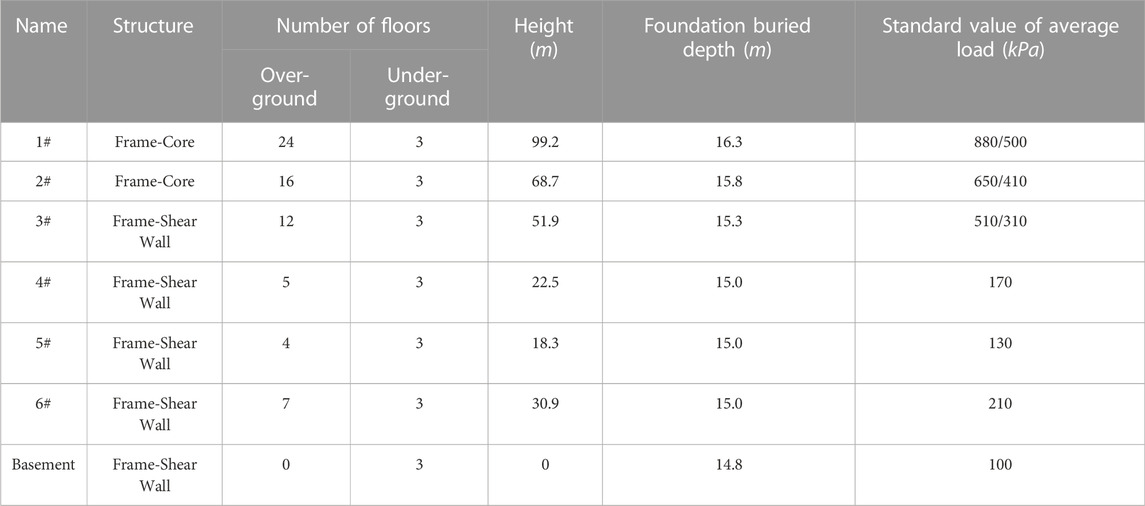
TABLE 1. Architectural design parameters.
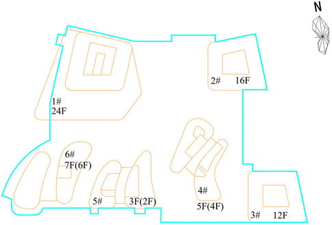
FIGURE 1. Single building plane layout.
2.2 Geological conditions
In terms of geomorphic unit, the engineering site belongs to the middle and lower part of alluvial fan of Wenyu River. According to sedimentary age and genetic type, the soil layer in the site can be divided into two categories: artificial accumulation layer and Quaternary sedimentary layer. The main physical and mechanical indexes of soil layer in the site are shown in Table 2.
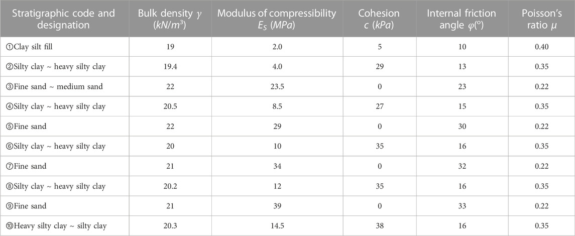
TABLE 2. Main physical and mechanical indexes of soil layer.
3 Collaborative analysis of subgrade and foundation
3.1 Preliminary foundation scheme analysis
The soil layer under the foundation of the project is relatively weak and prone to subsidence, the superstructure load distributed on the same foundation slab is quite different, and the pressure difference transmitted to the same foundation slab is nearly 780 kPa. According to the load conditions of each building structure, the preliminary foundation scheme designed according to Chinese Codes is as follows:
(1) Building 1#∼3#: Since the natural foundation cannot meet the requirements of foundation bearing capacity and deformation, CFG pile composite foundation is adopted. CFG is concrete pile without reinforcement, mainly used for vertical bearing. The foundation adopts flat raft foundation.
(2) Buildings 4#∼6# and basement: the soil layer ④ silty clay or ⑤ fine sand are taken as bearing layer of the foundation in form of beam-slab raft. See Figure 2 for the thickness of foundation slab in each area. The uplift pile is reinforced concrete pile, and the lateral friction between the pile and soil is increased by injecting cement slurry around the pile to achieve vertical uplift resistance. The diameter of the uplift pile is 600 mm, the length 12 m, and there are 1,632 piles in total. See Figures 3A, B for the plane layout.
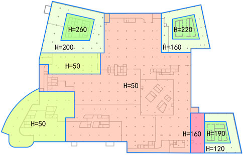
FIGURE 2. Foundation slab thickness (cm).
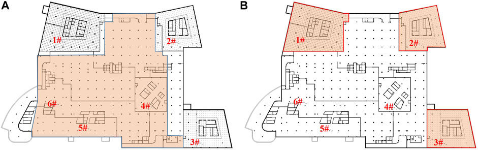
FIGURE 3. (A) Layout of uplift pile (B) Layout of CFG.
To acquire more accurate simulation of the actual engineering conditions of the project, the whole structure below ±0.000 was modeled completely in the study of the collaborative effect of the subgrade and foundation settlement. The wall, plate, column, beam, uplift pile and CFG pile in the underground structure are defined as elastic materials, where 3D solid element is adopted for the wall and plate, and 1D embedded beam unit for column, beam, uplift pile and CFG pile; the soil layer is defined as Mohr-Coulomb elastoplastic material, for which 3D solid element is adopted. The geometric model is divided into 3,836 meshes, and a total of 47,362 units and 285,770 nodes are set in the model. At the same time, the dead weight of the superstructure is equivalent to the load, and the modeling is completed after adding boundary conditions. The relevant models are shown in Figure 4.
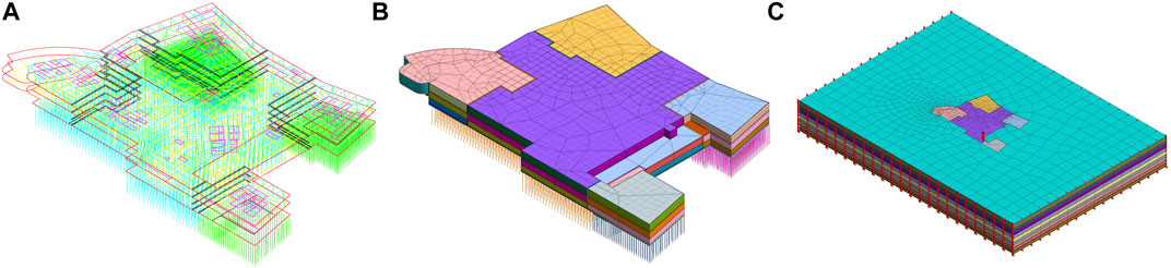
FIGURE 4. Finite element modeling: (A) Single line plan of underground structure; (B)Meshing of the underground structure; (C) Building an overall model.
The finite element model is calculated according to the preliminary foundation scheme, and the results are shown in Figure 5. The largest settlement is mainly concentrated in building 1# and 2#, while the smallest settlement is distributed in building 3# and 6#. The maximum settlement value appears at about 45.07 mm southeast corner of building 1#, and the minimum settlement value at about 13.80 mm southeast corner of building 3#. The settlement deformation of foundation is within 50 mm of the requirement of structural design, so the design scheme of foundation is feasible in settlement control. Considering the principle of structural optimization and making full use of the bearing capacity of subgrade, however, it is necessary to further optimize the scheme.
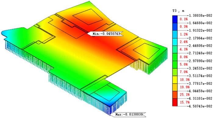
FIGURE 5. Contour diagram of overall settlement calculation in preliminary foundation scheme.
3.2 Optimization analysis of CFG pile composite foundation design
3.2.1 Standard calculation
Assuming that higher values of settlement happen due to lower stiffness of the CFG pile composite foundation, which is associated with lower amount of material used, the optimization objective is set to be the maximization of the settlement value, and this criterion will be used for the selection of the optimum combination of pile length, diameter and spacing. In this paper, settlement deformation under different pile spacing and pile length combinations is further analyzed according to the Code for Design of Building Foundation (2011). Herein described are the relevant calculation methods of CFG pile composite foundation:
(1) Calculation of composite foundation bearing capacity
According to the Technical Code for Composite Foundation (2012), the bearing capacity characteristic value of composite foundation with bond strength reinforcement should be calculated as follows:
Note:
The bearing capacity characteristic value of single reinforced pile can be estimated as follows:
Note:
(2) Calculation of foundation deformation
In the calculation of foundation deformation, the isotropic homogeneous linear deformation theory can be applied to the stress distribution in the subgrade, and the final deformation can be calculated as follows:
Note:
According to the self weight load of the upper structure, the structural calculation software PKPM is used to calculate the required value of bearing capacity (see the second column of Table 3). Based on the above calculation formula, it is required to control the pile length so that the pile end enters the sand layer with relatively high compression modulus, and to control the pile spacing within the range of 3–5 times of the pile diameter, taking the largest value as long as possible. On the premise of convenient construction, the pile diameter and pile length shall be unified as much as possible, and the pile length and pile spacing combinations of each CFG pile are screened as shown in Table 3. The name of each scheme is composed of two groups of figures connected with “-” in the middle. The first group of figures represents the group number, the second group of figures represents pile spacing.
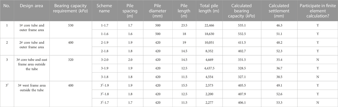
TABLE 3. Bearing capacity and settlement for various combinations of CFG pile lengths and spacing calculated by the standard method.
Because the collaborative settlement of the subgrade and foundation is considered in the finite element calculation, the settlement value calculated by finite element method may be smaller than that calculated by the codes. When the settlement of the same CFG scheme calculated by the codes is greater than the limit value of 50 mm, but the settlement calculated by the finite element less than 50 mm, the finite element calculation results can be considered. In this case, the total pile length can be smaller than the CFG pile scheme with the code calculation. In order to explore the optimization feasibility of CFG pile design scheme in settlement calculation on the premise that the bearing capacity just meets the requirements, in the design areas numbered 1, 2, and 3′ in Table 3, one design scheme with the settlement value less than 50 mm and one design scheme with the settlement value greater than 50 mm calculated by the codes is selected to participate in the finite element calculation. As the bearing capacity of No. 3 design area is very easy to meet the requirements, and the calculated settlement value is far less than 50 mm, the 3-1.9 scheme with the smallest total pile length can be directly selected for finite element calculation without optimization analysis.
3.2.2 Finite element analysis
To further study the applicability of each CFG pile scheme under the consideration of the interaction of superstructure, foundation and subgrade soil, the combined finite element calculation and analysis are carried out for several schemes whose settlement value calculated by the code method is about 50 mm as required by the design, and the feasibility of CFG pile composite foundation scheme optimization is discussed. Among them, it is easy to meet the design requirements for the core tube of building 3# and the east frame area outside the tube due to the low bearing capacity requirements, for the time being, the collaborative optimization is not discussed, and a fixed scheme is adopted to participate in the finite element calculation. The specific scheme combinations of finite element analysis are shown in Table 4.
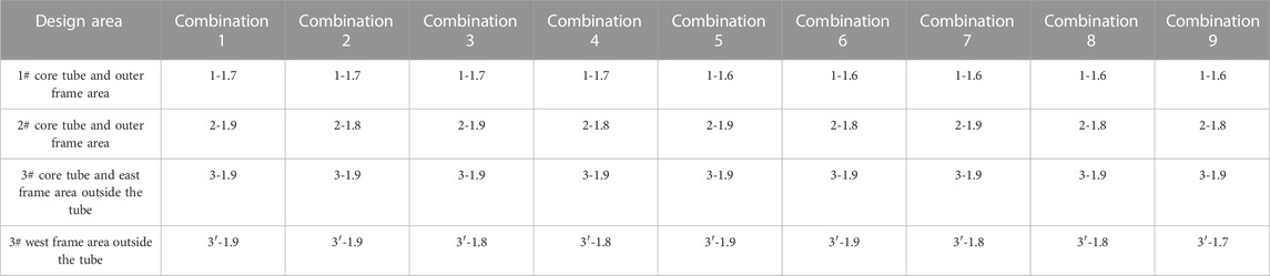
TABLE 4. Scheme combinations participating in finite element analysis.
The finite element calculation results of scheme combination 1–8 are shown in Figures 6(A–H):
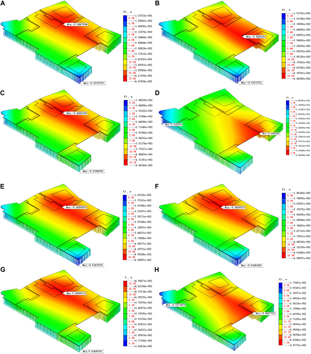
FIGURE 6. (Continued).
As can be seen from the above settlement calculation results, under the action of superstructure load, the settlement of CFG pile composite foundation in each area shows a different law from the strandard-based calculation:
(1) By comparing the maximum settlement of each area with the settlement calculated by the standard method, the later is generally larger;
(2) Only one settlement value can be provided for each area calculated by the code method, that is, each area has an equivalent settlement; the foundation settlement at any point of the raft can be read by finite element analysis. It mainly shows that the settlement of CFG pile composite foundation in each area is smaller at the edge of the raft, and greater at the center of the whole raft. This difference in the distribution of the settlement along the raft foundation is partially due to the difference in stiffness between the raft foundation and the underlying soil.
By comparing the scheme combinations, it can be seen that scheme combination 1 to scheme combination 8 can meet the design requirements of CFG pile composite foundation settlement of each region, i.e., being less than 50 mm. The total pile length of combined scheme 8 is the smallest among all schemes, and the calculated settlement value meets the requirements, so it can be considered that scheme combination 8 is the best. Under the design conditions of scheme combination 8, the settlement deformation of the building 1# area and building 2# area is very close to the limit value, while the settlement deformation of the frame area on the west side outside the building 3# tube still has some room for optimization. Therefore, on the basis of scheme combination 8, the design scheme of this area is adjusted to pile spacing of 1.7 m, which is calculated as scheme combination 9 to further optimize CFG pile design. Figure 7 below is the overall settlement calculation contour diagram of scheme combination 9. It can be seen from the settlement contour diagram that the settlement deformation of the area west of building 3# has exceeded the limit value of 50 mm, and scheme combination 9 cannot meet the design requirements, which is abandoned accordingly.
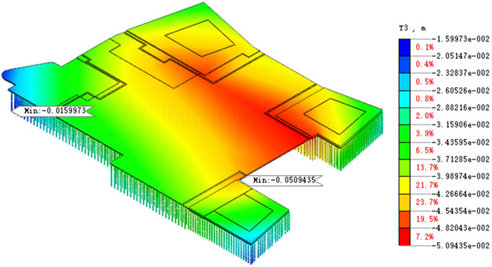
FIGURE 7. Scheme combination 9: overall settlement contour diagram.
The settlement value calculated according to the standard in scheme combination 8 is slightly higher than the design limit, while the finite element calculation with consideration of the overall coordination meets the design limit. According to the observation experience of building settlement in CFG pile composite foundation in Beijing area, the measured maximum value of building settlement is generally smaller than the calculated value of standard settlement, with a difference of about 9.2–28.7 mm. Based on the above analysis, the scheme combination 8 can be used as the composite foundation optimization design scheme to guide the construction of the project. In addition to meeting the design requirements, the CFG pile optimization scheme reduces the pile length by 5908 m compared with the preliminary scheme, saving about 15% of the direct cost and creating good economic benefits.
4 Optimization analysis of pouring time of late poured band
In the construction process of the main building and skirt building or pure basement, the load of the main building is large, thus the settlement is large, while that of skirt building or pure basement is small, thus the settlement is small. When the late poured band is filled too early, the settlement difference between the two sides is large, leading to cracking of the foundation raft, and even yielding of the configured reinforcement, and consequently to bending failure of the raft. Too much late to fill the late poured bands may lead to greater safety risk of the project and increase the investment. In this paper, the general idea of pouring time optimization for late poured bands is determined as follows:
(1) Obtain the settlement and deformation of building blocks on both sides of each late poured band respectively through finite element calculation and analysis of raft foundation settlement;
(2) Analyze the stress model of raft foundation, and use the structural design method to calculate the maximum settlement difference that the stiffness of late poured band can bear after pouring, compare the differential settlement limits in the codes, and take the small value of both as the maximum settlement difference;
(3) Compare the maximum settlement difference with the calculated settlement values of the two sides of the late poured band obtained by finite element analysis method, and finally determine the pouring time node of the late poured band;
(4) Calculate and verify the feasibility of the pouring time.
Considering load difference and raft size, four late poured bands are set on the bottom plate in foundation design, which are located in the surrounding area of building 1#, 2#, 3#, and 6# respectively to adjust settlement difference, as shown in Figure 8.
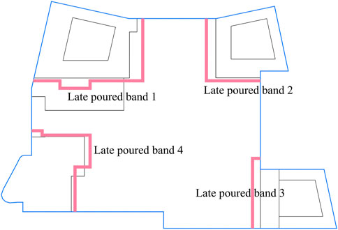
FIGURE 8. Schematic diagram of late poured bands position.
4.1 Differential settlement calculation on both sides of late poured band
According to the construction organization arrangement of each floor of each building provided by the project owner, combined with the equivalent load of each floor given by the structural designer, a 43-stage construction scheme is established, which is consistent with the actual working conditions, and the final overall settlement and deformation contour diagram is calculated by simulation, as shown in Figure 9.
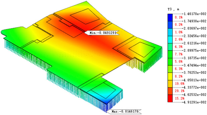
FIGURE 9. The overall settlement contour diagram in the complete construction stage of scheme combination 8.
In the subsequent analysis, the differential settlement values on both sides of the late poured band are determined under the most unfavorable combination scenario, that is, the maximum settlement value is taken for the building side with a larger load, and the minimum settlement value for the building side or basement side with a smaller load. Subject to the preset construction sequence for each floor of the project, the calculated settlement deformation values are shown in Figure 10.
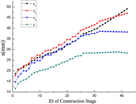
FIGURE 10. Settlement deformation at each construction stage.
In the figure, s1 is the maximum settlement value of building 1#, s2 the maximum settlement value of building 2#, s3 the maximum settlement value of building 3#, and s the minimum settlement value of basement area.
Settlement differences of each late poured band under the most unfavorable combination scenario are shown in Figure 11. Among them, the late poured band four is not analyzed this time because of the low structural height of the building 6# and the small load of the basement on the other side. Therefore, the analysis is not made this time, and the late poured band four can be sealed according to the conventional practice, that is, after the structure of the building 6# is topped out. According to the calculation results, the maximum value of differential settlement on both sides of late poured band 1, late poured band 2 and late poured band 3 are 20.85 mm, 18.74 mm and 10.08 mm, respectively.
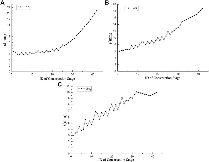
FIGURE 11. Differential settlement of the two sides of the late poured band. (A) Late poured band 1 (B) Late poured band 2. (C) Late poured band 3.
4.2 Optimization analysis of pouring time of late poured band
During the foundation design, raft with different thickness shall be set according to the upper load and the lower subgrade type to meet the requirements in respect to bearing capacity and deformation. According to the Code for Design of Building Foundation (2011) and the calculation results with the structural calculation software PKPM, the range of settlement difference that raft stiffness can resist in late poured band area is as follows:
(1)For building 1# area, i.e., late poured band 1, ≤20 mm;
(2)For building 2# area, i.e., late poured band 2, ≤15 mm;
(3)For building 3# area, i.e., late poured band 3, ≤10 mm;
According to the empirical provisions in the Code for Design of Building Foundation (2011), the differential settlement between the main building and the adjacent skirt building is less than 0.1% of its span, which can ensure the safety of the foundation structure. In engineering practice, subject to the unfavorable combination, the minimum value of the differential settlement limit of raft stiffness resistance and the differential settlement limit of span suggested by the code, that is, the differential settlement limit
We take the difference between the maximum value
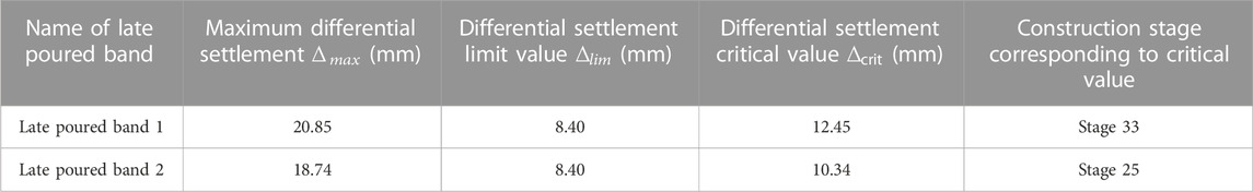
TABLE 5. Critical value of differential settlement for late poured band which is poured in advance.
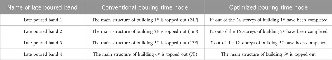
TABLE 6. Time nodes of pouring work of late poured band.
After determining the advance pouring time of the late poured band, the influence of its advance pouring on the overall settlement is subject to further discussion and exploration to verify its applicability. According to the optimal pouring time node of the late poured band described in Table 6, under the corresponding construction stage of Midas GTS NX finite element model, all the late poured band models are activated, so that all the late poured bands can be added to the calculation. Figure 12 shows the settlement contour diagram of the late poured band filled at the optimum time node according to Table 6. It can be seen that the early pouring of the late poured band slightly reduces the overall settlement of the foundation, which is beneficial to the overall settlement control. The pouring time of the late poured band can be optimized according to Table 6.

FIGURE 12. Contour diagram of settlement of late poured band.
5 Conclusion
In this paper, taking a large commercial complex as an example, Midas GTS NX finite element software is used to verify and optimize the foundation scheme, and combined with the hierarchical loading conditions in various regions, the time nodes of the late poured band filled in advance and the impact on the cooperative settlement of the foundation are studied. This method can be used to verify and optimize the design scheme of composite foundation and the pouring time of late poured band. The following conclusions can be drawn from the current study:
(1) The finite element analysis can realize the stress redistribution calculation of the foundation slab under the differential load of the superstructure, which makes the load distribution in each area more in line with the reality, and the calculated value of settlement by finite element analysis is generally smaller than that obtained in the standard calculation;
(2) The settlement calculation results of finite element analysis show that the settlement at the edge of the raft is small, and the settlement at the center of the raft and the places with large load (building 1#, building 2# and their adjoining areas) is large; the secondary stress of raft can be effectively reduced by reasonably setting the late poured band between building 1# and building 2#, at the junction between the main building and the skirt building and other places where the settlement is large, to adjust the settlement.
(3) The finite element calculation verifies that the preliminary foundation scheme of the project designed according to the standard method is feasible under the settlement control considering the upper load, foundation strength and geological conditions;
(4) Considering the interaction of the whole raft and different subgrade types under the raft, the composite foundation scheme can be further optimized to ensure the structural safety and save the project cost.
(5) Through finite element analysis of the settlement difference between the two sides of the late poured band, with due consideration of the maximum differential deformation that the raft can bear in the structural design and the requirements of relevant codes, the advance pouring time of the late poured band can be determined, and both the construction speed and quality can be improved.
Due to various conditions of the construction site, this paper only adopts the finite element analysis method combined with the actual situation of the project. Later, the project test research will be carried out in combination with the project conditions to enrich the research results.
Data availability statement
The raw data supporting the conclusion of this article will be made available by the authors, without undue reservation.
Author contributions
LX, BT, and SL contributed to conception and design of the study. YG and XC organized the database. LX performed the statistical analysis. SL wrote the first draft of the manuscript. All authors contributed to manuscript revision, read, and approved the submitted version.
Funding
This work was supported by the Guangxi Natural Science Foundation (2020GXNSFAA297199), the National Natural Science Foundation of China (41867035), and the project of Guangxi Key Laboratory of Geotechnical Mechanics and Engineering (2016-A-01). The authors gratefully acknowledge the financial support.
Conflict of interest
Authors LX and SL were employed by WSGRI Engineering & Surveying Incorporation Limited.
The remaining authors declare that the research was conducted in the absence of any commercial or financial relationships that could be construed as a potential conflict of interest.
Publisher’s note
All claims expressed in this article are solely those of the authors and do not necessarily represent those of their affiliated organizations, or those of the publisher, the editors and the reviewers. Any product that may be evaluated in this article, or claim that may be made by its manufacturer, is not guaranteed or endorsed by the publisher.
References
Basuony, E. G., Ahmed, A. G., Youssef, A. F., and Raia, M. A. (2013). Behavior of raft on settlement reducing piles: Experimental model study. J. Rock Mech. Geotechnical Eng. 5 (05), 389–399. doi:10.1016/j.jrmge.2013.07.005
Code for Design of Building Foundation (2011). Ministry of housing and urban rural development of the people's Republic of China, GB 50007-2011. Beijing, China: China Building Industry Press.
Deb, P., and Pal, S. K. (2022). Structural and geotechnical aspects of piled raft foundation through numerical analysis. Mar. Georesources Geotechnol. 40 (7), 823–846. doi:10.1080/1064119X.2021.1943083
Halder, P., and Manna, B. (2022). Performance evaluation of piled rafts in sand based on load-sharing mechanism using finite element model. Int. J. Geotechnical Eng. 16 (5), 574–591. doi:10.1080/19386362.2020.1729297
Jia, Y., Lu, L., Wu, G., Liu, Y., and Mo, X. (2022). Spatial nonlinear simulation analysis on the temperature shrinkage effect of a super-long frame structure considering the construction process. Processes 10, 1874. doi:10.3390/pr10091874
Jiang, M., Deng, K., Xu, P., Wang, X., and Qiang, S. (2019). Study on the reasonable spacing of post-pouring zone for 50m long inverted-T type concrete structure on soft foundation. IOP Conf. Ser. Earth Environ. Sci. 304, 052007. doi:10.1088/1755-1315/304/5/052007
Li, G. (2019). Deep investigation on post-cast strip setting[J]. Build. Struct. 49 (3), 3837–3845. doi:10.19701/j.jzjg.2019.03.007
Roberts, L. A., and Misra, A. (2009). Reliability-based design of deep foundations based on differential settlement criterion. Can. Geotechnical J. 46 (2), 168–176. doi:10.1139/T08-117
Taghavi Ghalesari, A., and Janalizadeh Choobbasti, A. (2016). Numerical analysis of settlement and bearing behaviour of piled raft in Babol clay. Eur. J. Environ. Civ. Eng. 22, 978–1003. doi:10.1080/19648189.2016.1229230
Technical Code for Composite Foundation (2012). Ministry of housing and urban rural development of the people's Republic of China, JGJ79-2012. Beijing, China: China Building Industry Press.
Wang, C., Cao, J., and Zhao, L. (2012). A settlement compensation method for design of settlement controlled piled raft foundations under vertical loadings. Appl. Mech. Mater. 1975 (412), 857–864. doi:10.4028/www.scientific.net/AMM.204-208.857
Wang, L., Zhao, X., and Liu, S. (2021). A study of differential foundation settlement of piled raft and its effect on the long-term vertical shortening of super-tall buildings. Struct. Des. Tall Special Build. 30, e1832. doi:10.1002/tal.1832
Wang, S., Di, D., and Zhou, S. (2014). Settlement and contact pressure characteristics of the main building and annex with post-cast strips on medium or low compressible soil[J]. Rock Soil Mech. 35 (S2), 313–318. doi:10.16285/j.rsm.2014.s2.086
Ye, J., and Chi, L. (2011). The determination of settlement post-cast band closure time based on ANSYS analysis[J]. Build. Sci. 27 (9), 20–23. doi:10.13614/j.cnki.11-1962/tu.2011.09.020
Yuanming, D., and Qinnan, S. (2017). Study on mechanical property and closing time of post-casting belt of main building and podium building under mutual action[J]. Archit. Technol. 48 (02), 211–214. doi:10.13731/j.issn.1000-4726.2017.02.029
Zhang, Z., Zhang, R., Huang, M., and Gong, J-F. (2019). Optimization analysis of pile group foundation based on differential settlement control and axial stiffness under vertical loads[J]. Rock Soil Mech. 40 (6), 2354–2368. doi:10.16285/j.rsm.2018.1409
Zhao, W., Zhen, M., and Minzhang, Y. (2012). Research on analysis and design method of the pile-raft foundation with post-cast concrete strip. Adv. Mater. Res. 446-449, 1541–1545. doi:10.4028/www.scientific.net/AMR.446-449.1541
Keywords: composite foundation, foundation settlement, late poured band, collaborative analysis, design optimization
Citation: Xie L, Tang B, Liu S, Gong Y and Cheng X (2023) Study on optimization of pouring time for late poured band. Front. Built Environ. 8:1059920. doi: 10.3389/fbuil.2022.1059920
Received: 02 October 2022; Accepted: 16 December 2022;
Published: 04 January 2023.
Edited by:
Vasant Annasaheb Matsagar, Indian Institute of Technology Delhi, IndiaReviewed by:
Tadesse Gemeda Wakjira, University of British Columbia, Okanagan Campus, CanadaGeorge Papazafeiropoulos, National Technical University of Athens, Greece
Copyright © 2023 Xie, Tang, Liu, Gong and Cheng. This is an open-access article distributed under the terms of the Creative Commons Attribution License (CC BY). The use, distribution or reproduction in other forums is permitted, provided the original author(s) and the copyright owner(s) are credited and that the original publication in this journal is cited, in accordance with accepted academic practice. No use, distribution or reproduction is permitted which does not comply with these terms.
*Correspondence: Bin Tang, dGFuZ2JpbkBnbHV0LmVkdS5jbg==