 Michele Egidio Bressanelli
 Marco Bosio1
 Andrea Belleri
 Paolo Riva
94% of researchers rate our articles as excellent or good
Learn more about the work of our research integrity team to safeguard the quality of each article we publish.
Find out more
ORIGINAL RESEARCH article
Front. Built Environ., 18 March 2021
Sec. Earthquake Engineering
Volume 7 - 2021 | https://doi.org/10.3389/fbuil.2021.645497
This article is part of the Research TopicAdvances in Seismic Performance and Risk Estimation of Precast Concrete BuildingsView all 11 articles
The 2012 Emilia earthquakes caused significant damage to existing precast reinforced concrete (RC) industrial buildings not specifically designed to resist seismic actions. The main failure mechanisms were related to the loss of support of beams and roof elements caused by high relative displacements, to the failure of the mechanical connections and consequent fall of cladding panels, to the damage at the base of the columns and to the collapse of RC forks at the top of the columns. In all cases, the behavior of the connections, and specifically of beam-to-column connections, demonstrated to be crucial, given that they may inhibit the exploitation of strength and ductility reserves in precast elements. This paper presents a beam-to-column connection restraint-device for precast industrial buildings. The device can be applied to existing structures to transfer horizontal seismic forces between beams and columns and to increase the energy dissipation of the system. Design criteria were defined with the aim to limit the relative maximum displacement at the beam-to-column interface and to mitigate the out-of-plane overturning of the beam. Numerical analyses were carried out to define a suitable shape of the device and to investigate its effectiveness in terms of both local and global behavior. To validate the computational results, experimental tests have been also carried out. The tests allowed to classify the device as “dissipative” according to UNI EN 15129. Finally, the design procedure has been validated considering a one-story industrial building case study designed in accordance with the Italian building code.
Precast concrete structures are widely used for industrial buildings in Italy, as they can cover large surfaces, ensure high quality controls of materials and elements and allow for shorter construction times when compared to conventional reinforced concrete (RC) buildings. For example, there is a significant reduction in construction time associated with concrete curing and a consistent reduction in costs due to the use of precast elements, which are easily transportable and erected on site at low expenses and great speed; these characteristics are essential when dealing with industrial facilities, where buildings develop on large surfaces and construction time is directly related to the time to business for the facility. The typical structural layout develops mainly on a single level and it is characterized by simple and regular layouts, with cantilever columns pin-connected to pre-stressed beams which support the roof elements. Generally, the columns are either placed inside pocket footings or connected to the foundation by means of mechanical devices or grouted sleeves (Belleri and Riva, 2012; Dal Lago et al., 2016).
Before the enforcement of modern anti-seismic regulations in Italy, the buildings not specifically designed for seismic actions were characterized by beams simply supported on the columns; the contact surface was typically equipped with a neoprene pad to spread the load over the support, and the horizontal load transfer between the beam and column was provided solely by friction. Such beam-to-column friction connections, basically designed to support only gravitational loads, do not contribute to the seismic resistance of the building. Indeed, as stated by current regulations, beam-to-column connections cannot rely on friction in seismic regions; for such reason dowel connections are usually adopted.
The seismic sequence that affected the territory of Emilia-Romagna, Veneto and Lombardia regions in May 2012 had a strong impact on areas characterized by a medium-low seismic hazard, i.e., acceleration on rigid soil in the order of 0.10 ÷ 0.15 g considering a return period Tr equal to 475 years. An updated classification of the seismic hazard was only stated in 2003 (OPCM 3274, 2003). Before that, numerous buildings were designed and built without modern anti-seismic criteria. Such buildings have highlighted considerable vulnerability to recent seismic events (Bournas et al., 2014; Magliulo et al., 2014; Belleri et al., 2015a; Belleri et al., 2015b; Ercolino et al., 2016; Minghini et al., 2016; Belleri, 2017; Nastri et al., 2017; Palanci et al., 2017). These vulnerabilities are related to multiple local collapse mechanisms and vulnerabilities such as the loss of support of the roof elements and/or beams, the overturning of the RC cladding panels and the collapse of RC columns or forks at the top of the columns (Brunesi et al., 2015; Belleri et al., 2016; Belleri et al., 2017a; Dal Lago et al., 2018; Ercolino et al., 2018; Torquati et al., 2018; Iervolino et al., 2019; Bosio et al., 2020).
The vulnerability related to the loss of support in the beam-to-column connection (Casotto et al., 2015; Demartino et al., 2018) is due to the lack, or inefficiency, of an adequate mechanical connection able to transfer the seismic actions from the beams to the top of the columns. To counteract this vulnerability and improve the seismic response of precast structures designed for gravity loads, a possible dissipative beam-to-column connection device has been investigated herein. The optimal device shall be able to improve the seismic performance of precast structures by increasing the degree of fixity of the connection and the energy dissipation while, at the same time, limiting the interference with the existing non-structural elements and systems (Belleri et al., 2017b; Magliulo et al., 2017). The device has been defined on the basis of the following criteria: kinematic compatibility with the existing structure, energy dissipation, ease of mounting and replacement after a seismic event and limited interference with the existing industrial systems (as for instance electrical and plumbing). For the last reason, a crescent-moon-shaped device has been selected (Palermo et al., 2015; Hsu and Halim, 2017). It is interesting to note that other types of devices have been recently applied at the beam-to-column joints, such as the friction devices reported in the FREEDAM project (Santos et al., 2019; Francavilla et al., 2020) and the carbon-wrapped steel tubes reported in Pollini et al. (2020).
The design, modeling and analysis procedures used for the definition of the selected device are described considering its application to single-storey precast RC frames. Two configurations have been defined: the first one considers the dissipative device applied directly to the structure while the second one is characterized by placing the dissipative device into an elastic frame to improve the energy dissipation by acting as a lever mechanism. Both solutions allow to increase the frame lateral stiffness and the energy dissipation capacity. The structural performance and the stability of the device have been preliminary evaluated by means of buckling and non-linear cyclic analyses. Then an experimental campaign was carried out. On the basis of the experimental results, it has been possible to classify the device as “dissipative,” according to EN 15129 (2018). Finally, a design procedure was defined and validated through non-linear response history analyses on a case study.
The dissipative device provides an additional source of energy dissipation for the structure and promotes a stiffness increase at the beam-to-column connection. The selected device consists of a steel element with a “crescent-moon” shape that allows to dissipate energy by deforming and plasticizing homogeneously along its surface. The device has been selected and defined for applications in beam-to-column connections with fork or corbels at the top of the columns, which are the main types of existing old beam-to-column connections present in typical precast industrial buildings.
The design of the dissipative device was performed by analyzing the output of various geometry configurations under monotonic and cyclic loading. The geometry of the element was initially calibrated to develop a uniform plasticization (Figure 1).
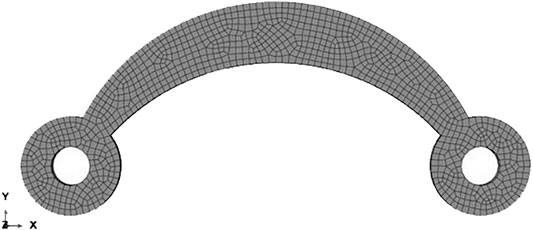
FIGURE 1. Finite element scheme of the dissipative device.
The finite element analyses were carried out considering both geometric and material nonlinearities. Three different device curvatures of the crescent-moon element have been analyzed to define the optimal shape to avoid instability, to maximize the energy dissipation and to ensure a symmetrical cyclic behavior in tension and compression. Starting from the device in its basic configuration (Figure 1), the rise has been increased (prefix ‘A’) or reduced (prefix ‘B’) by 50%. Each solution was analyzed considering a thickness of 5 and 10 mm to investigate its influence on the deformative behavior of the element. Figure 2A shows the six configurations analyzed.
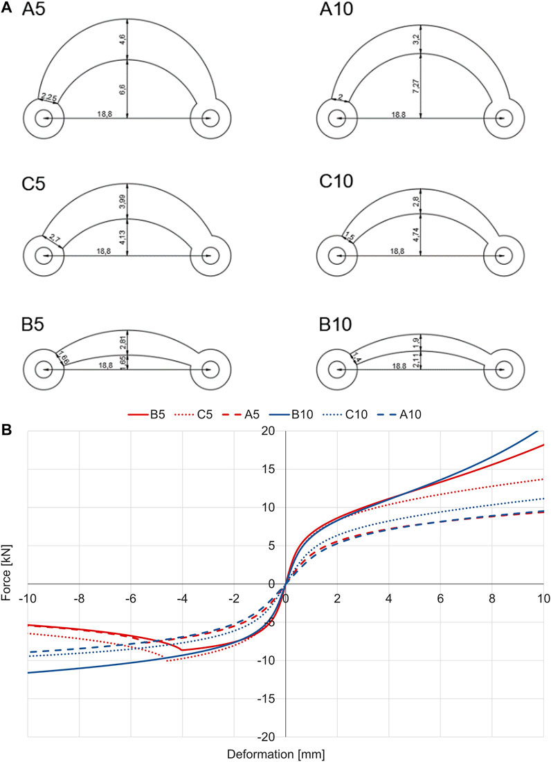
FIGURE 2. Selected geometries of the device as a function of the curvature and the thickness (measures expressed in centimetres) (A) and results of the associated non-linear static analyses (B). Note: considering the device id, the letter A, B or C indicates the curvature of the device while the following number indicates the thickness expressed in millimetres.
Monotonic analyses in compression and tension were conducted. Initially, each of the six configurations was modeled in order to carry out a stability check; subsequently, a non-linear analysis with displacement control was carried out (Figure 2B). The selected material non-linearity was in accordance with the Ramberg-Osgood’s constitutive law Eq. 1.
Where ε and σ represent the logarithmic deformation and Cauchy stress tensor, respectively, E represents the Young’s modulus, σ0 represents the stress at the yield point, α is a coefficient indicating the increase in yield strength and n is the exponent indicating the level of plasticization. In these analyses, a Young’s modulus equal to 210 GPa, a Poisson’s ratio equal to 0.3, a yield strength equal to 240°MPa, an exponent n equal to 5 and α equal to 1 were used. The geometric non-linearity was considered by introducing an out-of-plane imperfection according to the first buckling mode. The influence of the temperature was not considered.
The devices with thickness equal to 5 mm showed buckling for displacements close to 5 mm, i.e., deformations of the order of 3%. The devices with a thickness greater than 10 mm were not affected by this issue. When subjected to tension load, the B5 and B10 devices showed a significant increase in capacity due to the rope effect as the devices straightened. In fact, once the maximum deformation for which the device becomes almost rectilinear has been reached, there is a sharp increase in stiffness and load until the rupture of the element, which develops by necking at the smaller cross-section. This effect is less noticeable for devices C10 and A10, which are characterized by a higher rise.
The buckling of the devices has been also assessed through the closed form formulation for curved rods Eq. 2, where Mcr represents the elastic critical moment for buckling (Timoshenko and Gere, 2009):
IX represents the moment of inertia in the orthogonal plane defined as 1/12Hmeanb3, E represents the elastic modulus, R represents the mean radius of curvature of the device, b is the thickness of the device, α1 is the opening angle, Hmean is the mean cross-section height and C is defined by the product between the shear module G and the torsional stiffness JT. Considering that the elastic critical bending moment Mcr is equal to the product between the critical load Pcr and the lever arm h, we obtain that:
Table 1 reports the critical moment and load associated with each configuration. The results confirm what obtained from the finite element analyses (Figure 2B).
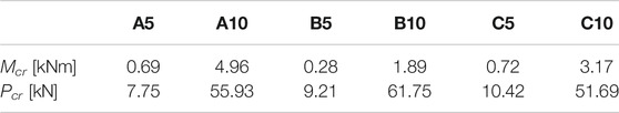
TABLE 1. Calculation of buckling with Eq. 2 for each configuration of devices.
After analyzing the influence of the rise and the thickness of the device, additional cyclic analyses were carried out to evaluate the symmetry of the device in tension and compression loading. In this case the cyclic analyses were carried out considering an elasto-plastic behavior of the material based on the values obtained from tensile tests conducted on dog-bone specimens. Experimental tests were carried out to validate the results. Full-scale specimens were produced for the six main configurations analyzed: A5, B5, C5, A10, B10 and C10. The tests were conducted in displacement control. Figure 3 and Figure 4 compare the results of the FEM analyses with the results obtained from the experimental tests for each of the aforementioned configurations during monotonic and cyclic loading, respectively.
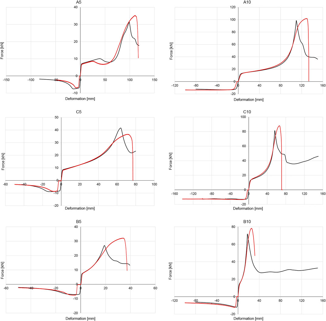
FIGURE 3. Comparison between monotonic numerical results (black line) and experimental tests (red line).
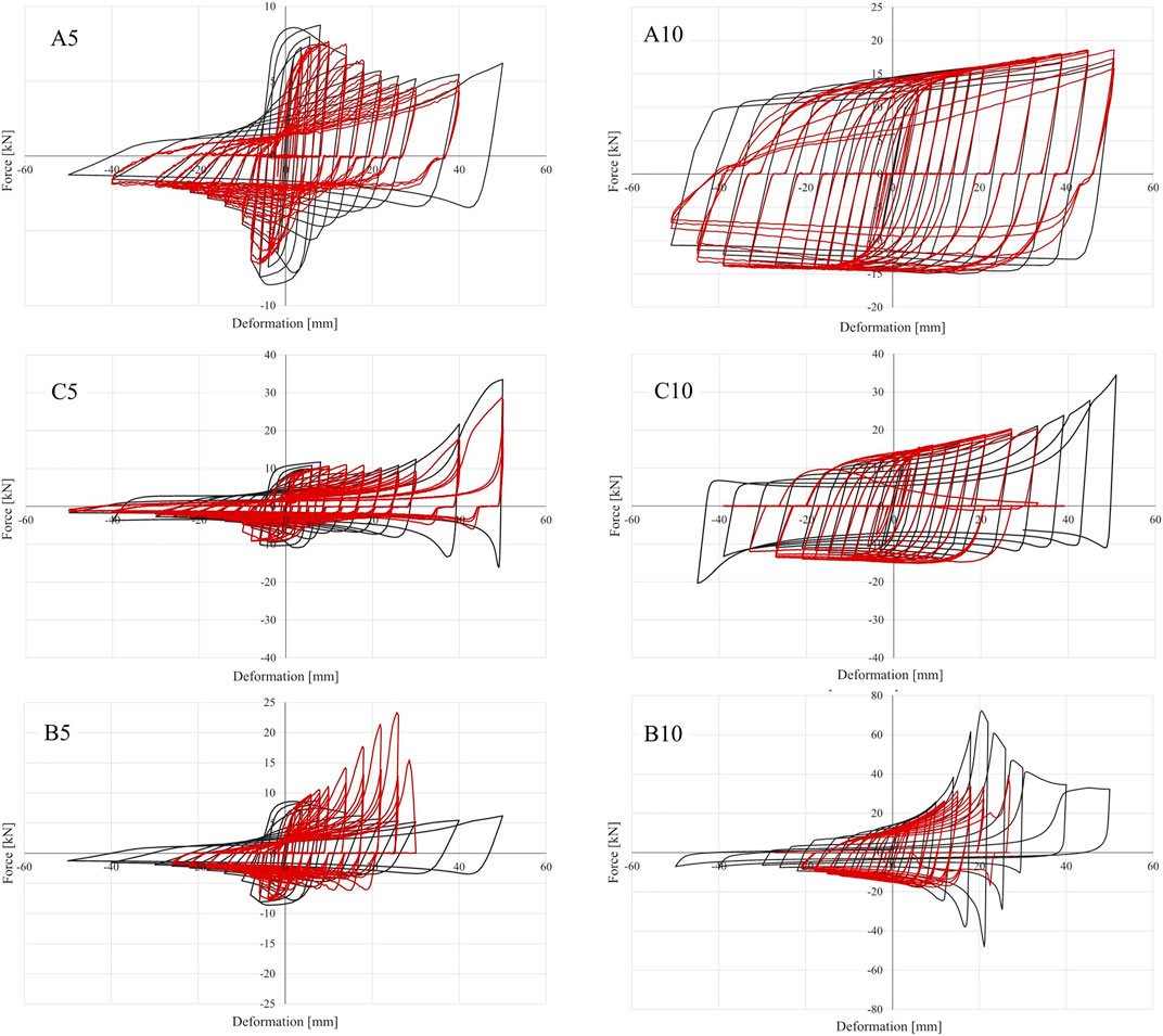
FIGURE 4. Comparison between cyclic numerical results (black line) and experimental tests (red line).
The monotonic results in Figure 3 show a fair resemblance between the values expected from finite element simulations and those obtained from experimental tests. The main differences were found for the tension phase, where the maximum force is reached for displacements lower than those observed in the experimental tests. The small differences in the origin are due to sliding caused by bolt-hole gap. The devices with higher rise and with thickness equal to 1 cm are characterized by almost symmetrical hysterical cycles (specifically C10 and A10). Except for the device C5, the devices showed higher maximum force values during the experimental test than those obtained from numerical simulations.
The cyclic results in Figure 4 show a good agreement between the experimental tests and the finite element simulations, especially for the device A10. Significant differences are evident in devices with lower rise, namely B5 and B10, where the finite element analyses are not able to correctly predict the experimental cyclical results. The cyclic tests on devices with a thickness equal to 5 mm confirmed the buckling issues previously encountered with monotonic analyses.
On the basis of the analyses carried out, an optimal geometry for the dissipative device was defined.The rise was increased to obtain a symmetrical hysteresis and avoid the presence of softening during compression. The thickness was increased to 20 mm to inhibit buckling and to dissipate energy in a stable manner. The height of the mid cross-section was increased to reduce the dissipation in this region and to increase the global stability of the device. The final device, referred to as M1 device, (Figure 5A) has a span equal to 720 mm and it is made by a steel element pin-connected to end steel plates connected to the column and beam through post installed anchors (as in Figures 5C,D). The connecting plates have been designed to remain elastic after the yielding of the device (Figures 5E,F). The slots in the plates allow for tolerance of anchor bolts due to the possible interference with longitudinal rebars and stirrups in the connected elements. The anchor bolts could be pretensioned to limit or avoid the plate detachment. The crescent-moon element allows to dissipate energy and to limit the sliding between the beam and the column in the case of friction connections.
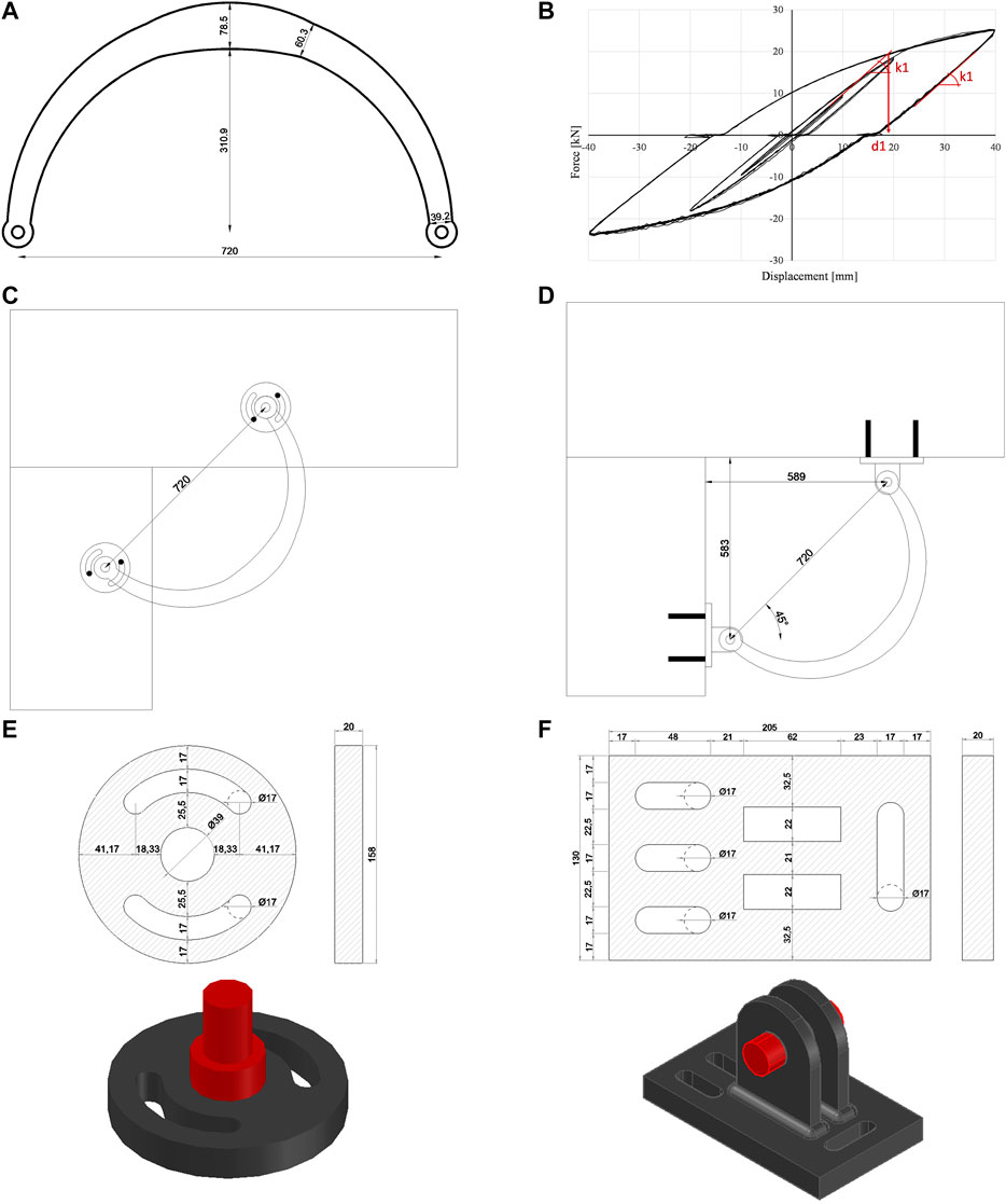
FIGURE 5. Geometry of the beam-to-column device (A); experimental force-displacement behavior (B); application of the device on beam and column from the side (C) and from below (D); geometry of the end-plates (E, F).
As it can be seen from Figure 5B, the device is able to offer a symmetrical behavior in tension and compression, a good energy dissipation and it is not subjected to relevant capacity decay following repeated cyclic tests.
In order to increase the stiffness and dissipation capacity offered by the investigated device, the crescent-moon element can be assembled in an amplification frame able to increase the effects of the relative displacements between the beam and the column. An example of such an assembly is shown in Figure 6A. This configuration consists of two steel elements characterized by equal length and three devices: two long span devices (530 mm) and one additional device with a lower span (212 mm). The shape and size of the devices was selected to achieve stable global behavior in tension and compression. This system ensures a stable energy dissipation, an almost symmetrical behavior and a low interference with fixtures. A cyclic nonlinear static analysis was carried out and the results are shown in Figure 6B (black line) along with the comparison of a single M1 device (green line).
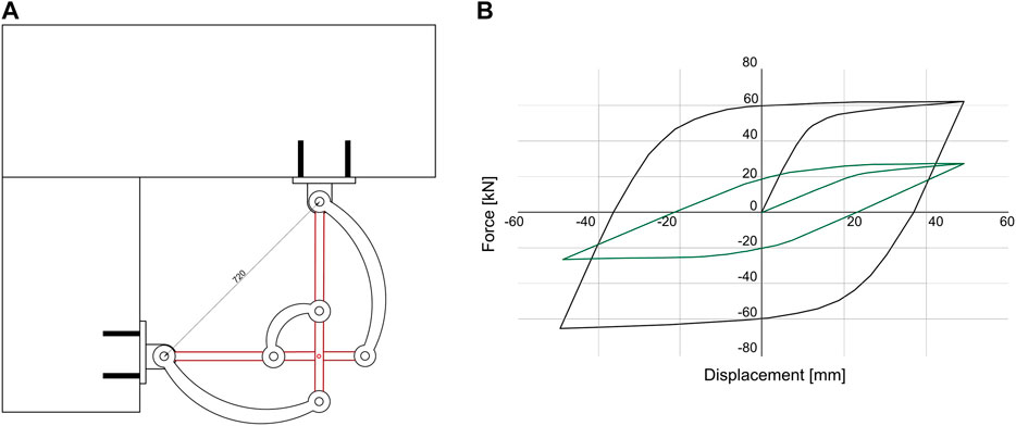
FIGURE 6. Configuration for the displacement amplification system (A) and hysteresis comparison between such system and a single M1 device (B).
Various tests on the investigated device were conducted in accordance with the European Standard EN 15129 “anti-seismic devices” under displacement control. EN 15129 (2018) .covers the design of devices that are provided in structures, with the aim of modifying their response to the seismic action. It specifies functional requirements and general design rules of the devices for the seismic design situations, material characteristics, manufacturing and testing requirements, as well as assessment and verification of constancy of performance, installation and maintenance requirements. The procedure used in the cyclic tests was defined according to paragraph six of EN 15129 (2018). The device could be classified as a non-linear displacement dependent device characterized by a non-linear force-displacement response, with a stable behavior for the required number of cycles and substantially independent of speed. For these devices, the standard requires the following tests:
1. Monotonic failure tests at low speed to determine the failure displacement. The collapse shall not occur before reaching a displacement value equal to the design displacement (dbd) multiplied by two coefficients ɣb and ɣx and for a load equal to the design load (VEbd) multiplied by the same coefficients;
2. Cyclic tests with repeated cycles of increasing amplitude: 5 cycles at 0.25°dbd, 5 cycles at 0.5°dbd and 10 cycles at dbd. The number of cycles was taken as the minimum indicated in EN15129.
For each cyclically tested sample, an overload test was also carried out to assess the stability of the device and the absence of decreasing trends in the load-displacement curve. The parameters necessary to define the behavior of the device are: the maximum load reached Fmax, the displacement at the maximum load dlim, the design displacement dbd, the design load VEbd (i.e., the load associated with the design displacement), the stiffness of the first elastic branch k1, the stiffness of the second plastic branch k2, the effective stiffness keffb (defined as the ratio of VEbd design load to dbd design displacement) and the effective damping ξeffb (corresponding to the energy dissipated during the cycles at the design displacement dbd). Figure 7 shows these parameters.
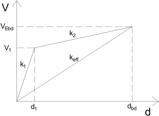
FIGURE 7. Main parameters describing the hysteretic behavior of the system.
The maximum design displacement is equal to 121 mm and it was obtained by dividing the displacement at the reference limit dlim by the two coefficients (ɣb = 1.1 and ɣx = 1.5). The choice of a design displacement of 40 mm is therefore compatible with the experimental results. The devices tested have successfully passed the required displacement history without failure. According to EN 15129 (2018), the tested devices have a stable behavior with the following design parameters: design displacement dbd equal to 40 mm; displacement at yield d1 equal to 18.6 mm; first branch stiffness k1 equal to 1.003 kN/mm; second branch stiffness k2 equal to 0.268 kN/mm; design effective stiffness keff equal to 0.595 kN/mm; design effective damping ξeff equal to 18.91%; design axial load VEbd at dbd equal to 23.9 kN.
For the definition of the parameter d1, i.e., the displacement at yielding, a bi-linearization of the curve has been carried out. Specifically, a straight line was drawn from the origin with inclination equal to k1; the yield strength was taken as the point corresponding to the intersection of such line with the load-displacement curve of the device, Figure 5B. According with EN 15129 (2018), the device can be classified as a non-linear dissipative device.
The considered device can be implemented in the seismic retrofit of existing precast concrete buildings, where it may be placed at the beam-to-column joint (Figures 5C,D) to avoid sliding at the connection and to provide energy dissipation. The device may be also used in new buildings.
According to Eurocode 8 part 3 (CEN, 2005), the retrofit design procedure shall include the following steps: conceptual design, analysis and verification. The conceptual design shall cover the following: selection of techniques and/or materials, as well as of the type and configuration of the intervention, preliminary estimation of dimensions of additional structural parts and preliminary estimation of the modified stiffness of the retrofitted elements.
The design procedure considers the equivalence between the frame with the beam-to-column devices in their actual position (Figures 8A,B) and an idealized frame with a lumped rotational spring at each joint (Figure 8C).
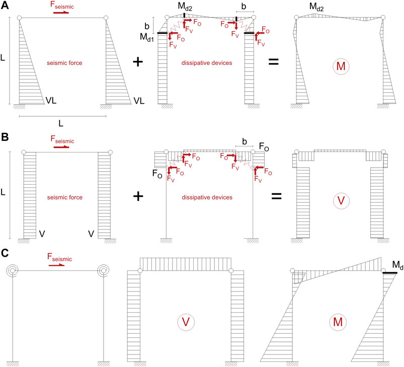
FIGURE 8. Contribution to the bending moment (A) and shear (B) diagram of the device in its actual position and in the case of idealized frame with lumped rotational springs at the joints (C).
In Figures 8A,B, Fo and Fv are the vertical and horizontal forces of the device, Md is the moment due to the device and b is the distance between the points of application of the device and the beam-to-column connection, which, in the preliminary design phase, is assumed as a hinge. On the basis of this scheme, it is possible to assess the shear and bending moment in the beam and in the columns before and after placing the device. The following equations may be derived for the bending moment in correspondence to the device on the column and on the beam, respectively:
Where L is the length of the beam, FO and FV are the horizontal and vertical components associated with the device, respectively. On the basis of the bending moment diagrams and assuming that the dimension b of the device is small in relation to the length of the beam and the height of the column, we obtain that:
Therefore, it is possible to replace the actual static scheme with the simplified scheme of Figure 8B: the higher the L/b ratio, the better the approximation.
The design procedure consists in defining the required number of devices in each connection. Figure 9 shows the flow chart of the design procedure. For the design, it is assumed that the crescent-moon device is the only element able to transfer horizontal actions from the beam to the supporting columns, i.e. the contribution of friction is neglected.
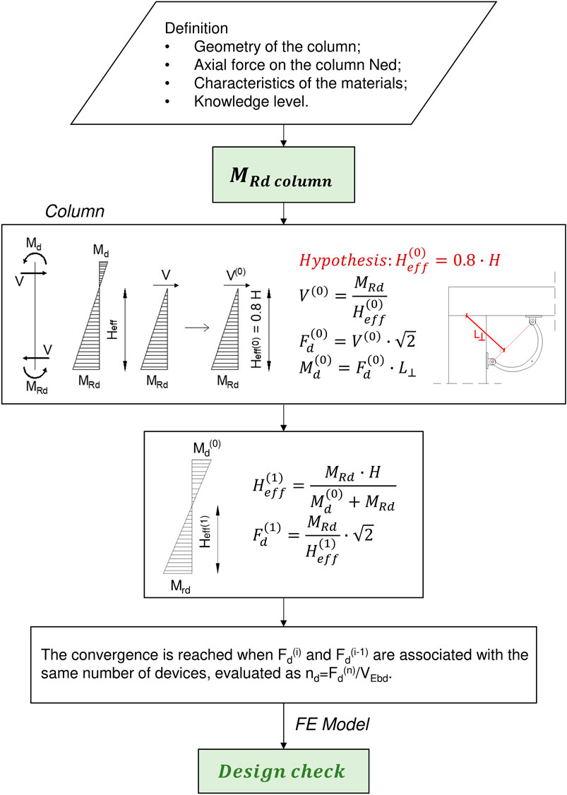
FIGURE 9. Flow chart of the design procedure.Note: L ⊥ is the distance between the line passing through the device connections and the beam rotation point at the beam-to-column interface.
The first step of the procedure is the definition of the geometry, the material characteristics and the loading on the column. The probable bending moment capacity at the base of the column, MRd, is obtained from the geometry of the element, the axial force in the column, the material characteristics and the knowledge level of the existing building and the related confidence factor. The procedure is iterative and starts from the assumption of the development of a plastic hinge at the base of the columns (MRd) and of the presence of a bending moment at the top of the column due to the additional device (Md). A first estimate of the shear V(0) and Fd(0) and Md(0) in the device (i.e., the activation force of the device, aligned to the device connecting points, Fd(0), and the bending moment at the column top, Md(0), following the scheme in Figure 8C) is calculated assuming a linear distribution of the bending moment and an inflection point (i.e., the point at zero moment) equal to 0.8 H (i.e., effective height Heff(0)). From Md(0), it is possible to recalculate the Heff from equilibrium considerations and then derive a new estimation of V(1) and Fd(1). The number of the devices nd in each beam-to-column connection is calculated with the following equation:
The convergence is reached when Fd(i) and Fd(i-1) are associated with the same number of devices.
A case study (Figure 10) has been selected to validate the proposed design methodology. The reference structure is a 4-bay single-story precast RC industrial building with span lengths equal to 20 m along the transverse y-direction and 8 m along the longitudinal x-direction. The building is considered located in an Italian region with high seismicity (L’Aquila) with soil class C (NTC, 2018) and ground acceleration on rock equal to 0.261 g.
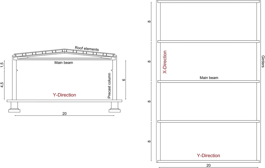
FIGURE 10. Schematic transverse frame (left) and plan view (right).
The columns have a 50 × 50 cm cross-section; the concrete class is C45/55 (45 MPa characteristic cylindrical strength at 28 days) and steel FeB°44K (characteristic yield stress, fyk, equal to 430 MPa). A reinforcement percentage equal to 0.8% in the columns has been assumed; this value is compatible with existing buildings. The average mechanical characteristics of the materials (steel and concrete) were initially defined by assuming a knowledge level equal to LC2 (NTC, 2018; KL2 in; CEN, 2005), which is associated with a confidence factor FC equal to 1.2. This leads to fcd equal to 37.5 MPa and fyd equal to 367 MPa.
Following the proposed methodology a value of Fd(1), i.e., the force required for each connection, equal to 82.3 kN is obtained. Therefore, four M1 devices were selected for each connection, with a total force equal to 95.6 kN. The design displacement of the device is assumed equal to 40 mm.
For the assessment of the in-plane behavior, a single inner portal frame of the considered building has been modeled (Figure 11A). The columns are considered fixed at the base. The plastic hinges at the base of the columns are defined in terms of moment-curvature following the modified Takeda hysteresis model in the MidasGEN (2019) software. For the definition of the plastic hinge, the mean values of the materials were used, leading to the diagram shown in Figure 11C. In each beam-to-column connection, four dissipative devices are modeled as a single non-linear spring with an elasto-plastic behavior (Figure 11B); the total stiffness is equal to 4 kN/mm (Figure 11B). The connection is modeled with a roller type constraint following the hypothesis of absence of friction between the beam and the column. The beam and column elements are modeled using beam elements. The mass at the top of the portal frame is equal to 100 t; the vertical roof load transferred to each beam-to-column connection is equal to 490.5 kN.
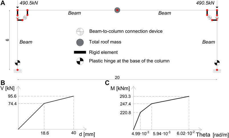
FIGURE 11. Schematic view of the finite element model (A), total force-displacement behavior of the devices (B) and moment-curvature behavior of the plastic hinge at the base of the column (C).
The in-plane validation has been carried out by means of static and dynamic non-linear analyses. Regarding non-linear static analyses, the Capacity Spectrum Method (CS) has been applied at the near collapse limit state (NCLS), according to the Italian Building Code (NTC, 2018). A horizontal force at the roof centroid was applied and the friction between beam and column was neglected.
The analysis showed that the design axial deformation of the dissipative device (40 mm) was reached for a roof lateral displacement equal to 130 mm. A bi-linearization of the capacity curve was conducted using an equal energy approach. Starting from the bi-linearized response obtained, it is possible to calculate the associated equivalent viscous damping Eq. 7.
Where Fy* and dy* are the yield force and displacement of the bi-linearized curve, respectively; Fmax* and dmax* are the maximum force and displacement of the bi-linearized curve, respectively; the coefficient k takes into account the dissipative capacity of the structure and the characteristics of the hysteresis cycle. The Italian Building Code suggests a value equal to 0.33 for low dissipative structures and 0.66 for high dissipative structures. In the current case, a k equal to 0.33 was assumed due to the limited ductility demand (equal to 2.15) reached at the design displacement. The damped elastic response spectrum corresponding to the NCLS was calculated on the basis of the viscous equivalent damping ξeq. The bi-linearized capacity curve was converted into the capacity spectrum dividing it by the mass (Figure 12 dashed red line) and placed in the acceleration-displacement response (ADRS) spectrum (Figure 12 black line). The intersection of the two curves is the performance point. In the case of no intersection the number of devices is increased.
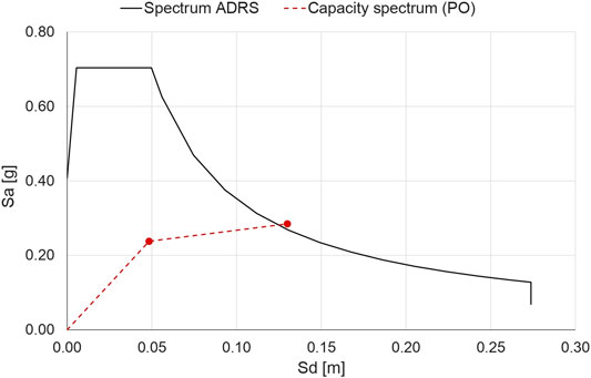
FIGURE 12. Comparison between capacity spectrum (dashed red line) and ADRS (black line) for the definition of the performance point. Note: Sa and Sd are, respectively, the pseudo acceleration and the displacement spectral values.
Response history analyses were conducted to evaluate the dynamic performance of the system. Two sets of ground motions were considered corresponding to the life safety (LSLS) and the near collapse (NCLS) limit states. Each set is composed by three spectrum-compatible ground motions obtained from the SIMQKE-1 algorithm (Venmarcke and Gasparini, 1976). Each ground motion had a duration of 30°s. Mass and Tangent stiffness Rayleigh damping was assumed based on a damping factor ξ equal to 3% for periods T1 and T2 equal to 2.0 and 0.3°s, respectively.
Figure 13 illustrates the main results expressed in terms of displacement at the top of the column (Dbeam), relative sliding at the beam-to-column interface (DrelT-P left and DrelT-P right) and axial deformation of the devices (DDevleft and DDevright).
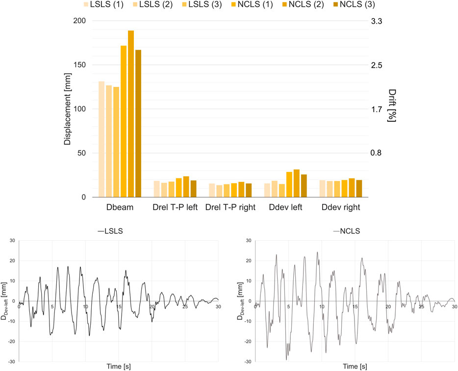
FIGURE 13. Non-linear response history analyses results.
It can be observed that the deformation of the devices is always lower than the displacement limit at NCLS equal to 40 mm for both connections.
A single column has been modeled as a fixed-end element and loaded in the transverse direction to investigate the effects of the devices on the out-of-plane performance of the system. The beam-to-column interaction (Figure 14A) only regarded the rocking of the beam in the transverse direction, while the transverse sliding was neglected (i.e., implicitly assuming a transverse constraint at the base of the beam provided for instance by RC forks). The beam-to-column devices were modeled as nonlinear springs (general links), with a hysteretic behavior defined in terms of force-displacement (Figure 11B). The devices were connected to the column through rigid elements to maintain their actual position (Figure 14). The contact between the beam and the column was modeled by two compression-only springs. The beam was modeled as a rigid element in the out-of-plane, with a lumped mass corresponding to half of the roof mass placed at the center of gravity of the roof. The gravity loads are first applied to the model as an initial load step before conducting the non-linear dynamic analyses. Second-order geometric effects were included in the model and large displacements were considered. Figure 14B shows the response history results in terms of vertical displacements of the beam centroid at the life safety (LSLS) and near collapse (NCLS) limit states. The results clearly show a reduction of the transverse rocking motion of the beam.
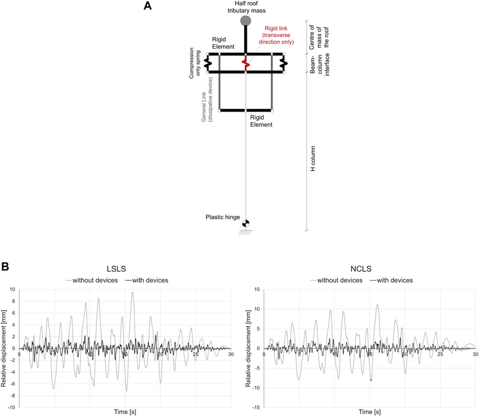
FIGURE 14. Schematic view of the finite element model (A) and response history results of the out-of-plane analysis in terms of device relative displacement (B).
This paper presented the design and application of a crescent-moon device to be applied at the beam-to-column joint of typical industrial precast reinforced concrete buildings. The device was defined on the basis of the following criteria: kinematic compatibility with the existing system (particularly referring to the beam-to-column connection), energy dissipation capacity, ease of mounting and ease of replacement after seismic events and limited interference with industrial technical systems (e.g., electrical system) often running in the longitudinal direction in close proximity to the beam-to-column joints.
Starting from the definition of the geometry of the element to avoid buckling, experimental tests and finite element analyses were carried out to verify the performance of the investigated device. The analyses allowed to verify its stability, a practically symmetrical behavior in compression and tension and the absence of buckling. On the basis of an experimental campaign, it has been possible to classify the device as “dissipative” according to EN 15129. A simple design methodology was presented and validated by means of non-linear static and non-linear response history analyses considering a precast portal frame resembling a precast industrial building. The application of the device at beam-to-column connections showed its suitability in controlling the sliding of the beam on the column (in the case of friction connections) and also the reduction of out-of-plane rocking movements. To increase the stiffness and the dissipation of the system, an additional configuration has also been presented taking advantage from a lever mechanism to increase the device displacements.
The raw data supporting the conclusions of this article will be made available by the authors upon a reasonable request.
MB: Conceptualization, Methodology, Data curation, Formal analysis, Software, Visualization, Investigation, Validation, Writing—original draft, Writing—review and editing MB: Conceptualization, Methodology, Data curation, Formal analysis, Software, Investigation AB: Conceptualization, Methodology, Visualization, Investigation, Writing—review and editing, Supervision PR: Conceptualization, Methodology, Visualization, Project administration, Writing—review and editing. Supervision. PB: Conceptualization, Writing - review and editing. All authors contributed to the article and approved the submitted version.
PB is the CEO of BIEMME srl. Biemme srl commissioned the research to develop an anti-seismic device to the University of Bergamo through a Scientific Research Contract. The single device presented herein has been certified following UNI EN 15129 under the name ‘Mezzaluna M1’. The remaining authors declare the absence of any commercial or financial relationships that could be construed as a potential conflict of interest.
The results presented in the paper are the output of such a contract.
Belleri, A., Cornali, F., Passoni, C., Marini, A., and Riva, P. (2017a). Evaluation of out-of-plane seismic performance of column-to-column precast concrete cladding panels in one-storey industrial buildings. Earthq. Eng. Struct. Dyn. 47, 397–417. doi:10.1002/eqe.2956
Belleri, A., Marini, A., Riva, P., and Nascimbene, R. (2017b). Dissipating and re-centring devices for portal-frame precast structures. Eng. Struct. 150, 736–745. doi:10.1016/j.engstruct.2017.07.072
Belleri, A. (2017). Displacement based design for precast concrete frames with not-emulative connections. Eng. Struct. 141, 228–240. doi:10.1016/j.engstruct.2017.03.020
Belleri, A., and Riva, P. (2012). Seismic performance and retrofit of precast concrete grouted sleeve connections. Pci. J. 57 (1), 97–109. doi:10.15554/pcij.01012012.97.109
Belleri, A., Torquati, M., Marini, A., and Riva, P. (2016). Horizontal cladding panels: in-plane seismic performance in precast concrete buildings. Bull. Earthq. Eng. 14, 1103–1129. doi:10.1007/s10518-015-9861-8
Belleri, A., Brunesi, E., Nascimbene, R., Pagani, M., and Riva, P. (2015a). Seismic performance of precast industrial facilities following major earthquakes in the Italian territory. J. Perform. Constr. Facil. 29 (5), 04014135. doi:10.1061/(ASCE)CF.1943-5509.0000617
Belleri, A., Torquati, M., Riva, P., and Nascimbene, R. (2015b). Vulnerability assessment and retrofit solutions of precast industrial structures. Earthq. Struct. 8 (3), 801–820. doi:10.12989/eas.2015.8.3.801
Bosio, M., Belleri, A., Riva, P., and Marini, A. (2020). Displacement-based simplified seismic loss assessment of Italian precast buildings. J. Earthq. Eng. 24 (1), 60–81. doi:10.1080/13632469.2020.1724215
Bournas, D. A., Negro, P., and Taucer, F. F. (2014). Performance of industrial buildings during the Emilia earthquakes in Northern Italy and recommendations for their strengthening. Bull. Earthq. Eng. 12 (5), 2383–2404. doi:10.1007/s10518-013-9466-z
Brunesi, E., Nascimbene, R., Bolognini, D., and Bellotti, D. (2015). Experimental investigation of the cyclic response of reinforced precast concrete framed structures. Pci. J. 60 (2), 57–79. doi:10.15554/pcij.03012015.57.79
Casotto, C., Silva, V., Crowley, H., Nascimbene, R., and Pinho, R. (2015). Seismic fragility of Italian RC precast industrial structures. Eng. Struct. 94, 122–136. doi:10.1016/j.engstruct.2015.02.034
CEN (2005). EN 1998‐3:2005. Eurocode 8: Design of structures for earthquake resistance, part 3: Assessment and retrofitting of buildings. Brussels, Belgium: European Committee for Standardization. Available at: 305/2011Directive 98/34/EC, Directive 2004/18/EC.
Dal Lago, B., Negro, P., and Dal Lago, A. (2018). Seismic design and performance of dry-assembled precast structures with adaptable joints. Soil Dyn. Earthq. Eng. 106, 182–195. doi:10.1016/j.soildyn.2017.12.016
Dal Lago, B., Toniolo, G., and Lamperti Tornaghi, M. (2016). Influence of different mechanical column-foundation connection devices on the seismic behaviour of precast structures. Bull. Earthq. Eng. 14 (12), 3485–3508. doi:10.1007/s10518-016-0010-9
Demartino, C., Vanzi, I., Monti, G., and Sulpizio, C. (2018). Precast industrial buildings in Southern Europe: loss of support at frictional beam-to-column connections under seismic actions. Bull. Earthq. Eng. 16, 259–294. doi:10.1007/s10518-017-0196-5
Ercolino, M., Bellotti, D., Magliulo, G., and Nascimbene, R. (2018). Vulnerability analysis of industrial RC precast buildings designed according to modern seismic codes. Eng. Struct. 158, 67–78. doi:10.1016/j.engstruct.2017.12.005
Ercolino, M., Magliulo, G., and Manfredi, G. (2016). Failure of a precast RC building due to Emilia-Romagna earthquakes. Eng. Struct. 118, 262–273. doi:10.1016/j.engstruct.2016.03.054
Francavilla, A. B., Latour, M., Piluso, V., and Rizzano, G. (2020). Design criteria for beam-to-column connections equipped with friction devices. J. Constr. Steel Res. 172, 106240. doi:10.1016/j.jcsr.2020.106240
Hsu, H.-L., and Halim, H. (2017). Improving seismic performance of framed structures with steel curved dampers. Eng. Struct. 130, 99–111. doi:10.1016/j.engstruct.2016.09.063
Iervolino, I., Spillatura, A., and Bazzurro, P. (2019). “RINTC-e project: towards the assessment of the seismic risk of existing buildings in Italy, RINTC-e: towards seismic risk assessment of existing residential reinforced concrete buildings in Italy,” in 7th ECCOMAS Thematic Conference on Computational Methods in Structural Dynamics and Earthquake Engineering, Crete, Greece, June 24–29, 2019.
Magliulo, G., Cimmino, M., Ercolino, M., and Manfredi, G. (2017). Cyclic shear tests on RC precast beam-to-column connections retrofitted with a three-hinged steel device. Bull. Earthq. Eng. 15 (9), 3797–3817. doi:10.1007/s10518-017-0114-x
Magliulo, G., Ercolino, M., Petrone, C., Coppola, O., and Manfredi, G. (2014). The Emilia earthquake: seismic performance of precast reinforced concrete buildings. Earthq. Spect. 30 (2), 891–912. doi:10.1193/091012EQS285M
Minghini, F., Ongaretto, E., Ligabue, V., Savoia, M., and Tullini, N. (2016). Observational failure analysis of precast buildings after the 2012 Emilia earthquakes. Earthq. Struct. 11 (2), 327–346. doi:10.12989/eas.2016.11.2.327
Nastri, E., Vergato, M., and Latour, M. (2017). Performance evaluation of a seismic retrofitted R.C. precast industrial building. Earthq. Structu. 12 (1), 13. doi:10.12989/eas.2017.12.1.013
NTC (2018). Aggiornamento delle “Norme tecniche per le costruzioni”. Italy: Decreto Ministeriale del.
OPCM 3274. (2003). Primi elementi in materia di criteri generali per la classificazione sismica del territorio nazionale e di normative tecniche per le costruzioni in zona sismica. Italy: Presidente Del Consiglio Dei Ministri.
Palanci, M., Senel, S. M., and Kalkan, A. (2017). Assessment of one story existing precast industrial buildings in Turkey based on fragility curves. Bull. Earthq. Eng. 15 (1), 271–289. doi:10.1007/s10518-016-9956-x
Palermo, M., Silvestri, S., Gasparini, G., and Trombetti, T. (2015). Crescent shaped braces for the seismic design of building structures. Mater. Struct. 48, 1485–1502. doi:10.1617/s11527-014-0249-z
Pollini, A. V., Buratti, N., and Mazzotti, C. (2020). Behavior factor of concrete portal frames with dissipative devices based on carbon-wrapped steel tubes. Bull. Earthq. Eng. 19, 553. doi:10.1007/s10518-020-00977-y
Santos, A. F., Santiago, A., Latour, M., and Rizzano, G. (2019). Analytical assessment of the friction dampers behaviour under different loading rates. J. Constr. Steel Res. 158, 443–459. doi:10.1016/j.jcsr.2019.04.005
Timoshenko, S. P., and Gere, J. M. (2009). Theory of elastic stability. Mineola, NY: Dover Publications Inc. Dover Civil and Mechanical Engineering.
Keywords: precast industrial buildings, crescent moon-shaped device, beam-to-column connection, seismic retrofit, energy dissipation
Citation: Bressanelli ME, Bosio M, Belleri A, Riva P and Biagiotti P (2021) Crescent-Moon Beam-To-Column Connection for Precast Industrial Buildings. Front. Built Environ. 7:645497. doi: 10.3389/fbuil.2021.645497
Received: 23 December 2020; Accepted: 05 February 2021;
Published: 18 March 2021.
Edited by:
Arturo Tena-Colunga, Autonomous Metropolitan University, MexicoReviewed by:
Massimo Latour, University of Salerno, ItalyCopyright © 2021 Bressanelli, Bosio, Belleri, Riva and Biagiotti. This is an open-access article distributed under the terms of the Creative Commons Attribution License (CC BY). The use, distribution or reproduction in other forums is permitted, provided the original author(s) and the copyright owner(s) are credited and that the original publication in this journal is cited, in accordance with accepted academic practice. No use, distribution or reproduction is permitted which does not comply with these terms.
*Correspondence: Andrea Belleri, YW5kcmVhLmJlbGxlcmlAdW5pYmcuaXQ=
Disclaimer: All claims expressed in this article are solely those of the authors and do not necessarily represent those of their affiliated organizations, or those of the publisher, the editors and the reviewers. Any product that may be evaluated in this article or claim that may be made by its manufacturer is not guaranteed or endorsed by the publisher.
Research integrity at Frontiers
Learn more about the work of our research integrity team to safeguard the quality of each article we publish.