 Ming Chian Yew
 Ming Kun Yew2
94% of researchers rate our articles as excellent or good
Learn more about the work of our research integrity team to safeguard the quality of each article we publish.
Find out more
ORIGINAL RESEARCH article
Front. Built Environ. , 19 February 2021
Sec. Indoor Environment
Volume 7 - 2021 | https://doi.org/10.3389/fbuil.2021.641041
This article is part of the Research Topic Cool Roofing Technologies for Sustainable Buildings View all 5 articles
This paper presents a novel cool roof technology system that promotes both passive and active cooling methods in reducing the attic temperature of the building. The project aimed to evaluate the effect of various roof model designs on the heating load to establish the capacity of a cooling roof system by maintaining the thermal comfort level for occupants in the buildings. There are four main components in constructing the cool roof models: 1) metal deck roof, 2) lightweight foam concrete roof, 3) moving-air-cavity (MAC) ventilation, and 4) solar-powered fan. Four small-scale cool roof models were built to evaluate the performance of each cool roof design. The performances of the roof surface and attic temperatures of each designed cool roof models were compared with the conventional metal deck roof. The roof models were conducted indoors by using halogen spotlights. The result of the Roof Design IV with the integration of lightweight foam concrete, MAC, and solar-powered fans has effectively reduced the attic temperature by 6.0°C compared with the normal roof model (Roof Design I). As a result, this integrated cool roof design comprises the ability to enhance the comfortability of occupants toward long-term sustainable development with the utilization of renewable energy to protect the natural environment.
Many recent studies have focused on green building with interest in cool roof technology. A cool roof is a roof that absorbs less heat and reflects more sunlight than a standard roof, lowering roof temperature and transferring less heat into the space of the attic and room. While the benefits of cool roofs are more significant in hotter climates, their advantages can also extend into the Western Hemisphere, tropical countries including Mexico, all of Central America, all of the Caribbean islands from just south of Nassau in the Bahamas, and the top half of South America for various commercial and industrial buildings (Bianchini and Hewage, 2012).
Malaysia is a developing Southeast Asian country, which is located just north of the Equator. Malaysia’s economic growth had greatly increased the country’s energy consumption. The highest daily electricity demand for Malaysia hit 17,788 MW on april 19, 2016 after a record of 17,175 MW on March 9, 2016 (Hasan, 2017). The rise in the population of Malaysia has led to the increasing demand for residential housing and industrial buildings. Malaysia averagely will have 27
Most of the buildings in Malaysia were constructed close to each other especially in the city area, which causes poor ventilation between the buildings. Moreover, the hot climate results in a high indoor temperature when the solar radiation hits the roof and wall of the buildings, which increases the demand for air conditioners. The main component of a building that receives the most amount of solar radiation is the roof. The roof is located at the most high-up of a building and is covered by a gypsum ceiling board before the inner place of a house. In Malaysia, most general roof materials in the houses and factories are concrete roof tiles (85%), clay roof files (10%), and metal deck (5%) (Yew et al., 2013). Additionally, a black roof surface temperature can exceed up to 87.8°C when exposed to full sunlight, especially in countries with hot climates (Yew et al., 2018).
For a building, the highest temperature takes place in the attic region. The attic region is the space below the roof and above the building’s ceiling board. When the roof absorbs the solar radiation during the daytime, the heat is transferred into the attic region through conduction. The heat is then trapped inside the attic region due to the airtight design of the conventional roof. The prohibition of entering air of a conventional roof design is the main cause of high temperature recorded in the attic region. The heat is then transferred to the inner building, which results in a hot indoor atmosphere. The attic will always have higher temperature compared to the living space (Zhao et al., 2019).
A few cool roof systems were designed and developed by researchers to reduce the building’s energy consumption on keeping the building cool (Romeo and Zinzi, 2013). A cool roof system is one of the modern substantial energy reduction approaches. When the overall temperature of the attic region is reduced, the temperature inside the building would be directly reduced, which causes the lowering of cooling load. A cool roof system promotes attic ventilation, the cool ambient air is being drawn in, and the hot trapped air is being drawn out. When the cool ambient air reaches the attic region and mixes with the air inside, the air temperature can be effectively reduced at day time, which results in a lower transfer of heat from the attic region to the living space (Zhao et al., 2019).
The cool roof system has a radiative surface, which facilitates the solar reflection. Moreover, the cool roof system consists of a few radiative air coolers linked in a parallel manner to promote heat transmission (Zhao et al., 2019). Overall, a cool roof is an upgraded roof design composed of passive and active cool roof systems (Yew and Yew, 2021). A cool roof can benefit the environment such as reducing the urban island effect with the cooler outside air, lessening power plant emissions by reducing air conditioning demand, which decreases the greenhouse gases and other air pollutants from the burned fossil fuels, and slowing climate change as cool roofs decrease heat absorbed on the Earth’s surface (Macintyre and Heaviside, 2019). Most of the roofs in industrial buildings such as factories and warehouses are built using metal deck roofing that leads to rising of the roof, attic, and indoor temperatures when exposed to full sunlight in the afternoon. In this project, the designed cool roof roofing technology system makes use of the solar-powered fan, moving-air-cavity (MAC), and lightweight foam concrete roofing to reduce the attic temperature toward an eco-friendly and sustainable roof design, which has not been studied by other researchers.
The main goal of this study is to evaluate a system that combines innovative lightweight foam concrete roof with aluminum tubes for cavity ventilation and solar-powered fan to optimize the performance of the novel roofing system in terms of heat reflection and heat rejection. The performance will be assessed by evaluating the various temperatures of the roof, aluminum channel, and attic. The aim will be to obtain lower attic temperatures that will result in a more comfortable living environment.
Four small-scale roof models representing the different roof system designs were built to evaluate the resistance to heat gain. Components that were tested included the lightweight foam concrete roof, MAC ventilation, and solar-powered fan. The performance of the four designs 1) metal deck roof coated with normal paint without MAC (Design I), 2) lightweight foam concrete without MAC (Design II), 3) combination of lightweight foam concrete with MAC (Design III), and 4) combination of lightweight foam concrete with MAC and solar-powered fan (Design IV) were studied and compared.
The basic model of the cool roof system is the attic region. The basic model was built by using Perspex of 5 mm thickness and covered by a metal deck roofing [dimensions: 450 mm (L) × 380 mm (W) × 1.5 mm (D)] with a thermal conductivity of 45.3 W/mK. The dimensions of the basic model were 340 mm in length, 360 mm in width, and 490 mm in height. Figure 1 shows the dimensions of the basic model with a roof area of 412 mm in length and 340 mm in width inclined at an angle 30°.
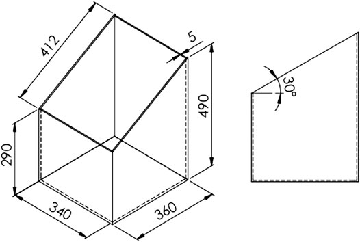
FIGURE 1. The dimensions of basic cool roof model (all units in mm).
The lightweight foam concrete tile was constructed with a targeted density of 1,250 kg/m3, and its thermal conductivity value is 0.61 W/m.K. The base mix mass was 6.6 kg, and the foam density was 50 kg/m3. The cement paste was added with 0.5% calcium stearate and 2.6% of eggshell. The final dimensions of lightweight foam concrete tile after curing was 460 mm in length, 360 mm in width, and 30 mm in height.
The MAC was located underneath the roof and above the attic region. The surface of the MAC was built with an aluminum sheet. The channel inside the MAC was built with aluminum foil as shown in Figure 2. The structure was supported by a steel rod.
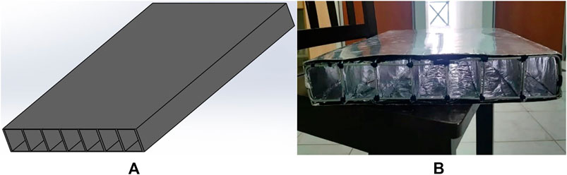
FIGURE 2. The diagram of moving-air-cavity (MAC). (A) SolidWorks (B) Experimental.
The cavity, which is surrounded by aluminum foil acts as a heat radiant reflector. The thickness of lightweight foam concrete roof was 46 mm. The design and dimension of MAC and lightweight foam concrete roof are presented in Figure 3.
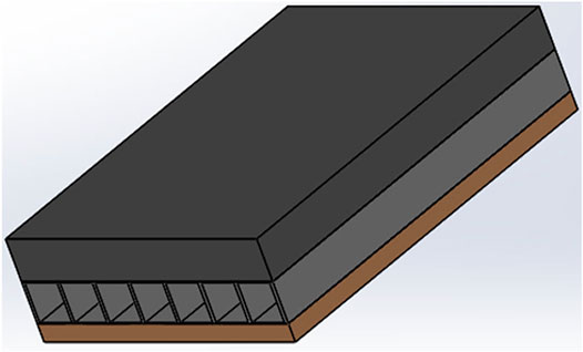
FIGURE 3. The lightweight foam concrete roof with MAC ventilation.
Since the channels were separated into seven by aluminum foil and steel rod, the channels acted as the tubes for heat exchange to maintain the cool temperature in the attic. The air channel of 43 mm wide allowed 3 mm of tolerance when 40 × 40-mm-sized solar-powered fans were installed.
Seven solar-powered fans of dimensions 4 cm
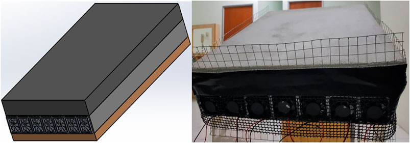
FIGURE 4. The solar-powered fans attached to MAC (left) SolidWorks (right) experimental.
The air channel with uniform parallel design maximized the amount of air in the MAC. Air can act as a thermal insulation element to stop the heat conducted through the roof from transferring downward to the attic. The departmentalized design of MAC followed the dimension of solar-powered fans. It is to ensure that all the cool air induced by the solar-powered fans enter the MAC completely. Each solar-powered fan had an air channel to prevent the flow interruption from the other solar-powered fans, which slowed down the rate of airflow and the heat transfer.
The halogen spotlight acted as a source of sunlight in this project. The temperature of the surrounding indoor air was nearly 30.5°C before the test. The lamp provided the necessary heat source for the roof warming and the light source for the solar panel. In this project, two 500-W halogen spotlights were placed 45° from the vertical axis and the distance of the lamps and roof surface was fixed at 30 cm as shown in Figure 5.
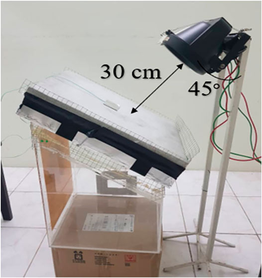
FIGURE 5. The halogen spotlight setup.
Four temperature sensors of K-type thermocouple were used at the assigned location and set up as shown in Figure 6. The first thermocouple A was taped using aluminum tape on the roof surface for all the roof designs to measure the roof temperature. The second thermocouple B was placed 200 mm vertically downwards from thermocouple A, and it was used to measure the attic temperature.
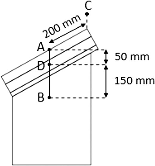
FIGURE 6. The thermocouple setup.
Then, the third thermocouple C was used to measure the surrounding indoor air temperature before conducting the test. D was placed at the MAC. Last, the thermocouple D was used at all roof designs except roof Designs I and II. The data were recorded every 1 min for a total experiment duration of 30 min.
The experimental setup was divided into roof setup, halogen spotlight setup, and temperature sensor setup. This project had four roof models, the normal metal deck (Design I), foam concrete roof (Design II), foam concrete roof with MAC (Design III), and foam concrete roof with MAC and solar-powered fans (Design IV), and are shown in Figure 7. The four roof models were conducted, and their roof performances and attic temperatures were compared.
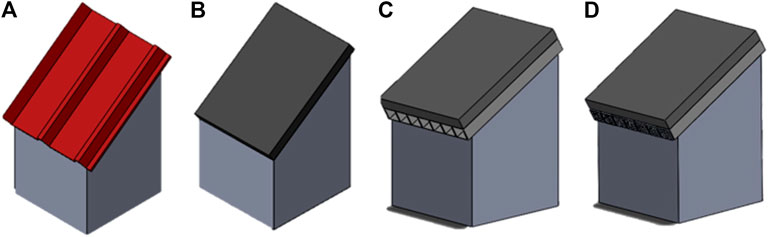
FIGURE 7. The roof model designs (A) I (B) II (C) III, and (D) IV.
The heat transfer process is important in the analysis of a cool roof system. The heat emitted by the Sun radiation reach the roof surface and enter the attic region by conduction process.
Figure 8 shows the mechanism of heat transfer in a cool roof system. The practice of two control volumes,
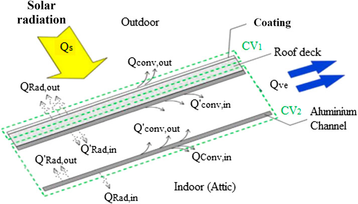
FIGURE 8. The mechanism of heat transfer of the cool roof system.
The flow of heat from the ambient surrounding to the roof, attic, and inner space is proved by the second law of thermodynamics. The second law of thermodynamics declared the moving of heat from high temperature to low temperature. Equations 1, 2 are generated by the conservation of energy at control volumes
where,
where,
From Equation 1, the heat absorbed by the roof due to the heat emitted from the Sun can be reflected away by the reflectivity of the roof coating by radiation and convection. The presence of coating prevents the full amount of heat absorbed by the roof from transferring into the roof cavity by conduction of the metal deck.
From Equation 2, the heat that is not reflected away at the first control volume now acts as the heat input to the roof cavity. The heat then dissipated to the attic region by radiation and convection. By the design of the moving-air-cavity, a portion of the heat is removed instead of dissipated into the attic region. The moving-air-cavity, the aluminum channel, provides a space for the heat to move up and finally be removed to the surroundings by the second law of thermodynamics. The heat removal rate of the moving-air-cavity is expressed in Eq. 3.
where,
The experiment was started with a controlled experiment roof model composed solely of a conventional red metal deck. Figure 9 shows the results obtained and presented in a graph of temperature vs. time for a total experiment duration of 30 min.
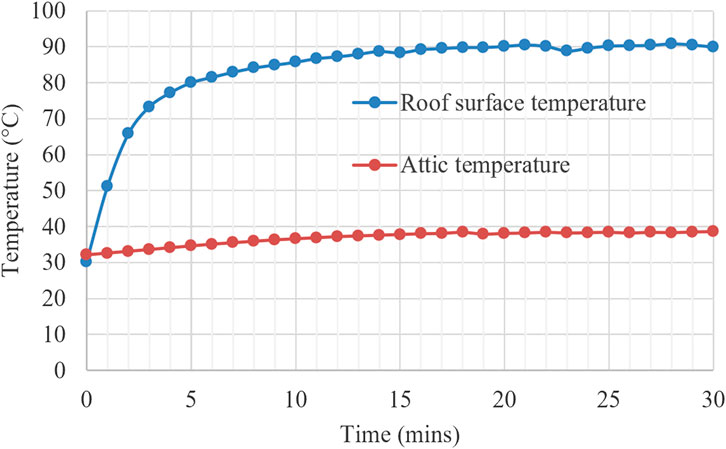
FIGURE 9. Performance of metal deck roof.
Results show that the maximum temperatures of the roof surface and attic were 90.8°C and 38.6°C, respectively. The roof temperature become constant after 13 min of testing. The maximum difference in temperature between the attic and roof upper surface was 51.3°C at 30 min. The rate of roof temperature increase was 14.36°C/min in the first 3 min. The rapid increase was due to the low reflectivity and high thermal conductivity of the normal coating on the metal deck roof surface. The temperature increase rate proves the high thermal conductivity of the metal deck, which is at 44.8 W/mK (Singh et al., 2016).
For attic temperature variation, the maximum of attic temperature was about 38.6°C at 30 min and the increase rate was 0.2167°C/min. This outcome is proven when the metal deck roof is used; the house structure is maintained as hot as the ambient temperature. The natural ventilation did not carry the heat away as the metal roof is like an opened roof, the heat can penetrate into the building directly and immediately.
The experiment was continued with the metal roof removed and replaced with a lightweight foam concrete roof, a more practical roof design approach. Figure 10 shows the result obtained and presented in a graph of temperature vs. time for the roof Design II.
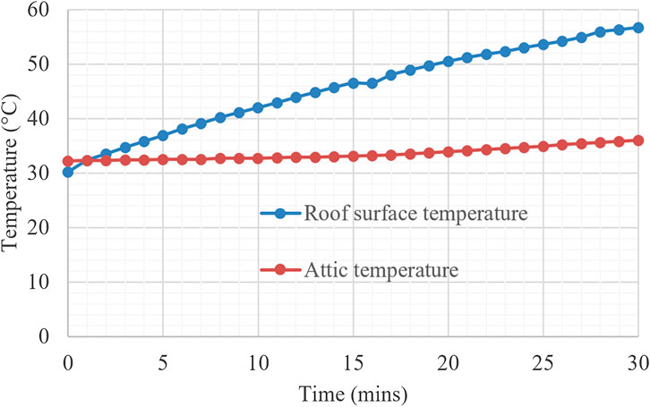
FIGURE 10. Performance of lightweight foam concrete roof.
For the roof surface temperature, the temperature increased slowly throughout the experiment when the roof was replaced with foam concrete. The metal deck roofing had steep gradient, which is about 14.36°C/min at the first 3 min when exposed to the spotlight. However, the lightweight foam concrete reached 1.65°C/min only during the first 2 min of testing.
The maximum roof surface temperature achieved by foam concrete roof was 56.7°C, which was 34.1°C lower than the metal roof. This can be proven by the foam concrete’s lower thermal conductivity and thermal absorptivity. The foam concrete’s thermal conductivity limits from 0.24 to 0.74 W/mK due to the existence of voids (Ganesan et al., 2015). The roof is the major solar heat collector where 40% of the energy would be consumed for top-floor buildings; hence, the roof material is an essential element for the cool roofing system (Gao et al., 2017). By utilizing the lightweight foam concrete in the building design, it can reduce the amount of heat trapped at the roof surface.
For the attic temperature, the maximum temperature recorded was 36.0°C, which was lower than the metal decks by 2.6°C. The average increase rate of attic temperature was 0.1267°C/min, which was lower than the metal decks by 0.09°C/min. Foam concrete roof is a better heat insulator than metal roof; hence, the attic region had a lower temperature increase rate despite the higher ambient temperature.
The experiment was continued with the implementation of MAC with foam concrete roof model. Figure 11 shows the result obtained and presented in a graph of temperature vs. time for roof Design III.
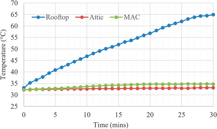
FIGURE 11. Performance of lightweight foam concrete roof with MAC.
The roof surface temperature increased slowly as shown in Figure 11 due to the low thermal conductivity of foam concrete and reached a maximum recorded temperature of 67.0°C and increased rate of 1.1333°C/min. The maximum recorded temperature was 23.8°C, which was 11.1°C lower than that of the metal decks. The highest attic temperature recorded was 33.1°C, which was 2.9°C lower than that of the foam concrete without MAC. For the attic temperature, the average increase rate of 0.03°C/min was 0.0967°C/min lower than that of the foam concrete without MAC.
By adding the MAC underneath the foam concrete roof, the average attic temperature increase rate showed a decrease of 76.32%. This proved the efficiency of MAC’s parallel radiative air cooler in promoting the heat transmission and flowing rate. With this high emissive material, the heat is transferred back to the surrounding continuously, which then executed the passive cooling (Chen and Lu, 2020).
The experiment was continued with the implementation of solar-powered fans integrated with MAC and lightweight foam concrete roof. Figure 12 shows the results obtained and presented in a graph of temperature vs. time for roof Design IV.
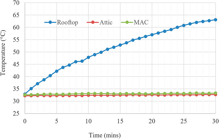
FIGURE 12. Performance of lightweight foam concrete roof with MAC and solar-powered fans.
For roof surface temperature, the maximum temperature recorded was 63.9°C for roof Design IV, which was 3.1°C lower than that of roof Design III. The roof temperature increase rate was 1.0333°C/min, which was 0.01°C/min lower than that of roof Design III. The highest recorded attic temperature and the average attic temperature increase rate were 32.7°C and 0.0167°C/min, which were 0.4°C and 0.0133°C/min lower than the roof without solar-powered fans.
At this experiment, three halogen spotlights were used instead of two spotlights as in the previous experiment due to the third spotlight being used to supply solar power to solar-powered fans. The low attic temperature had proved the efficiency of solar-powered fans with an expected airflow rate of 0.68 m/s in removing the heat at the air channel inside of MAC to keep the attic cool (Yew et al., 2018).
Moreover, the attic temperature increase rate had shown a decrease of 92.29% when compared with the normal metal roof. This amount of decrease had improved by 15.97% when solar-powered fans were implemented in this MAC. Air circulation is important in keeping the attic cool by channeling out the heat (Sun et al., 2013). Solar-powered fans had successfully kept the model cool and maintained at a temperature lower than the ambient by active approach with the combination of the thermal break at the MAC.
Results show that the attic temperature increased rapidly when metal deck roof was applied in roof Designs I. Then, when foam concrete roof was applied solely in roof Design II without the MAC and solar-powered fans, the attic temperature increased slower but did not set down at any temperature, although the gradient is lower than the metal deck roof. However, after the MAC was introduced at roof Design III, the attic temperature performed a steady variation. Table 1 shows the average attic temperature increasing rate for each of the roof designs.
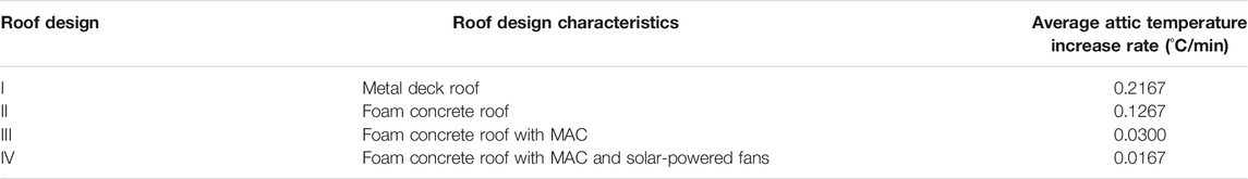
TABLE 1. The average attic temperature increase rate for different roof designs.
Without the MAC, the lightweight foam concrete roof solely had an average attic temperature increase rate of 0.1267°C/min. After the MAC was added, it dropped to 0.03 °C/min, which was a decrease of 76.32%. The MAC promoted passive radiative cooling. Passive radiative cooling dissipated extra heat to the surroundings through the structure’s outlet without the need for power input (Liu, et al., 2020). The material of silver coating on the aluminum foil possessed 97% of solar reflectivity and 96% of infrared emissivity (Gentle and Smith, 2015). In this experiment, passive radiative cooling was achieved by silver color coating on the aluminum sheet in the MAC. Heat is dissipated and removed effectively from MAC due to the fantastic heat emissivity characteristics of MAC.
Without the solar-powered fans, the average attic temperature increase rate was 0.03°C/min in roof Design III. After the solar-powered fans were added in roof Design IV, it fell to 0.0167°C/min. The solar-powered fans work as the active cooling system to improve the MAC ventilation. With the combination of passive radiative cooling and active solar-powered fans, the attic temperature achieved the lowest temperature increase rate at 0.0167°C/min for roof Design IV.
The conventional metal deck roof was compared with a new cool roof system. The cool roofing system combined the integration of foam concrete roof with the implementation of MAC and solar-powered fans. The MAC implemented a high reflectivity surface, which promoted radiative cooling. The solar-powered fans had improved the mass flow of air for better heat transfer between ambient air and heat trapped in the roof. The performance of each roof design is summarized in Table 2. The roof Design IV had the lowest attic temperature and maintained the coolest attic among all roof models.
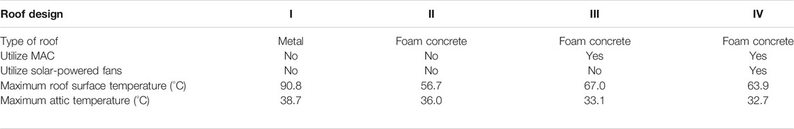
TABLE 2. Summary of the performances of the different roof designs.
The metal deck roof model showed the highest roof surface temperature of 90.8°C. The metal deck roof was then replaced by foam concrete roof, which has reduced the attic temperature by up to 2.7°C from 38.7°C to 36.0°C. This proved that the ability of lightweight foam concrete roof performed as the roof insulator due to its lower thermal conductivity. The heat is transferred slower in foam concrete tile, which has lesser heat conducted through the roof and enter the attic region.
Then, the MAC was installed underneath the foam concrete roof. The attic temperature then further reduced the attic temperature up to 2.9°C (from 36°C to 33.1°C) compared with the foam concrete roof without the MAC. The roof design with MAC showed a decrease of 5.6°C in the attic region compared with the original metal roof. MAC’s radiative silver surface of high emissivity properties increases the heat dissipation rate, thus acting as the passive radiative cooling.
Last, the solar-powered fans were introduced at the inlets of MAC, which further reduced the attic temperature by 6.0°C (from 38.7°C to 32.7°C) compared with the normal metal roof. The maximum attic temperature achieved was 32.7°C. Solar-powered fans were the active cooling approach by increasing the mass of air in the air channel and promoting the dynamic air circulation. The heat is thus removed through the air channels in MAC effectively with the integration of the active cooling. This roof design with foam concrete roof integrated with MAC and solar-powered fans performed the most stable and coolest attic temperature. The attic temperature remained unchanged for the last 10 min, and it is the only roof design with this stabilizing performance that keeps the attic cool. The mechanism of the heat transfer of the integrated cool roof system is described in the Section 2.7 for more details.
In this project, the main objective is to design an integration cool roof system to reduce the temperature in the attic by using effective roofing materials, MAC ventilation, and sustainable solar. A total of four roof design models with different active and passive cool roof systems were fabricated and carried out indoors. The combination of lightweight foam concrete roof, MAC, and solar power demonstrated the best performance among these four cool roof models. A total temperature reduction of about 6°C in the attic is achieved compared with a normal metal deck roofing (Design I). In addition, integration of MAC-solar powered fans had resulted in the reduction of about 2.9°C compared with the MAC system. In general, the combination of lightweight foam concrete roof with MAC and solar-powered fans has proven to be effective in improving the comfort of building occupants with the passive and active cooling approaches.
The raw data supporting the conclusions of this article will be made available by the authors, without undue reservation.
MY supervised the project. MH conducted the experimental work. MH wrote the original manuscript. MY and LS analyzed and edited the manuscript. MY proofread the manuscript. All authors contributed to the manuscript revision and approved the submitted version of the manuscript.
Funding from Final Year Project budget.
The authors declare that the research was conducted in the absence of any commercial or financial relationships that could be construed as a potential conflict of interest.
We gratefully acknowledge the laboratory facilities support and final year project funding from Lee Kong Chian, Faculty of Engineering and Science, Universiti Tunku Abdul Rahman.
Bianchini, F., and Hewage, K. (2012). How “green” are the green roofs? Lifecycle analysis of green roof materials. Build. Environ. 48, 57–65. doi:10.1016/j.buildenv.2011.08.019
Chen, J., and Lu, L. (2020). Comprehensive evaluation of thermal and energy performance of radiative roof cooling in buildings. J. Build. Eng. 33, 101631. doi:10.1016/j.jobe.2020.101631
Ganesan, S., Othuman Mydin, M. A., Mohd Yunos, M. Y., and Mohd Nawi, M. N. (2015). Thermal properties of foamed concrete with various densities and additives at ambient temperature. Appl. Mech. Mater. 747, 230–233. doi:10.4028/www.scientific.net/AMM.747.230
Gao, Y., Shi, D., Levinson, R., Guo, R., Lin, C., and Ge, J. (2017). Thermal performance and energy savings of white and sedum-tray garden roof: a case study in a Chongqing office building. Energy Build. 156, 343–359. doi:10.1016/j.enbuild.2017.09.091
Gentle, A. R., and Smith, G. B. (2015). A subambient open roof surface under the mid-summer sun. Adv. Sci. 2 (9), 1500119. doi:10.1002/advs.201500119
Hasan, A. F. (2017). Smarter consumers malaysia volume 11. Available at: https://www.st.gov.my/ms/contents/publications/energyMalaysia/Energy (Accessed April 19, 2020).
Liu, J., Zhang, D., Jiao, S., Zhou, Z., Zhang, Z., and Gao, F. (2020). Preliminary study of radiative cooling in cooling season of the humid coastal area. Sol. Energy Mater. Sol. Cell. 208, 110412. doi:10.1016/j.solmat.2020.110412
Macintyre, H. L., and Heaviside, C. (2019). Potential benefits of cool roofs in reducing heat- related mortality during heatwaves in a European city. Environ. Int. 127, 430–441. doi:10.1016/j.envint.2019.02.065
Ooi, J. B., Lockard, C. A., Leinbach, T. R., and Ahmad, Z. B. (2020). Malaysia facts, geography, history, and points of interest britannica [Online]. Available at: https://www.britannica.com/place/Malaysia (Accessed April 19, 2020).
Romeo, C., and Zinzi, M. (2013). Impact of a cool roof application on the energy and comfort performance in an existing non-residential building. A Sicilian case study. Energy Build. 67, 647–657. doi:10.1016/j.enbuild.2011.07.023
Singh, M., Gulati, R., Srinivasan, R., and Bhandari, M. (2016). Three-dimensional heat transfer analysis of metal fasteners in roofing assemblies. Buildings 6 (4), 49. doi:10.3390/buildings6040049
Sun, Y., Wang, S., and Xiao, F. (2013). Development and validation of a simplified online cooling load prediction strategy for a super high-rise building in Hong Kong. Energy Convers. Manag. 68, 20–27. doi:10.1016/j.enconman.2013.01.002
Yew, M. C., Ramli Sulong, N. H., Chong, W. T., Poh, S. C., Ang, B. C., and Tan, K. H. (2013). Integration of thermal insulation coating and moving-air-cavity in a cool roof system for attic temperature reduction. Energy Convers. Manag. 75, 241–248. doi:10.1016/j.enconman.2013.06.024
Yew, M. C., and Yew, M. K. (2021). “Chapter: 12–Active and passive systems for cool roofs,” in Fernando pacheco-torgal, lech czarnecki, anna laura pisello, luisa F. Cabeza, claes-göran GranqvistWoodhead publishing series in civil and structural engineering. Eco-efficient materials for reducing cooling needs in buildings and construction. (Oxford, United Kingdom: Woodhead Publishing), 275–288.
Yew, M. C., Yew, M. K., Saw, L. H., Ng, T. C., Chen, K. P., Durairaj, R., et al. (2018). Experimental analysis on the active and passive cool roof systems for industrial buildings in Malaysia. J. Build. Eng. 33, 134–141. doi:10.1016/j.jobe.2018.05.001
Keywords: solar, moving-air-cavity, attic temperature, sustainable building, global warming
Citation: Yew MC, Yew MK, Ho ML and Saw LH (2021) Integration of Lightweight Foam Concrete Roof, Moving-Air-Cavity, and Solar-Powered Fans for Attic Temperature Reduction. Front. Built Environ. 7:641041. doi: 10.3389/fbuil.2021.641041
Received: 13 December 2020; Accepted: 11 January 2021;
Published: 19 February 2021.
Edited by:
Zhenjun Ma, University of Wollongong, AustraliaReviewed by:
Jiachen Zhang, California Air Resources Board, United StatesCopyright © 2021 Yew, Yew, Ho and Saw. This is an open-access article distributed under the terms of the Creative Commons Attribution License (CC BY). The use, distribution or reproduction in other forums is permitted, provided the original author(s) and the copyright owner(s) are credited and that the original publication in this journal is cited, in accordance with accepted academic practice. No use, distribution or reproduction is permitted which does not comply with these terms.
*Correspondence: Ming Chian Yew, eWV3bWNAdXRhci5lZHUubXk=
Disclaimer: All claims expressed in this article are solely those of the authors and do not necessarily represent those of their affiliated organizations, or those of the publisher, the editors and the reviewers. Any product that may be evaluated in this article or claim that may be made by its manufacturer is not guaranteed or endorsed by the publisher.
Research integrity at Frontiers
Learn more about the work of our research integrity team to safeguard the quality of each article we publish.