 Alessandra De Angelis
 Maria Rosaria Pecce
94% of researchers rate our articles as excellent or good
Learn more about the work of our research integrity team to safeguard the quality of each article we publish.
Find out more
ORIGINAL RESEARCH article
Front. Built Environ., 03 December 2020
Sec. Earthquake Engineering
Volume 6 - 2020 | https://doi.org/10.3389/fbuil.2020.590114
This article is part of the Research TopicSeismic Vulnerability Assessment and Retrofitting of Building StructuresView all 8 articles
Masonry infill walls are commonly used in the frames of reinforced concrete (RC) buildings around the world. The seismic performance of these buildings is strongly affected by the presence of the infill walls and partitions, as shown by the post-earthquake damage in many cases. The effect of these components is particularly important for RC frame constructions underdesigned for seismic actions that usually are characterized by deformable frames magnifying the contribution of the infill walls to the seismic response. Also the flexibility of the floors could be influenced by the collaboration of the infill walls to the transversal stiffness of the building. The paper addresses the seismic assessment of a typical infilled RC frame building designed only for gravity loads in the 1960s in the Southern of Italy that currently is a high-seismic zone. The structural identification of the building based on ambient vibration test has been already done pointing out the significant role of infill walls and partitions through the updating of the numerical model. Based on the results of the calibrated model, the effect of the floor flexibility on the dynamic behavior of the structure is discussed, and the seismic capacity at life safety limit state (LSLS) is assessed by means of the linear dynamic analyses. The effects of the infill walls on the seismic performance of the building are discussed in detail considering a strengthening solution that involves the infill panels as masonry walls cut from the RC columns to avoid the local interaction but strengthened by composite grids in mortar matrix (FRCM).
The RC (reinforced concrete) frame structures provided with masonry infill walls are the most common type of structures used for multistory constructions in many countries. In this type of structures, the exterior masonry walls and the interior partitions are considered as non-structural elements, and usually, the structural interaction between the frame and infill is ignored in the seismic design/assessment especially in the past.
However, the infilled RC frame buildings have often demonstrated a different seismic performance due to the presence of the masonry, both in terms of seismic demand and capacity (Smith, 1962; Crisafulli, 1997; Rodrigues et al., 2018; Furtado et al., 2019). Sometimes after an earthquake, soft story mechanisms, short columns effects, or additional torsional actions due to an irregular distribution of infills can be observed (Dolsek and Fajfar, 2001; Ricci et al., 2011, 2013). In fact, especially for RC buildings designed only for gravitational loads, the masonry infill walls can behave as primary structural elements bringing a significant contribution to the seismic response. This latter contribution in terms of stiffness and strength is well-recognized by both the recent Italian building code D.M.17/01/2018 and European code (EN 1998-3:2005, 2005) that prescribe to include the infill walls in the structural model if their presence significantly affects the lateral stiffness of the structure. Several researchers (Fardis and Panagiotakos, 1997; Dymiotis et al., 2001; Celarec et al., 2012; Uva et al., 2012; Perrone et al., 2017) investigated the role of infill panels in the structural seismic response highlighting the presence of many factors of uncertainty. For this reason, even if the role of infill walls is recognized, their introduction in the numerical model is not very common in the professional field also due to the lack of consolidated and reliable numerical models. This lack may be overcome by means of dynamic in situ tests. In fact, the structural identification of the buildings based on ambient vibration test has been done by several authors (Chaker and Cherifati, 1999; Hans et al., 2005; Celik, 2015; De Angelis and Pecce, 2019) pointing out the significant role of infill walls in the updating of the numerical model.
In the last years, research efforts have been dedicated to the investigation of solutions useful for strengthening existing infill walls with the aim of increasing their seismic performance. As pointed out by Sousa and Monteiro (2018), the retrofit and enhancement of infill wall behavior is a complex subject, as it cannot be disengaged from the overall building response. From this point of view, the main solution available is the integration of the infill walls in the strengthening of the structure. It is possible to find retrofitting interventions based on textile-reinforced mortars placed on one/both faces of the walls (Koutas et al., 2015; De Risi et al., 2020), using ductile fiber-reinforced cement-based material (Kyriakides and Billington, 2013) or using a diagonal FRP (fiber-reinforced polymers) strengthening (Binici et al., 2007).
In this paper, an existing infilled RC frame building not designed according to seismic rules is examined. The role of the infill walls on the dynamic behavior of the building is discussed considering the model calibrated by AVT (ambient vibration test) previously developed (De Angelis and Pecce, 2019). The same experimental results are analyzed for studying if the infill walls could provide a different estimation of the floor flexibility.
Then the calibrated model is used to assess the seismic capacity at life safety limit state (LSLS) by means of linear dynamic analyses discussing the effects of the infill walls. The aim of these analyses is to define a strengthening intervention that use the collaboration of the infill walls to enhance the seismic performance as isolated masonry panels connected to the floors by the beams. In fact, the walls are separated by the columns by a cut of small thickness filled by a deformable material for thermal insulation that has been introduced in the model with a low elastic modulus. Finally, this contribution of the infill walls to the seismic capacity of the building is improved by a strengthening intervention on the walls and completed by further details aimed to make more regular the dynamic response of the structure.
The analyses and the discussions developed considering the case study can be significant for a typical RC-infilled frame building underdesigned for seismic action and provide the procedure for a possible seismic upgrading.
The structure examined in this research is an existing four-story RC frame building (Figure 1) located in Benevento (Campania, Southern Italy) classified as a zone with medium-high level of seismic hazard (peak ground acceleration equal to 0.26 g). It is representative of old types of buildings designed in the early 1960s based on aged approaches and code provisions (Decree Regio 16/11/1939 n. 2229, 000).

Figure 1. View of the case study building.
The assessment of the numerical model with the infill walls as well as the evaluation of the out-of-plane behavior of the infill walls applying a technique of structural identification by in situ dynamic tests have been previously developed by the Authors (De Angelis and Pecce, 2018, 2019).
The main information about the structural configurations of the case study building is reported in Figure 2. The interstory heights are 4.00 m for the first (semibasement) and 3.80 m for the other floors (ground, first, and second stories); the plan dimensions are 44 × 14 m.
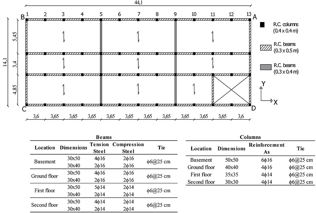
Figure 2. Main geometrical and structural properties of the first level of the case study building.
“The structure is made of RC frames; in particular, there are 4 longitudinal frames (X direction), each with 12 equal bays of 4.70 m in span, and 4 transversal frames (Y direction) with 3 unequal bays of 5.40 m, 3.40 m and 4.80 m. RC frame members consist of 50-cm-square columns at the semibasement, 40 and 35 cm-square columns at the ground floor and other floors, respectively. In the longitudinal direction (X), 30 × 50-cm beams were designed only for gravity loads, while along the transversal direction (Y direction), they have dimensions 30 cm x 35 cm at the second floor and 30 x 40 cm at the other floors, with the exception of the two extreme beams, whose cross-section dimensions are 30 cm x 50 cm at all levels”(De Angelis and Pecce, 2020). The floors are made with cast-in-place RC joists alternate by hallow clay blocks with a lightening function, covered by a RC plate of 4 cm, for a total height of 22.
The staircase, characterized by knee-type beams with dimension 0.30 × 0.50 m, is placed in an asymmetric position.
An extensive in situ inspection campaign was carried out to identify the structural details of the members, such as longitudinal and transverse reinforcements since the original design was not available. The information of reinforcement details was integrated with a simulated design carried out by taking into account gravity loads only according to the criteria of the Royal Decree n. 2239 of 1939 that regulated the design of RC buildings up to 1971 in Italy.
The mechanical properties of the materials were obtained from non-destructive and laboratory tests on specimens pulled out from the structural elements according to Eurocode 8 (EN 1998, 2005) provisions. In particular, seven destructive (drilled cores) and 28 non-destructive tests (rebound hammer and ultrasonic pulse velocity test) were performed on the most significant structural elements. A single homogeneous concrete class, characterized by an average cylinder compressive strength equal to 15.4 MPa was obtained from the correlation procedure involving the use of rebound hammer index, ultrasonic pulse velocity and compressive core strength. Tensile tests on the steel bars extracted (smooth mild steel) provided a mean yielding strength value of 299 MPa.
The geometrical survey together with the in situ inspections and the non-destructive tests carried out enabled to achieve a Knowledge Level 1.
The infill walls and partitions were grouped into categories according to the result of a preliminary thermographic study to limit the number of essays (holes extended for the entire thickness) and endoscopic tests (Figure 3). Six different typologies of walls (external and internal walls) were identified in the structure that are hollow clay brick infill walls (Type 1, Type 5, and Type 6), double-leaf infill walls (Type 2, Type 4), and solid block infill walls (Type 3). It is worth to note that all the typologies of infill walls detected in the building are characterized by horizontal mortar joints of ~1–1.5 cm thickness, while the vertical layers are offset. The hollow clay bricks are arranged with horizontal holes, and they are characterized by a void percentage approximately of 55%. A sketch of the different infill walls and partition typology is presented in Figure 4 together with their percentage in the building. A detailed description of the stratigraphy of the thickness is reported in Table 1.
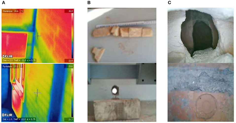
Figure 3. Infill wall identification: (A) Thermographic test, (B) essay, (C) endoscopic test.

Figure 4. External and internal infill wall typology (A) and distribution in the model (B).
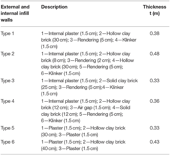
Table 1. Typologies of infill walls and partition.
The selected case study was tested through AVT (ambient vibration test), and the calibration of the linear model was addressed to establish the role of the infill walls in the dynamic response in terms of stiffness. The details of the in situ dynamic test are reported in De Angelis and Pecce, 2019.
The first mode detected was translational in the transversal direction with a frequency of 3.19 Hz; the second and third mode, instead, were roto-translational with a frequency of 3.89 and 4.16 Hz, respectively.
The model shown in Figure 4 was developed using SAP2000 software (Computers Structures Inc, 2016) including the RC elements (columns, beams, and walls), the floors, the infill walls, and the internal partitions. The columns and beams were modeled using frame elements, while the floor and RC walls were modeled using shell elements. The model takes into account the flexibility of the floor through the calibration of the shells' thickness. The effect of the external and internal masonry infills on the overall response of the structures was implemented using shell elements and rigid connections between the walls and the main structure. The additional stiffness offered by the staircase was taken into account in the model introducing the knee-type beams modeled as elastic frame elements. The foundation was excluded from the model, therefore the vertical structural elements (columns and walls) were fully restrained at the base.
More details about the experimental dynamic results are available in De Angelis (2017).
The FE model introduced in the previous section is used to investigate the effect of the internal partitions and exterior infill walls on the flexibility of the floor and the dynamic properties of the building. To underline the role of the infill walls, the main dynamic properties of the building modeled as bare and infilled frame are compared. In Table 2, the frequencies and modal mass ratios for the two models are shown. In order to compare the mode shapes of the bare and infilled models, the displacement at two opposite corners (A and C) of the building at each one of the four stories are considered for the X and Y directions. The results for each mode along the height of the building are normalized with respect to the maximum displacement among the ones attained in the two corners in both directions X and Y; therefore, the maximum value “1” is reached at only one floor, in one of the two corners for one of the two directions X and Y. The normalized results are depicted in Figure 5 for the first five modes.
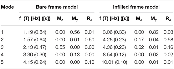
Table 2. Frequencies and percentage of participation masses for bare and infilled frame.
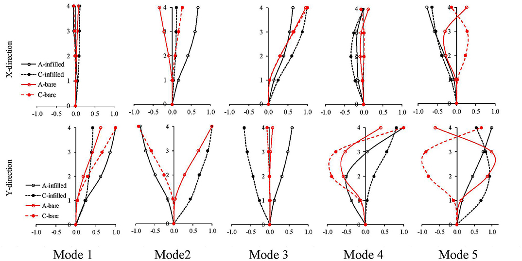
Figure 5. Mode shapes obtained from the infilled (black line) and bare (red line) frame models.
The first and third modes of the bare frame model (red line in Figure 5) are essentially translational such as the mode shapes for both corners are similar involving deformations mainly in the Y and X directions, respectively. The third mode has components in both X and Y directions, and the mode-shape components in the same direction have opposite signs at the two corners indicating that it is a torsional mode. The last two modes (fourth and fifth) are, respectively, the second translational mode in the Y direction and the second torsional mode. By introducing the infill walls in the model, the mode shape changes. The first mode is still translational in the Y direction, but the same-direction components at the two corners have different magnitudes showing that there is a torsional effect. The second and third modes can be defined roto-translational; in fact, they are basically torsional modes with significant components in the X direction. It is worth to note that the coupling effect between torsional and translational modes can be related to the presence and type of external infill walls. In fact, the second mode shape of the bare frame, comprehensive of the knee beam of the staircase, gives opposite displacements at the opposite corners along the X direction (Figure 5 second top graph) showing a pure torsional mode, while for the infilled frame, the displacements have the same sign emphasizing the coupling effect.
In retrofitting schemes or in new building designs, engineers often assume the hypothesis of rigid floors in their plane. Moreover, this assumption can simplify the model formulation since it leads to a reduction of the degrees of freedom and ensures efficient computations but it is not always true.
The designer of RC buildings could adopt technological rules as that one suggested by Eurocode 2 realizing the top concrete slab more than 4 cm high to assume an in-plane rigid behavior of the floor. However, in the case of existing buildings, these details are quite always disregarded due to aged code provisions and old types of RC floors. Therefore, it is important to know if the floor and roof diaphragms can be defined as rigid or flexible.
The international codes suggest either quantitative or qualitative criteria to define the rigidity of a floor. For example, (ASCE 7-05, 2002) allows a building designer to qualitatively idealize a concrete diaphragm as rigid solely based on the diaphragm's aspect ratio. It states “Diaphragms of concrete slabs or concrete filled metal deck with span to dept ratios of 3 or less in structures that have no horizontal irregularities are permitted to be idealized as rigid” (ASCE 7-05, 2002). A quantitative criterion is also given through the factor β, reported in equation 1, defined as the ratio of the maximum displacement of the vertical elements in the plane of the floor (Δflex) to the average story displacement of the associated story (Δstorey).
Thus, the floor can be classified as rigid if β < 2.
Instead (FEMA P750, 2009) provides a quantitative criterion, which defines floor as either flexible, stiff, or rigid based on a factor λ, reported in Equation 2.
If λ is larger than 2, the floor is deformable, while if λ is lower than 0.5, the floor is rigid. If λ is included between 0.5 and 2, the floor is “stiff” (neither flexible nor rigid).
According to (EN 1998, 2005), a rigorous verification of diaphragm rigidity requires FE modeling using two-dimensional finite elements; in fact, it is stated that, “The diaphragm is taken as been rigid, if, when it is modeled with its actual in-plane flexibility, its horizontal displacements nowhere exceed those resulting from the rigid diaphragm assumption by more than 10% of the corresponding absolute horizontal displacement in the seismic design situation”( EN 1998, 2005).
The efficiency as well as the accuracy of the available indications in codes and standards were analyzed by several researchers (Doudoumis and Athanatopoulou, 2001; Moeni and Rafezy, 2011; Koliou et al., 2015).
Anyway it is clear that the flexibility of the floor is a relative property influenced by the ratio between the in-plane stiffness of the floor with respect to the lateral stiffness of the resistant elements. In particular, Tena-Colunga et al. (2015) investigated the effects of different floor typologies and thicknesses on several buildings. Instead, Pecce et al. (2017) analyzed the influence of the lightening elements in RC floors on the in-plane floor deformability. However, the flexibility of the floors is typical in shear wall buildings (Kunnath et al., 1991; Saffarini and Qudaimat, 1992; Ahmadi et al., 2014; Pecce et al., 2019); therefore, the influence of the infill walls on the floor response is an interesting topic that is little studied.
Other authors, such as Fleischman and Farrow (2001), Lee and Kuchma (2008), and Sadashiva et al. (2011), evaluated the influence of the floor flexibility on the vibration periods of structures underlining the well-known “modal shifting,” i.e., the inversion of the modes toward the configuration with rigid diaphragm. Furthermore, Sivori et al. (2019) developed a tool to validate the assumption of in-plane rigid behavior of diaphragms using vibration data, opening the way to the identification of the floor flexibility through the dynamic response of the building.
Based on the information provided by scientific literature, it is well-known that the evaluation of the floor flexibility as well as its effect on the structural behavior of RC buildings should take into account many aspects, i.e., the shape ratio, the in-plane irregularities, and the position and relative stiffness of the vertical elements.
A possible way to estimate the real effect of the floor flexibility is to calculate the horizontal displacement under seismic loads, as suggested by codes, but it is more interesting to explore the possibility of focusing this aspect through the vibration modes, that is, a perspective of using dynamic tests in situ for defining this property of the existing buildings.
Thus, the main scope of this section is to evaluate the deformability of the floor from the mode shapes.
In particular, two types of models were developed to account for different in-plane stiffness of the diaphragms:
▪ The rigid-diaphragm model called “Model R” with a rigid diaphragm behavior;
▪ The flexible-diaphragm model called “Model F” in which the floor diaphragms are modeled with four-node shell elements. Models with different thicknesses of the floor are considered.
The modal properties, i.e., the frequencies (f), periods (T), modal mass ratios (M), and mode shapes, obtained by solving an eigenvalues analysis, are reported in Table 3; the mass of the floor is assumed constant for excluding this variable from the analyses.
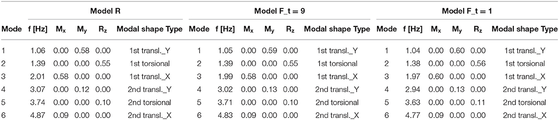
Table 3. Modal properties of the models with different in-plane stiffness of the diaphragm.
As shown in Table 3, for a bare frame building, the different in-plane stiffnesses of the diaphragms has a low influence on the frequencies and modal mass ratios; really, the floor can be considered always rigid in framed structures as is well-known (Pecce et al., 2017). In fact, removing the hypothesis of rigid diaphragm and modeling the floors as shell elements with a finite stiffness, there is a negligible variation, <2 and 5% in the case of slab with equivalent thickness (t) equal to 9 and 1 cm, respectively.
The mode shape along the long side of the floor is drawn considering the displacement at each column, whose progressive numeration is reported in Figure 2.
The resulting mode shapes for the roof at the first and second translational mode in the Y direction and at the first and second torsional modes are depicted in Figure 6.
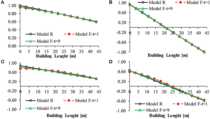
Figure 6. Mode shapes for the roof diaphragm: (A) first translational Y; (B) first torsional; (C) second translational Y; (D) second torsional.
As shown in Figure 6, the response of the diaphragm (Model R) is a line, but in case of the bare frame, it remains a line also for very thin thickness of the floor. Therefore, the hypothesis of the rigidity of the floor can be applied simplifying the model and reducing the computational effort.
The calibrated infilled model in which the infill walls are modeled through shell elements is used to evaluate the in-plane floor flexibility. To this scope, the rigid-diaphragm model (Model R) and the flexible-diaphragm model (Model F), as for the bare frame, are considered.
In Table 4, the frequencies and the modal mass ratio for each mode shape detected are reported.
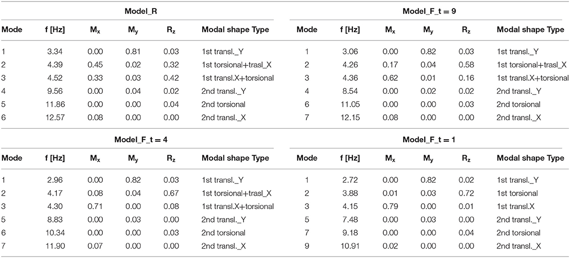
Table 4. Modal properties of the infilled models with different in-plane stiffness of the diaphragm.
In this case, it is worth to underline how unlike the case of the bare frame, the modeling of the floor with its finite stiffness has a greater influence on the frequency values that undergo significant reductions of about 6, 8, and 16% passing from an equivalent thickness equal to 9, 4, and 1 cm, respectively.
As regard the modal mass ratios, the contribution of the in-plane stiffness of the floor is even more significant, and in particular, it leads to a reduction of the coupling between torsional and translation modes; in the case of a rigid floor, the second global mode of the structure is characterized by a modal mass ratio of 32% around the Z-direction and 45% in the X-direction; instead, when the floor is modeled with its stiffness, the coupling term in the X direction for the same mode is reduced to 17 and 8% in the case of equivalent thicknesses of 9 and 4 cm, respectively.
Moreover, a further reduction in the equivalent thickness of the floor equal to 1 cm (in this case, the floor is definitely flexible) makes the second global mode purely torsional. Therefore, the modeling of the actual in-plane stiffness of the floor leads to a regularization of the modes.
To understand if the floor can be considered rigid or flexible, the mode shapes along the length of the roof are mapped in Figure 7 for the first translational mode in the Y direction (Mode 1), the first coupled torsional + translational Y mode (Mode 2), the second translational mode in the Y direction (Mode 4), and the second torsional mode (Mode 5).
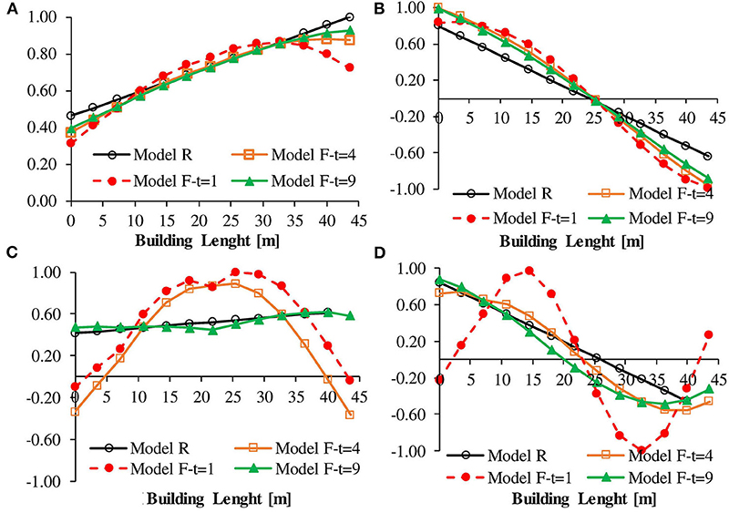
Figure 7. Mode shapes for the roof diaphragm (infilled frame): (A) first translational Y; (B) first torsional; (C) second translational Y; (D) second torsional.
In the case of infilled frame building, unlike what happened for the bare frame building, the flexibility of the floor gives always an effect with respect to the model with the rigid floor. The effect is more evident for the higher translational mode along Y and rotational modes (modes 4 and 5, respectively), especially when the floor thickness is reduced from 9 to 4 cm.
Therefore, two remarks can be evidenced; it is possible to estimate if the floor has a significant flexibility by a dynamic identification in situ through the higher-mode analysis; furthermore, for the infilled frames, the flexibility of the floor could be important to be introduced in the modeling for the seismic analysis.
In order to assess the seismic response of the building, the effect of infill walls has been investigated using a linear dynamic analysis. This method of analysis is based on the modal response spectrum that permits to consider the contribution of fundamental and higher modes to the dynamic behavior of the structures.
In the model, the floor diaphragms are introduced as shell elements with four nodes to take into account the real flexibility. However, it is worth noticing that the contribution of the infill walls to the seismic performance requires a high stiffness of the floor that, in this case study, is quite assured by the concrete slab; conversely, if the infilled building has a deformable floor, an intervention for improving the stiffness of the floor has to be designed, as adding thickness to the concrete slab. The seismic action is evaluated by the elastic response spectra provided by the Italian code, for a returned period TR = 712 years and soil type C. The well-known parameters used for the determination of the elastic acceleration spectrum are the following:
▪ Hazard parameters: ag = 0.308 g – F0 = 2.32;
▪ Soil parameters: SS = 1.273–CC = 1.444 – ST = 1.00 – S = 1.273;
▪ Significant points of the spectrum: = 0.381 – TB = 0.183 s – TC = 0.550 s – TD = 2.833 s
The seismic input was obtained from the horizontal acceleration spectrum, neglecting the vertical component; the seismic action was applied combining it along the two main directions (100% in one direction and 30% in the orthogonal one).
Therefore, the seismic assessment was carried out for both the bare and infilled models described in the previous sections assuming the behavior factor q = 1.5, which means neglecting the ductility resources of the structure designed without the seismic details. However, the infilled model is modified in order to tailor a strengthening intervention considering the infill walls as isolated masonry walls that collaborate with the RC frame. The walls are separated by the RC columns to avoid the local stresses in the RC members and the failure of the walls as struts constrained by the corner of the frame. The cut has a thickness of 5–10 cm that can be filled by a deformable material for the thermal insulation; furthermore, the gap between the columns and the walls allow to realize also a strengthening of the columns, if it is necessary, like a confinement by composite materials. The linear dynamic behavior of the building remains quite the same in terms of vibration periods (i.e., the periods increase of ~3%) and modal shapes; therefore, the discussion presented in the previous sections is still valid with and without the separation of the walls from the columns. Conversely, the non-linear response and the failure mode change and the linear analysis using the model with shell elements for the walls are reliable for the seismic analysis.
The bare model and the infilled model with the gap between the columns and infills are characterized by a fundamental period equal to 0.84 and 0.34 s, respectively. The period of the bare frame model is in the range of the descending branch of the spectrum; therefore, spectral acceleration increases of 55% are due to the interaction of the infill walls. Nevertheless, the contribution of the infill wall stiffness reduces the vibration period of the structure enhancing the spectral seismic acceleration; the contribution of the infill walls resistance gives a higher increase in the capacity of the structure. In order to have a global parameter for evaluating the effect of the infill walls, the peak ground acceleration capacity (PGAC) is evaluated as the PGA that gives all the elements verified at the LSLS, without and with the infill walls, and divided by the PGA demand (PGAD). The ratio PGAC/PGAD increase from 0.22 to 0.45 underlying the benefit of the infill wall collaboration.
As an example, in Figure 8, the trends of shear and bending moment stresses for a typical beam of the building are reported.
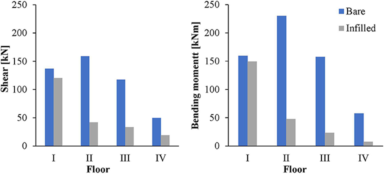
Figure 8. Shear and bending moment stresses for a typical beam.
In order to assess the seismic vulnerability of the building, the results of the linear dynamic analysis are compared in terms of capacity/demand ratio (CDR) in shear and bending of the columns and beams, as reported in Table 5. The capacity of the members is evaluated according the provisions of Eurocode 2 at the ultimate limit state.
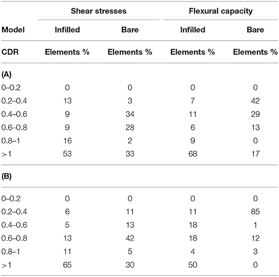
Table 5. Capacity/demand ratio of shear stress and flexural capacity of beams (A) and columns (B).
In most of the cases, the CDR of the beams and columns of the buildings is lower than 1, pointing out the inadequate safety of the existing building and the necessity of retrofitting. As can be seen from the distribution of CDR ratios, the bare model is strongly deficient, while the main deficiency of the infilled model is related to the columns of the external frames of the basement. In fact at this level, squat portions of the columns are defined by the masonry walls that do not extend throughout the height of the columns due to the openings; therefore, a shear mechanism can occur. The minimum CDR of the masonry panels is 0.51, but the mean value is 0.88. The shear and flexural strength of the masonry walls are evaluated according to the provisions of the Italian Building Code (D.M.17/01/2018) that are the same as the Eurocode 8 (EN 1998, 2005). In particular, the capacity in shear is evaluated as:
Vt is the strength corresponding to the sliding cracking of the panel, and it is calculated as
where:
- l is the width of the panel;
- t is the thickness of the panel;
- b is a coefficient related to the panel slenderness, and it is assumed equal to 1.5;
- τ0d is the masonry reference shear strength, obtained from the average masonry shear strength τ0 by means of the relation τ0d = τ0/γm · FC, where γm = 2 is the partial safety factor of the masonry, and FC is the so-called confidence factor assumed equal to 1 for the knowledge level 3 in this case;
- σ0 is the average vertical compressive stress, defined as σ0 = N/ l · t, where N is the normal action on the beam.
Instead, Vs, the strength corresponding to the diagonal cracking, is calculated as:
where:
- l′ is the length of the compressed zone;
- fvd = (τ0 + 0.4σn)/γm · FC is the design masonry shear strength with σn the average compressive stress action on l′ (i.e., σn = N/l' · t).
Instead, the capacity in the bending moment for rocking failure can be evaluated as:
where fd = fm/ γm · FC, with fm being the masonry average compressive strength.
In this case, a compressive strength equal to 2 and 4 MPa are adopted for the hollow clay brick masonry and solid clay brick masonry, respectively.
In case of double leaves infill walls, the in-plane resistance of the panel is evaluated as the sum of the two contributions.
Since the presence of the infill walls plays a significant role, the proposed retrofitting solution is mainly devoted to the strengthening of infill panels for their effective integration in the superstructure-like masonry walls. It was shown by several researchers (Kakaletsis et al., 2011; Antonopoulos and Anagnostopoulos, 2012; Porco et al., 2015) that it is an optimal approach for exploiting additional strength resources of the building and improving its seismic response.
Herein, a more general retrofitting solution is proposed, and it includes the following interventions:
(a) strengthening of the existing infill panels, already separated by the columns by a cut of 5–10 cm thickness filled by material for thermal insulation with a very low elastic modulus (10 MPa), using the FRCM (fabric-reinforced cementitious matrix) technique according to the suggestions of the specific guideline (CNR-DT 215/2018, 2018). The FRCM with fiber glass meshes and mortar are selected and applied on both sides of the infill walls extending also on the RC elements. A reliable collaboration of the masonry and the strengthening system is assured in the plane of the wall by fiber spikes that connect the two FRCM thickness on masonry and RC components improving the in-plane stiffness and strength. Furthermore, the connection of the FRCM on the RC columns and beams assures a constraint of the wall to avoid the out-of-plane overturning.
In order to account for the FRCM strengthening, increasing the resistance of the masonry infill walls by a factor of 1.3, according to the provisions of the Italian code (D.M.17/01/2018). The effectiveness of this amplification factor of the in-plane capacity of masonry infills made with hollow clay brick applying FRCM is supported by recent experimental results (Koutas et al., 2014; Almeida et al., 2015; Giaretton et al., 2018).
Further interventions are introduced to improve the seismic response of the building:
(b) removal of internal masonry infill partitions and replacement with drywall partitions that have no contribution to the in-plane stiffness of the building; a regularization of the dynamic response is obtained: in fact, the second and third modes that can be defined as roto-translational with a significant coupling term become purely translational in the X direction and torsional with a reduced coupling term, respectively;
(c) addition of new walls along the longitudinal direction of the building, as shown in Figure 9.
(d) extension of the existing RC walls at the basement reducing the row window for avoiding the short-column mechanism.
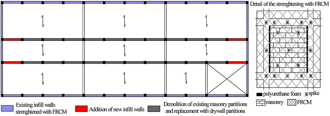
Figure 9. Proposed retrofitting solution.
In Table 6, the percentage of beams and columns characterized by different values of CDR ratios for shear stresses and flexural capacity are reported, evidencing the increment of the RC element percentage that are verified after the intervention in a range of 15–35% (comparison with Table 5).
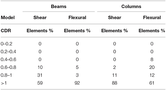
Table 6. Capacity/demand ratio of shear stress and flexural capacity of beams and columns after the retrofitting intervention.
The evaluation of the benefit arisen with the intervention by a global parameter PGAC/PGAD points out an increment from 0.45 to 0.61 evidencing the opportunity of using infill walls for the seismic upgrade of infilled RC frame buildings within a global intervention that considers further details specific of the singular building.
Finally, it is worth noticing that only the increment of strength has been considered in the evaluation of the performance after the intervention; however, it is clear that an increment of ductility can be considered, too. In fact, the isolated walls strengthened by FRCM allow to increase the behavior factor from 1.5 to 2 (that is applied at least to masonry buildings). Furthermore, by adding a confinement of the columns, this factor can be assumed also for the entire structure enhancing the PGAC/PGAD ratio to ~0.8. Obviously the PGAC/PGAD ratio could be obtained by a more refined design process of the intervention but this is out of the scope of the paper that is aimed to evaluate the possible contribution of the infill walls.
The existing building proposed as case study was selected because it has a typical RC frame structure designed only for gravitational loads, and it is widespread in Italy. Furthermore, the building has been already tested through AVT verifying a strong influence of the infill walls on the seismic response. In this work, the model calibrated by the experimental results is used for studying the effect of the infill walls on the flexibility of the floor diaphragm, evaluating the seismic performance of the building by a linear dynamic analysis, with and without the introduction of the infill walls. Moreover, an upgrading intervention using the contribution of the masonry panels and re-designing the internal partitions is proposed.
The following results of the analyses can be considered reliable for typical existing RC frame buildings realized with infill walls made with hollow clay blocks:
- The floor flexibility under seismic actions can be modified by the interaction between the frame structure and the masonry panels because it is a relative property depending on the ratio between the stiffness of the vertical resistant elements and the in-plane stiffness of the floor. The possibility of estimating the flexibility of the floor by means of the dynamic response of the structure (vibration tests in situ or an adequate numerical modeling) is particularly interesting but considering the higher modes of the modal analysis. This result is surely more consolidated in the field of masonry buildings or in case of clearly flexible floors as wood ones, but is not usually considered in RC frame structures because it is well-known that for bare frames the floor is always rigid. Thus, the introduction of the infill walls in the model assumes an important role also for this feature and could require the modeling of the floor for the seismic analysis;
- The linear elastic analyses with response to spectrum and behavior factor q = 1.5 for assessing the impact of the infill panels on the seismic performance of the structure evidenced their important role in enhancing the spectrum acceleration due the higher stiffness of the infilled structure;
- Nevertheless, the contribution of the infill wall stiffness reduces the vibration period of the structure, enhancing the spectral seismic acceleration; the contribution of the infill wall resistance gives a higher increase in the capacity of the structure. The ratio PGAC/PGAD increases from 0.22 to 0.45 underlying the benefit of the infill wall collaboration.
- The infill walls can be used in an upgrade intervention with the innovative technique of FRCM increasing the resistance of the masonry panels separated from the RC columns by a cut. The intervention can be convenient because the variation of the building stiffness is negligible with respect to the resistance increment. Furthermore, the connection of the FRCM to the beams and columns avoid the out-of-plane overturning or the infill walls. Clearly, the intervention has to be tailored on the specific case and can be comprehensive of a reviewing of further details especially for reducing the structural irregularities or local details. In this case, the accurate numerical model evidenced a not negligible effect of the irregular distribution of the internal partitions; therefore, most of them have been replaced with more flexible ones, and a regular disposition of masonry partitions has been proposed to contribute to the seismic performance. The ratio PGAC/PGAD increases from 0.45 to 0.61 pointing out the benefit of the intervention that could magnify to 0.8 taking into account an improvement in the ductility through a behavior factor q = 2.
The analyses proposed in the paper highlight the features of the numerical models that are necessary for a reliable evaluation of the seismic response of RC infilled frame buildings and suggest the approach that can be applied to design a seismic upgrade intervention using the contribution of the infill walls, with a relevant benefit. Nevertheless, the numerical results are specific of the case study; many typical aspects have been evidenced, and further analyses are in progress in improving the generalization of the results.
The raw data supporting the conclusions of this article will be made available by the authors, without undue reservation.
MP conceived the research idea and gave advice on the retrofit strategy. AD collected scientific articles for state of the art, performed the analyses, analyzed the results, and wrote the paper. Both authors revised the paper for overall consistency and scopes.
DPC RELUIS 2019-2021- WP5-Task 5.1 is gratefully acknowledged for funding the research activity.
The authors declare that the research was conducted in the absence of any commercial or financial relationships that could be construed as a potential conflict of interest.
Ahmadi, M., Bakar, S. A., and Abbas, H. S. (2014). Investigation into diaphragm flexibility using shear wall. J. Croatian Assoc. Civil Eng. 66, 831–836. doi: 10.14256/JCE.1049.2014
Almeida, J. A., Pereira, E. B., and Barros, J. A. (2015). Assessment of overlay masonry strengthening system under in-plane monotonic and cyclic loading using the diagonal tensile test. Constr. Build. Mater. 94, 851–865. doi: 10.1016/j.conbuildmat.2015.07.040
Antonopoulos, T. A., and Anagnostopoulos, S. A. (2012). Seismic evaluation and upgrading of RC buildings with weak open ground stories. J. Earthq. Struct. 3, 611–628. doi: 10.12989/eas.2012.3.3_4.611
Binici, B., Ozcebe, G., and Ozcelik, R. (2007). Analysis and design of FRP composites for seismic retrofit of infill walls in reinforced concrete frames. Composites B Eng. 38, 575–583. doi: 10.1016/j.compositesb.2006.08.007
Celarec, D., Ricci, P., and Dolsek, M. (2012). The sensitivity of seismic response parameters of the uncertain modeling variables of masonry-infilled reinforced concrete frames. Eng. Struct. 35, 165–177. doi: 10.1016/j.engstruct.2011.11.007
Celik, O. C. (2015). Effect of AAC infill walls on structural system dynamics of a concrete building. J. Earthq. Eng. 20, 738–748. doi: 10.1080/13632469.2015.1104757
Chaker, A. A., and Cherifati, A. (1999). Influence of masonry infill panels on the vibration and stiffness characteristics of R/C frame buildings. Earthq. Eng. Struct. Dyn. 28, 1061–1065. doi: 10.1002/(SICI)1096-9845(199909)28:9<1061::AID-EQE856>3.0.CO;2-3
CNR-DT 215/2018 (2018). Guide for the Design and Construction of Externally Bonded Fibre Reinforced Inorganic Matrix Systems for Strengthening Existing Structures. Rome: National Research Council.
Computers and Structures Inc. (2016). SAP 2000: Linear and Nonlinear Static and Dynamic Analysis of Three-Dimensional Structures. Berkeley: Computers and Structures, Inc.
Crisafulli, F. J. (1997). Seismic behaviour of reinforced concrete structures with masonry infills. (Ph.D. thesis): University of Canterbury, Christchurch.
D.M.17/01/2018. Aggiornamento delle Norme Tecniche per le Costruzioni (NTC). Gazzetta Ufficiale n.42. Rome: Ministero Delle Infrastrutturee Dei Trasporti.
De Angelis, A. (2017). Nonstructural components seismic response: The out-of-plane behavior of infill walls(PhD Thesis). Benevento, Italy.
De Angelis, A., and Pecce, M. R. (2018). Out-of-plane structural identification of a masonry infill wall inside beam-column RC frames. Eng. Struct. 173, 546–558. doi: 10.1016/j.engstruct.2018.06.072
De Angelis, A., and Pecce, M. R. (2019). The structural identification of the infill walls contribution in the dynamic response of framed buildings. Struct. Control Health Monitor. 26:e2405. doi: 10.1002/stc.2405
De Angelis, A., and Pecce, M. R. (2020). “The effect of infill walls on the structural identification of an existing rc frame building,” in Proceedings of Italian Concrete Days 2018. ICD 2018. Lecture Notes in Civil Engineering, Vol. 42, eds. M. di Prisco and M. Menegotto (Cham: Springer). p. 56–68. doi: 10.1007/978-3-030-23748-6_5
De Risi, M.T., Furtado, A., Rodrigues, H., Melo, J., Verderame, G.M., António, A., et al. (2020). Experimental analysis of strengthening solutions for the out-of-plane collapse of masonry infills in RC structures through textile reinforced mortars. Eng. Struct. 207:110203. doi: 10.1016/j.engstruct.2020.110203
Decree, Regio 16/11/1939 n. 2229 (1939). Norme per la esecuzione delle opere in conglomerato cementizio semplice od armato. Rome: Italian Government.
Dolsek, M., and Fajfa, P. (2001). Soft storey effects in uniformly infilled reinforced concrete frames. J. Earthq. Eng. 5, 1–12. doi: 10.1080/13632460109350383
Doudoumis, I. N., and Athanatopoulou, A. M. (2001). Code provisions and analytical modelling for the in-plane flexibility of floor diaphragms in building structures. J. Earthq. Eng. 5, 565–594. doi: 10.1080/13632460109350406
Dymiotis, C., Kappos, A. J., and Chryssanthopoulos, M. K. (2001). Seismic reliability of masonry infilled RC frames. J. Earthq. Eng. 127, 296–305. doi: 10.1061/(ASCE)0733-9445(2001)127:3(296)
EN 1998-3:2005. (2005). Eurocode 8: Design of Structures for Earthquake Resistance - Part 3: Assessment and Retrofit of Buildings. Brussels: European Committee for Standardization (CEN).
Fardis, M. N., and Panagiotakos, T. B. (1997). Seismic design and response of bare and masonry-infilled reinforced concrete buildings. Part II: infilled structures. J. Earthq. Eng. 1, 475–503. doi: 10.1080/13632469708962375
FEMA P750 (2009). National Earthquake Hazard Reduction Program NEHRP- Recommended Seismic Provisions for New Buildings and Other Structures. Washington, DC: Federal Emergency Management Agency.
Fleischman, R. B., and Farrow, K. T. (2001). Dynamic behaviour of perimeter lateral-system structures with flexible diaphragms. Earthq. Eng. Struct. Dyn. 30, 745–763. doi: 10.1002/eqe.36
Furtado, A., Vila-Pouca, N., Varum, H., and Arêde, A. (2019). Study of the seismic response on the infill masonry walls of a 15-storey reinforced concrete structure in Nepal. Buildings 9:39. doi: 10.3390/buildings9020039
Giaretton, M., Dizhur, D., Garbin, E., Ingham, J. M., and da Porto, F. (2018). In-plane strengthening of clay brick and block masonry walls using textile-reinforced mortar. J. Compos. Constr. 22:04018028. doi: 10.1061/(ASCE)CC.1943-5614.0000866
Hans, S., Boutin, C., Ibrahim, E., and Roussillon, P. (2005). In situ experiments and seismic analysis of existing buildings. part I: experimental investigations. Earthq. Eng. Struct. Dyn. 34, 1513–1529. doi: 10.1002/eqe.502
Kakaletsis, D. J., David, K. N., and Karayannis, C. G. (2011). Effectiveness of some conventional seismic retrofitting techniques for bare and infilled R/C frames. Struct. Eng. Mech. 39, 499–520. doi: 10.12989/sem.2011.39.4.499
Koliou, M., Filiatrault, A., Kelly, D., and Lawson, J. (2015). Buildings with rigid walls and flexible roof diaphragms I: evaluation of current U.S. seismic provisions. J. Struct. Eng. 142:04015166. doi: 10.1061/(ASCE)ST.1943-541X.0001438
Koutas, L., Bousias, S. N., and Triantafillou, T. C. (2015). Seismic strengthening of masonry-infilled RC frames with TRM: experimental study. J. Comp. Constr. 19:04014048.
Koutas, L., Triantafillou, T. C., and Bousias, S. N. (2014). Analytical modeling of masonry-infilled RC frames retrofitted with textile-reinforced mortar. J. Compos. Constr. 19:04014082. doi: 10.1061/(ASCE)CC.1943-5614.0000553
Kunnath, S. K., Panahshahi, N., and Reinhorn, A. M. (1991). Seismic response of RC buildings with inelastic floor diaphragms. J. Struct. Eng. ASCE. 117, 1218–1237. doi: 10.1061/(ASCE)0733-9445(1991)117:4(1218)
Kyriakides, M. A., and Billington, S. L. (2013). Cyclic response of nonductile reinforced concrete frames with unreinforced masonry infills retrofitted with engineered cementitious composites. J. Struct. Eng. 140:04013046.
Lee, H. J., and Kuchma, D. A. (2008). Seismic response of parking structures with precast concrete diaphragms. PCI J. 53, 71–94. doi: 10.15554/pcij.03012008.71.94
Moeni, M., and Rafezy, B. (2011). Investigation into the floor diaphragms flexibility in reinforced concrete structures and code provision. Glob. J. Res. Eng. 11, 25–35
Pecce, M., Ceroni, F., Maddaloni, G. (2017). Assessment of the in-plane deformability of RC floors with traditional and innovative lightening elements in RC framed and wall structures. Bull. Earthq. Eng. 15, 3125–3149. doi: 10.1007/s10518-017-0083-0
Pecce, M., Ceroni, F., Maddaloni, G., (2019). In-plane deformability of RC floors: assessment of the main parameters and influence on dynamic behaviour. Bull. Earthq. Eng. 17, 297–311. doi: 10.1007/s10518-018-0432-7
Perrone, D., Leone, M., and Aiello, M. A. (2017). Non-linear behaviour of masonry infilled RC frames: Influence of masonry mechanical properties. Eng. Struct. 150, 875–891. doi: 10.1016/j.engstruct.2017.08.001
Porco, F., Fiore, A., Uva, G., and Raffaele, D. (2015). The influence of infilled panels in retrofitting interventions of existing reinforced concrete buildings: a case study. Struct. Infrastruct. Eng. 11, 162–175. doi: 10.1080/15732479.2013.862726
Ricci, P., De Luca, F., and Verderame, G. M. (2011). 6th April 2009 L'Aquila earthquake, Italy: reinforced concrete building performance. Bull. Earthq. Eng. 9, 285–305. doi: 10.1007/s10518-010-9204-8
Ricci, P., De Risi, M. T., Verderame, G. M., and Manfredi, G. (2013). Influence of infill distribution and design typology on seismic performance of low-and mid-rise RC buildings. Bull. Earthq. Eng. 11:1585. doi: 10.1007/s10518-013-9453-4
Rodrigues, H., Furtado, A., Vila-Pouca, N., Varum, H., and Barbosa, A. R. (2018). Seismic assessment of a school building in Nepal and analysis of retrofitting solutions. Int. J. Civ. Eng. 16, 1573–1589. doi: 10.1007/s40999-018-0297-9
Sadashiva, V. K., MacRae, G. A., and Deam, B. L. (2011). “A mechanics based approach to quantify diaphragm flexibility effects,” in Proceedings of 9th Pacific Conference on Earthquake Engineering (Auckland:CD ROM, Paper No 114).
Saffarini, H., and Qudaimat, M. (1992). In-plane floor deformations in RC structures. J. Struct. Eng. 118, 3089–3102. doi: 10.1061/(ASCE)0733-9445(1992)118:11(3089)
Sivori, D., Lepidi, M., and Cattari, S. (2019). Ambient vibration tools to validate the rigid diaphragm assumption in the seismic assessment of buildings. Earthq. Eng. Struct. Dyn. 49, 194–211. doi: 10.1002/eqe.3235
Sousa, L., and Monteiro, R. (2018). Seismic retrofit options for non-structural building partition walls: impact on loss estimation and cost-benefit analysis. Eng. Struct. 161, 8–27. doi: 10.1016/j.engstruct.2018.01.028
Tena-Colunga, A., Chinchilla-Portillo, K. L., Juarez-Luna, G. (2015). Assessment of the diaphragm condition for floor systems used in urban buildings. Eng. Struct. 93, 70–84. doi: 10.1016/j.engstruct.2015.03.025
Keywords: infill walls, flexible floor, seismic analysis, RC building, strengthening intervention
Citation: De Angelis A and Pecce MR (2020) The Role of Infill Walls in the Dynamic Behavior and Seismic Upgrade of a Reinforced Concrete Framed Building. Front. Built Environ. 6:590114. doi: 10.3389/fbuil.2020.590114
Received: 31 July 2020; Accepted: 22 October 2020;
Published: 03 December 2020.
Edited by:
Maria Teresa De Risi, University of Naples Federico II, ItalyReviewed by:
Davorin Penava, Josip Juraj Strossmayer University of Osijek, CroatiaCopyright © 2020 De Angelis and Pecce. This is an open-access article distributed under the terms of the Creative Commons Attribution License (CC BY). The use, distribution or reproduction in other forums is permitted, provided the original author(s) and the copyright owner(s) are credited and that the original publication in this journal is cited, in accordance with accepted academic practice. No use, distribution or reproduction is permitted which does not comply with these terms.
*Correspondence: Alessandra De Angelis, YWRlYW5nZWxpc0B1bmlzYW5uaW8uaXQ=
Disclaimer: All claims expressed in this article are solely those of the authors and do not necessarily represent those of their affiliated organizations, or those of the publisher, the editors and the reviewers. Any product that may be evaluated in this article or claim that may be made by its manufacturer is not guaranteed or endorsed by the publisher.
Research integrity at Frontiers
Learn more about the work of our research integrity team to safeguard the quality of each article we publish.