 Kenneth H. Stokoe II1*
 Farnyuh Menq
94% of researchers rate our articles as excellent or good
Learn more about the work of our research integrity team to safeguard the quality of each article we publish.
Find out more
ORIGINAL RESEARCH article
Front. Built Environ., 09 November 2020
Sec. Earthquake Engineering
Volume 6 - 2020 | https://doi.org/10.3389/fbuil.2020.575973
This article is part of the Research TopicNatural Hazards Engineering Research Infrastructure (NHERI) 2016-2020: Mitigating the Impact of Natural Hazards on Civil Infrastructure and CommunitiesView all 16 articles
The Natural Hazards Engineering Research Infrastructure (NHERI) experimental facility at the University of Texas (NHERI@UTexas) is funded by the National Science Foundation (NSF). NHERI@UTexas contributes unique, large-scale, hydraulically controllable mobile shakers and associated instrumentation to study and develop novel, in-situ testing methods that can be used to evaluate the needs of existing infrastructure as well as optimize the design of future infrastructure. The ability to test existing infrastructure under actual field conditions bridges the gap in the transformative tools needed for the next frontier of resilient and sustainable natural-hazards research. Further, these unique facilities are available to any NSF-funded research. The field shakers and support equipment are described. Examples of on-going and future projects in three key areas of investigation that NHERI@UTexas is targeting are presented. These examples includes: (1) performing more accurate 2D/3D subsurface geotechnical imaging up larger depths, (2) characterizing liquefaction resistance and non-linear dynamic behavior in situ soils, and (3) developing in-situ methods non-destructive soil-foundation-structure interaction (SFSI) studies.
The Natural Hazards Engineering Research Infrastructure (NHERI) Program is the United States National Science Foundation (NSF) program for the continued development and operation of a network of large-scale facilities used to support natural hazards engineering research. Originally established by NSF under the Network for Earthquake Engineering Simulation (NEES) in 2000, the large-scale facility at the University of Texas at Austin (UT), then named NEES@UTexas, was renamed NHERI@UTexas on January 1, 2016 under the NHERI program. A key feature of the NEES program, and now the NHERI program, is the nationally distributed shared use facilities to support natural hazards engineering research. Experimental and computational resources provided by these shared use, NSF-supported facilities, as well as data collected from associated research projects, are made available to the broader research community. From 2000 to 2014, NEES@UTexas supported 30 shared-use projects and more than 25 non-shared-used projects. NHERI@UTexas has continued this shared-use practice since 2016. Between 2016 and 2020, NHERI@UTexas supported 12 shared-use projects and more than 12 non-shared-used projects. Shared-use projects are research projects funded by the NSF. Any NSF support research projects can request to use NHERI@UTexas facility. Shared-use projects are typically led by researchers from other universities, sometimes in cooperation with researchers from UT. These research projects often involve developing new testing techniques for specific goals. From designing the field studies, developing and constructing sensors, conducting the field tests, to uploading and analyzing data, each project lasts about 1 to 3 years. Non-shared-use projects have not been supported by NSF and have typically been conducted by researchers at UT. These type of projects are often service oriented and often last about 6 months. In this article, the equipment capabilities at NHERI@UTexas are discussed, and key areas of investigation and example shared-use projects are presented. These examples showcase how NHERI@UTexas equipment contribute to advancements in various areas of research. More information about NHERI@UTexas and the NSF-supported NHERI program can be found at https://utexas.designsafe-ci.org/.
Natural Hazards Engineering Research Infrastructure experimental facility at the University of Texas provides unique large, mobile dynamic shakers and associated instrumentation for in-situ testing of civil infrastructure. These innovative field testing methods can be used to evaluate behavior of existing infrastructure and to enhance the design of future infrastructure, which will contribute to the development of more resilient communities. While laboratory shake table at both small and large scales provide valuable insights into dynamic infrastructure behavior, focusing on these methodologies exclusively, without the ability to test real structural and geotechnical systems under actual field conditions, would leave a significant gap in the transformative tools needed for the next frontier of natural hazards research.
The equipment available at the NHERI@UTexas experimental facility includes: (1) five large, hydraulically controlled shakers mounted on mobile platforms (i.e., trucks) that can provide wide-band dynamic excitation sources for geotechnical and structural systems, (2) a tractor-trailer necessary to transport the four largest shakers, (3) a field supply truck with resources for mobile shaker maintenance and refueling in the field, (4) an instrumentation van that houses data acquisition systems and power generators, (5) an air-conditioned instrumentation trailer that serves as a work space in the field, and (6) collection wide array of field instrumentation, data acquisition systems, and various sensors for measuring vibrational motions and pore water pressures (Stokoe et al., 2017).
The five mobile shakers, shown in Figure 1 and summarized in Table 1, are named (1) T-Rex, (2) Liquidator, (3) Raptor, (4) Rattler, and (5) Thumper, The force and frequency generation capabilities of these shakers are shown in Figure 2. The two heaviest shakers are T-Rex (29,000 kg) and Liquidator (32,800 kg). T-Rex (Figure 1a) can generate large dynamic forces in any of three directions (vertical, horizontal in-line, and horizontal cross-line), where the shaking direction can be changed with a simple push of a button by the operator. The shaking system, mounted on an off-road, all-wheel-drive vehicle, can produce a maximum force output of around 267 kN in the vertical direction, and around 134 kN in each horizontal direction, as shown in Figures 2A,B, respectively. In addition to T-Rex’s shaking capabilities, it can also: (1) push cone penetrometers and other custom-made vibration and/or pressure-sensing instrumentation into the ground using a hydraulic ram located on the rear bumper of the vehicle (shown in Figure 3d), and (2) perform pull-over tests of large-scale structural models in the field using a hydraulically operated winch on the front bumper of the vehicle. In total, T-Rex’s capabilities make it unique in the world. Liquidator (Figure 1b) is a unique, custom-built shaker designed specifically for low-frequency, large-motion operation. To change the shaking direction from the vertical mode to the cross-line horizontal (shear) mode requires approximately two working days at the manufacturer’s facilities in Tulsa, OK. The shaker can generate a maximum force output of approximately 89 kN in either mode down to a frequency of 1.3 Hz, as shown in Figure 2. However, a modified configuration where the entire off-road mobile platform is lifted off the ground and oscillates in the vertical mode allows Liquidator to generate maximum forces of 89 kN down to a frequency of 0.7 Hz. Below 0.7 Hz, the force level decreases but is still substantial to about 0.3 Hz. This modification provides unique capabilities that can facilitate deeper (1 km or more) active-source subsurface imaging (Stokoe et al., 2019). Like T-Rex, the Liquidator shaking system is also housed on an off-road vehicle with hydraulic penetrometer/instrumentation pushing capabilities mounted on the rear steel bumper of the vehicle and a wench with pull-over capabilities mounted on the front steel bumper. Use of these pull-over capacities are illustrated in field studies with 1/4-scale bridge bents by Stokoe et al. (2017).
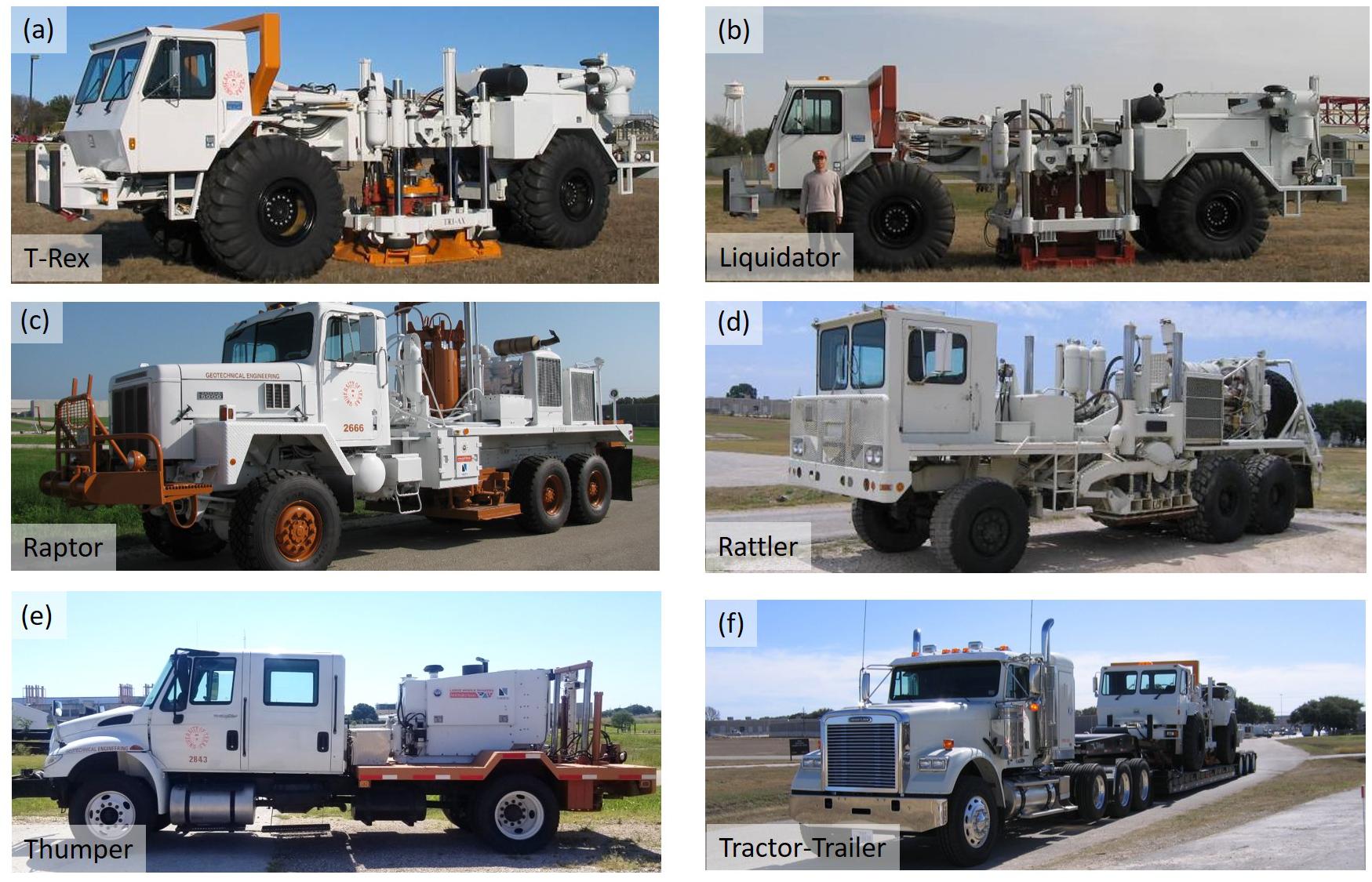
Figure 1. Photographs of the five mobile shakers and tractor-trailer rig available at NHERI@UTexas: (a) High-force, three-axis shaker called T-Rex, (b) Low-frequency, two-axis shaker called Liquidator, (c) Single-axis, vertical shaker called Raptor, (d) Single-axis, horizontal shaker called Rattler, (e) Urban, three-axis shaker called Thumper, and (f) Tractor-trailer rig, called the Big Rig, with T-Rex (after Stokoe et al., 2017).
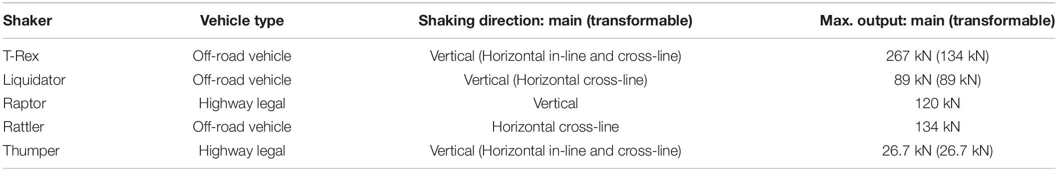
Table 1. Key features of these five shakers available at NHERI@UTexas.
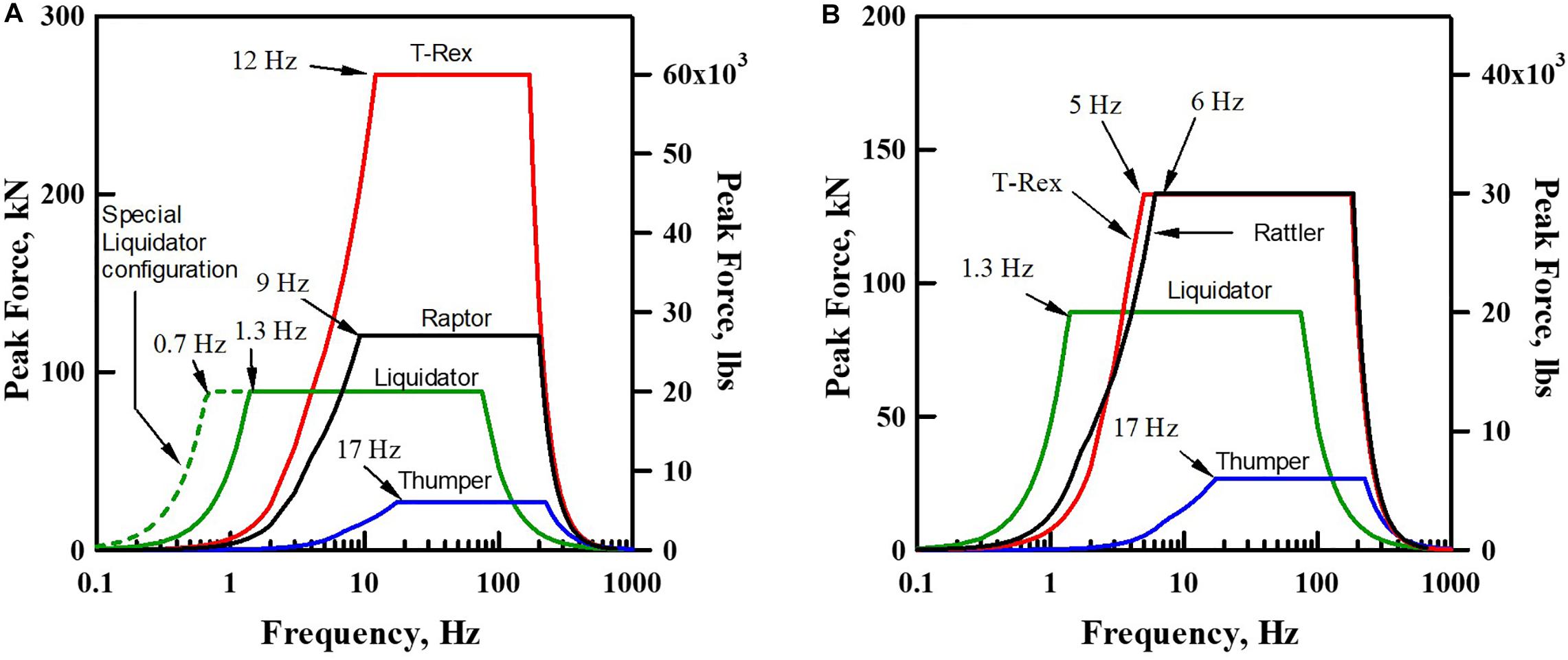
Figure 2. Theoretical force outputs of the five mobile shakers at NHERI@UTexas in the: (A) vertical mode and (B) horizontal mode (Stokoe et al., 2017).
Figure 3. Photographs of the field supply truck, mobile instrumentation trailer and some associated instrumentation available at NHERI@UTexas: (a) Field supply truck and instrumentation trailer, (b) Air-conditioned work space in instrumentation trailer, (c) 1-Hz vertical geophones and cables, (d) Cone penetrometer test equipment, (e) Data Physics analyzers, and (f) Trillium Compact Seismometers and Taurus Digitizers (after Stokoe et al., 2017).
Raptor and Rattler provide intermediate-level force generation. Raptor (Figure 1c) is called a compression-wave (P-wave) shaker in the geophysical exploration community. The maximum vertical force output is about 120 kN, as shown in Figure 2A. Raptor is ideal for situations where Thumper’s force output (discussed below) is not sufficient for the desired testing application and T-Rex’s triaxial shaking capability and/or higher force output is not required. Rattler (Figure 1d) is a horizontal (shear-wave) vibrator mounted on an off-road vehicle. Rattler has a frequency-force response which similar to T-Rex in the shear mode, as shown in Figure 2B. By having two shear-wave vibrators (T-Rex and Rattler), they can be used simultaneously with synchronized force outputs to generate a larger surface area of high shear strains. Thus, for in-situ liquefaction and non-linear soil testing, soil beneath the two shakers, where the instrumentation is placed, can be excited in a nearly plane-strain condition. T-Rex and Raptor can also be used in tandem to create similar conditions in the vertical direction. Since T-Rex, Liquidator, and Rattler are not street-legal, the 26-wheel, tractor-trailer rig, called the Big Rig and shown in Figure 1f, can be used to transport them to the test site.
Thumper (shown in Figure 1f) is the smallest shaker and is mounted on a street-legal truck and has a moderate force output, making it ideal for testing in urban areas. The maximum force output of Thumper in the vertical or horizontal directions is about 27 kN, as shown in Figure 2. With around 2 h of work in the field, Thumper’s shaking direction of shaking can be changed at the test site. Hydraulic take-off connections are provided on T-Rex, Liquidator, and Thumper, which can be used to power other hydraulic equipment. For example, they could be used to run linear hydraulic actuators for in-situ, pushover or pullout testing of superstructure and substructure subassemblages in the field (Stokoe et al., 2017). The hydraulic shakers on the T-Rex, Liquidator, and Thumper vehicles can also be removed and mounted on a structure, while the hydraulics and electronics on the associated truck can be used to run the shaker.
Some of the NHERI@UTexas instrumentation and field support vehicles are shown in Figure 3. The supply truck, shown in Figure 3a, carries fuel and spare parts for the shaker trucks. Additionally, there is a customized Ford cargo van (not shown in Figure 3) and a 2.4 m by 4.8 m instrumentation trailer (shown in Figures 3a,b) that both provide an air-conditioned workspace, data acquisition systems, and electrical power.
The NHERI@UTexas facility also has a significant amount of field instrumentation, including: (1) two primary data acquisition systems (discussed below), (2) 85 1-Hz vertical geophones (Figure 3c), (3) 24 1-Hz horizontal geophones, (4) 6 high-capacity dynamic load cells, (5) 18 triaxial MEMS accelerometers, (6) cone penetrometer test (CPT) equipment and seismic CPT equipment (Figure 3d), and (7) 12 120-s Trillium Compact broadband seismometers (Figure 3f).
The two main data acquisition systems are a 64-channel Data Physics spectrum analyzer system and 10 three-channel Nanometrics Taurus digitizers (with 30 channels in total). The Data Physics system uses the SignalCalc 730 software to generate input signals (sinusoidal, stepped-sine, white noise, frequency sweeps, etc.) that drive the mobile shakers and to record output signals from various sensors. The Data Physics system (shown in Figure 3e) consists of three dynamic signal analyzers, which have a total of 64 channels. The Data Physics analyzers can be set up as three separate units with different sampling rates, or they can be linked together as a single system. The Data Physics spectrum analyzers have the capacity to record data for hours of time at a high sampling rates up to 200,000 Hz. The Data Physics control software can also be used to perform real-time frequency domain calculations and display auto-power spectra, transfer functions, coherency, and phase plots to facilitate reviewing and analyzing data in the field.
If a distributed sensor array is required for a field study, e.g., with sensors hundreds of meters to a km apart, such as for passive surface wave testing and topographic amplification studies, the Nanometrics Taurus digitizers and Trillium seismometers can be used, as shown in Figure 3f. The 10 Taurus digitizers are solar powered, self-sustaining recording stations for three-dimensional (3D) motions. While designed for long-term deployments such as aftershock monitoring, but can also be used for any type of data acquisition where distributed, GPS-synchronized digitizers are required. Other types of sensors can also be connected to the Nanometrics Taurus digitizers, for example, to monitor strain or displacements of buildings and bridges.
Many of the field experimental studies that use the large-scale mobile shakers and associated field equipment at NHERI@UTexas are located outside of the state of Texas, and even some studies have been located outside of the mainland of the United States. The reasons for these remote locations relative to Austin, TX are that the specific ground conditions in particular areas and/or the permanent structures at given locations are the focus of the investigation. Figure 4 shows the previous test locations of NHERI@UTexas mobile shakers since 2004. To lower costs associated with traveling to remote sites, trial studies are often conducted at a local test location called the Hornsby Bend (HB) site. The HB site is located southeast of Austin, about 3.5 km north of the Austin-Bergstrom International Airport. The site, shown in Figure 5a, bordered by the Colorado River. Some open areas on the HB site (highlighted in Figure 5a) are permitted to be used by NHERI@UTexas to conduct research studies related to civil infrastructure projects.
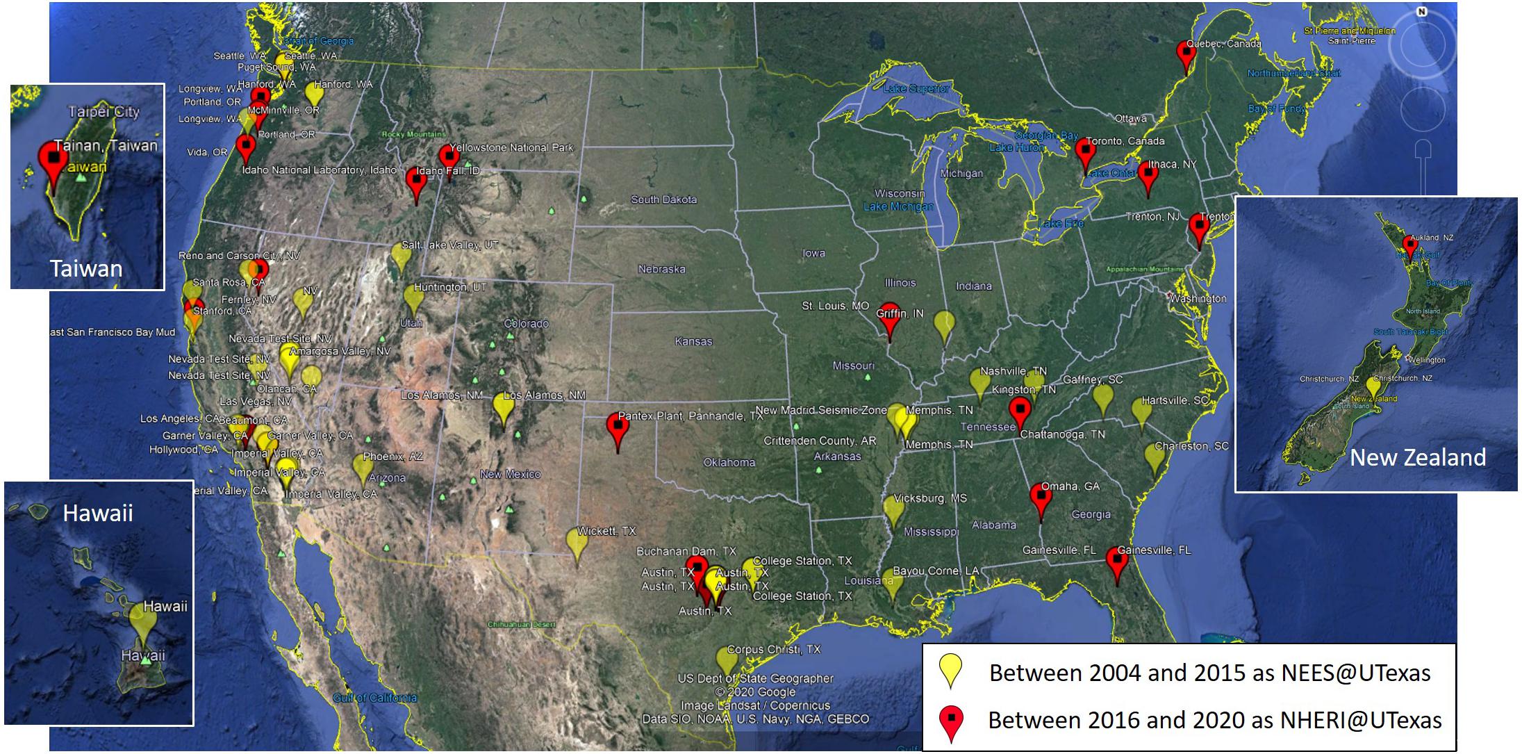
Figure 4. Previous test locations of NHERI@UTexas mobile shakers since 2004 (from Google Earth).
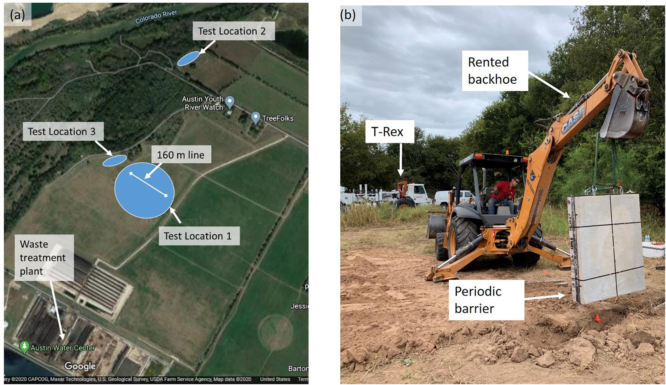
Figure 5. A photograph and a satellite image of the Hornsby Bend (HB) site: (a) Satellite image of the HB site (located about 3.5 km from the Austin-Bergstrom International Airport) and (b) A photograph taken during installation of a periodic barrier at TL2 (from Google Maps).
In the past 12 years, NHERI@UTexas has conducted field studies at three locations at the HB site. These three sites are marked as Test Location 1 (TL1), Test Location 2 (TL2), and Test Location 3 (TL3) in Figure 5b. TL1 is on a large open field. This site is an ideal location for short-term (1 to 3 weeks long) seismic studies that require a large open field. TL2 is located on the north end of the site. Multiple studies have constructed specimens and conducted long-term tests (3 months or longer) at TL2. TL3 is located at the edge of the test field near TL1. Long-term studies are also possible in this area. A photograph taken during installation of a periodic barrier at TL2 is shown in Figure 5b. CPT, Spectral-Analyses-of-Surface-Waves (SASW), and crosshole seismic tests were conducted at multiple locations in the HB site, and all results are available to researchers.
The science plan of NHERI@UTexas is focused on three main challenges. These three main challenges are: “(1) performing deeper, more accurate, higher resolution, 2D/3D subsurface geotechnical imaging, (2) characterizing the non-linear dynamic response and liquefaction resistance of complex geomaterials in situ, and (3) developing rapid, in-situ methods for non-destructive structural evaluation and soil-foundation-structure interaction (SFSI) studies” (Stokoe et al., 2017). We know these challenges are significant, yet we know that the unique equipment resources of NHERI@UTexas can be used to help address them. Below, we describe progress that has been made in each of these areas over the past 4 years using NHERI@UTexas equipment is described, and some of the goals for the future are discussed.
Imagine the limitations of current medical practice without accurate and rapid methods to look inside the body non-intrusively, such as X-ray/CAT Scan, Ultrasound and MRI technologies. Now consider that ultrasound imaging was not widely used in the United States until the 1970s, yet today parents can go to a shopping mall to obtain a color, 3D ultrasound of their yet-to-be-born baby. Amazing! Is it possible that we could make similar strides in subsurface imaging for engineering purposes over the next few decades? Imagine how the ability to develop realistic 3D images of the subsurface, with accompanying elastic properties (shear modulus/Vs, constrained modulus/Vp, Poisson’s ratio, etc.), would influence engineering for more resilient and sustainable infrastructure. The equipment required to make significant progress toward this goal exists within the NHERI@UTexas facility.
While many examples could be given, we will focus on two main areas where advanced subsurface imaging capabilities would help “transform how future civil infrastructure will be designed and how existing civil infrastructure might be rehabilitated”: (1) improved site-specific subsurface models for earthquake ground motion prediction, and (2) continuous 2D/3D in-situ profiling for anomaly detection.
Many recent studies have used multi-depth earthquake ground motion recordings from vertical borehole array sites to investigate our ability to accurately replicate small-strain, linear-viscoelastic site response (i.e., the simplest case, which does not require modeling of soil non-linearity). While these studies have found that 1D ground response analyses (GRA’s) can replicate recorded site response at a few borehole array sites, they have also shown that engineers are generally unable to accurately replicate recorded ground motions at most borehole array sites using available subsurface geotechnical information and 1D GRA’s (e.g., Thompson et al., 2009, 2012; Kaklamanos et al., 2013, 2015; Afshari and Stewart, 2015, 2017; Kaklamanos and Bradley, 2018; Teague et al., 2018). When 1D GRA’s fail to yield accurate predictions of recorded site response, the site is often assumed to be too complex to be accurately modeled as 1D. While 3D numerical GRA’s are possible, there is rarely a true 3D subsurface model that can be used in these analyses. Indeed, even at our most valued borehole array sites in the United States and Japan, we are limited to 1D representations of Vs. This short coming has to change in order for progress to be made in predicting earthquake ground motions.
A recently funded NSF project titled “Collaborative Research: 3D Ambient Noise Tomography (3D ANT) for Natural Hazards Engineering” (Award Number 1930697, PI: K. Tran) is a good example of how advances in 3D subsurface imaging are being investigated using NHERI@UTexas equipment. While the project is still in its early stages, some progress has been made toward the goal of developing a deeper and more spatially extensive 3D Vs model of the Garner Valley Downhole Array (GVDA) site. In October 2019, NHERI@UTexas personnel used Thumper as a high-fidelity controlled seismic source for a full waveform inversion (FWI) study at GVDA. In this study, 196 3-component land seismic sensors were deployed in a 65 m × 65 m array with a uniform 5 m receiver spacing (Figure 6a). The NHERI@UTexas Thumper shaker truck was used to generate broadband frequency sweeps at 84 locations inside and outside of the array. The ultimate goal of this research is to combine the active-source data from Thumper with passive-wavefield ambient noise to generate a 3D Vs model of the site with meter-scale resolution over the top 50- to 100-m of the subsurface. This 3D model has not yet been completed, but the spatial variability of the fundamental site frequency (f0) at GVDA is shown in Figure 6b. From the variability in f0, it is clear that the GVDA site is not 1D. As such, a true 3D Vs model is needed to support 3D GRA’s at this important borehole array site. The call for deeper and more accurate subsurface models for use in seismic ground motion studies continues to grow louder. These types of 3D models, or refinements to pseudo-3D models, are needed beneath many United States cities in high seismicity areas that are underlain by sedimentary basins, such as Los Angeles, Seattle, and Salt Lake City.
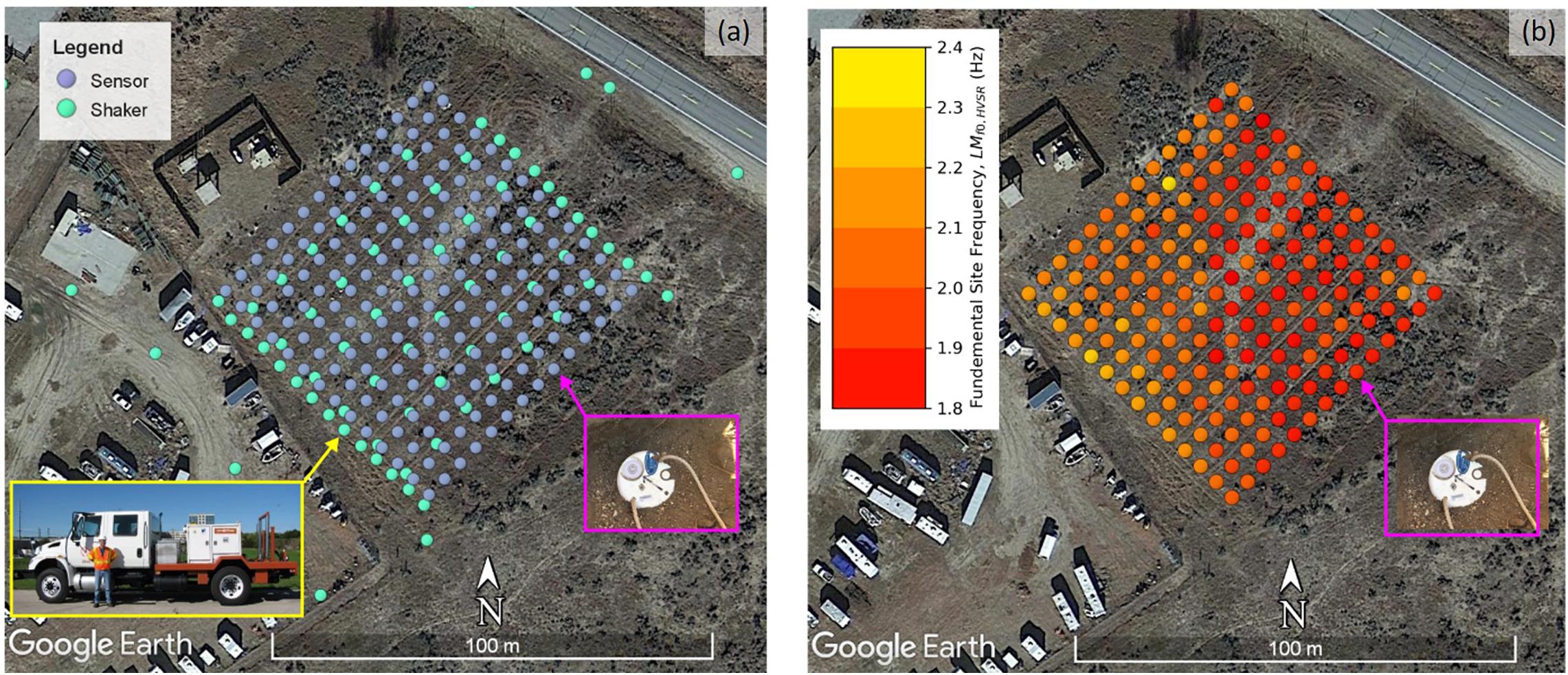
Figure 6. Garner Valley Downhole Array (GVDA) site: (a) 196 3-component land seismic sensors deployed in a 65 m × 65 m array with a uniform 5-m receiver spacing and the NHERI@UTexas Thumper shaker truck that was used to generate broadband frequency sweeps at 84 locations inside and outside of the array, and (b) spatial variability in fundamental site frequency (f0) indicating 3D site conditions.
The ability to rapidly and non-intrusively image the subsurface in 2D/3D for the purpose of site characterization and anomaly detection would be a major scientific and engineering breakthrough. Unknown subsurface anomalies (e.g., cavities/voids, soft/weak zones, dipping layers, buried objects) cause significant problems during and after construction of many types of civil infrastructure [e.g., roads, bridges, buildings, levees, and tunnels; Sirles (2006)]. Consider for example our nation’s levee systems, comprising roughly 100,000 miles of earth embankments designed to protect communities from flooding. This aging levee system is susceptible to damage from natural hazards such as flooding, hurricane inundation, and earthquakes, and the cost to repair or rehabilitate these levees is estimated to be over US$100 billion (ASCE, 2013). The ability to rapidly and reliably evaluate our nation’s levee systems to find anomalies and weak zones would greatly increase the resilience of our civil infrastructure in a cost-effective way. The NHERI@UTexas equipment help address this 2D/3D imaging problem.
Full waveform inversion methods are the most promising way to obtain true 2D/3D subsurface seismic images for engineering purposes. The primary goal of FWI is to reconstruct the near-surface material profile of arbitrarily heterogeneous formations, in terms of the formation’s spatially distributed elastic properties, using stress waves as the probing agent (Kallivokas et al., 2013). FWI is a challenging data-fitting procedure based on full-wavefield modeling to extract quantitative information from all wave types in the recorded seismograms (Virieux and Operto, 2009). FWI requires both a densely spaced grid of sensors and multiple excitation locations from a broadband seismic source, both of which are provided as part of the proposed NHERI@UTexas equipment.
As a means to illustrate progress that is being made in this area, 3D FWI imaging results that were obtained as part of an NSF project titled “Geotechnical Site Characterization with 3D Seismic Waveform Tomography” are presented (Award Number 1850696, PI: K. Tran). Also note that the imaging data for the results presented below, and published in Tran et al. (2020), were collected as part of a NHERI@UTexas user workshop that was held in Newberry, Florida. The Newberry Site consists of medium dense, fine sand and silt underlain by highly variable and karstic limestone, the top of which varies from 2- to 10-m depth across the site. Seismic surveys at the site were conducted by Prof. Tran and the NHERI@UTexas team using 48, 4.5-Hz vertical geophones located in a 4 × 12 grid at 3 m spacing on the ground surface. The seismic energy was created at 65 source locations by the NHERI@UTexas Thumper shaker truck. The final inverted 3D Vp and Vs models, which are 18 m deep × 36 m long × 12 m wide, are shown in Figure 7. The velocity models indicate soft soil layers at shallow depths, underlain by a stiffer weathered limestone layer of variable depth. Several potential voids were identified in the images. In Figure 7, the standard penetration test (SPT) N-values that were collected from a borehole drilled to verify one of the void are also shown. The N-values confirmed that a void does exist in the depth range from about 4 to 7 m.
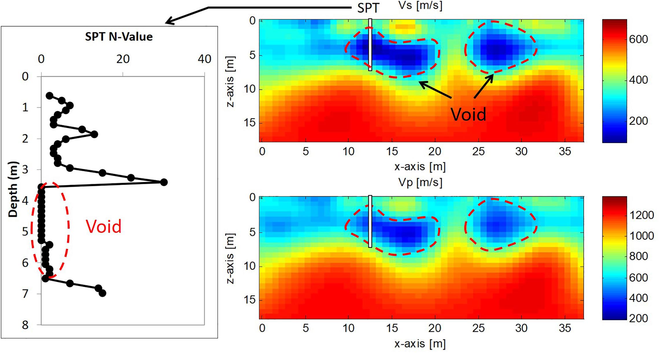
Figure 7. Comparison of FWI seismic and invasive SPT. The inverted Vs and SPT results both show a void at about 4–7 m depth and top of bedrock at 7 m depth (after Tran et al., 2020).
Although these 3D FWI results are excellent, they are limited in terms of their depth of investigation. Future research is needed using the more powerful, low-frequency, active-source mobile shakers of NHERI@UTexas to extend the depth range of FWI for both ground motion studies and subsurface anomaly detection. Furthermore, FWI has the potential to reveal in-situ material damping, which has heretofore been the “holy grail” of in-situ site characterization. However, while significant progress has been made recently toward quantifying uncertainty from non-intrusive surface wave testing (e.g., Vantassel and Cox, 2020), research about quantifying uncertainty in FWI is virtually non-existent. This topic is another area where significant progress remains to be made. Just as in medical imaging, the potential for transformative impact on the design and rehabilitation of civil infrastructure is huge if rapid, 2D/3D in-situ subsurface imaging can be achieved.
Natural geotechnical materials, soil and rock, represent a significant fraction of all materials that impact the performance of our nation’s infrastructure during earthquakes and other natural hazards, such as hurricanes and floods. For example, consider the devastating effects of soil liquefaction and site amplification in almost every significant earthquake. The role of geotechnical materials in hurricanes and floods is also important, and generally controlled by a combination of compacted soils that form levees, dams, or dikes and the underlying natural materials. Poor performance of levees during hurricanes, for instance, can adversely affect large areas due to inundation, such as the failure of levees around New Orleans, LA during Hurricane Katrina in 2005. Unfortunately, natural geotechnical materials are the least investigated, most variable, and least controlled of all materials that form part of the United States infrastructure inventory (Coduto et al., 2015). Therefore, a significant challenge to making our infrastructure resilient and sustainable is characterizing the non-linear dynamic response and liquefaction resistance of complex geomaterials in situ.
Non-linear dynamic soil properties are required in predicting the response of geotechnical and structural systems during earthquakes and hurricanes. The non-linear properties most often required are: (1) the variation of shear modulus (G) and material damping ratio in shear (D) with shear strain (γ), and (2) how these properties vary with soil type and number of cycles of loading. These properties are typically expressed as G-log γ and D-log γ relationships, since shear strains induced during natural hazards can easily range over a factor of 1000 (from below 0.001% to above 1.0%). Before the NEES/NHERI programs at NSF, these dynamic soil properties could not be measured in the field because of the inability to generate controlled, sinusoidal loading over a wide range of strains and number of cycles in the field. Therefore, the field G-log γ and D-log γ relationships were empirically estimated by combining large-strain non-linear measurements from small-scale dynamic laboratory testing of intact or reconstituted soil specimens with limited, low-strain, field seismic testing.
Over the past 16 years, the NEES/NHERI@UTexas mobile shakers have been used to initiate and continue development of a generalized, staged-loading approach by which G-log γ and pore-water pressure–log γ relationships can be measured in situ. This type of in-situ parametric testing is needed: (1) to understand the limitations of the empirical approach, and (2) because many geotechnical materials cannot be readily, or cost-effectively, tested in the laboratory. These materials include: gravelly soils, cemented alluvium, municipal solid waste, and loose gravelly, sandy, and silty soils with non-plastic or plastic fines that are prone to liquefaction. The generalized staged-testing approach involves creating an array of the appropriate sensors in the target material and shaking this material with some type of surface “loading platen.”
In the past 4 years, NHERI@UTexas has been developing two new testing techniques, which focus on increasing the maximum strain level in the instrumented soil zone at depth. The first new technique utilizes two mobile shakers carefully phased together to generate vibration on top of the instrumentation array (after Zhang et al., 2019). This technique was tested in a recent field liquefaction project in the Port of Longview, WA to investigate the liquefaction susceptibility of silty soils. As shown in Figure 8a, T-Rex and Rattler were parked side by side on top of an instrumented array. The vibrational outputs of T-Rex and Rattler were synchronized so that shear strains generated in the instrumented array from both shakers were added on top of each other. An example of the curve of excess pore-water pressure ratio (ru) versus shear strain for this site is shown in Figure 8b. Utilizing two mobile shakers approximately doubled the induced shear strain level, compared to using only one mobile shaker. The second new technique is still under development. This technique will utilize a large –diameter, 3-to-4 flight auger to transfer shear deformations to a deeper depth, as shown in Figure 9. In a proposed study scheduled for 2021, the large auger (about 1.5 m in diameter) will be used to transfer energy from the mobile shaker on the ground surface to the testing depth. With this setup, we expect that the maximum shear strain can reach 0.4% to a depth of 4 m or more below the ground surface.
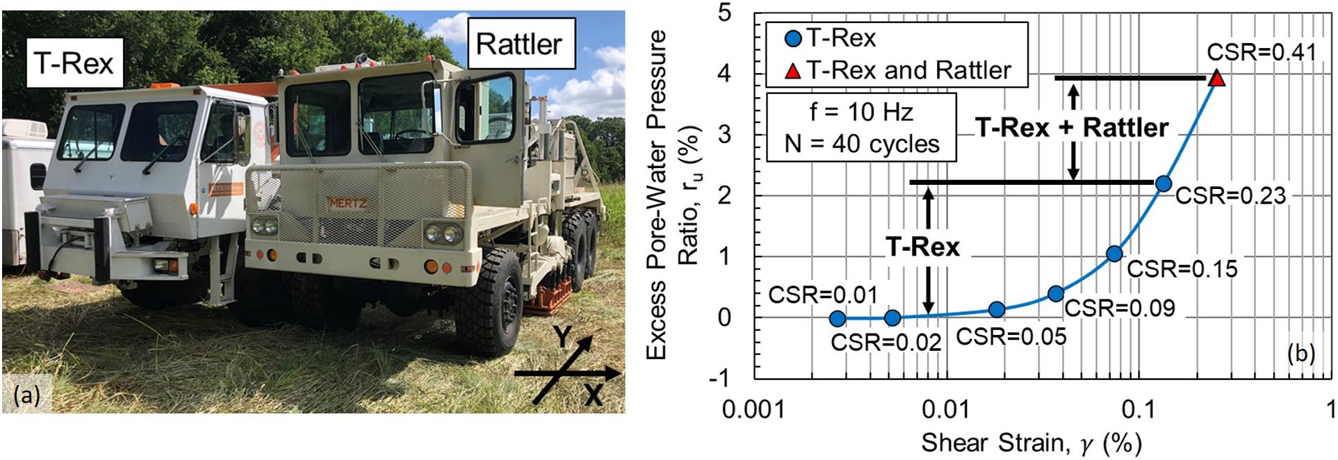
Figure 8. Combined synchronized loading with T-Rex and Rattler in field shaking tests: (a) T-Rex and Rattler parked side by side and (b) Improved dynamic loading creates larger strains (after Zhang et al., 2019).
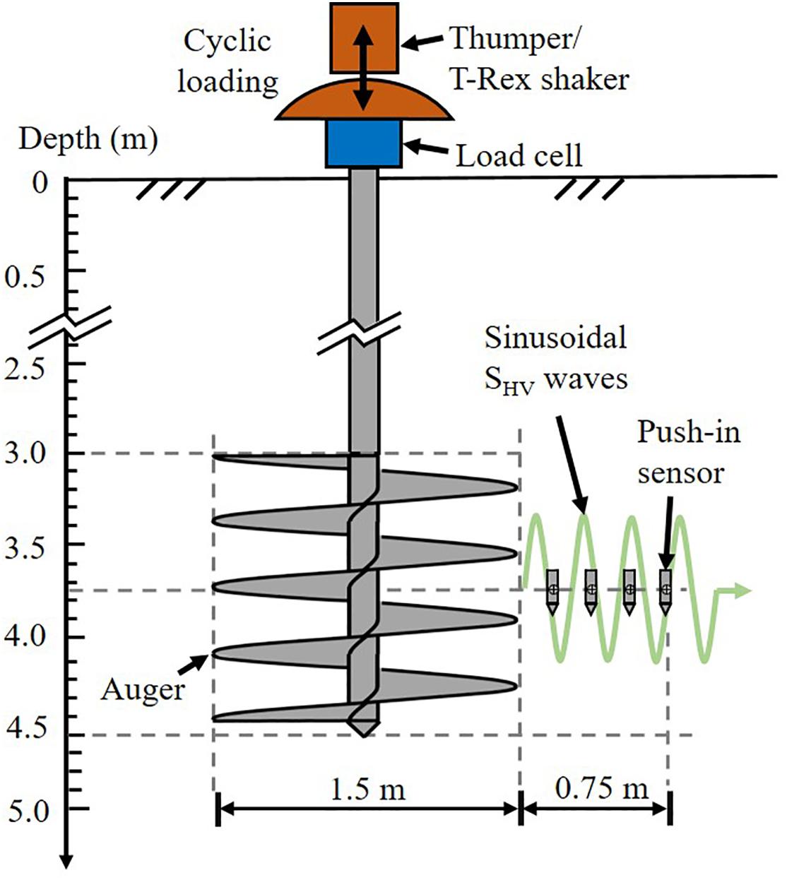
Figure 9. Schematic of deep in-situ liquefaction testing using an auger.
Two recent NSF projects have focused on using NHERI@UTexas equipment to help evaluate new bio-mediated ground improvements methods to mitigate soil liquefaction. A project titled “RAPID Field Assessment of microbially induced carbonate precipitation (MICP)/microbially induced desaturation and precipitation (MIDP) Test Sections” (Award Number 1449501, PI: E. Kavazanjian) investigated soils treated using both the MICP method, and the MIDP method in Toronto, Canada. Results show a limited increase in soil stiffness from both methods. However, the MIDP method was proven effective in de-saturating both sandy and silty soils, and the desaturation was achievable in the field, as shown in Figure 10 (Stokoe et al., 2020). The success of this study paved the way for a second study in Portland, OR on a project titled “RAPID Liquefaction Mitigation of Silts using MIDP and Field Testing with NHERI@UTexas Large Mobile Shakers” (Award Number 1935670, PI: A. Khosravifar). Continued monitoring of the desaturation level at this site by crosshole measurements for about 9 months after the end of treatment indicates that desaturation is persisting.
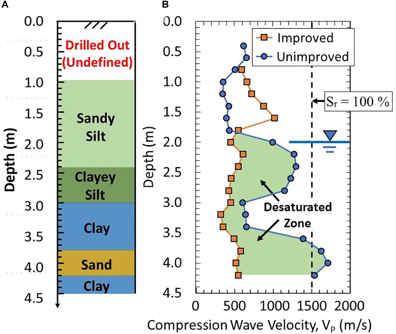
Figure 10. Soil-type and P-wave velocity profiles showing the effectiveness of the microbially induced desaturation and precipitation (MIDP) method to desaturate natural soils: (A) Soil-Type Profile Based on CPT Data and (B) P-Wave Velocity Profiles (Stokoe et al., 2020).
The NHERI@UTexas equipment can also be used to test structural engineering systems in the field. The vast majority of structural engineering experimental research comprises quasi-static, pseudo-dynamic, or shake table testing to characterize the performance and non-linear behavior of structural specimens with idealized boundary conditions. These types of tests, however, tend to ignore or overly idealize complex SFSI behavior that can affect performance of civil infrastructure systems. Experimental research addressing SFSI often involves small-scale structural models (with model-to-prototype scales on the order of 1:30 to 1:100) excited on a shake table or in a centrifuge in containers of perfectly uniform soil. Such small-scale specimens may not reflect realistic construction methods or structural materials and only consider a limited range of perfect soil conditions. While scaled and idealized laboratory experimental research programs are needed to better understand structural behavior, the NHERI@UTexas equipment provide capabilities to test complex, in-situ structure-foundation-soil systems in a range of soil conditions. The NHERI@UTexas shakers can be used to test soil-foundation-structure systems in a variety of ways, including indirect excitation of the structure, by shaking the soil; direct excitation, by driving the shaker onto the structure or by removing the shaker from the truck and attaching it directly to the structure; or by facilitating quasi-static test methods in the field. The shakers were initially designed primarily for use in testing geotechnical systems, such that the larges force outputs are in relatively high frequency ranges compared to most structural systems. Based on the maximum force vs. frequency output of each of the shakers, the shakers may not be able to provide sufficient dynamic excitation to elicit non-linear, damaging behaviors in large-scale structure, which may desirable if testing in-service infrastructure. If needed, smaller-scale structural specimens can be designed considering the shakers’ force vs. frequency output capacities if non-linear behavior is of interest.
A NSF-funded project titled “EAGER: Informing Infrastructure Decisions through Large-Amplitude Forced Vibration Testing” (Award Number 1650170, PI: N. Gucunski) is an example of using the mobile shakers for direct and indirect dynamic testing of a soil-foundation-structure system in the field. The researchers in this study hypothesized that conventional approaches for structural identification using low-force or ambient vibrations do not provide sufficient excitation to investigate soil-foundation interactions or to overcome unintended composite action and stick-slip mechanisms in the structure. Thus, larger, controlled shaking levels, such as those provided by the NHERI@UTexas shakers, are needed for more robust field investigation of dynamic SFSI on large-scale structures. To this end, the T-Rex shaker was employed to dynamically test a soil-foundation-structure system, in this case an overpass bridge, located in Hamilton Township, New Jersey. T-Rex was used to input vertical, longitudinal, and transverse shaking at various locations on the bridge deck and on the ground around the bridge. 3D geophones and accelerometers were placed at various locations on the deck, bent, abutment, and ground to measure the 3D responses (Figure 11).
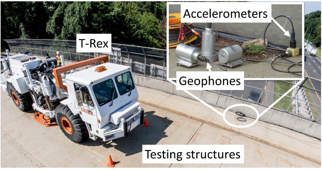
Figure 11. T-Rex structural testing with 3D arrays of geophone and accelerometers.
Key findings from this study (Farrag et al., 2018, 2019a,b) include evaluation of the effects of controlled, low-level shaking compared to conventional ambient vibrations, as well as evaluation of dynamic SFSI through comparison with numerical models. Figure 12 shows an example of how forced vibrations from T-Rex are better at capturing key dynamic structural behaviors, such as transverse rocking (as indicated by the 180 degree phase angle in Figure 12A), compared to ambient vibrations (Figure 12B). Additionally, numerical models simulating dynamic SFSI behaviors via frequency-dependent translational and rotational springs at the base of the bridge piers were better able to capture the two dominant modes of lateral vibration observed during the forced-vibration tests, compared to conventional modeling approaches using fixed-base supports. While this test program was a successful demonstration of using mobile shakers to better understand SFSI effects in large-scale structures, further in-situ field testing of complex systems is necessary to better address research needs related to structure-foundation-soil system behavior and in-situ structural dynamic evaluation.
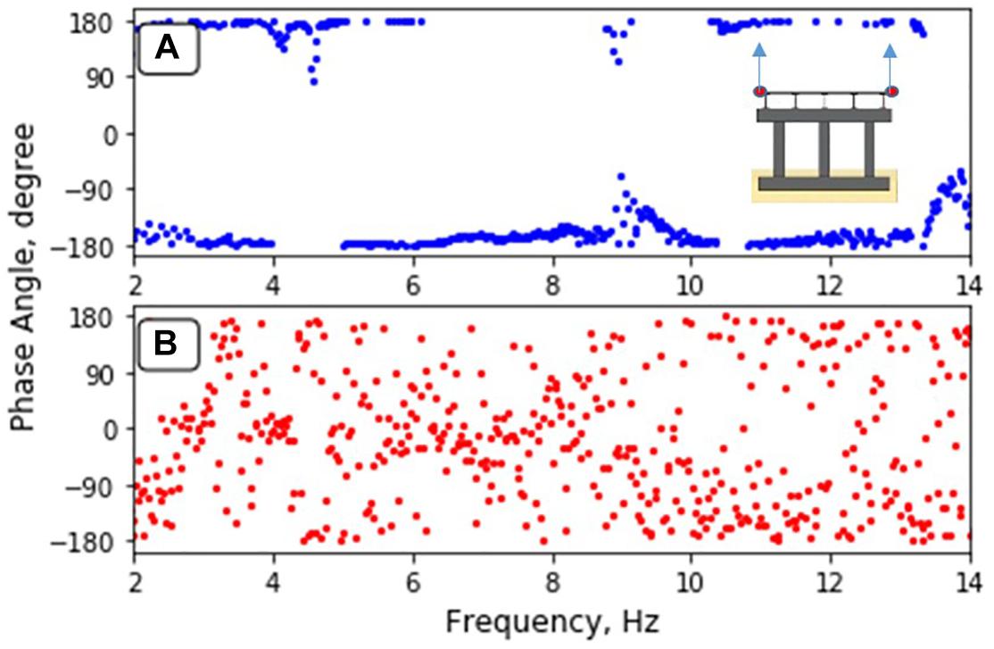
Figure 12. Phase angles between the vertical response of the east and west sides of the bridge deck under (A) lateral transverse loading from T-Rex and (B) ambient vibrations.
Specialized, mobile field equipment that is available at the NHERI@UTexas equipment facility for dynamically and/or cyclically loading of the natural and built environments is presented in this article. Five large, hydraulically controlled shakers, a tractor-trailer to transport the largest shakers, field-support vehicles, and a large collection of field instrumentation and sensors are available to researchers around the world through the NSF NHERI shared-use policy. The science plan of NHERI@UTexas is focused on three main challenges. These three main challenges are: “(1) performing deeper, more accurate, and higher resolution 2D/3D subsurface geotechnical imaging, (2) characterizing the non-linear dynamic response and liquefaction resistance of complex geomaterials in situ, and (3) developing rapid, in-situ methods for non-destructive evaluations and SFSI studies” (Stokoe et al., 2017). Examples of the uses of this unique equipment in these three areas as well as examples of improvements to the equipment to increase the field testing capabilities are presented.
The original contributions presented in the study are included in the article/supplementary material, further inquiries can be directed to the corresponding author/s.
Written informed consent was obtained from the individual(s) for the publication of any potentially identifiable images or data included in this article.
All authors listed have made a substantial, direct and intellectual contribution to the work, and approved it for publication.
The authors declare that the research was conducted in the absence of any commercial or financial relationships that could be construed as a potential conflict of interest.
The authors would like to thank the U.S. National Science Foundation for the financial support to develop and operate the NEES@UTexas and NHERI@UTexas Equipment Sites under grants CMS-0086605, CMS-0402490, and CMMI-1520808. The authors also would like to thank the following researchers who utilized NHERI@UTexas equipment facility including Drs. Arash Khosravifar, Armin Stuedlein, Dennis Hiltunen, Diane Moug, Edward Kavazanjian, Khiem Tran, Leon van Paassen, Matt Evans, and Nenad Gucunski. Special thanks also goes to the graduate students and staff members at the University of Texas at Austin who assisted in the field work, including Mr. Benchen Zhang, Ms. Julia Roberts, Mr. Sungmoon Hwang, Mr. Gunwoong Kim, Ms. Reihaneh Hosseini, Mr. Zhongze Xu, Mr. Cecil Hoffpauir, Mr. Andrew Valentine, Mr. Curtis Mullins, and Mr. Robert Kent.
Afshari, K., and Stewart, J. P. (2015). “Effectiveness of 1D ground response analyses at predicting site response at California vertical array sites,” in Proc., SMIP15 Seminar on Utilization of Strong-Motion Data, California Strong Motion Instrumentation Program (CSMIP), Davis, CA, 23–40.
Afshari, K., and Stewart, J. P. (2017). “Implications of California vertical array data for the analysis of site response with 1D geotechnical modeling,” in A Report on Research Conducted Under Grant no. 1014-961 From California Strong Motion Instrumentation Program (CSMIP), Sacramento, CA: California Geological Survey.
ASCE (2013). Report Card for America’s Infrastructure. Reston, VA: American Society of Civil Engineers.
Coduto, D. P., Kitch, W. A., and Yeung, M. R. (2015). Foundation Design: Principles and Practices, 3rd Edn. Upper Saddle River, NJ: Prentice Hall.
Farrag, S., Gucunski, N., Cox, B. R., Menq, F., Moon, F., and DeVitis, J. (2019a). “Assessing the significance of dynamic soil-structure interaction by using large-amplitude mobile shakers,” in ASCE Geo-Congress 2019: 8th International Conference on Case Histories in Geotechnical Engineering, Philadelphia, PA, 24–27.
Farrag, S., Gucunski, N., Cox, B. R., Menq, F., Moon, F., and DeVitis, J. (2019b). “Use of large-amplitude mobile shakers for structural identification of bridges,” in ICIMART’19-3rd International Conference on Infrastructure Management, Assessment and Rehabilitation Techniques, Sharjah, 5–7.
Farrag, S., Gucunski, N., Moon, F., DeVitis, J., Cox, B. R., and Menq, F. (2018). “Inferring dynamic characteristics of a bridge through numerical simulation and low-magnitude shaking as a global NDE method,” in Proc. of 2018 SMT and NDE-CE ASNT Topical Conference, New Brunswick, NJ, 27–29.
Kaklamanos, J., Baise, L. G., Thompson, E. M., and Dorfmann, L. (2015). Comparison of 1D linear, equivalent-linear, and nonlinear site response models at six KiK-net validation sites. Soil Dyn. Earthq. Eng. 69, 207–215. doi: 10.1016/j.soildyn.2014.10.016
Kaklamanos, J., and Bradley, B. A. (2018). Challenges in predicting seismic site response with 1D analyses: conclusions from 114 KiK-net vertical seismometer arrays. Bull. Seismol. Soc. Am. 108, 2816–2838. doi: 10.1785/0120180062
Kaklamanos, J., Bradley, B. A., Thompson, E. M., and Baise, L. G. (2013). Critical parameters affecting bias and variability in site-response analyses using KiK-net downhole array data. Bull. Seismol. Soc. Am. 103, 1733–1749. doi: 10.1785/0120120166
Kallivokas, L. F., Fathi, A., Kucukcoban, S., Stokoe, K. H., Bielak, J., and Ghattas, O. (2013). Site characterization using full waveform inversion. Soil Dyn. Earthq. Eng. 47, 62–82. doi: 10.1016/j.soildyn.2012.12.012
Sirles, P. C. (2006). NCHRP Synthesis 357: Use of Geophysics for Transportation Projects. Washington, DC: Transportation Research Board of the National Academies.
Stokoe, K. H., Cox, B., Clayton, P., and Menq, F. (2017). “NHERI@UTEXAS experimental facility: large-scale mobile shakers for natural-hazards field studies,” in 16th World Conference on Earthquake, Santiago: Chile.
Stokoe, K. H., Hwang, S., Cox, B. R., Menq, F., Roberts, J., and Park, K. (2019). “Field studies of the natural and built environments using large mobile shakers,” in 7th International Conference on Earthquake Geotechnical Engineering (7 ICEGE), Roma, 17–20.
Stokoe, K. H., Menq, F., Zhang, B., and Gunwoong, K. (2020). “Field assessment of microbially-induced carbonate precipitation (MICP) and microbially-induced desaturation and precipitation (MIDP) methods,” in Geotechnical Engineering Report GR20-01, Austin, TX: The University of Texas at Austin.
Teague, D. P., Cox, B. R., and Rathje, E. R. (2018). Measured vs. predicted site response at the Garner Valley downhole array considering shear wave velocity uncertainty from borehole and surface wave methods. Soil Dyn. Earthq. Eng. 113, 339–355. doi: 10.1016/j.soildyn.2018.05.031
Thompson, E. M., Baise, L., Kayen, R., and Guzina, B. (2009). Impediments to predicting site response: seismic property estimation and modeling simplifications. Bull. Seismol. Soc. Am. 99, 2927–2949. doi: 10.1785/0120080224
Thompson, E. M., Baise, L., Tanaka, Y., and Kayen, R. (2012). A taxonomy of site response complexity. Soil Dyn. Earthq. Eng. 41, 32–43. doi: 10.1016/j.soildyn.2012.04.005
Tran, K. T., Nguyen, T. D., Hiltunen, D. R., Stokoe, K. H., and Menq, F. (2020). 3D full-waveform inversion in time-frequency domain: field data application. J. Appl. Geophys. 178:104078. doi: 10.1016/j.jappgeo.2020.104078
Vantassel, J. P., and Cox, B. R. (2020). A procedure for developing uncertainty-consistent vs profiles from inversion of surface wave dispersion data. arXiv [Pre-print]. (submitted to Soil Dynamics and Earthquake Engineering). Available online at: https://arxiv.org/abs/2007.09775 (accessed October 18, 2020).
Virieux, J., and Operto, S. (2009). An overview of full-waveform inversion in exploration geophysics. Geophysics 74, WCC1–WCC26. doi: 10.1190/1.3238367
Keywords: NHERI@UTexas, mobile shakers, in situ testing, subsurface imaging, liquefaction testing, soil-structure interaction
Citation: Stokoe KH II, Cox BR, Clayton PM and Menq F (2020) NHERI@UTexas Experimental Facility With Large-Scale Mobile Shakers for Field Studies. Front. Built Environ. 6:575973. doi: 10.3389/fbuil.2020.575973
Received: 24 June 2020; Accepted: 16 October 2020;
Published: 09 November 2020.
Edited by:
Carlos Estuardo Ventura, The University of British Columbia, CanadaReviewed by:
Michael Olsen, Oregon State University, United StatesCopyright © 2020 Stokoe, Cox, Clayton and Menq. This is an open-access article distributed under the terms of the Creative Commons Attribution License (CC BY). The use, distribution or reproduction in other forums is permitted, provided the original author(s) and the copyright owner(s) are credited and that the original publication in this journal is cited, in accordance with accepted academic practice. No use, distribution or reproduction is permitted which does not comply with these terms.
*Correspondence: Kenneth H. Stokoe II, ay5zdG9rb2VAbWFpbC51dGV4YXMuZWR1; Farnyuh Menq, ZnltZW5xQHV0ZXhhcy5lZHU=
Disclaimer: All claims expressed in this article are solely those of the authors and do not necessarily represent those of their affiliated organizations, or those of the publisher, the editors and the reviewers. Any product that may be evaluated in this article or claim that may be made by its manufacturer is not guaranteed or endorsed by the publisher.
Research integrity at Frontiers
Learn more about the work of our research integrity team to safeguard the quality of each article we publish.