 Ross W. Boulanger
 Daniel W. Wilson
 Bruce L. Kutter2
94% of researchers rate our articles as excellent or good
Learn more about the work of our research integrity team to safeguard the quality of each article we publish.
Find out more
REVIEW article
Front. Built Environ., 22 July 2020
Sec. Earthquake Engineering
Volume 6 - 2020 | https://doi.org/10.3389/fbuil.2020.00121
This article is part of the Research TopicNatural Hazards Engineering Research Infrastructure (NHERI) 2016-2020: Mitigating the Impact of Natural Hazards on Civil Infrastructure and CommunitiesView all 16 articles
The 9-m and 1-m radius geotechnical centrifuges at the Natural Hazards Engineering Research Infrastructure (NHERI) facility at the University of California at Davis provide the national research community with open access to unique and versatile modeling capabilities for advancing methods to predict and improve the performance of soil and soil-structure systems affected by earthquake, wave, wind, and storm surge loadings. Large-scale centrifuge models are particularly effective for the building of basic science knowledge, the validation of advanced computational models from the component to the holistic system level, and the validation of innovative soil remediation strategies. The capabilities and unique role of large-scale centrifuge modeling are illustrated using three example research projects from the shared-use NHERI facility. Education impacts stemming from operations activities and coordination of activities by the center’s user base are discussed. Future directions and opportunities for research using the NHERI facilities are discussed.
Centrifuge modeling addresses a fundamental challenge in the scaled physical modeling of geotechnical structures – the need for proper modeling of stress conditions given that most soil properties are dependent on effective confining stress. Scale models executed at 1 g (i.e., earth’s gravitation field) provide only a qualitative evaluation of how full-scale geotechnical structures respond to different loadings because the effective stress conditions and hence soil properties (e.g., stiffness, strength, and dilatancy) are so different. The enhanced gravitational field imposed during a centrifuge test allows for stress similitude between the model and full-scale prototype, such that the response of a scaled centrifuge model to different loadings is more representative of the response expected under field-scale conditions. For example, the profile of vertical effective stress in a 0.6-m thick layer of soil at 50 g is equivalent to those in a 30-m thick layer of soil at 1 g. Centrifuge modeling also offers scaled modeling advantages for other physical processes where self-weight body forces are important, including various porous media, fluid, and gas phenomena (e.g., Taylor, 1995). Scaling laws and questions of similitude have accordingly been developed for a wide range of physical phenomena as they have been examined over the years (Garnier et al., 2007). In this manner, centrifuge modeling has proven invaluable for identifying complex mechanisms and validating computational models across a broader spectrum of conditions than is generally feasible with 1 g field-scale modeling.
Geotechnical centrifuge modeling technology has evolved through several stages over the past century, as described for example in Craig et al. (2015). The earliest reported experiments were in the US and USSR in the 1930s. Early pioneers around the world accomplished notable advances over the next four decades. The 1970s and 1980s brought rapid advances in centrifuge equipment, modeling techniques, and instrumentation, which led to a growth in utilization and increased awareness of centrifuge modeling capabilities in the broader civil engineering discipline. The International Society of Soil Mechanics and Foundation Engineering (now ISSMGE) recognized the growth by establishing an international technical committee on centrifuge modeling in 1981. Centrifuge modeling has continued to see rapid advances in modeling techniques and instrumentation, which has led to higher-resolution data and improved scientific findings, which in turn has fueled expansion in the range of problems that could be explored. Today, centrifuge modeling is firmly established as an essential tool for geotechnical research. This is perhaps best reflected through a recent communication with an NSF program director who noted that reviewers in the 1980s and 1990s asked, “Why would you use centrifuge modeling for this problem,” whereas reviewers in the 2000s and 2010s asked, “Why are they not using centrifuge modeling for this problem?”
The centrifuge modeling facilities at UC Davis have similarly evolved over the past four decades. The geotechnical group first acquired a 1-m radius beam centrifuge in 1975. This centrifuge, still in use today, can subject about 50 kg of soil (typical dimensions of 178 mm deep, 560 mm long, and 280 mm wide) to a centrifugal acceleration of about 100 g, which represents a prototype soil layer thickness as great as 18 m. Its servo-hydraulic shaker, commissioned in 1988, was one of the first hydraulically driven shakers to be mounted on a geotechnical centrifuge. In 1983, the Center for Geotechnical Modeling (CGM) was established to develop and manage a 9-m radius “National Geotechnical Centrifuge” in partnership with NASA Ames and with support from the National Science Foundation (NSF awards 7813922 and 7826122). The 9-m centrifuge was constructed at a NASA Ames Research Center before being moved to UC Davis in 1986, where the first experiments were executed with the centrifuge rotating in an unenclosed space. With continuing effort, the 9-m centrifuge and supporting facilities were enhanced by completion of an enclosure rotunda in 1989, commissioning of a servo-hydraulic shaking table in 1995, and over $5 M of major upgrades from 2000 to 2004 with funding from the NSF through the George E. Brown Jr. Network for Earthquake Engineering Simulation (NEES). The NEES improvements included upgrades to the centrifuge drivetrain, shaking table upgrades, new model containers, advanced data acquisition systems, high-speed cameras, visualization tools, geophysical tools, and aerodynamic modifications to the enclosure. With those modifications, the large centrifuge was capable of subjecting about 1550 kg of soil (a common container has dimensions of 686 mm deep, 1722 mm long, 686 mm wide) to a centrifugal acceleration of about 75 g, which represents a prototype soil layer thickness as great as 51 m. The CGM has subsequently maintained the 9-m and 1-m radius centrifuges at the state of the art through continuous performance improvements while operating as a national shared-use, open-access facility under NSF funding through NEES from 2004 to 2014 and through the Natural Hazards and Engineering Research Infrastructure (NHERI) program from 2016 to present. Photographs in Figures 1, 2 provide a full side view of the 9-m centrifuge, a view of a model container with in-flight cone penetration testing equipment mounted on the end of the 9-m centrifuge arm, and two examples of complex models being constructed for testing on the 9-m centrifuge. Details on the facility history, capabilities, and equipment performance specifications over the years can be found in Wilson et al. (1997, 2010) and Wilson and Allmond (2014) and at the CGM1 and NHERI DesignSafe-CI2 websites.
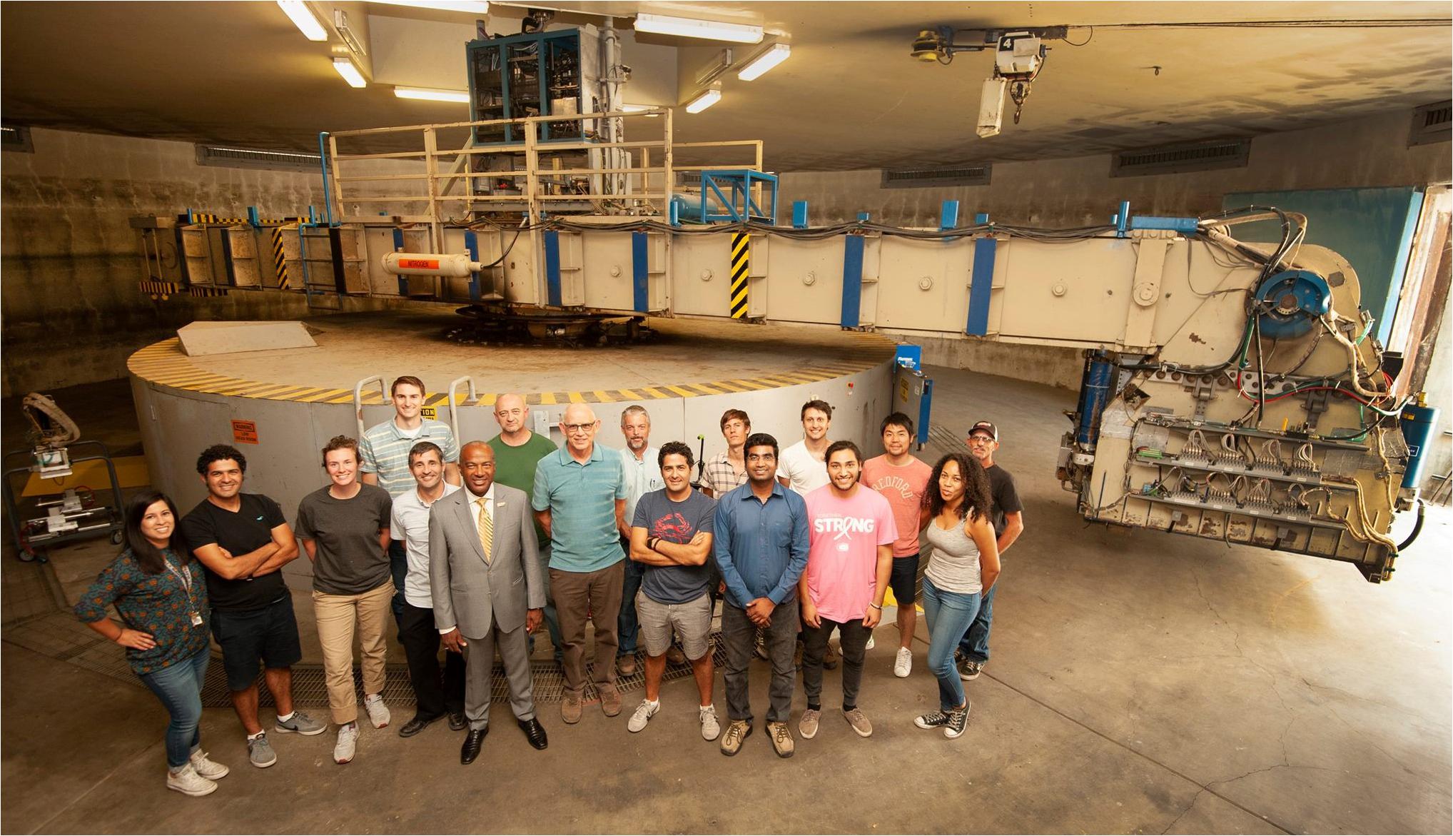
Figure 1. NHERI 9-m radius geotechnical centrifuge at UC Davis in 2019 (photo by Gregory Urquiaga).
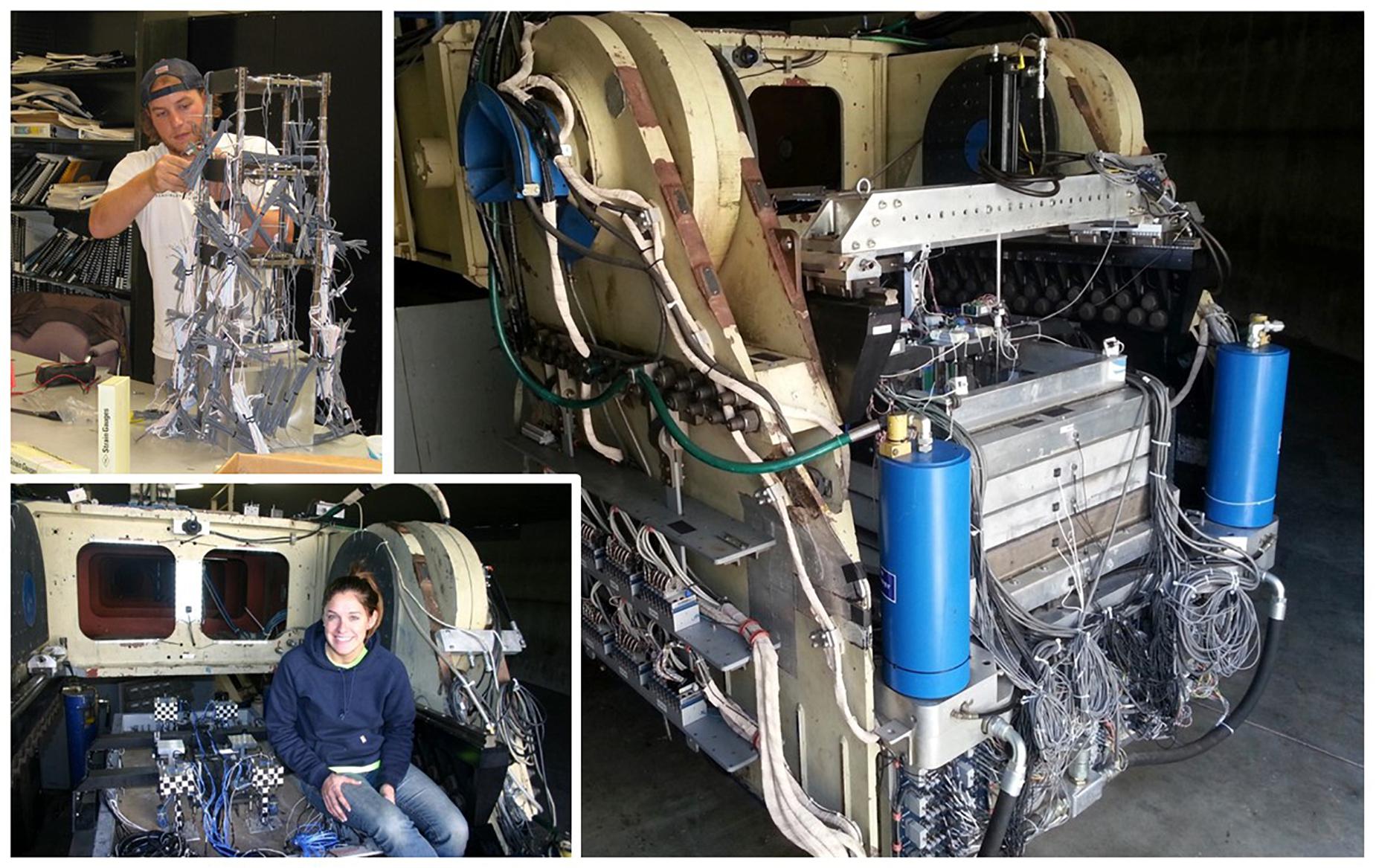
Figure 2. Examples of model testing on the 9-m centrifuge: nonlinear multi-story structure-soil-structure interaction (top left insert), multiple rocking foundation systems (lower left insert), and in-flight cone penetration testing actuator mounted on the gantry (right).
This paper describes the capabilities of the NHERI Centrifuge Facility and the essential role of geotechnical centrifuge modeling for advancing methods to predict and improve the performance of soil and soil-structure systems affected by earthquake, wave, wind and storm surge loadings. Three example projects are used to demonstrate that large-scale models with holistic levels of complexity have produced: (1) uniquely detailed or first-ever measurements of key mechanisms that could not be measured by other means, (2) essential validation for computational models, and (3) major broader impacts for science and society. The three projects are a submerged tunnel surrounded by liquefiable sand backfill, rocking responses of shallow foundations for buildings and bridges subjected to earthquake loading, and liquefiable soil profiles remediated using microbially induced calcite precipitation (MICP). Broader impacts stemming from the NHERI centrifuge facility operations activities and coordination of activities by the center’s user base are described. Lastly, potential future directions and opportunities for research using the NHERI facilities are discussed.
The centrifuge provides a testing environment with an enhanced gravitational field, in which users execute experiments of their own design. New and novel experimental designs are frequently required to address the scientific needs of the researchers, which leads to ongoing improvements and expansions in the on-arm testing capabilities. New experimental designs can be challenging because the enhanced gravitational field can impose significant demands on structural components, mechanic devices (e.g., actuators, remote tools), model containers, and electronic devices, with the associated challenge that commercially available products may not function adequately on the centrifuge, leading to the need for re-designs and modifications. In many cases, a common interest in an emerging technology across research teams has enabled the pooling/leveraging of research funds to expand capabilities in ways that benefit multiple teams.
The three research studies described in the following sections illustrate a subset of the centrifuge modeling capabilities at the CGM facilities. Over eighty research projects, each involving anywhere from a few to dozens of centrifuge experiments, have used the CGM centrifuge facilities. Owing to the uniqueness of the shaking table, most experiments executed to date at UC Davis have focused on seismic applications, including aspects of liquefaction (triggering, lateral spreading, levee/embankment deformations, quay wall deformations), ground improvements (densification, drainage, grouting, soil-cement reinforcements, bio-cementation, bio-desaturation), soil-structure interaction (shallow and deep foundations in soft or liquefiable soils for buildings, bridges, tanks, quay walls), buried structures (lateral pressures and kinematic demands on subway tunnels and stations), seismic site response (sands, soft clays, organic soils), mechanically stabilized earth retaining walls, geo-synthetic liner systems for waste containment, and water-structure-soil interaction for buried reservoirs. Other research projects have examined offshore foundation systems (wave, wind, and seismic loading of jack-up structures, suction caissons, subsea manifolds), in-situ characterization of challenging soils (gravelly soils, interbedded soils, fly ash), novel foundation systems (grouted helical anchors), residual strength of clay slickensides in landslides, tsunami effects on coastal stability, bio-inspired stress-state manipulation for soil penetration, and bio-inspired root-type foundations. Regardless of the application, common objectives include the exploration of fundamental mechanisms, the use of sensor arrays with inverse analyses techniques to quantify key mechanisms, and the use of the data for validation of analytical/computational models. Data from past research projects have been archived for public access at the CGM and DesignSafe websites. A review of the literature indicates the available data has been re-used in at least 110 publications by different researchers around the world, recognizing that data re-use is likely under-counted by our current manual processes.
The Bay Area Rapid Transit (BART) Transbay Tube (TBT) is a 6-km long immersed cut-and-cover subway tunnel that connects Oakland to San Francisco, California. Seismic risk evaluations identified a concern that earthquake-induced liquefaction of the loose sand and gravel backfills surrounding the tunnel (Figure 3) could result in tunnel uplift and damage to the tunnel. Predicting the tunnel uplift and extent of damage in an earthquake, however, was hampered by limited scientific understanding of the deformation mechanisms (Figure 4) and the lack of data against which the numerical modeling procedures could be validated. Decisions regarding remediation alternatives depended on developing confidence in the analysis methods, and thus the design team recommended physical model testing be performed to quantify deformation mechanisms and validate/evaluate the numerical modeling procedures. The centrifuge and numerical modeling work is described in Chang et al. (2008), Chou et al. (2011), and Kutter et al. (2008), with subsequent reanalysis of the data in Tasiopoulou et al. (2019).
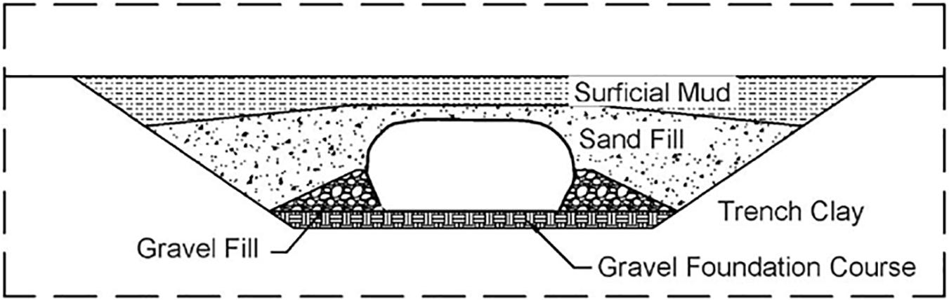
Figure 3. Configuration of the BART Transbay tube and backfill materials (Reproduced from Kutter et al., 2008 with permission from ASCE).
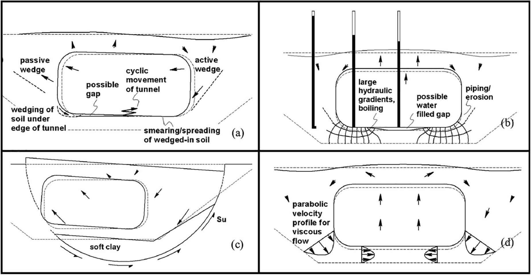
Figure 4. Four uplift mechanisms: (a) ratcheting, (b) pore water migrations, (c) bottom heave, and (d) viscous flow of liquefied soil (Reproduced from Chou et al., 2011 with permission from ASCE).
Large-scale centrifuge models were selected as the preferred approach for physical modeling because the large model container (1.8 m long, 0.7 m wide, and 0.6 m deep) facilitated construction of a model with appropriately complex geometric and stratigraphic details to reflect the real design scenarios, as well as the placement of dense instrumentation arrays for quantifying the different deformation mechanisms through inverse analyses. Each physical model was constructed in a rigid container with polycarbonate windows to view the model cross-section, such as is visible in the photograph in Figure 5. The model tunnel rested on a thin bedding layer of coarse sand at the bottom of trench within the foundation clay. The trench backfill was coarse sand to about mid-height of the tunnel, and then fine sand to above the tunnel crown. A layer of low-permeability fine-grained soil covered the surface of the model. The test was executed at a centrifugal acceleration of 40 g to simulate the prototype tunnel section of approximately 15-m wide by 7-m high. The instrumentation included dense arrays of accelerometers and pore pressure transducers that would be used to define mechanisms, and novel non-contacting proximity transducers were used to measure tunnel uplift during shaking.
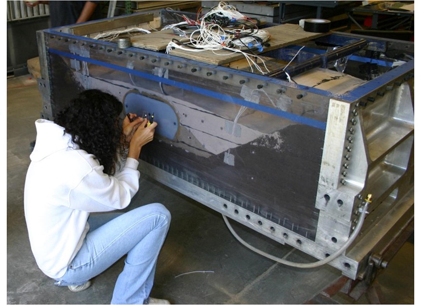
Figure 5. Preparation of the BART Transbay tube model in the rigid glass-walled container.
The centrifuge experiments provided quantitative insights on fundamental mechanisms and the basis for validation of nonlinear dynamic analysis procedures. The fundamental mechanisms that could contribute to tunnel uplift were identified as ratcheting, pore water migration, bottom heave, and viscous flow of liquefied soil (Figure 4). Inverse analyses of the dense instrumentation array data were used to define the transient seepage volumes in the soil and the lateral and vertical force versus displacement responses of the tunnel. The inverse analyses assume the governing differential equations and then use the discrete sensor data and interpolation functions to numerically compute terms that cannot be measured directly. The centrifuge data and inverse analysis results provided quantitative data on the relative contributions of different mechanisms to tunnel uplift, and provide a basis to evaluate numerical modeling limitations associated with pore pressure diffusion in layered soils, possible formation of water films or blisters at the tunnel-soil interface, localized slip at the tunnel-soil interface, shear deformations in liquefied soils at near zero effective stress, and sedimentation (volumetric) strains in liquefied soils. The design team used the data to evaluate/validate two different numerical modeling procedures, one using the finite element platform OpenSees with the multiple yield surface constitutive models by Elgamal et al. (2002) and another using the finite different platform FLAC (Itasca Consulting Group Inc, 2006) with the UBCSAND constitutive model (Beaty and Byrne, 1998). The same data were later re-used by several members of the design team in evaluating updated modeling procedures using FLAC with the PM4Sand constitutive model (Tasiopoulou et al., 2019). The numerical simulations were found to approximate the dynamic response, tunnel uplift, and sand deformation patterns around the tunnel (Figure 6).
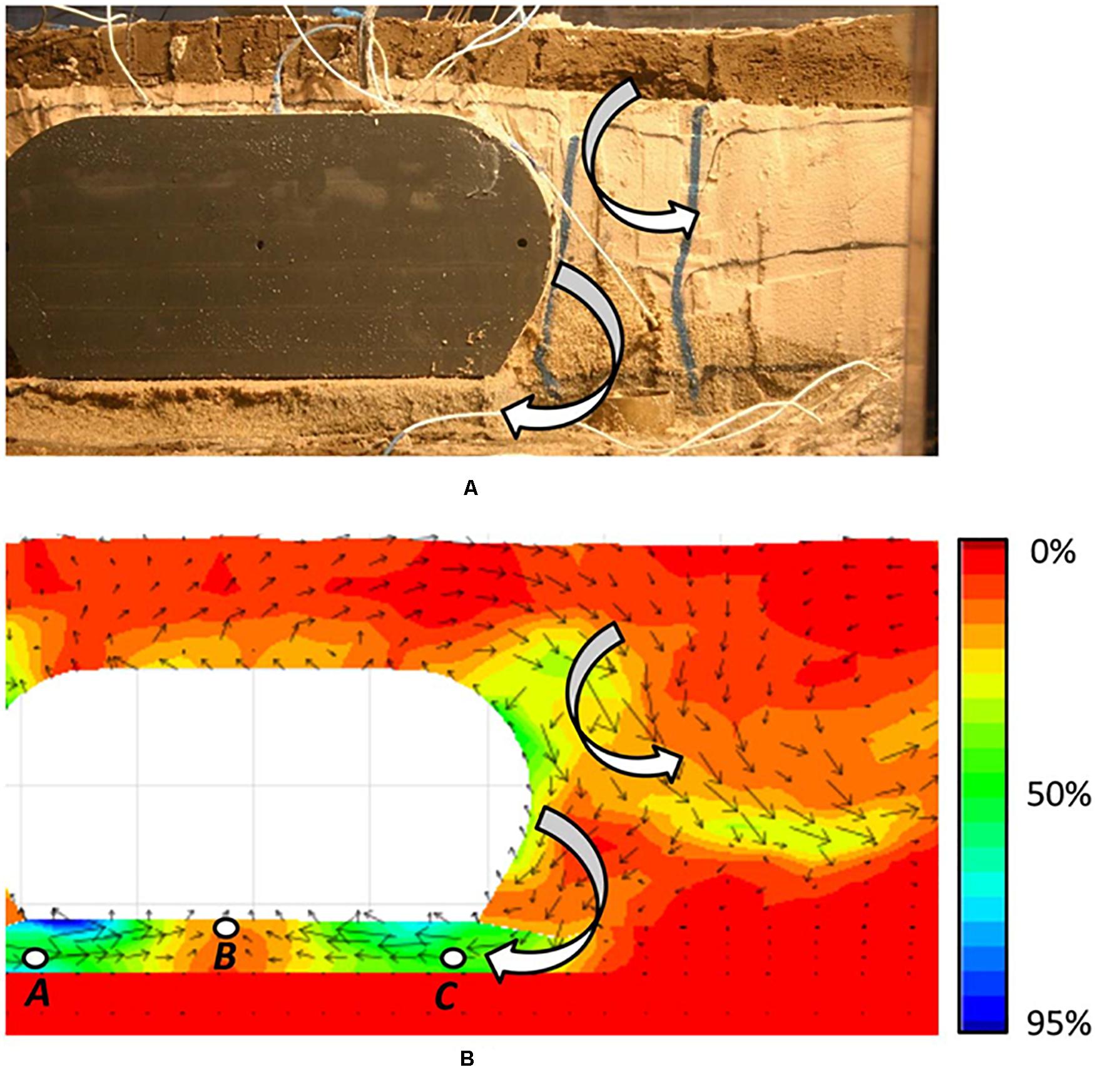
Figure 6. Displacement of sand toward and beneath the tunnel from (A) experimental observation; and (B) numerical analysis. The deformation pattern is illustrated through vertical sand columns for the centrifuge test and displacement vectors and shear strain contours for the numerical analysis (Reproduced from Tasiopoulou et al., 2019 with permission from ASCE).
This research project, which was an industry-university collaboration, demonstrated immediate broader impacts with the science directly informing the design decisions in an active seismic risk reduction program for a major civil infrastructure system. The findings allowed the authorities to adopt confidently a remediation strategy that minimized construction risks and significantly reduced owner costs by avoiding costly offshore ground improvements. The scientific findings advanced the state of practice for numerical modeling of liquefaction effects. Newly developed inverse analysis techniques using dense sensor arrays were used to quantify the contribution of one of the important deformations mechanisms. The collaboration between students, faculty, and industry researchers provided a uniquely broad experience for the graduate students, faculty and practitioners.
The rocking of shallow foundations for building and bridges during earthquake loading was generally avoided in design practice up through the 2000’s, when the potential economic advantages for retrofit projects drove a widespread interest in developing the fundamental understanding and design procedures necessary to accept its occurrence. Prior to that, foundation rocking was recognized to have the appealing characteristics of self-centering tendency and energy dissipation capability, but the fundamental mechanisms and their behaviors for a range of soil and loading conditions was not well understood. In addition, the relative roles of inelasticity in the structural systems and foundation were an additional complicating factor. The ability to design for, and hence allow for, rocking of shallow foundation elements was recognized as having strong economic benefits and performance implications for bridges (Alameddine and Imbsen, 2002) and buildings (Comartin et al., 2000). A concerted research effort in the community over the past 15–20 years led to adoption of code provisions accounting for the benefits and consequences of rocking foundations (e.g., ASCE/SEI 41-17,2017).
Large-scale centrifuge models were an essential component of the research studies supporting the development of fundamental understanding and validation of analysis methods for estimating rocking behaviors and the associated foundation settlements, with one example being the work by Liu et al. (2015a, b) described herein. In this study, six different two-story-two-bay frame-wall-foundation building models resting on dense sand were constructed and tested on the 9-m centrifuge (Figure 7). The models represented low-rise structures for which the primary seismic lateral resistance was provided by a shear wall supported on a shallow foundation. When predicting the response of models such as this, where the moment capacity of the shear wall foundation is greater than the moment capacity of the shear wall itself, a hinge mechanism develops in the shear wall, which is forced to absorb the large majority of ductility demand (a hinging-dominated system). In cases where the moment capacity of the foundation is less than that of the shear wall, the foundation acts as a fuse, and relatively large ductility demands are absorbed by the foundation rocking on soil (a rocking-dominated system). Foundation rocking can produce large settlements if the static factor of safety against bearing failure is low (e.g., heavily loaded undersized footings), but previous research (e.g., Gajan and Kutter, 2008) has shown that the settlements will be acceptably small if the static factor of safety against bearing failure is sufficient. The six models in Liu et al. (2015a, b) study included two hinging-dominated systems, two rocking-dominated systems, and two balanced systems where the moment capacity of wall and its foundation were similar. The models were subjected to slow cyclic (pseudo-static) loading in one series of tests, and to dynamic earthquake shaking in another series of tests. The individual foundation elements for the shear walls and the frame columns had reasonably well defined moment rotation responses based on a supporting series of tests of single-footing systems on the 1-m radius centrifuge (Hakhamaneshi and Kutter, 2016; Hakhamaneshi et al., 2016). The 1-m centrifuge was well suited for rapid and economical testing of single footings, such that a wide range of footing shapes, sizes, soil types, and loading conditions could be parametrically examined economically. The 9-m centrifuge, however, was required for constructing the holistic models shown in Figure 7, wherein small connection-scale details (e.g., beam-column plastic hinges), large building-scale frame action, and realistic nonlinear soil-structure interaction play important roles in the system behavior. The instrumentation in these larger tests consisted of vertical and horizontal accelerometers to define all inertial forces in the structural system, and strain gages to define axial, shear, and moments in the key structural components. The structural models included systems wherein the energy dissipation and yielding were dominated by plastic hinging in the structural components (SHD, Figure 7A), foundation rocking (FRD, Figure 7B), or a balance of both plastic hinging and foundation rocking (BD, Figure 7C).
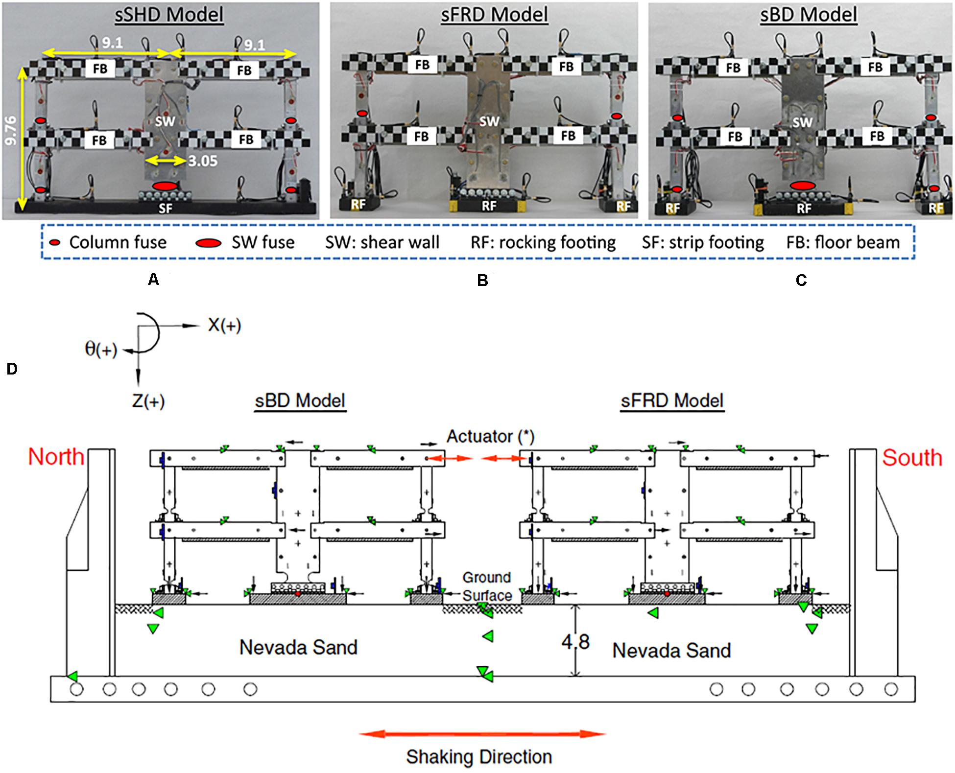
Figure 7. Frame wall-foundation models for testing on the 9-m centrifuge (Liu et al., 2015a): (A) structural hinging dominated SHD model, (B) foundation rocking dominated FRD model, (C) balanced design model BD, and (D) arrangement of models in the soil container for static and dynamic testing on the centrifuge.
A common misconception about rocking foundations was that rocking foundations might increase the demand on the structure. The 9-m centrifuge building models showed that rocking foundations, if properly designed, could absorb much of the ductility demand and hence reduce the ductility demand on structural components. The slow cyclic tests on the model buildings demonstrated that the rocking-dominated systems had ductile and stable responses with very little strength degradation, and better re-centering than hinging-dominated systems. The dynamic earthquake shaking tests confirmed that the ductility demand on the shear wall component of the system decreases and system performance improves when demand is shifted from wall hinging to the rocking foundation. Furthermore, systems with rocking foundations sustained a smaller peak roof acceleration, residual drift, and reduced peak base shear despite the relatively larger peak transient drift demand. Consistent with slow cyclic test results, dissipated hysteretic energy was reasonably distributed amongst superstructure and substructure inelastic components if the capacity of the wall and its foundation are balanced; this finding is illustrated in Figure 8 showing the moment-rotation response in a column fuse (Figure 8A), the moment-rotation of the shear wall foundation, (Figure 8B), and the moment-rotation response of a single column’s spread footing (Figure 8C) during slow cyclic loading on a balanced design model. Dynamic shaking tests were then performed on similar structural models that were densely instrumented, after which inverse analyses techniques were used to back-calculate various moment-rotation responses that could not otherwise have been directly measured. The nature and distribution of plastic yielding was similar between the slow cyclic and dynamic tests, providing confidence in both sets of data. These centrifuge models, with their holistic systems-level details, provided unique experimental data that was the basis for validating the ability of numerical simulation procedures to approximate nonlinearity in the structure and foundation. Numerical simulations demonstrated comparable local and global response to measurements obtained during the experiments, as illustrated by the comparisons of measured and computed moment-rotation responses of the shear wall footings shown in Figure 9.
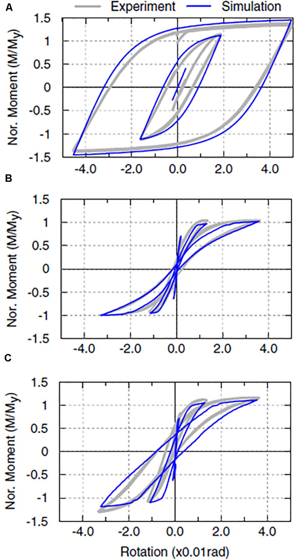
Figure 8. Hysteretic response of inelastic elements in the sFRD model: (A) column fuse at level 2, (B) shear wall rocking footing, and (C) column rocking footing (Permission from Liu et al., 2015a with permission from ASCE).

Figure 9. Hysteretic rocking response of shear wall footings during shaking with two for two input motions: measured response based on inverse analyses of sensor data (gray lines) and simulated responses from finite element analyses (blue lines) (Reproduced from Liu et al., 2015b with permission from ASCE).
Centrifuge model experiments like those described above, along with centrifuge and shaking table tests performed by others for a broad range of soil conditions and structural systems, provided the basis for rapid broader impact through development and implementation of design procedures for practice. In this regard, projects on rocking foundations using the 1-g shaking table at the UC San Diego NHERI facility and the 9-m centrifuge at UC Davis are illustrative of their complementary roles (Allmond and Kutter, 2014a, b; Antonellis et al., 2015). The 1 g shaking table tests examined rocking responses for two single-degree-of-freedom structures supported on 1.5-m by 1.5-m square spread footings in the same experiment; the large size of the footings enable use of local contact sensors to examine the footing-soil-interface interaction at a high level of detail. The companion tests on the 9-m centrifuge enable simulation of six single-degree-of-freedom structures supported on 7.5-m by 7.5-m square (prototype scale) footings in the same experiment: the enhanced g-field in the centrifuge enabled simulating rocking structures at greater load and stress levels, and to include a greater number of structure/footing configurations at significantly lower cost. This is just one example of how the combination of the 1-m centrifuge, 9-m centrifuge, and large-scale 1-g shaking table facilities in the NHERI network provide flexibility to tackle complex problems across an appropriate and complementary range of scales, depending on the fundamental scientific and engineering issues being explored.
Technology transfer on rocking foundation research was facilitated by the formation of a Technology Transfer Team of practitioners with geotechnical and structural expertise related to buildings and bridges. This group of nominally six people worked over a period of several years, and contributed to guidance for building code provisions that eventually allowed designers to use foundation rocking as an effective mechanism contributing to the seismic performance of buildings per ASCE/SEI 41-17 (2017). The findings advanced the state of practice for design and for numerical modeling of soil-structure systems. The collaboration between students, faculty, and leading practitioners from industry provided a uniquely broad experience for all of the participants – especially the students.
Microbially induced calcite precipitation is a bio-mediation ground improvement method that uses soil microorganisms to induce calcite precipitation within sandy soils (Figure 10). MICP bio-cementation can significantly increase the resistance of liquefaction triggering of granular soils through particle bonding (cementation), increased particle angularity, and increased density, which results in stronger dilative tendencies (DeJong et al., 2010; Montoya and DeJong, 2015; Feng and Montoya, 2016). MICP bio-cementation has the potential to be a tunable, noninvasive method for treating liquefiable soils around existing infrastructure where other invasive ground improvement methods are not feasible. Challenges for advancing this technique include optimizing use of native microorganisms, tuning the bio-cementation process, collecting and processing byproducts, upscaling to field scale, establishing in-situ quality control measures, and developing the fundamental knowledge base on material behaviors required for engineering design (DeJong et al., 2013). The NSF-sponsored Center for Bio-mediated and Bio-inspired Geotechnics (CBBG) is working to advance MICP ground improvement from the bench scale to field scale in partnership with industry collaborators.
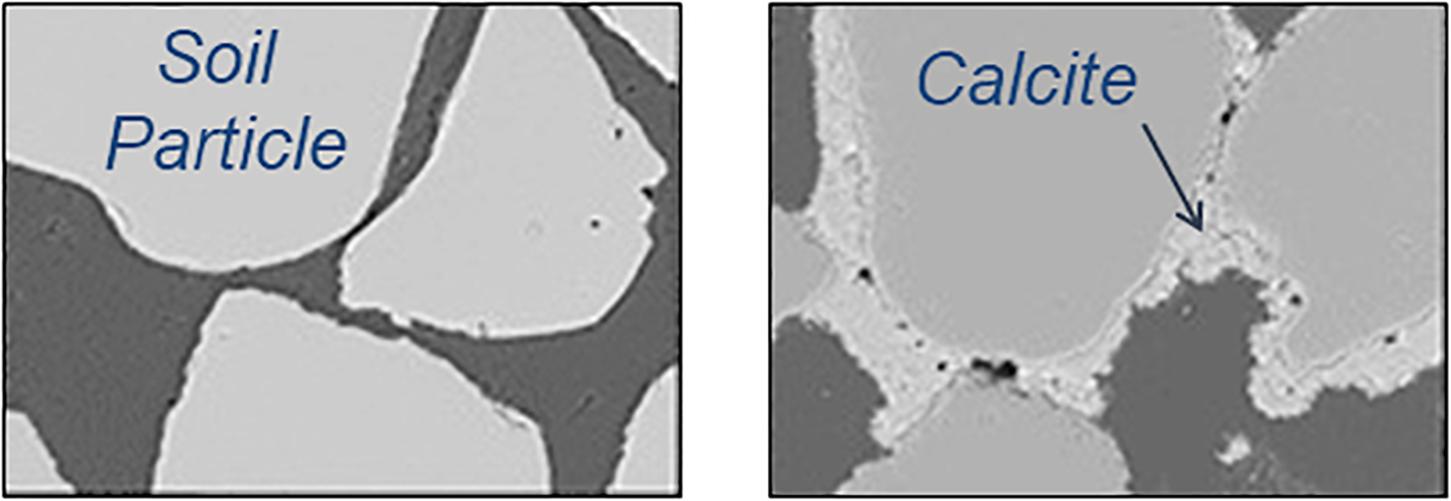
Figure 10. Images of sand particles before and after MICP treatment (Reproduced from DeJong et al., 2006 with permission from ASCE).
The CBBG selected the NHERI centrifuge facilities at UC Davis for testbed development of MICP bio-cementation, as well as other bio-mediated and bio-inspired processes, because it offered the flexibility for physical modeling at small (Figure 11A) and large (Figure 11B) scales using the 1-m and 9-m radius centrifuges, respectively. The 1-m radius centrifuge, with its smaller models, provides for high throughput of relatively simple tests that enable rapid and efficient exploration of model preparation techniques, in-flight characterization techniques (shear wave velocity Vs and cone penetration testing), and degradation of the improved soil in a relatively simple model when subjected to changing static and dynamic loading. In a recent CBBG study (Darby et al., 2019), models were prepared with loose saturated sands having no, light, moderate, and heavy levels of biocementation, and then subjected to multiple shaking events with peak base accelerations of 0.02 to 0.55 g. Arrays of accelerometers and pore pressure transducers were used to compute cyclic stress ratios, shear strains, and excess pore pressure generation. A mini-cone penetrometer was pushed at select times during each test to evaluate the ability of the cone to capture the effects of initial cementation and cementation degradation induced by shaking. Horizontal shear wave (Vs) measurements (which give small-strain shear moduli) were obtained prior to each cone push and shaking event using two arrays of bender element (BE) pairs placed with depth. The increase in cone penetration resistance and Vs with the calcium carbonate content produced by the MICP process are shown in Figures 12A,B, respectively. Inverse analyses of dynamic response using the instrumentation arrays were used to define cyclic stress ratios (CSRs) imposed on the soil during shaking, up through the triggering of significant shear strains. The inverse-computed CSRs are plotted versus cone penetration and Vs values in Figure 13, along with common correlations for estimating liquefaction and non-liquefaction triggering conditions in non-cemented sands (Kayen et al., 2013; Boulanger and Idriss, 2015). Additional details on these tests and their interpretations are provided in Darby et al. (2019). The key observations are that the results of these types of tests, starting on the 1-centrifuge and now moving to the 9-m centrifuge (with its better resolution on details), provide a unique means for evaluating how industry-standard liquefaction triggering procedures may be adapted to MICP treated sands.
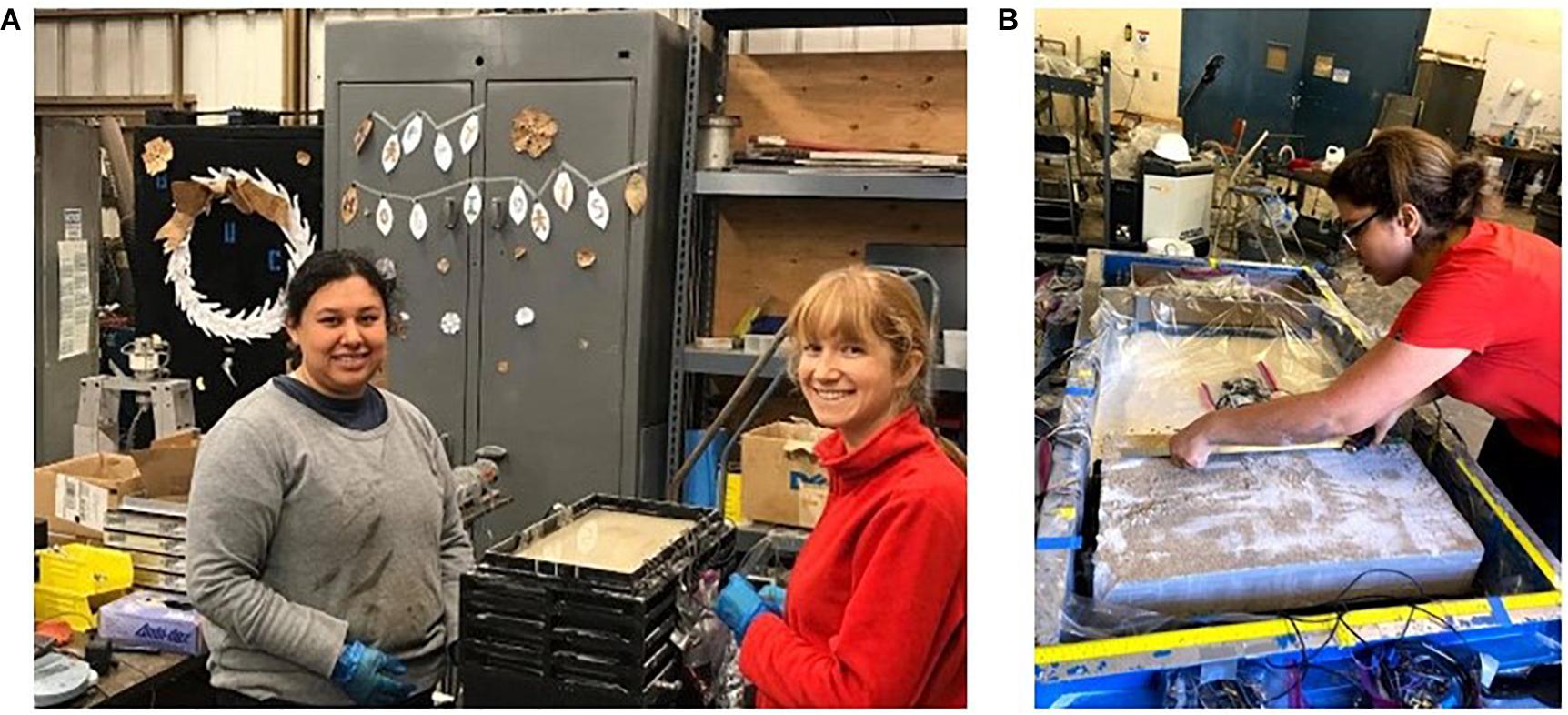
Figure 11. Bio-mediation of sand models for centrifuge testing: (A) component level model for testing on the 1-m radius centrifuge, and (B) system level model for testing on the 9-m radius centrifuge.
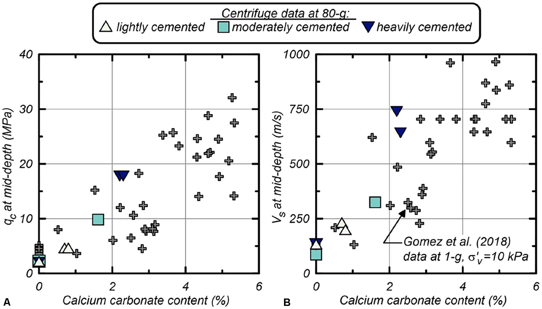
Figure 12. (A) Cone penetration resistance and (B) shear wave velocity at mid-depth in a model on the 1-m radius centrifuge versus the calcium carbonate content produced by MICP treatment (Permission from Darby et al., 2019 with permission from ASCE).
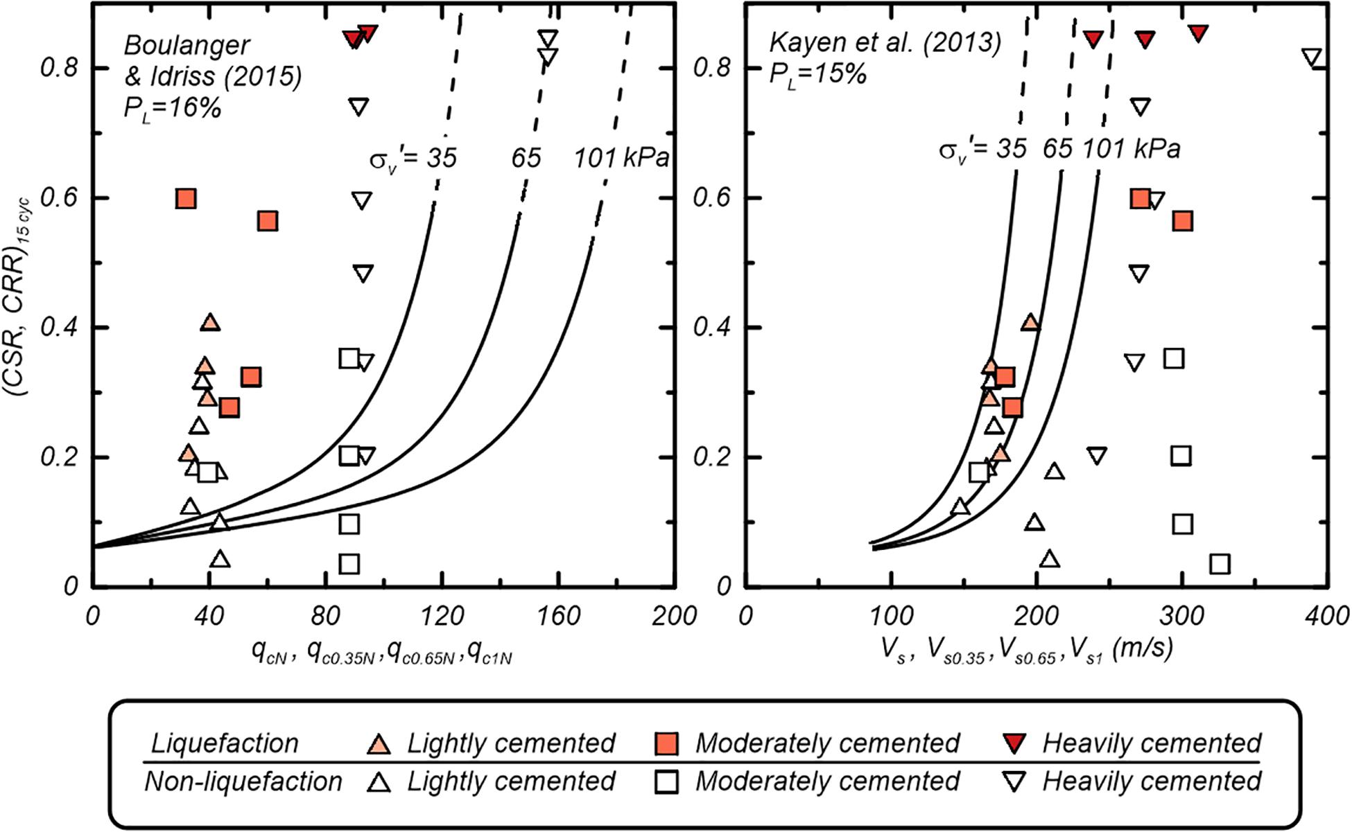
Figure 13. Equivalent uniform cyclic stress ratios versus cone penetration resistance and shear wave velocity in a saturated sand model subject to dynamic loading on the 1-m radius centrifuge, along with case-history based liquefaction triggering correlations used in practice (Reproduced from Darby et al., 2019 with permission from ASCE).
In a test recently performed and not yet published, the 9-m radius centrifuge was used to perform a more holistic investigation of system-level performance. The test configuration included multiple surface foundation structures founded on a soil profile with spatially varying relative density, including soil layers susceptible to liquefaction at different depths, and multiple MICP treatment strategies, including untreated, shallow, and deep treatments (Figure 14). Arrays of accelerometers and pore pressure transducers within the soil, along with displacement and acceleration measurements on the structures, were used to capture the soil and structure responses. Multiple shaking events with peak base accelerations ranging from 0.03 to 0.5 g were applied. Cone penetration resistance, qc, and Vs testing were used to characterize the initial model conditions as well as the change in conditions (i.e., cementation degradation, soil densification) through the course of shaking. Surface settlement measurements and observations (Figure 15) provided an evaluation of the degree to which MICP treatment applied to limited depths affected the dynamic site response, triggering of liquefaction at different depths, and surface expression of that liquefaction. A key advantage of these types of large model tests, with multiple variations in conditions across the same container, are that the comparisons of performance are better constrained by the fact the soils throughout the container were prepared by the same researcher at one time and the same shaking motions were imposed throughout the model.
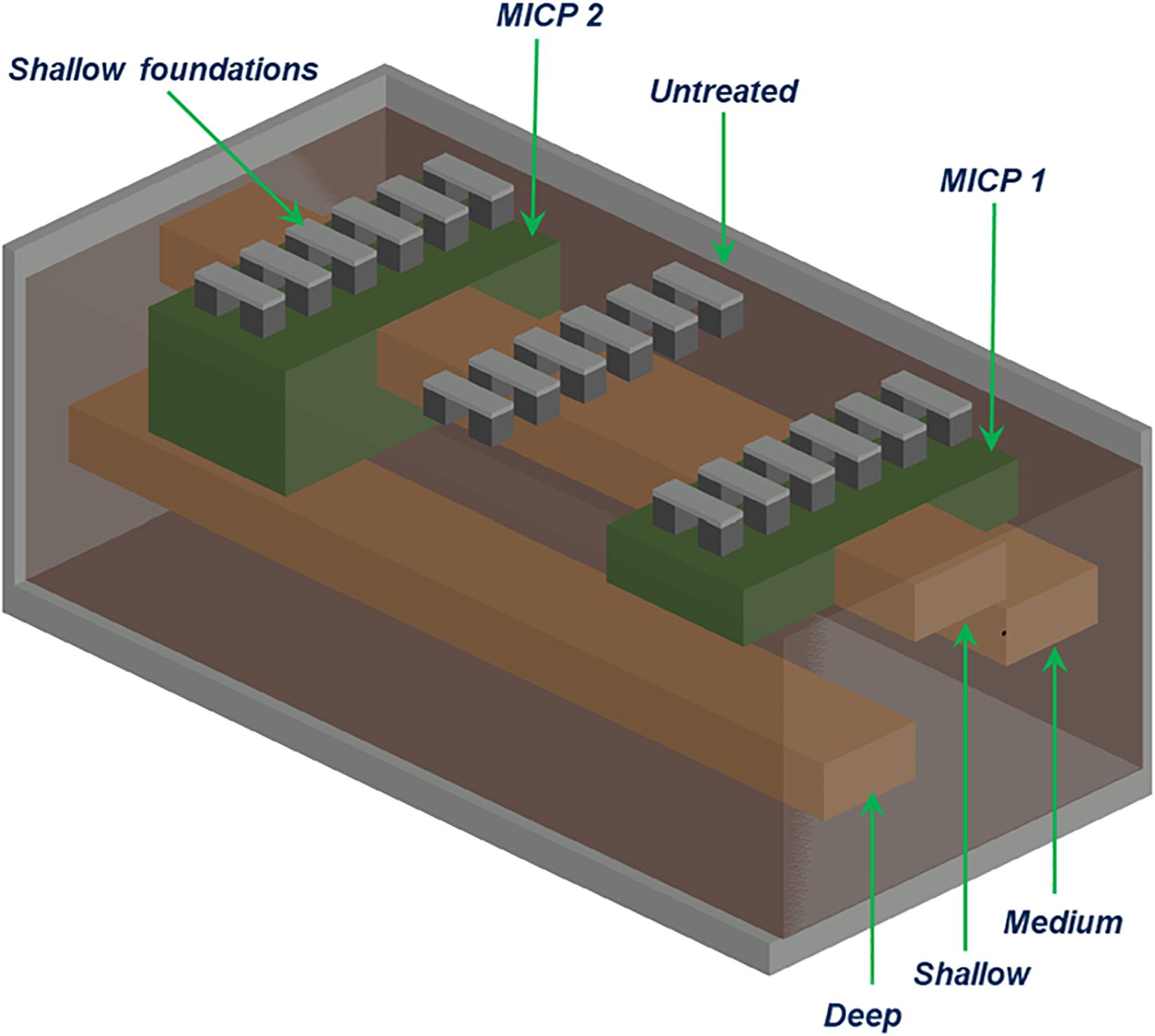
Figure 14. Configuration of a centrifuge model for the 9-m centrifuge; multiple shallow foundations arranged over areas that have no, shallow, and deep MICP treatments (labeled as Untreated, MICP 1 and MICP 2) with loose layers of liquefiable sand at shallow, medium, and deep intervals.
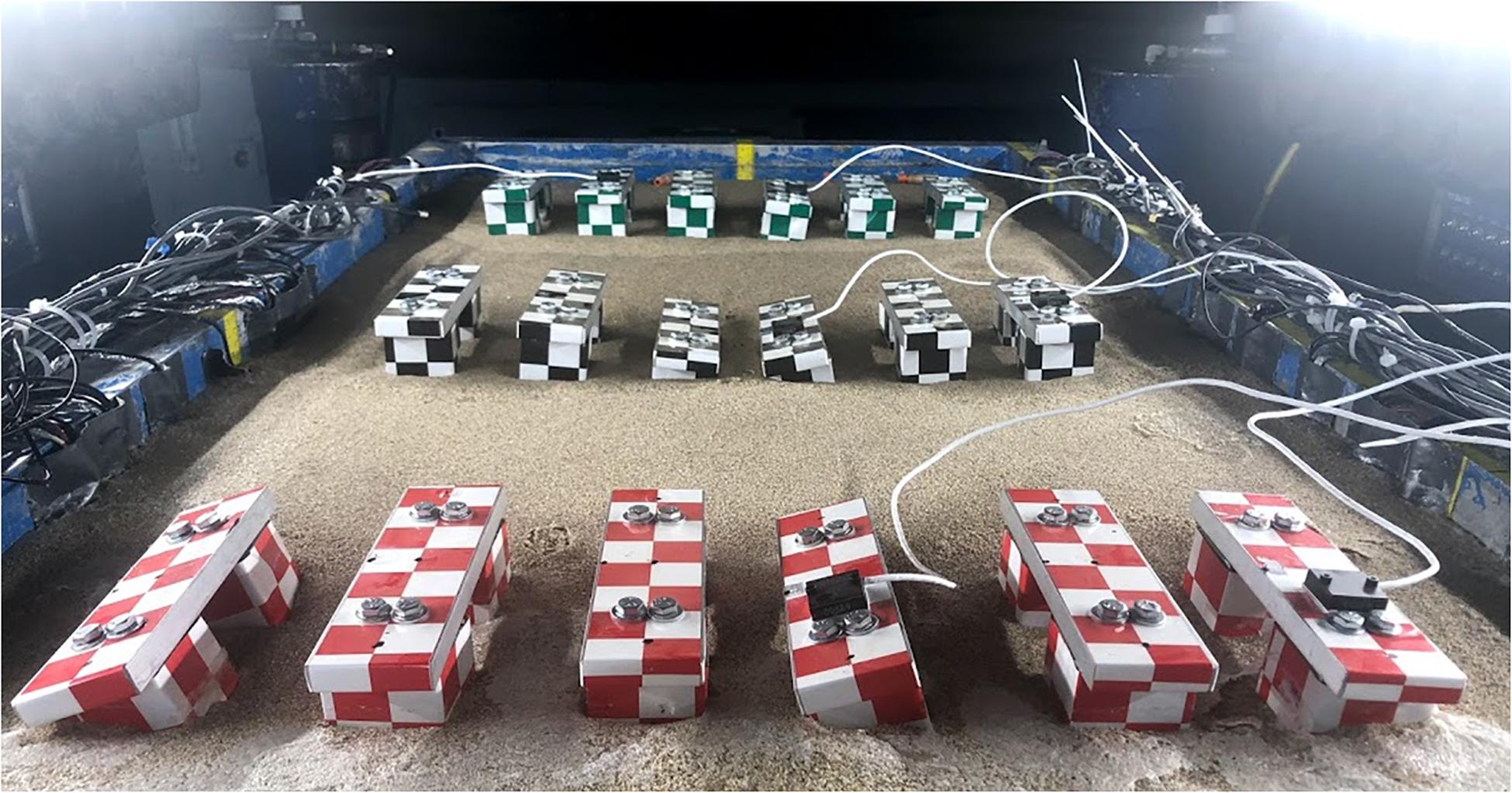
Figure 15. Post-shaking photograph showing the variation of foundation settlements and tilting across the untreated, MICP 1 and MICP 2 treatment zones with liquefiable layers at shallow, medium, and deep intervals.
The 9-m and 1-m centrifuge models provided the first insights and essential data on fundamental behaviors of MICP treated sands at a systems level. The 1-m centrifuge tests first demonstrated how changes in liquefaction resistance, Vs, and qc for loose saturated sands treated by light, moderate or heavy levels of bio-cementation, as well as the degradation of cementation, occurs with increasing shaking intensity. Cone penetration resistances at mid-depth increased from 2 to 5, 2 to 10, and 2 to 18 MPa in lightly, moderately, and heavily cemented models, respectively. Vs at mid-depth increased from 140 to 200, 140 to 325, and 140 to 660 m/s in lightly, moderately, and heavily cemented models at 80 g, respectively. Cone penetration resistances and Vs after initial liquefaction decreased significantly in moderately and heavily cemented models, decreased slightly in lightly cemented models, and increased slightly in uncemented models. Cemented models required stronger peak base accelerations (PBAs) and cyclic stress ratios (CSRs) to trigger liquefaction compared to the uncemented model prepared to a similar relative density, even after initial liquefaction in a prior shaking event. The 9-m centrifuge tests are still being analyzed, but data analysis to date have shown changes in CPT qc and Vs that are consistent with the 1 m centrifuge, confirming the scalability of model testing. The performance of the MICP improved zones within a large volume of untreated soil provided new insights with respect to the rate of cementation degradation, how MICP improved zones affected dynamic response, and how MICP improved zones can effectively reduce ground surface distortions due to triggering of liquefaction at different depths. The net practical benefit of MICP treatments was reduced absolute and differential settlement of surface foundations. On average, the absolute settlement of surface foundations due to liquefaction of the underlying layers was reduced by more than 80%, and the differential settlement was reduced by a similar level.
MICP and other bio-mediated remediation methods for liquefiable sands are emerging from being novel, creative, blue-skies ideas to being efficient, sustainable technologies that will likely be implemented at the field scale in the next 5 years. The NSF-sponsored CBBG has enabled the rapid maturation of these technologies by facilitating teams working on the fundamental aspects of the biogeochemical treatment process, evaluating how engineering properties change at the element/constitutive level, and developing how the technology can be up-scaled for field implementation. The NHERI CGM facility provides the critical additional capability of performing simple and complex system model analyses prior to when the technology is ready for field implementation. This has enabled re-evaluation of industry standard liquefaction triggering curves for cemented soils, development of CPT qc and seismic Vs QA/QC monitoring techniques and target values, and quantified the level of improvement that may be able to be achieved with MICP improvement is applied in both free-field conditions and beneath embankments.
The research performed at the NHERI centrifuge facility often have direct broader impacts, such as those described above. The CGM, through its participation as a NHERI facility, pursues broader impacts collectively in addition to the scientific advances discussed in the previous sections. Through its shared use, the facility hosts a range of visiting domestic and international researchers, industry collaborators, graduate students, undergraduate students, visitor tours, and K-12 classes, with the total number of visitors averaging a few hundred each year. Broader impacts include strengthening academic-industry partnerships to bridge science and practice, contributing to the development of codes and guidance documents, producing and sharing large datasets, training practitioners, and educating students through centrifuge activities. As education is critical to the missions of the NHERI centrifuge facility and CBBG, select activities are described in this section.
Students in traditional engineering curriculums often have a simplified concept of what a model is or can do, and have limited ability to use model-based reasoning (Carberry and McKenna, 2014). Wartman (2006) identified four benefits associated with students learning geotechnical engineering through physical modeling: (1) visualization of complex, nonlinear geotechnical mechanisms and phenomena otherwise difficult to visualize; (2) development of an intuition and physical sense for the fundamental mechanisms that govern the behavior of these systems; (3) observation of failure mechanisms not seen in traditional geotechnical engineering courses, which often focus on element testing; and (4) assessment of the deviation between predicted and actual performance in geotechnical systems.
Through centrifuge modeling, students develop an appreciation of the ability of both physical and numerical models and of model-based reasoning. Student develop professional skills and experience attitudinal shifts as they develop their technical skills (e.g., signal processing, electrical, and mechanical skills). The coordination of their experiments requires strong communication and project management skills, especially in an environment where timelines frequently change due to unexpected circumstances. The physical modeling experience teaches students that engineering projects and the design process are nonlinear and requires they develop adaptive, growth mindsets that allow them to learn from adversity. Dweck (2007) defines a growth mindset as when individuals believe their talents can be developed through hard work, good strategies, and seeking input from others and view failure as a stepping stone to improvement. Successful student centrifuge modelers have or shift to a growth mindset with respect to their modeling skills and knowledge. The process requires students think critically about why a failure occurred and how to learn from it and find a solution. Industry partners have noticed the benefits with a one stating that they “love hiring centrifuge modelers because they already know how to solve problems.”
Individuals use mental structures, or schemas, to organize knowledge and guide cognitive processes and behavior. Vygotsky’s Social Development Theory notes that our specific mental structures and processes can be related to interactions with others around us (Woolfolk, 2013). The theory notes that learning only occurs when you are teaching at a level in which individuals can accommodate the new knowledge or cognitive skills by adapting their current mental structures. Specifically, the Zone of Proximal Development (ZPD) is as the area between a person’s current development level as determined by independent problem solving and the level they could achieve with guidance and collaboration of more capable members of society. The UC Davis geotechnical group’s development of a Ladder Mentoring Model (Bronner et al., 2018) for training graduate students in technical knowledge and skills, professional skills, and educational outreach aligns with Vygotsky’s ZPD. Individuals starting at the NHERI centrifuge facility work with students with a few years of experience to learn new skills. More experienced staff and faculty provide more direct mentoring to those more experienced students (i.e., those who are one rung up on the ladder). This approach to mentoring graduate students in academic environments enriches graduate student development while minimizing additional demands on center personnel.
The educational thrust described here depends on the technical expertise of the geotechnical graduate students and faculty, educational expertise of a CBBG faculty member focused on engineering education, and expertise and support of NHERI personnel in maintaining the equipment and providing a facility for on-campus outreach activities. By strategically leveraging their resources (funding, equipment, space, time, and expertise), the NHERI centrifuge facility and the CBBG are able to implement sustainable outreach and mentoring programs with the mission of educating future geotechnical engineers and broadening participation from underrepresented groups in engineering.
The validation of advanced computational models persists as an overarching challenge in hazards engineering due to the variety of multi-scale, multi-physics, coupled nonlinear interactions that come to the forefront in different realizations of natural, extreme hazards. The 9-m centrifuge enables validation of complex mechanisms through physically large and holistic experiments that support inverse analyses of data from dense instrumentation arrays. The 9-m and 1-m centrifuges together enable validation from component to holistic levels of system complexity. The three research examples presented above illustrate how densely instrumented models with inverse analysis techniques can provide multiple levels of data for validating computational models, from local to global features of response. Validation against measurements of complex local mechanisms provides a higher-resolution evaluation of computation models than is possible with conventional tests and can help identify computational modeling limitations that affect simulation accuracy and generalization at a global scale.
The 9-m and 1-m centrifuges also provide unique opportunities for developing and validating engineering procedures for determining, for a range of challenging soil types, the characterizing properties required for advanced computational models (Bray et al., 2017). Determining soil properties for heterogeneous natural deposits or constructed fills across the scale of civil infrastructure systems usually involves a program of in-situ testing (destructive or nondestructive) and/or laboratory testing of field samples as well as significant engineering judgment in interpolation and interpretation. All currently available in-situ tests, sampling tools, and laboratory tests have known limitations in certain types of soils. Worse yet, there are a broad range of soil types for which no reliable in-situ test or sampling procedure has been developed, which makes the estimation of properties a dominant source of uncertainty in the application of advanced computational models. Examples of challenging soils include sensitive clays and silts (e.g., instabilities due to strain softening), gravelly and cobbly soils (e.g., particle size effects for in-situ tests and loading responses), carbonate soils (e.g., highly crushable), flyash from coal combustion (e.g., crushable and chemically reactive), intermediate soils (e.g., interpretation of in-situ test data in clayey sands to sandy silts), and finely inter-bedded sands and fine-grained soils (e.g., effect of inter-bedding on composite response, and lack of resolution in in-situ test data in thin layers).
The paucity of applicable physical data or case histories for many soil types means that their expected behaviors under generalized loading are poorly understood and the procedures for estimating their properties lack appropriate validation (Bray et al., 2017). Centrifuges provide opportunities to obtain inflight characterization tests (e.g., vane shear, T-bar, CPT, Vs, Vp, and samples for lab testing) and system performance data on the same specimen. The 9-m centrifuge offers the greatest capability for performing these characterization tests in models with realistically holistic levels of system complexity (including geologic complexity, such as inter-bedded sand and silt deposits) and minimizing scale effects (e.g., distorted ratio of penetrometer size to particle or interlayer size). Smaller centrifuges could contribute as well, but their smaller sizes limit model complexity and increases scale effects for some soils and characterization tests. Testing at 1-g in soil boxes can also contribute, but even the largest available 1-g soil boxes have significant limits on model complexity and achievable overburden stresses. Combinations of experiments using the NHERI centrifuge facilities (UC Davis), mobile field dynamic shakers (UT Austin), and large 1-g soil box (UCSD) can provide flexibility and potential synergy for enabling progress across many of the above challenges.
There are numerous other opportunities for technical breakthroughs on issues affecting specific infrastructure systems under loadings from earthquakes, waves, wind, and storms. Examples include the effects of ground deformations or erosion on underground pipelines, effects of tsunamis or storm surge on levees and foundations (e.g., Exton et al., 2018), effects of breaking waves on seashore stability (e.g., Takahashi et al., 2019), effects of storms and earthquakes on foundation systems for near-shore and offshore wind turbines (e.g., Zheng et al., 2019), and development of innovative, low-cost ground improvements for residential homes or levees where society requires a finer balance between costs and performance (e.g., Ishii et al., 2017).
The effective use of centrifuge modeling for geotechnical research requires awareness of several limitations inherent to physical modeling of natural soils as well as the centrifuge environment. The vast majority of physical models, using a centrifuge or shaking table, are constructed using reconstituted soils, which means that numerous environmental factors known to have strong effects on soil properties in the field (e.g., depositional process, over-consolidation, prior seismic loading, age, cementation, pore water chemistry, or thixotropy) are not represented. The large majority of physical models focus on idealized soil profiles with uniform properties within individual soil layers, which means that the influence of stratigraphic complexity and spatial variability remain under-studied experimentally. Centrifuge models are often unable to accurately reproduce complex construction processes, such that certain aspects may be inadequately reflected in the observed responses (e.g., increases in lateral stresses or densification due to vibro-replacement or vibro-installation of piles, drains, and other reinforcing elements), or complex structural systems (e.g., reinforced concrete). Different physical processes (e.g., dynamic shaking and pore pressure diffusion), follow different scaling laws; if these different processes are concurrent and coupled, compromises or special adjustments (e.g., scaling pore fluid viscosity) are required. Model containers impose boundary constraints that may inhibit certain phenomena (e.g., lateral deformations, radiation damping), which means that the selection of the model container requires foresight on the likely responses and interpretations, and that model containers generally need to be included in numerical simulation models. These and other limitations, such as those previously noted regarding scaling limitations with smaller centrifuge models, are generally well-recognized (e.g., Taylor, 1995) and in many cases, represent opportunities for future researchers to overcome.
A combination of NHERI facilities could be particularly effective for addressing some of these problems and more; e.g., the performance of near-shore wind turbines could be examined using model tests at the wind facilities to understand their dynamic responses, model tests at the centrifuge facilities to understand the performance of different foundation systems, and the mobile shakers to characterize the response characteristics of turbines in the field. These and other pressing research needs offer opportunities for partnerships between industry, academia, and public agencies utilizing the centrifuge facilities in combination with other NHERI facilities (wind, tsunami, mobile shaker, 1-g shake table, and RAPID) to contribute to safer and better-managed infrastructure systems.
Enhanced gravity testing also has the potential for increased utilization in scientific disciplines other than geotechnical and hazards engineering, as evidenced by various applications described in the literature. Centrifuge modeling has been used to study a range of geoenvironmental problems, from contaminant transport (Culligan-Hensley and Savvidou, 1995) to site remediation strategies (Marulanda et al., 2000); a number of geologic processes, including intrusions (Dixon and Simpson, 1987), faulting (Koyi and Skelton, 2001), and ice mechanics (Langhorne et al., 1999; Guerin et al., 2016); a number of manufacturing processes, including welding (Aidun and Martin, 1998), casting (Fukui, 1991; Zhang et al., 2018), and powders (Thomas and Beaudoin, 2015); and processes related to gasses and fires (Most et al., 1996). The “Spin your thesis” program by the European Space Agency3 encourages a wide breadth of potential applications by enabling student researchers to perform research on self-selected topics, with many related to fluids and biological processes, on a centrifuge with centrifugal accelerations up to 20 g.
The NHERI facility at UC Davis provides the national research community with open access to 9-m and 1-m radius geotechnical centrifuges, offering unique and versatile modeling capabilities for advancing methods to predict and improve the performance of soil and soil-structure systems affected by earthquake, wave, wind, and storm surge loadings. Three research projects related to seismic hazards – liquefaction effects on a submerged subway tunnel, rocking of shallow foundations, and remediation of liquefaction by MICP – were used to illustrate the facility’s capabilities and the complementary roles of the 9-m and 1-m centrifuges. The 9-m centrifuge models with holistic levels of complexity are particularly effective for the building of basic science knowledge and the validation of advanced computational models from the component to the holistic system level. The NHERI centrifuge facility has helped strengthen academic-industry partnerships to bridge science and practice, contributed to the development of codes and guidance documents, produced and shared large datasets, trained practitioners, and provided uniquely broad educational experiences to a diverse group of researchers.
Some future research opportunities using the NHERI centrifuge facilities were discussed, although the scale and breadth of multi-physics, systems-level challenges that society faces are greater than could be covered in this paper. Opportunities for enhanced gravity testing in technical disciplines other than geotechnical and hazards engineering were briefly discussed to illustrate opportunities for any user to leverage this national shared use facility. The authors expect the coming decades will see continued advances in centrifuge modeling technology and a broadening of its utilization.
Written informed consent was obtained from the individuals for the publication of any potentially identifiable images or data included in this article.
RB and DW outlined the manuscript. BK, JD, CB, DW, and RB contributed drafts for sections of the manuscript. All authors contributed to manuscript revisions, read, and approved the submitted manuscript.
The National Science Foundation (NSF) has supported the development and operation of the geotechnical centrifuge facilities at UC Davis through the Network for Earthquake Engineering Simulation (NEES) program, award numbers CMS-0086566, CMMI-0402490, and CMMI-0927178, and the Natural Hazards Engineering Research Infrastructure (NHERI) program, award number CMMI 1520581. Additional support for facility developed was provided by Obayashi Corporation, Caltrans, and the University of California at Davis. The three research examples presented herein were supported by Fugro West with funds originating from BART, the NSF under cooperative agreement No. EEC-1449501, and the NSF under award number CMMI-0936503, respectively. Any opinions, findings, and conclusions or recommendations expressed in this material are those of the author(s) and do not necessarily reflect those of the above organizations.
The authors declare that the research was conducted in the absence of any commercial or financial relationships that could be construed as a potential conflict of interest.
Contributions to facility developments were provided by past CGM Directors Jim Cheney and I. M. Idriss and all former and current CGM staff. The authors thank Kate Darby, Gabby Hernandez, Atefeh Zamani, and Peng Xiao for the figures and data presented in the MICP treatment example.
Aidun, D. K., and Martin, S. A. (1998). Penetration in spot GTA welds during centrifugation. J. Mater. Eng. Perform. 7, 597–600. doi: 10.1361/105994998770347431
Alameddine, F., and Imbsen, R. A. (2002). “Rocking of bridge piers under earthquake loading,” in Proceedings of the Third National Seismic Conference and Workshop on Bridges and Highways: Advances in Engineering and Technology for the Seismic Safety of Bridges in the New Millennium, eds R. Nimis and M. Bruneau (New York: University of SUNY Buffalo), 624.
Allmond, J. D., and Kutter, B. L. (2014a). Design considerations for rocking foundations on unattached piles. J. Geotechn. Geoenviron. Eng. 140:04014058. doi: 10.1061/(ASCE)GT.1943-5606.0001162
Allmond, J. D., and Kutter, B. L. (2014b). “Fluid effects on rocking foundations in difficult soil,” in Proceedings of the Tenth U.S. National Conference on Earthquake Engineering, Oakland, CA.
Antonellis, G., Gavras, A. G., Panagiotou, M., Kutter, B. L., Guerrini, G., Sander, A. C., et al. (2015). Shake table test of large-scale bridge columns supported on rocking shallow foundations. J. Geotechn. Geoenviron. Eng. 141:04015009. doi: 10.1061/(ASCE)GT.1943-5606.0001284
Beaty, M., and Byrne, P. M. (1998). “An effective stress model for predicting liquefaction behavior of sand,” in Proceedings of a Specialty Conference, Geotechnical Earthquake Engineering and Soil Dynamics, Seattle
Boulanger, R. W., and Idriss, I. M. (2015). CPT-based liquefaction triggering procedure. J. Geotechn. Geoenviron. Eng. 142:04015065. doi: 10.1061/(ASCE)GT.1943-5606.0001388
Bray, J. D., Boulanger, R. W., Cubrinovski, M., Tokimatsu, K., Kramer, S. L., O’Rourke, T., et al. (2017). U.S.-New Zealand-Japan International Workshop, Liquefaction-Induced Ground Movement Effects. PEER Report 2017/02. Berkeley, CA: University of California.
Bronner, C. E., Wilson, D. W., Ziotopoulou, K., Darby, K. M., Sturm, A., Raymond, A. J., et al. (2018). “An example of effective mentoring for research centers,” in Proceedings of the Physical Modelling in Geotechnics, eds A. S. McNamara, R. Divall, N. Goodey, S. Taylor, and J. Panchal (London: Taylor and Francis Group).
Carberry, A. R., and McKenna, A. F. (2014). Exploring student conceptions of modeling and modeling uses in engineering design: student modeling in engineering design. J. Eng. Educ. 103, 77–91. doi: 10.1002/jee.20033
Chang, D., Travasarou, T., and Chacko, J. M. (2008). “Numerical evaluation of liquefaction-induced uplift for an immersed tunnel,” in Proceedings of the 14th World Conference on Earthquake Engineering (WCEE), Beijing.
Chou, J. C., Kutter, B. L., Travasarou, T., and Chacko, J. M. (2011). Centrifuge modeling of seismically induced uplift for the BART Transbay tube. J. Geotechn. Geoenviron. Eng. 137, 754–765. doi: 10.1061/(ASCE)GT.1943-5606.0000489
Comartin, C. D., Niewiaroski, R. W., Freeman, S., and Turner, F. M. (2000). Seismic evaluation and retrofit of concrete buildings: a practical overview of the ATC-40 document. Earthq. Spectr. 16, 241–262.
Craig, W. H., Vinogradov, V. V., Frolovsky, Y. K., and Zaytsev, A. A. (2015). Pioneers of centrifuge modeling. Intern. J. Phys. Model. Geotech. 15, 3–18. doi: 10.1680/ijpmg.14.00018
Culligan-Hensley, P. J., and Savvidou, C. (1995). “Environmental geomechanics and transport processes,” in Chapter 8 in Geotechnical Centrifuge Technology Blackie Academic and Professional, ed. R. L. Taylor (London: Chapman & Hall).
Darby, K. M., Hernandez, G. L., DeJong, J. T., Boulanger, R. W., Wilson, D. W., and Gomez, M. G. (2019). Centrifuge model testing of liquefaction mitigation via microbially induced calcite precipitation. J. Geotechn. Geoenviron. Eng. 145:10. doi: 10.1061/(ASCE)GT.1943-5606.0002122
DeJong, J. T., Fritzges, M. B., and Nusslein, K. (2006). Microbially induced cementation to control sand response to undrained shear. J. Geotechn. Geoenviron. Eng. 132:1381. doi: 10.1061/(ASCE)1090-02412006132:111381
DeJong, J. T., Mortensen, B. M., Martinez, B. C., and Nelson, D. C. (2010). Bio-mediated soil improvement. Ecol. Eng. 36, 197–210. doi: 10.1016/j.ecoleng.2008.12.029
DeJong, J. T., Soga, K. S., Kavazanjian, E., Burns, S., van Paassen, L., Al Qabany, A., et al. (2013). Biogeochemical processes and geotechnical applications: progress, opportunities, and challenges. Geotechnique 63, 287–301.
Dixon, J. M., and Simpson, D. G. (1987). Centrifuge modeling of laccolith intrusion. J. Struct. Geol. 9, 87–103. doi: 10.1016/0191-8141(87)90046-0
Elgamal, A., Yang, Z., and Parra, E. (2002). Computational modeling of cyclic mobility and post-liquefaction site response. Soil Dyn. Earthq. Eng. 22, 259–271. doi: 10.1016/s0267-7261(02)00022-2
Exton, M. C., Harry, S., Mason, H. B., Yeh, H., and Kutter, B. L. (2018). “Novel experimental device to simulate tsunami loading in a geotechnical centrifuge. Physical modelling in geotechnics,” in Proceedings of the 9th International Conference on Physical Modelling in Geotechnics (ICPMG 2018), London.
Feng, K., and Montoya, B. M. (2016). Influence of confinement and cementation level on the behavior of microbial-induced calcite precipitated sands under monotonic drained loading. J. Geotechn. Geoenviron. Eng. 142:1379. doi: 10.1061/(ASCE)GT.1943-5606.0001379
Fukui, Y. (1991). Fundamental investigation of functionally gradient material manufacturing system using centrifugal force. JSME Intern. J. 34, 144–148. doi: 10.1299/jsmec1988.34.144
Gajan, S., and Kutter, B. L. (2008). Capacity, settlement, and energy dissipation of rocking shallow foundations. J. Geotechn. Geoenviron. Eng. 134, 1129–1141. doi: 10.1061/(asce)1090-0241(2008)134:8(1129)
Garnier, J., Gaudin, C., Springman, S. M., Culligan, P. J., Goodings, D., Konig, D., et al. (2007). Catalogue of scaling laws and similitude questions in geotechnical centrifuge modelling. Intern. J. Phys. Model. Geotechn. 7, 1–23. doi: 10.1680/ijpmg.2007.070301
Guerin, F., Laforte, C., Farinas, M.-I., and Perron, J. (2016). Analytical model based on experimental data of centrifuge ice adhesion tests with different substrates. Cold Reg. Sci. Technol. 121, 93–99. doi: 10.1016/j.coldregions.2015.10.011
Hakhamaneshi, M., and Kutter, B. L. (2016). Effect of footing shape and embedment on the settlement, recentering, and energy dissipation of shallow footings subjected to rocking. J. Geotechn. Geoenviron. Eng. 142:1564. doi: 10.1061/(ASCE)GT.1943-5606.0001564
Hakhamaneshi, M., Kutter, B. L., Moore, M., and Champion, C. (2016). Validation of ASCE 41-13 modeling parameters and acceptance criteria for rocking shallow foundations. Earthq. Spectr. 32, 1121–1140. doi: 10.1193/121914eqs216m
Ishii, I., Towhata, I., Hiradate, R., Tsukuni, S., Uchida, A., Sawada, S., et al. (2017). Design of grid-wall soil improvement to mitigate soil liquefaction damage in residential areas of Urayasu. J. Jpn. Soc. Civil Eng. 5, 27–44. doi: 10.2208/journalofjsce.5.1_27
Itasca Consulting Group Inc (2006). Fast Lagrangian Analysis of Continua (FLAC2D). Version 5.0, (2006b), FLAC3D Version 3.1. Minneapolis, MI: Itasca Consulting Group Inc.
Kayen, R., Moss, R. E. S., Thompson, E. M., Seed, R. B., Cetin, K. O., Der Kiureghian, A., et al. (2013). Shear-wave velocity-based probabilistic and deterministic assessment of seismic soil liquefaction potential. J. Geotechn. Geoenviron. Eng. 139:743. doi: 10.1061/(ASCE)GT.1943-5606.0000743
Koyi, H. A., and Skelton, A. (2001). Centrifuge modelling of the evolution of low-angle detachment faults from high-angle normal faults. J. Struct. Geol. 23, 1179–1185. doi: 10.1016/S0191-8141(00)00185-1
Kutter, B. L., Chou, J. C., and Travasarou, T. (2008). “Centrifuge testing of the seismic performance of a submerged cut-and-cover tunnel in liquefiable soil. Geotechnical Special Publication No. 181,” in Proceedings of the Geotechnical Earthquake Engineering and Soil Dynamics IV, Oakland, CA.
Langhorne, P. J., Stone, K. J. L., and Smith, C. C. (1999). The bearing capacity of saline ice sheets: centrifuge modeling. Can. Geotechn. J. 36, 467–481. doi: 10.1139/t99-014
Liu, W., Hutchinson, T. C., Gavras, A. G., Kutter, B. L., and Hakhamaneshi, M. (2015a). Seismic behavior of frame-wall-rocking foundation systems. I: test program and slow cyclic results. J. Struct. Eng. 141:04015059. doi: 10.1061/(ASCE)ST.1943-541X.0001264
Liu, W., Hutchinson, T. C., Gavras, A. G., Kutter, B. L., and Hakhamaneshi, M. (2015b). Seismic behavior of frame-wall-rocking foundation systems. II: dynamic test phase. J. Struct. Eng. 141:04015060. doi: 10.1061/(ASCE)ST.1943-541X.0001313
Marulanda, C., Culligan, P. J., and Germaine, J. T. (2000). Centrifuge modeling of air sparging - a study of air flow through saturated porous media. J. Hazard. Mater. 72, 179–215. doi: 10.1016/S0304-3894(99)00140-5
Montoya, B. M., and DeJong, J. T. (2015). Stress-strain behavior of sands cemented by microbially induced calcite precipitation. J. Geotechn. Geoenviron. Eng. 141:1302. doi: 10.1061/(ASCE)GT.1943-5606.0001302
Most, J. M., Mandin, P., Chen, J., Joulain, P., Durox, D., and Fernande-Pello, A. C. (1996). Influence of gravity and pressure on pool fire-type diffusion flames. Proc. Combust. Inst. 26, 1311–1317. doi: 10.1016/S0082-0784(96)80349-3
Takahashi, H., Morikawa, Y., and Kashima, H. (2019). Centrifuge modelling of breaking waves and seashore ground. Intern. J. Phys. Model. Geotechn. 19, 115–127. doi: 10.1680/jphmg.17.00037
Tasiopoulou, P., Ziotopoulou, K., Humire, F., Giannakou, A., Chacko, J., and Travasarou, T. (2019). Development and implementation of semiempirical framework for modeling postliquefaction shear deformation accumulation in sands. J. Geotechn. Geoenviron. Eng. 146:04019120. doi: 10.1061/(ASCE)GT.1943-5606.0002179
Taylor, R. N. (1995). Geotechnical Centrifuge Technology. London: Blackie Academic and Professional.
Thomas, M. C., and Beaudoin, S. P. (2015). An enhanced centrifuge-based approach to powder characterization: particle size and Hamaker constant deter- mination. Powder Technol. 286, 412–419. doi: 10.1016/j.powtec.2015.08.010
Wartman, J. (2006). Geotechnical physical modeling for education: learning theory approach. J. Prof. Iss. Eng. Ed. Pr. 132. doi: 10.1061/(ASCE)1052-3928(2006)132:4(288)
Wilson, D. W., and Allmond, J. D. (2014). “Advancing geotechnical earthquake engineering knowledge through centrifuge modeling,” in Proceedings, 8th International Conference on Physical Modeling in Geotechnics, Milton Park.
Wilson, D. W., Boulanger, R. W., Kutter, B. L., and Abghari, A. (1997). “Aspects of dynamic centrifuge testing of soil-pile-superstructure interaction,” in Observation and Modeling in Numerical Analysis and Model Tests in Dynamic Soil-Structure Interaction Problems, ed. T. Nogami Geotechnical Special Publication No. 64, ASCE, 47–63.
Wilson, D. W., Kutter, B. L., and Boulanger, R. W. (2010). “NEES @ UC davis,” in Proceedings of the Seventh International Conference on Physical Modeling in Geotechnics (ICPMG 2010), New York, NY.
Woolfolk, A. (2013). “Chapter 2: Cognitive development,” in Education Psychology (Upper Saddle River, NJ: Pearson).
Zhang, X., Hao, J., Guo, Z., Luo, J., Chen, G., Yang, F., et al. (2018). The improved thermal conductivity of a potting material for high-power fast warm-up cathodes. J. Mater. Eng. Perform. 27, 6701–6708. doi: 10.1007/s11665-018-3760-5
Keywords: centrifuge, physical modeling, geotechnical, inverse analyses, natural hazards
Citation: Boulanger RW, Wilson DW, Kutter BL, DeJong JT and Bronner CE (2020) NHERI Centrifuge Facility: Large-Scale Centrifuge Modeling in Geotechnical Research. Front. Built Environ. 6:121. doi: 10.3389/fbuil.2020.00121
Received: 30 April 2020; Accepted: 06 July 2020;
Published: 22 July 2020.
Edited by:
Carlos Estuardo Ventura, University of British Columbia, CanadaReviewed by:
Ertugrul Taciroglu, University of California, Los Angeles, United StatesCopyright © 2020 Boulanger, Wilson, Kutter, DeJong and Bronner. This is an open-access article distributed under the terms of the Creative Commons Attribution License (CC BY). The use, distribution or reproduction in other forums is permitted, provided the original author(s) and the copyright owner(s) are credited and that the original publication in this journal is cited, in accordance with accepted academic practice. No use, distribution or reproduction is permitted which does not comply with these terms.
*Correspondence: Ross W. Boulanger, cndib3VsYW5nZXJAdWNkYXZpcy5lZHU=
Disclaimer: All claims expressed in this article are solely those of the authors and do not necessarily represent those of their affiliated organizations, or those of the publisher, the editors and the reviewers. Any product that may be evaluated in this article or claim that may be made by its manufacturer is not guaranteed or endorsed by the publisher.
Research integrity at Frontiers
Learn more about the work of our research integrity team to safeguard the quality of each article we publish.