 Christian Kelleter
 Timon Burghardt2
94% of researchers rate our articles as excellent or good
Learn more about the work of our research integrity team to safeguard the quality of each article we publish.
Find out more
ORIGINAL RESEARCH article
Front. Built Environ. , 22 July 2020
Sec. Structural Sensing, Control and Asset Management
Volume 6 - 2020 | https://doi.org/10.3389/fbuil.2020.00091
This article is part of the Research Topic Design and Control of Adaptive Civil Structures View all 13 articles
The rapidly growing world population is a great challenge for the building industry. Due to the impending scarcity of resources, it is not possible to provide the growing mankind with sufficient living and work places and infrastructure with current construction methods. For wide-spanning beams and slabs, the decisive design criteria are mainly determined by deformations rather than stresses, since deflections must be limited. This leads to structural elements, which are not fully utilized. However, if the deformations can be reduced, significant material savings can be achieved. Sensors, actuators, and a control unit enable components subjected to bending to adapt to high but rare loads. This article presents a solution that allows beams to react actively to loads by use of integrated actuators. The newly developed integrated hydraulic actuators allow the structure to react specifically to a wide range of load cases, by adjusting the internal hydraulic pressure. This is a clear advantage in load-bearing systems because there is often no dominant load case. This internal actuation concept is a new approach, as previous adaptive structures either have externally added actuators or are composed of truss structures in which single bars are actuated. In this paper, the concept is explained analytically, simulated with the finite element method and validated experimentally.
The increasing world population, the growing urbanization, and the rising standard of living in large parts of the world confront the construction industry with a great challenge, which cannot be solved with conventional methods (Curbach, 2013; Sobek, 2016). Mineral building materials, especially sand, the main component of concrete, are already becoming scarce in some regions of the world (United Nations Environment Programme, 2014). However, extraction is not decreasing and is twice as high as the natural supply (Milliman and Syvitski, 1992). In addition, the cement production alone accounts for about 10% of the total anthropogenic CO2 emissions and subsequently 6% of the anthropogenic greenhouse gases (Scrivener et al., 2016). The entire construction industry is even responsible for 40% of all greenhouse gas emissions (European Commission, 2019). With concrete being the most widely used building material (Mitchel, 2008), alternative design and construction methods must be developed, especially for concrete structures. Therefore, the following investigations are carried out for the material of concrete.
Passive structures are very often oversized for most of their lifetime, as the loads they are designed for rarely or never occur. To give an example, the snow and wind loads for Germany, which are defined in the European codes, have a statistical probability of occurrence once every 50 years (DIN Deutsches Institut für Normung, 2009). This is an annual exceedance probability of just 2%. Nevertheless, of course, structures have to withstand any occurring load, independently of their frequency of occurrence.
Adaptive structures can react to these rare, but usually high loads and allow structures to be designed with less material and therefore with fewer resources and embodied emissions. By means of a smart interaction between actuators, sensors, and a control unit, adaptive structures can reduce stresses, deformations, and vibrations. First concepts of combining such active components with load-bearing structures into a control loop can be found in Yao (1972). However, the motivation behind it was to extend the limiting height of tall buildings rather than saving building materials. Previous studies on adaptive structures, which were not limited to vibration control, can be divided into two categories.
The first category accounts for truss structures in which individual single bars are actuated (contracted or extended). In Weidner et al. (2018), a large-scale prototype of an adaptive high-rise building is presented, in which the deformations and vibrations of the structure can be reduced by active columns and bracing elements. In another example, displacement control has been used to completely compensate for the deflection of an adaptive truss with electrical linear actuators (Senatore et al., 2018).
Senatore et al. (2019) introduce a new method for the design of minimum energy adaptive structures. Embodied energy in the material and operational energy for control units are minimized through combined optimization of structural sizing and actuator placement. Potential reduction of mass and energy consumption of engineering structures through adaptivity has also been investigated via Life Cycle Analysis applied to an adaptive high-rise building (Schlegl et al., 2019).
The second group of studies employs the principle of adaptivity by installing actuators to the structures externally (Domke et al., 1981; Domke, 1992). This means that the whole structure can be manipulated with few actuators. For example, experimental testing on a small-scale prototype has shown that it is possible to manipulate the deformations of a bridge with only one actuator that rotates one of the bridge's bearings (Teuffel, 2004). Experimental testing on a large-scale prototype, an adaptive shell structure, has shown that a significant reduction of stress can be achieved through a translation of the supports, which are equipped with actuators (Sobek et al., 2013; Neuhäuser, 2014).
Further examples for external actuation are structures with variable prestress devices (Pacheco et al., 2010; Schnellenbach-Held et al., 2014). Here, the level of prestressing is adjusted at the anchorage according to the external load. However, the characteristics of the stresses determined by the curved tendons cannot be changed.
In the presented concept, load-bearing structures and actuators are not separated. Several actuators are integrated into the cross-section of a beam, thus allowing for a section-wise manipulation and therefore specific reactions to a wide range of load cases. The focus in many studies is to adapt the whole load-bearing structure, whereas in this paper, the aim is to manipulate beams as a part of an overall structure.
A look at the built environment reveals that almost every building (whether residential or office) consists of components subjected to bending. These are mostly beams that act as downstand beams or rafters of frames or slabs in the form of floor slabs. In skeleton structures, which are very often used in non-residential buildings, components subjected to bending make up over 50% of the total mass (Berger et al., 2013). Depending on the height of the building and its number of stories, it may increase to up to or over 75% (Block et al., 2017). In order to save material and therefore reduce embodied emission, components subjected to bending should be intensively considered.
In most cases, those components are flat structural elements that are easily manufactured and, unlike shells, for example, are ideal for use as floor levels. So far, the load transfer of components subjected to bending is inefficient (especially with the small inner levers of beams and slabs). In the neutral fiber, the incorporated material is hardly or not used at all during the linear transition from compressive to tensile strain (Gross et al., 2018). Mass reduction through adaptation of high-performance concrete is possible. However, since self-weight is reduced, variable loading events such as payloads or snow loads become dominant. In these cases, when strong loads that do not occur frequently are dominant, an adaptive beam concept could significantly improve the performance of the structure.
A further important aspect in the design and dimensioning of the beams and slabs is that the governing limitation is not stress but rather deformations to ensure the serviceability, e.g., avoid damage to non-load-bearing partition walls (Setareh and Darvas, 2016). This results in a stiffness problem, not a strength problem. In order to adhere to these limits, an adequate stiffness of the structural element has to be achieved by an increase of the element's cross-section and therefore mass. In the presented alternative, adaptive structures can reduce the deformation to the desired minimum through actuation. Actuators induce a counter-deformation, increasing the stiffness of beams, when external loads occur. Therefore, reduction of the deflection at mid span is defined as the target of control.
Adaptive beams and slabs have a great mass saving potential by compensating for deflection actively, which could change the design of these components from stiffness to stress governed.
Passive beams, as utilized today, deform under their own weight and under a possible external load (passive state). In order to compensate for this deflection, a concept has been developed in which the beam is deformed in the opposite direction by integrated actuators (active state). A superposition of these two states, a positive curvature and a negative curvature, results in zero deflection at any time (adaptive state). Sensors detect whether an external load acts on the beam and transmit that information to a control unit, which forwards a command to the actuators if necessary. A similar concept was already developed with the focus on stress control in Sobek (2016). Since deformation limits are often governing for dimensioning components subjected to bending, in this work, the focus is on control of deflections. Figure 1 shows a visualization of this concept.
The deflection in the passive state upassive(F) depends on the external load F. In the active state, the deflection uactive(p) depends primarily on the hydraulic pressure p through actuation. The forces generated this way counteract the deflection in the passive state. The adaptive state uadaptive(F,p) is dependent on both the external load F and the pressure p inside the actuators.
In the proposed concept, the pressure p is dependent on the external load F. If the external load F increases, the pressure p must also increase to keep the deflection uadaptive low or zero. For a significant performance increase, uadaptive should be as low as possible.
Depending on whether the actuators are placed in the compression or tension zone of the beam, an expansion or contraction is needed to counteract deflections. Placing actuators in both compression and tension zones is also possible (Kelleter et al., 2018). The presented investigations focus on an actuation in the compression zone.
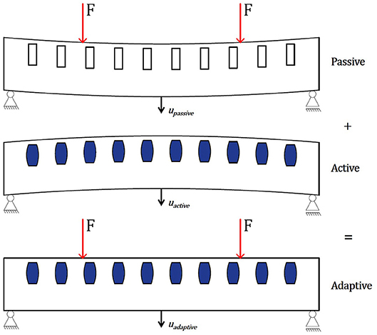
Figure 1. Concept of adaptive beams with integrated actuators. Passive state (Top); active state (Middle); and adaptive state (Bottom).
To prove this concept, an analytical approach is derived in section Analytical Approach, which is numerically and experimentally validated on a 1,200 × 200 × 100 [mm3] concrete beam in sections Numerical Simulation and Experimental Validation, using the finite-element method (FEM) and a universal testing machine (UTM), respectively.
Each actuator induces a pair of normal forces FA, i and a pair of bending moments MA,i. The actuation concept has no influence on the shear forces within the beam. The resulting force FA induced into the cross-section via an actuator is calculated from the hydraulic pressure pA and the available actuator cross-section AA (Janocha, 2004). Design measures are taken to ensure that the hydrostatic stress state from the applied hydraulic pressure in the actuators is largely restricted to one predetermined axis. Thus, a distinct orientation of the resulting force FA can be ensured, which lies strictly in the longitudinal axis of the beam. Since the actuator is located in the compression zone, the distance between the actuator center and the axis of gravity of the beam hA results in a moment MA (cf. Figure 2). For a single actuator i, the relationship can be written as:
A first approach to determine the necessary pressures pA is to use an equilibrium of moments. The moment generated by the actuators MA should be equal to the moment from external load Mq:
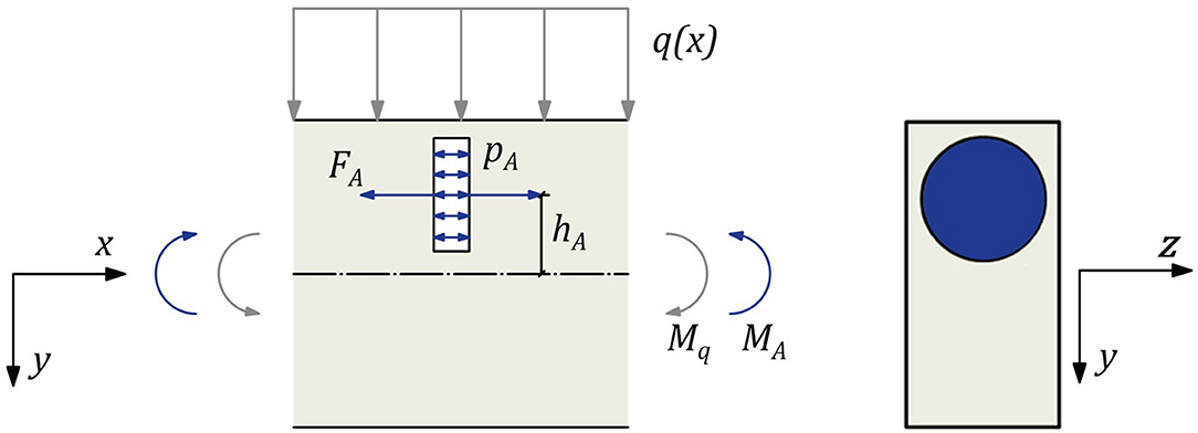
Figure 2. Detail of a beam with one actuator.
If the passive moment Mq increases, the induced active moment must be raised accordingly by the same amount but with opposite sign. Since the active bending moment of one actuator MA,i only acts locally, more than one or rather multiple actuators should be arranged along the entire longitudinal axis of the component. The theoretical bending moment diagram for a one-dimensional beam, using a simple strut and tie model, with 10 actuators is shown in Figure 3.
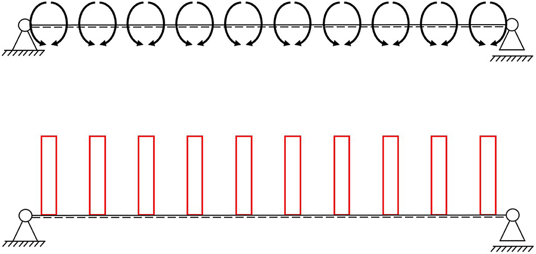
Figure 3. Single-span beam with 10 actuators with the same hydraulic pressure (Top) and the theoretical bending moment diagram (Bottom).
For the building industry in particular, a prediction of the occurring loads is very difficult, in many cases even impossible. Therefore, an adjustment of the individual active bending moments MA,i generated by the actuators is desirable. This could be done by changing the distance hA of the actuators to the neutral axis, by reducing the size of each actuator's area AA,i or by individually adjusting the pressure pA,i. Of those parameters, only the adjustment of the hydraulic pressure pA,i can be repeatedly varied. Thus, this concept will be pursued further. By adapting the pressure, the bending moment diagram from the actuators can be adapted to counteract the bending moment caused by the external load.
Figure 4 shows the bending moment diagram of a four-point bending test. In this example, some actuators should be pressurized differently. The internal hydraulic pressure should be the same for all actuators between the application position of the two point loads and lower for the actuators toward the support, generating an oppositely directed bending moment diagram (see Figure 5).
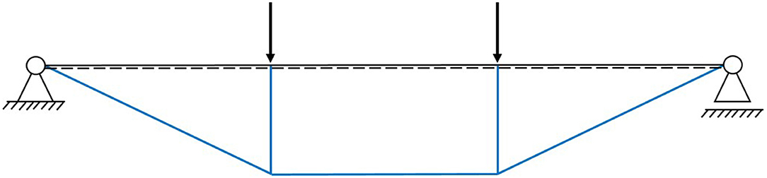
Figure 4. Single-span beam with two single loads and the corresponding bending moment diagram.
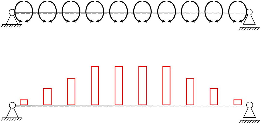
Figure 5. Induced moments by 10 actuators (Top) and the bending moment diagram as a reaction to two symmetrical loads (Bottom).
Further examples can be found in Kelleter et al. (2019).
This far, all shown examples (cf. section Theoretical Bending Moment Diagrams) are statically determined, which is often preferred to avoid restraint forces. The normal forces induced by the actuators are short-circuited locally, along each actuator, as the beam can expand or contract freely. This means that the areas between the actuators are theoretically stress free, while the areas around the actuators are not (see Figure 6).
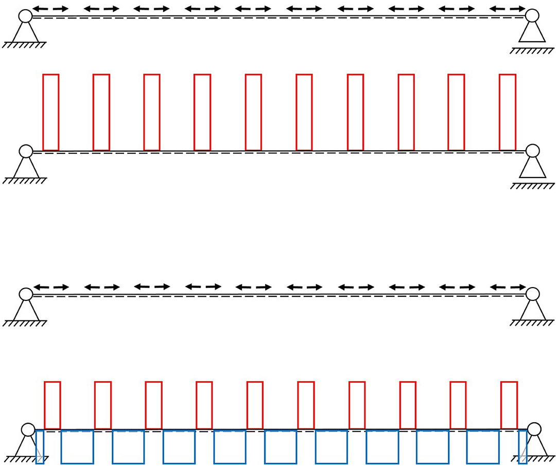
Figure 6. Normal force diagram of a statically determinate (Top) and statically indeterminate (Bottom) single-span beam.
If the beam elongation is constrained (statically indeterminate), not only the stress in the area of the actuators can be manipulated, but also the stresses between the actuators. More precisely, it is possible to compress the spaces between the actuators, due to an expansion of the latter (see Figure 6). Although constraints are usually avoided, for concrete beams with integrated actuators, this seems to lead to a distribution that consists of compression only.
The ratio of compressive forces in the beam in Figure 6, between the actuators (blue) and tensile forces (red) around the actuators, is dependent on the ratio of stiffness of those areas. In previous studies on adaptive truss structures, a distinction was made between parallel and serial actuation (Weidner et al., 2019). With the actuator being surrounded by concrete on all sides, the shown actuation concept can be considered parallel (cf. Figure 2). If the stiffness around the actuators is zero, this actuation concept would be closer to a serial actuation. This article on integrated actuators focuses on reducing deflection and the bending moment; therefore, the normal and shear forces are not discussed further. The parallel and serial actuation of truss structures is examined in more detail in Steffen et al. (2020).
The shown analytical approach is applied to the chosen adaptive beam (1,200 × 200 × 100 [mm3]), loaded in the four-point bending setup (cf. Figures 1, 4), with a distance between the supports of 1,000 mm (cf. section Experimental Validation), as a first simplified approach to determine the needed pressures. It is assumed that both point loads F are 4 kN, leading to a maximum bending moment Mq of 1.33 kNm.
From the resulting passive bending moment diagram, the needed pressures can be calculated by solving Equation (4) for the pressure.
All actuators are assumed to be thin cylindrical discs (cf. Section Experimental Validation), with a diameter of 80 mm, resulting in an area AA of 5026.5 mm2. Each actuator is positioned in the center of the upper half of the cross-section (cf. Figure 2), leading to an inner lever hA of 50 mm. The position was chosen so that the lever arm hA is maximized, while keeping the actuators evenly surrounded by concrete. Ten actuators are placed along the longitudinal axis of the beam with an interval of 100 mm, with the first actuator being placed at a distance of 50 mm from the first support. The equidistant arrangement was derived through FE analysis (cf. section Numerical Simulation). The calculated pressures are presented in Table 1 and further used for the numerical simulations in section Numerical Simulation.

Table 1. Calculated hydraulic pressure in each actuator.
The example from Section Analytical Approach is further validated through numerical simulations through FE analysis. The determined hydraulic pressures are adjusted if necessary. The beam has been modeled with the software ABAQUS and consists of solid elements C3D10 with an approximate element size of 2 mm (cf. Figure 7). The C3D10 element is a second-order tetrahedral element with 10 nodes and four integration points. A comparison between a model in which the actuators were fully modeled and a model in which the actuators were simplified as a cavity in the beam showed that this simplification does not affect solution accuracy significantly. Therefore, the actuators were idealized as a cavity with a surface pressure applied on the xy-plane, which is set to the pressure given in Table 1 (see Figure 7).
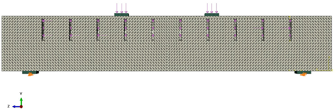
Figure 7. Finite-element method model with loads, boundary conditions, and 10 actuators. Concrete in gray and steel in green.
Since a linear elastic behavior is assumed (in the best-case scenario, the beam has no deflection at all), a linear elastic material is defined. A conventional concrete C35/45 is used, which is modeled with a modulus of elasticity of 34,000 N/mm2. The support flats and load introduction flats were also modeled in accordance with the experimental setup of Section Experimental Validation. These flats were made of steel with a modulus of elasticity of 210,000 N/mm2 and were meshed with eight node brick elements C3D8R.
The symmetry of the beam is used to save calculation time. Only half of the beam is created and provided with the necessary boundary conditions (displacement-x = rotation-y = rotation-z = 0) (see Figure 7). One support restricts vertical (displacement-y = 0) and horizontal (displacement-z = 0) movement, and the other one restricts vertical movement only. To allow for rotations of the supports, their translational boundary conditions are not applied over the entire surface of the support flat, but only along a line parallel to the x-axis (cf. Figure 7). Between the steel flats and the concrete beam, a frictionless surface-to-surface contact is defined to take the polytetrafluoroethylene layer into account, which will be placed between the steel flats and the cylinder segments in the experimental setup.
As explained in section Theoretical Normal Force Diagram, the forces induced by an actuator in the cross-section only act locally. Firstly, the stresses induced by each actuator decay or homogenize over the length of the beam, according to the principle of St. Venant (Mises, 1945). Secondly, the forces are short-circuited, since each actuator is surrounded by concrete (parallel actuation). Multiple actuators should be spaced depending on this effect. Thus, a separate FE analysis was done to estimate the distances between the actuators. A beam with only one actuator with a hydraulic pressure of 53 bar (cf. Table 1) and no external load is simulated (see Figure 8). The maximum stress in longitudinal direction from actuation results in the area next to the actuator (5.3 N/mm3). As the stress fields of two adjacent actuators overlap, the spacing of the actuators is chosen to be determined by the distance over which the maximum stress induced by one actuator reduces by at least 50%. In the given model, the maximum stress decreases from 5.3 N/mm2 to 2.66 N/mm2 over a distance of approximately 50 mm, resulting in a spacing of 100 mm for the actuators. This leads to 10 actuators for the given span of 1,000 mm. The quality of this estimation is evaluated through experimental investigations and modified if necessary.
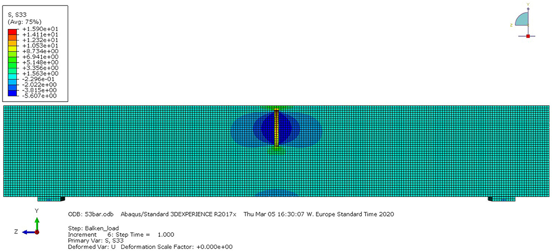
Figure 8. Beam with one actuator to calculate the distance between the actuators.
The simulations with 10 actuators show that the deflection resulting from two external point loads of 4 kN each and the dead load of the beam can be reduced from upassive = 0.00815 mm to uadaptive = 0.00285 mm (see Figure 9). In this simulation, all actuators have a hydraulic pressure of 53 bar, because in the tests, the pressure was not individually adjusted for each actuator (cf. section Experimental Validation).
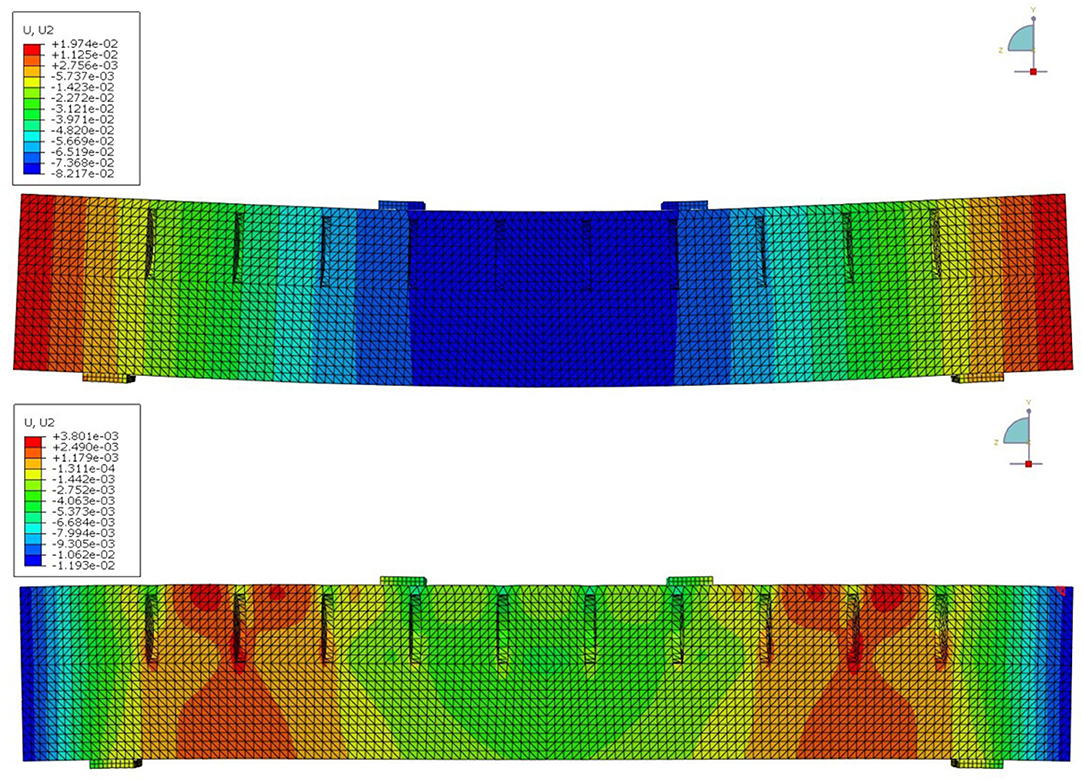
Figure 9. Vertical displacements of the adaptive beam under external load with 0 bar internal pressure (Top) and with 53 bar (Bottom), up-scaled by a factor of 200.
Results obtained from the FE analysis are experimentally validated in a four-point bending test series. The beam rests on two support plates, which, separated by an intermediate polytetrafluorethylene layer, rest on half cylinders. A UTM applies the external load via two steel plates and the deflection of the beam is measured at mid-span with two inductive displacement transducers. The experimental setup is visualized in Figure 10. The test is carried out by first letting the structure deform under the external load and then compensating the deflection by the hydraulic pressure in the actuators. This process takes place successively in order to observe the behavior of the beam in each state. For simplicity, in this series of test, the pressure is not varied for each actuator individually, as shown in section Analytical Approach. Instead, the same pressure is applied to each actuator at the same time.
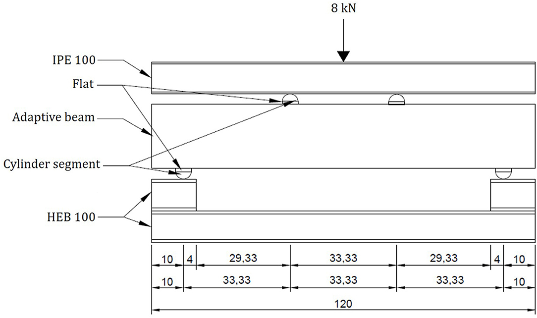
Figure 10. Experimental setup for the four-point bending tests. All measurements in centimeters.
The actuators were specifically developed for integration in concrete beams. As maintenance is not possible, no wear parts are used. Due to the minimal deformations of the concrete, the actuators also only have to generate minimal displacements. Thus, in order to completely eliminate the use of parts subjected to wearing, only the elastic deformations of the actuators are utilized. However, large forces must be generated to actuate the beam. Among the many actuator operating principles, hydraulic was chosen because it can generate the required forces and at the same time it can react quickly. In addition, hydraulic pressures can be transmitted directly to the concrete structure.
Each actuator consists of three layers, two external steel sheets with 1 mm wall thickness, and an internal core with 2 mm thickness, which stiffens the actuator in radial direction. Despite hydrostatic internal pressure, forces can be introduced exclusively in the axial direction of the beam, by positioning the actuators accordingly. The actuators are disc-shaped with a diameter of 80 mm (see Figure 11). The three layers are welded all around and connected to a supply line for the hydraulic oil with a diameter of 4 mm. A visual prototype, showing the section of a concrete beam, is depicted in Figure 12. Each actuator is connected to a hydraulic power unit via its supply line pipe (cf. Figure 11). The pressure in each actuator can be individually adjusted via solenoid valves and hydraulic pressure transmitter, which are both attached to the hydraulic power unit (for simplicity, in this test series, the pressure in the actuators is not adjusted individually). The control loop with all additional components is shown in Kelleter et al. (2019).
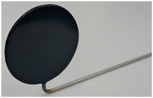
Figure 11. Actuator used in the experimental validation.
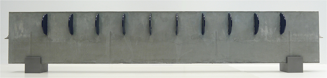
Figure 12. Prototype with only one half poured with concrete and 10 integrated actuators. Length = 1,200 mm.
Figure 13 shows the measurement results of a test with an actuated beam under four-point bending load.
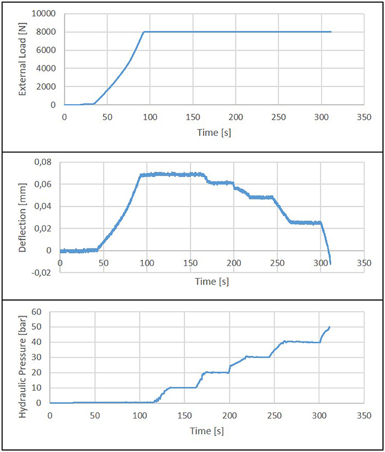
Figure 13. Results of a four-point-bending test: external load (Top), mid-span deflections of the beam (Mid), hydraulic pressure inside the integrated actuators (Bottom).
Initially, the beam is loaded with 8 kN. This load is kept constant under force control for the rest of the test duration. After reaching the maximum external force, the hydraulic pressure inside the integrated actuators is increased continuously in steps of 10 bar. As can be seen in the bottom diagram in Figure 13, the mid-span deflection is fully compensated at a pressure of approx. 47 bar. Increasing the pressure further, the beam can even be bent upwards (positive curvature).
At a pressure above 50 bar, the first cracks appear at the outer ends on the upper surface of the beam, i.e., in the normally compressed zone. This failure behavior coincides with the theory. Since there is less compressive stress due to the bending moment (above the supports, the bending moment is almost zero), the pressure of the actuators, which is not adapted to the moment characteristic, leads to failure in these areas. In the tested beams, there is no reinforcement in the upper part, which is compressed in the passive state and under tension when the beam has a negative vertical deflection, although in real beams, there is most likely reinforcement in the compression and tension zone as a secondary reinforcement.
The test results and the results of the FEM simulation are compared in Figure 14. In the unpressurized state, the simulated deflection is greater than the measured deflection. This is due to the fact that the actuators are not modeled (see section Numerical Simulation) and therefore the supporting effect of the actuator housing is not taken into account. Between 10 and 40 bar, there is good accordance between numerical and experimental results. The deviation at 50 bar is due to the ideal elastic material model on which the simulation is based. Due to the cracking of the concrete, when the beam is rising upwards, this model cannot accurately predict the response of the structure.
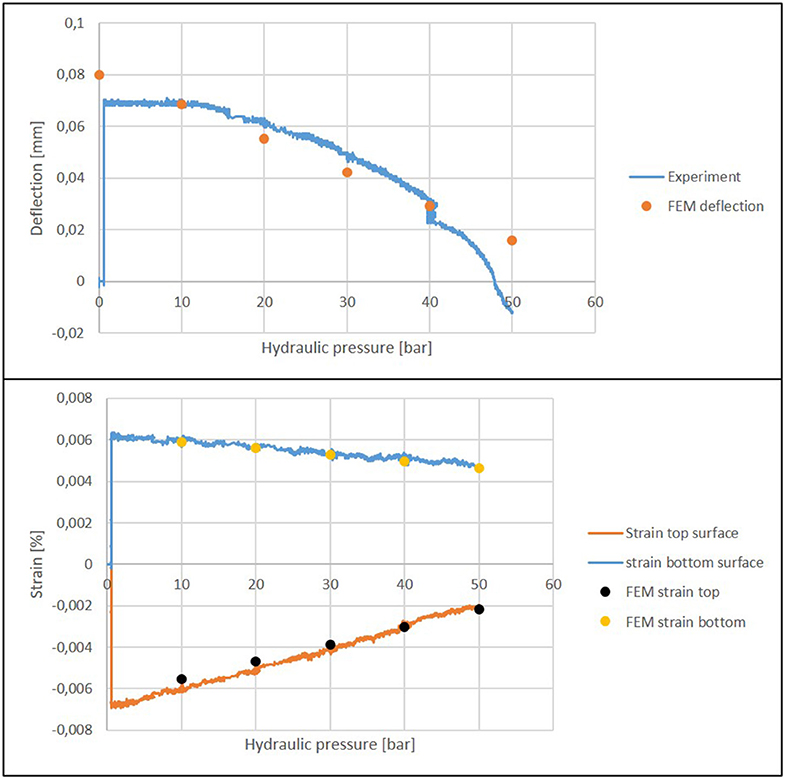
Figure 14. Compensation of the deflection (Top) and strains (Bottom) as a result of hydraulic pressure.
Another parameter used for validation are the strains. Two strain gauges are attached to the beam. One on the top surface and one on the bottom surface, both placed in mid-span. The calculated strains are very close to the measured strains, verifying the FEM model (see Figure 14). Both strain values are significantly reduced. The strain at the top side of the beam is reduced much more than the strain at the bottom side. This observation is in good accordance with theoretical predictions. This is because the actuators not only reduce the bending moment and therefore the deflection, but also induce a pair of normal forces (cf. section Numerical Simulation). At the top, where the actuator is closer to the surface, the effect of the elongation due to the pair of normal forces is higher than at the bottom (St. Venant principle).
In this paper, it was shown that the deflection of a concrete bending beam can be minimized by means of integrated fluidic actuators. Based on the presented example of a beam on a reduced scale, the concept was derived with analytical preliminary considerations and with FEM simulations. Simulation results were validated experimentally. There is good accordance between numerical and experimental results in the linear elastic range.
The entire compensation of the deflection of components subjected to bending allows a new way of dimensioning. The approach of integrating the actuators into the cross-section allows one to react, unlike many other adaptive structures, to a wide range of load cases in an optimal way. By transforming the stiffness problem of beams into a strength problem, this approach has a great mass and energy saving potential. How much material and energy are saved depends on the individual scenario (span, maximum load levels of external loads, probabilities of occurrence, etc.). In the example shown, however, the full compensation of deflection is highly promising.
The next step is to calculate the material savings that can be achieved through the shown concept. This is an iterative process, since a reduction of the cross-section means that the actuators must also be reduced in size. As a consequence, the resulting actuator force is lower for a given pressure. The proven concept in this paper is limited to static loads, but the developed actuators can also compensate for vibrations. The hydraulic power unit can increase the pressure almost in real time, since small changes in volume are sufficient.
The original contributions presented in the study are included in the article/supplementary material, further inquiries can be directed to the corresponding author/s.
WS initiated the research project. TB and CK did the experimental testing under the guidance of WS, HB, and LB. The analytical approach was developed by CK. The numerical studies were done under the guidance of WS by CK. The first draft was written by TB and CK. All authors actively revised, reviewed, and approved the final submission.
The work described in this paper was conducted in the framework of the Collaborative Research Center 1244 Adaptive Skins and Structures for the Built Environment of Tomorrow/project C02 Integrated fluid-actuators funded by the GermanResearch Foundation (DFG—Deutsche Forschungsgemeinschaft).
The authors declare that the research was conducted in the absence of any commercial or financial relationships that could be construed as a potential conflict of interest.
The authors are grateful for the generous financial support and wish to express their gratitude therefor.
Berger, T., Patrick, P., and Hans Georg, R. (2013). Einsparung von grauer energie bei hochhäusern. Beton Stahlbetonbau 108, 395–403. doi: 10.1002/best.201300019
Block, P., van Mele, T., Matthias, R., and Noelle, P. (2017). Beyond Bending: Reimagining Compression Shells: DETAIL Special. 1st Edn. Munich: Edition DETAIL.
DIN Deutsches Institut für Normung (2009). Eurocode 1: Einwirkungen Auf Tragwerke – Teil 1-3: Allgemeine Einwirkungen, Schneelasten; Deutsche Fassung (Berlin: Beuth Verlag GmbH).
Domke, H., Backe, W., Meyr, H., Hirsch, G., and Goffin, H. (1981). Aktive verformungskontrolle von bauwerken. Active deformation control of buildings. Bauingenieur 56, 405–412.
European Commission (2019). Taking Action on the Total Impact of the Construction Sector.” level(s). unpublished manuscript. Avaliable online at: https://ec.europa.eu/environment/eussd/pdf/LEVEL(S)%20CONFERENCE%20REPORT.pdf (accessed October 30, 2019).
Gross, D., Werner, H., Schröder, J., Wall, W. A., and Javier, B. (2018). Engineering Mechanics 2: Mechanics of Materials. 2nd Edn. Berlin, Heidelberg: Springer Berlin Heidelberg.
Kelleter, C., Timon, B., Hansgeorg, B., and Werner, S. (2018). “Actuation concepts for structural concrete elements under bending stress,” in Proceedings of the 6th. European Conference on Computational Mechanics (Solids, Structures and Coupled Problems) ECCM 6, edited by International Center for Numerical Methods in Engineering, eds. S.L. Huelva (Spain, Cornellà de Llobregat: Artes Gráficas Torres), 127–37.9, 08940. Available online at: http://www.eccm-ecfd2018.org/frontal/docs/Ebook-Glasgow-2018-ECCM-VI-ECFD-VII.pdf
Kelleter, C., Timon, B., Hansgeorg, B., and Werner, S. (2019). “Actuation of structural concrete elements under bending stress with integrated fluidic actuators,” in Advances in Engineering Materials, Structures and Systems: Innovations, Mechanics and Applications : Proceedings of the 7th International Conference on Structural Engineering, Mechanics, and Computation (SEMC) 2019, eds A. Zingoni (Boca Raton: CRC Press), 1005–1009.
Milliman, J., and Syvitski, J. P. M. (1992). Geomorphic/tectonic control of sediment discharge to the ocean: the importance of small mountainous rivers. J. Geol. 100, 525–44. doi: 10.1086/629606
Mises, R. V. (1945). On saint venant's principle. Bull. Amer. Math. Soc. 51, 555–563. doi: 10.1090/S0002-9904-1945-08394-3
Mitchel, J. C. (2008). The Concrete Conundrum. Chemistry World, 62–68. Avaliable online at: https://www.rsc.org/images/Construction_tcm18-11(4530).pdf (accessed August 27, 2019).
Neuhäuser, S. (2014). Untersuchungen zur homogenisierung von spannungsfeldern bei adaptiven schalentragwerken mittels auflagerverschiebung. (Ph.D. Dissertation). Institut für Leichtbau Entwerfen, Konstruieren, Universität Stuttgart.
Pacheco, P., André, A., Teresa, O., and Pedro, B. (2010). Automation robustness of scaffolding systems strengthened with organic prestressing. Automat. Construct. 19, 1–10. doi: 10.1016/j.autcon.2009.09.001
Schlegl, F., Honold, C., Leistner, S., Albercht, S., Roth, D., Hasse, W., et al. (2019). Integration of LCA in the planning phases of adaptive buildings. Sustainability 11:4299. doi: 10.3390/su11164299
Schnellenbach-Held, M., Daniel, S., Abdalla, F., and Oliver, K. (2014). Adaptive spannbetonstruktur mit lernfaehigem fuzzy-regelungssystem. Bauingenieur 89, 57–66.
Scrivener, K., Vanderley, J., and Ellis, G. (2016). Eco-efficient cements: potential economically viable solutions for a low-CO2 cement-based materials industry. Cement Concrete Res. 114, 2–26. doi: 10.1016/j.cemconres.2018.03.015
Senatore, G., Philippe, D., Pete, W., and Chris, W. (2018). Shape control and whole-life energy assessment of an ‘Infinitely Stiff' prototype adaptive structure. Smart Mater. Struct. 27:1. doi: 10.1088/1361-665X/aa8cb8
Senatore, G., Philippe, D., and Peter, W. (2019). Synthesis of minimum energy adaptive structures. Struct. Multidisc Optim. 60, 849–77. doi: 10.1007/s00158-019-02224-8
Setareh, M., and Darvas, R. (2016). Concrete Structures. 2nd Edn. (Switzerland: Springer). doi: 10.1007/978-3-319-24115-9
Sobek, W. (2016). Ultra-Lightweight construction. Int. J. Space Struct. 31, 74–80. doi: 10.1177/0266351116643246
Sobek, W., Stefan, N., Walter, H., Oliver, S., and Martin, W. (2013). “Ultralightweight structures.” in Proceedings of IASS Annual Symposia (Wrocław). 2013, 1–9.
Steffen, S., Stefanie, W., Lucio, B., and Werner, S. (2020). Using influence matrices as a design and analysis tool for adaptive truss and beam structures. Front. Built Environ. 6, 1–12. doi: 10.3389/fbuil.2020.00083
Teuffel, P. (2004). Entwerfen adaptiver strukturen: lastpfadmanagement zur optimierung tragender leichtbaustrukturen. (Ph.D. Dissertation). Institut für Leichtbau Entwerfen und Konstruieren, Universität Stuttgart.
United Nations Environment Programme. (2014). “Sand, Rarer Than One Thinks: UNEP Global Environmental Alert Service. Avaliable online at: http://hdl.handle.net/20.500.11822/(8665) (accessed March 2014).
Weidner, S., Simon, S., and Werner, S. (2019). The integration of adaptive elements into high-rise structures. Int. J. High Rise Buildings 8, 95–100. doi: 10.21022/IJHRB.2019.8.2.95
Weidner, S., Christian, K., Paula, S., Walter, H., Florian, G., Timon, B., et al. (2018). The implementation of adaptive elements into an experimental high-rise building. Steel Construct. 11, 109–17. doi: 10.1002/stco.201810019
Keywords: adaptivity, lightweight construction, beams, slabs, simulation
Citation: Kelleter C, Burghardt T, Binz H, Blandini L and Sobek W (2020) Adaptive Concrete Beams Equipped With Integrated Fluidic Actuators. Front. Built Environ. 6:91. doi: 10.3389/fbuil.2020.00091
Received: 07 April 2020; Accepted: 26 May 2020;
Published: 22 July 2020.
Edited by:
Gennaro Senatore, École Polytechnique Fédérale de Lausanne, SwitzerlandReviewed by:
Marios C. Phocas, University of Cyprus, CyprusCopyright © 2020 Kelleter, Burghardt, Binz, Blandini and Sobek. This is an open-access article distributed under the terms of the Creative Commons Attribution License (CC BY). The use, distribution or reproduction in other forums is permitted, provided the original author(s) and the copyright owner(s) are credited and that the original publication in this journal is cited, in accordance with accepted academic practice. No use, distribution or reproduction is permitted which does not comply with these terms.
*Correspondence: Christian Kelleter, Y2hyaXN0aWFuLmtlbGxldGVyQGlsZWsudW5pLXN0dXR0Z2FydC5kZQ==
Disclaimer: All claims expressed in this article are solely those of the authors and do not necessarily represent those of their affiliated organizations, or those of the publisher, the editors and the reviewers. Any product that may be evaluated in this article or claim that may be made by its manufacturer is not guaranteed or endorsed by the publisher.
Research integrity at Frontiers
Learn more about the work of our research integrity team to safeguard the quality of each article we publish.