 Iolanda Nuzzo
 Francesca Ciliento
 Nicola Caterino
94% of researchers rate our articles as excellent or good
Learn more about the work of our research integrity team to safeguard the quality of each article we publish.
Find out more
ORIGINAL RESEARCH article
Front. Built Environ., 21 February 2020
Sec. Earthquake Engineering
Volume 6 - 2020 | https://doi.org/10.3389/fbuil.2020.00013
This article is part of the Research TopicRecent Advances and Applications of Seismic Isolation and Energy Dissipation DevicesView all 19 articles
This paper describes a comprehensive computer-aided seismic design approach for both new and existing frame structures equipped with hysteretic dampers. Despite continuous advancements in the state of the art demonstrating the effectiveness of these devices in mitigating seismic hazard, non-linearities involved in the problem and the articulated nature of most of the available design procedures often make them quite difficult to be implemented for real complex structures. To promote widespread use of hysteretic dampers, we present a thorough design approach that includes the application of a specific displacement-based design procedure by means of a computer-aided support tool developed in a Visual Basic environment and named DIBRAST. The software is realized to drive the designer through the dissipative system’s design. Required iterations are automated, thus significantly reducing the processing time. As its final output, it delivers the mechanical properties of the damping braces in order to meet a specific performance objective. In order to further support practitioners in the geometrical characterization of actual design dampers, authors developed an additional Visual Basic tool—the Shear Link Non-Linear Model—that is able to provide yielding force and elastic stiffness of a specific type of hysteretic device according to its geometry and material. In addition, geometric details of each device can be preliminary determined by means of newly proposed design charts, presented herein, that allow us to take into account the buckling issue too. Both developed tools are freely available online. A case study is provided to demonstrate the effectiveness of the proposed design approach and tools.
In recent years, the earthquake engineering research community has made a huge effort to develop structural vibration control systems for seismic hazard mitigation of new or existing structures. Nowadays, base isolation systems and energy dissipation devices represent a well-known solution to reduce the response of structures subjected to dynamic loads. Their proper functioning, within the family of passive control systems, does not require an external power supply or control algorithm, which is different to active or semi-active devices.
In this paper, the main focus is on metallic hysteretic dampers whose role, when embedded within the superstructure, is to absorb a portion of the seismic input energy through a mechanism involving the plastic deformation of their constitutive material. In this way, the inelastic demand on the principal framing system is reduced along with its damage, which is meant to be concentrated in the dampers. The idea of installing metallic dampers for seismic structural control was at first introduced by Kelly et al. (1972). Over the years, many authors have proposed various devices that have differing in shape and dissipative mechanisms (Javanmardi et al., 2019). Among them, Bergman and Goel (1987) and Whittaker et al. (1991) developed the Added Damping and Stiffness (ADAS) system; its dissipation capacity is based upon flexural deformation of X-shaped metallic plates connected at the top and bottom end to a rigid element, which thus does not allow for rotation. Based on the same functioning principle of ADAS, Tsai et al. (1993) proposed the Triangular-plate Added Damping and Stiffness (TADAS). Subjected to a lateral perpendicular force, triangular parallel metallic plates undergo uniform yielding along their height. Both ADAS and TADAS are commonly installed throughout moment-resisting frames on chevron brace supports. A rhombic ADAS damper was developed by Shin and Sung (2005) using low-yield strength steel with hinge supports at both ends. Kobori et al. (1992) introduced a honeycomb steel damper (or “panel system”) to increase energy absorption in high-rise buildings. It consists of a steel plate characterized by a honeycomb-shaped opening in the central part subjected to loads acting in its own plane. The buckling-restrained brace (BRB) is composed of an unbounded thin steel core encased in a concrete-filled steel tube (Watanabe et al., 1988; Clark et al., 1999). Energy dissipation is provided by axial deformation of the internal steel core while buckling is avoided by the external casing. BRBs exhibit their dissipation capacity even for a low displacement demand since they are able to yield for displacements of a few millimeters. The result is thus that they are suitable even for seismic retrofitting of stiff structures (De Domenico et al., 2019). Di Cesare et al. (2014) proposed the Hysteretic Damper (HD), whose dissipation capacity is based upon flexural deformation of low-carbon steel plates of a particular shape. Generally installed on chevron braces supports, the HD provides additional lateral strength and stiffness, thus contributing to limiting interstory drifts. A wide range of mechanical properties can be obtained by simply varying the dimensions of the thin steel plates. At first investigated at the University of Girona, Spain, by Cahís et al. (1997), Bozzo et al. (1998), Bozzo and Barbat (1999), Cahís (2000) the Shear Link (SL) consists of a steel panel with variable thickness along its height, and it can undergo significant inelastic shear deformations.
Despite the advancements in the state of the art, the use of hysteretic dampers as a seismic control system is not yet widely spread due to the lack of proper guidelines providing support for the design of structures equipped with hysteretic dampers. The European Standard for Anti-Seismic Devices (EN 15129, 2009) has established that the type of analysis, response spectrum, or time-history analysis, should be chosen according to the type of device. Despite this, no indications are provided for the definition of an appropriate response factor. At the same time, it strongly recommends performing a dynamic non-linear analysis when the equivalent damping ratio is higher than 15%. This threshold can actually be easily overcome in the case of hysteretic dampers due to their significant non-linear behavior. Certainly, a non-linear analysis can better predict the structural inelastic performances, particularly when performed by adopting sophisticated hysteresis models (Vaiana et al., 2018, 2019a; Mazza, 2019a) and numerical methods (Greco et al., 2018; Vaiana et al., 2019b). Nevertheless, it cannot be considered a practical tool for preliminary sizing of the dissipative system. To this aim, various authors have proposed many design procedures, often consisting of performance-based approaches. Special effort was also devoted to including the influence of the finite stiffness of the supporting braces on the overall response of both viscous and hysteretic dampers (Losanno et al., 2015, 2018, 2019). Kim and Choi (2004) proposed a methodology providing the required effective damping of BRBs at the target displacement. Bergami and Nuti (2013) developed an iterative procedure where a target damping ratio was defined according to a fixed displacement demand. Mazza and Vulcano (2015) proposed a framework to design the dissipative system according to a target deformation. Based on non-linear static analysis, Di Cesare and Ponzo (2017) introduced a design approach for the evaluation of the mechanical properties of dissipative systems that are given a target top displacement and are able to regularize strength and stiffness distributions along the height of the braced structure when necessary. In addition, the authors proposed an analytical formulation of the behavior factor of braced structures as a result of a wide parametric analysis. Ponzo et al. (2019) proposed a design approach for low-damage braced post-tensioned timber frames providing the mechanical properties of both post-tensioned and the hysteretic dissipative brace systems at the target displacement to achieve a reference level of seismic intensity. Mazza (2019b) developed a displacement-based design procedure to size hysteretic damped braces according to a target performance level, accounting for the degrading cyclic response of r.c. frame members by means of a combined plastic-damage hysteretic model (Mazza, 2019a). Nuzzo et al. (2019) introduced a comprehensive displacement-based design approach with a direct reference to effective parameters of the damping braces in a way that is suitable for professional applications. However, non-linearity involved in the problem and the iterative nature of most of the mentioned procedures often make them articulated and lacking in promptness, and it is thus of little attraction for practitioners. In order to promote the diffusion of hysteretic dampers as seismic control strategy for both new and existing structures, the authors believe that the development of a free online design tool, supplied with a user manual, may be decisive. It should be easily applicable, driving practitioners toward the implementation of a design procedure suitable for real applications. In particular, required input data should be clearly defined, while design output should allow for the effective size of the dissipative braces. In this perspective, the displacement-based design method proposed by Nuzzo et al. (2019) is believed to be suitable to this aim. Indeed, though it is still an iterative procedure, the authors demonstrated that the steps and iterations require only analytical computations and do not involve any iterative numerical structural analysis. This makes the procedure implementable within a computer-aided tool, thus supporting designers in the fulfillment of the several phases of the procedure. In the present study, a significant effort was undertaken by the authors in order to develop DIBRAST—DIssipative BRAced STructures—a tool in the Visual Basic environment. Its structure, described in this paper, directly revokes the steps of the design procedure previously proposed by the same authors (Nuzzo et al., 2019). The software automates the required iterations, finally providing the dissipative system’s mechanical properties needed in order to achieve the desired structural performance. Input parameters and the output of the software are outlined in next sections. Namely, a modal analysis and a pushover curve of the bare frame are required at the beginning in order to determine the equivalent capacity curve. After providing input seismic hazard parameters at the site of interest, the tool is able to build the design response spectrum with consideration for the equivalent damping ratio provided by the added hysteretic dissipation system at target displacement. During the application, some assumptions concerning the dissipative system’s ductility capacity and post-yielding-to-elastic stiffness ratio have to be made. Thereafter, the equivalent damped brace capacity curve is determined as the difference between the dissipative system and bare frame ones. The final output of the software consists of the dissipative system mechanical properties along each damped bay and story. Successively, the effective design dampers and braces can be easily tuned introducing mechanical properties of commercial devices, which are commonly available on the market.
A similar contribution was provided by DISIPA-SLB (Bozzo et al., 2019), a plugin for CSI and ETABS (2016) structural analysis software, implementing two iterative design procedures based on simplified linear analysis. This tool, despite being able to iterate autonomously the design procedure, gives the user little control over the target interstory drift, which has to be checked from the analysis at each iteration. Moreover, it was demonstrated that linear analysis overestimates shear forces in the dampers and, consequently, leads to the excessive oversizing of their supporting element (Ciliento, 2019).
Once the mechanical design properties of the added hysteretic damping system are defined, a practical design approach should also allow for the definition of the corresponding device’s geometry. This makes the procedure effective, complete, and, therefore, of interest to practitioners. At a preliminary design stage, the use of an analytical approach is preferable since it is suitable for the prompt association of a specific geometry to defined mechanical properties. It strongly depends on the typology of the adopted control device and needs to be defined as a function of it. As an additional achievement of this work, authors proposed a design approach to properly associate the mechanical properties of a specific type of damper, in particular the SL device previously introduced, to its geometry. Therefore, a further Visual Basic tool has been developed with the aim of determining SL elastic stiffness and yielding force as a function of its material and geometrical properties as well as boundary conditions. The analytical model besides the proposed tool has been developed in a previous work by the same authors (Nuzzo et al., 2019). Moreover, in order to further support the designer in the selection of the damper’s geometry, new design charts are proposed herein. Their description and mode of use are described.
To promote the adoption of metallic dampers as a seismic protection system, Nuzzo et al. (2019), proposed a comprehensive displacement-based design procedure that is suitable for both new and existing structures. The method is based on a closed-form analytical procedure and allows us to obtain a preliminary sizing of the dissipative system in few iterations. Besides modal and pushover analysis of the bare frame (F system) required at the beginning, further structural analyses are not necessary to achieve the final result. Its main objective is to provide the desired force–displacement capacity curve of the equivalent braced frame (BF system) given in Figure 1, i.e., the frame equipped with the damped brace system (DB system), according to a fixed performance point. The latter is evaluated starting from the target displacement of the bare frame, chosen according to the type of building (new or existing one) and its class of importance (ordinary or mission critical structure), and defining the corresponding level of force, taking into account the equivalent damping ratio provided by the hysteretic behavior of the dampers. All steps of the procedure are thoroughly described in Nuzzo et al. (2019). In this paper, authors propose DIBRAST, a practical tool developed in Visual Basic environment, given as a support in the application of the displacement-based design framework. The software is freely available online1, and it is accompanied by a related user manual. It implements all steps of the procedure, finally providing the desired mechanical properties of the dissipative braces in order to meet the performance objective. The user is guided on data to be input at each step in the only editable cells through pop-up notes, moving the cursor in correspondence with the input columns.
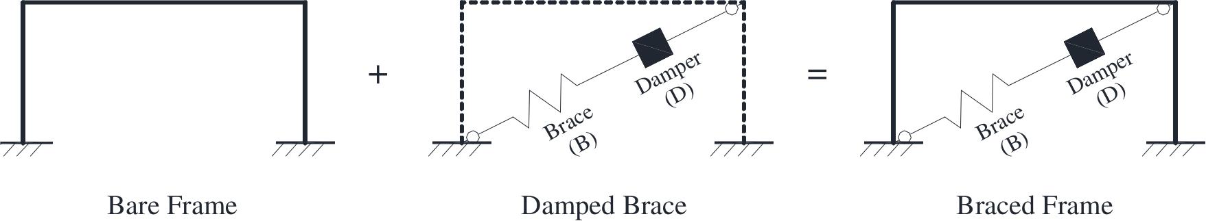
Figure 1. Schematization of the bare frame, damped brace, and braced frame systems.
In order to implement the design framework with the support of DIBRAST, there are several piece of information the user should input:
• Target displacement;
• F system capacity curve;
• Seismic hazard parameters;
• Number of bays to brace with dissipative systems at each story.
The tool will provide valuable information as its output:
• Identification of the Performance Point (PP);
• Capacity curves of BF and DB systems, plotted in the ADRS space together with those from the F system;
• Mechanical properties of each dissipative system in terms of yielding force and elastic stiffness;
• Ductility check of the j-th damper at i-th story.
The design procedure requires two different types of iteration to be implemented. The first is needed in order to determine PP: it is automatically and autonomously solved by DIBRAST and does not require any particular action from the user. The second type of iteration must be performed at the end of the procedure in order to verify initial assumptions relative to DB system mechanical properties, as this will be clarified in the following sections. In this case, DIBRAST checks if the iteration is needed and, if this is the case, suggests the new values to be implemented by the user through a warning box until convergence is achieved. Although it involves the user, also this type of iteration is significantly simplified and reduces processing time.
DIBRAST software is divided into four sections, given that steps 2–3 and steps 5–6 of the design procedure are processed together, as shown in Figure 2 and as described in the following sections.
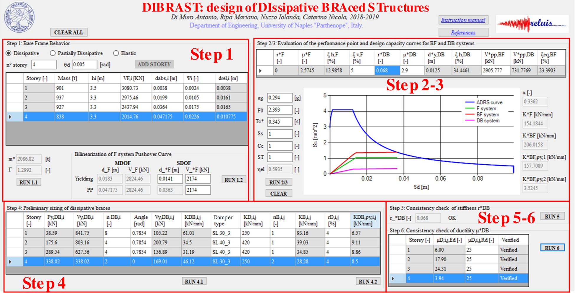
Figure 2. Screenshot of DIBRAST: a tool for preliminary sizing of dissipative systems.
In section 1 of the software, a linear or non-linear configuration for the bare frame (F system) has to be chosen, and the target displacement will be set accordingly. Namely, F could be dissipative, partially dissipative, or elastic. In case of dissipative or partially dissipative behavior, a target interstory drift (θd) can be set considering the maximum allowable plastic hinge rotation according to code provisions or reparability issues, respectively. Alternatively, for elastic behavior, θd can be defined in order to limit damage to non-structural elements. Once the pushover curve of the F system is known, the shear force distribution along the height (VF,i) and the absolute story displacements (dabs,i) in correspondence of the target displacement have to be defined in the editable cells along with the first modal shape (Ψi). Also, seismic masses are input by arranging permanent and live loads in a seismic combination. Modal participation factor (Γ) and equivalent mass (m∗) are given automatically as an output, allowing to determine the F single-degree-of-freedom (SDOF) system capacity curve. A further action is required by the user in order to determine the F system bilinear capacity curve.
Section 2–3 of the tool implements the analytical procedure for the evaluation of the performance point described by the following equations (Mazza and Vulcano, 2015; Nuzzo et al., 2019):
In the above equations, the bare frame parameters, namely ductility demand μ, post-to-pre yielding stiffnesses ratio r, needed to get the hysteretic damping ratio ξh,F (Eq. 2, Dwairi et al., 2007), and the base shear at PP () are known from step 1. The F system viscous damping ratio ξv,F shall be supposed according to the structural typology. Differently, in order to evaluate the DB hysteretic damping ratio ξh,DB (Eq. 3), ductility and post-to-pre yielding stiffnesses ratio, μ and r, initially unknown, have to be supposed at this point and will be checked by the end of the procedure. Moreover, k is a reduction factor that accounts for cyclic degradation (ATC, 1996).
The solutions of Eqs (1) and (4), concerning the equivalent BF damping ratio (ξeq,BF) and the equivalent DB base shear at PP (), respectively, depend on each other. Consequently, in order to apply Eq. (4), the user must give a first trial value of the equivalent base shear of the braced frame system () that is greater than . Hence, the software automatically implements some iterations until convergence is reached, giving, as a result, and ξeq,BF. Once the performance point is determined, the desired capacity curve of the global equivalent structure (BF system) is evaluated by solving Eqs (5–7), the latter only in the case of non-linear F systems:
where , and are the equivalent BF elastic and post-yielding stiffnesses, is the F system elastic stiffness, and α is the DB-to-F elastic stiffnesses ratio, which can be analytically determined (Nuzzo et al., 2019).
Then, the equivalent damped brace capacity curve is obtained as a difference between BF and F. Thereby, by the end of steps 2–3, capacity curves of F, DB, and BF systems are known and plotted together with the design Acceleration Displacement Response Spectrum (ADRS), i.e., they reduced by the equivalent damping ratio (Figure 3). In this section, the ADRS curve is defined with reference to the Italian design NTC code (Ministry of Infrastructures, 2018). However, any response spectrum according to international codes can be uploaded by defining equivalent parameters.
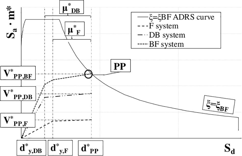
Figure 3. F, DB, and BF capacity curves vs. demand spectrum.
At step 4, the software delivers the required dissipative braces yielding force and elastic stiffness (Vy,DB,i and KDB,i) for each i-th story, assuming a proportionality criterion with respect to the modal behavior. Consequently, by only setting the number of braces at each level, the tool distributes the corresponding mechanical properties, finally providing a design-yielding force and elastic stiffness for each j-th dissipative brace at each story, Vy,DB,i,j and KDB,i,j. At this point, effective properties of dampers have to be specified by the user. To this aim, hysteretic devices can be designed according to a force criterion: known Vy,DB,i,j is the demanding shear force in each j-th dissipative system at i-th story, and the damper is chosen so that its yielding force matches the design force. Finally, once the elastic stiffness of the j-th damper at i-th story is known and input in DIBRAST (KD,i,j), the software provides the required elastic stiffness of the supporting element by solving the following equation:
Consequently, it is possible to size the support element, that may be given by steel elements, such as diagonal or chevron braces (Figure 4). This makes the procedure of significant impact for professional applications since it is characterized by high practicality.
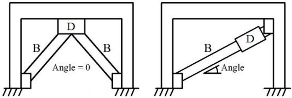
Figure 4. Supporting brace configuration (B = brace; D = damper).
As an additional feature, DIBRAST provides the post-yielding stiffness of the dissipative brace (KDB,py,i,j), once the damper’s post-yielding-to-elastic stiffness ratio is defined (rD,i,j). The latter parameter should be known for a specific hysteretic device from its experimental characterization. The provision of KDB,py,i,j can be helpful when performing non-linear time-history simulations.
Consistency check of DB post-to-pre yielding stiffness r takes place at step 5. DIBRAST analytically determines r value for the defined dissipative braces, and successively compares it to the initial assumption at step 2. If the results are not verified, a warning message box suggests the new value to be used to implement again the procedure from step 2. Each new iteration can be performed by simply running the successive steps of the tool. Finally, at step 6, the ductility demand μ for each dissipative brace is checked for compatibility with its capacity, and the latter is user defined.
The definition of dampers geometry according to design mechanical properties may often result in a demanding procedure, requiring time-consuming blind numerical simulations. Differently, an analytical approach is suitable for a prompt, preliminary sizing, driving the designer toward the correct order of magnitude of the required damper’s dimensions. In the state of the art, several typologies of hysteretic devices exist, and each is characterized by a different geometry and a specific working rule. Consequently, it is not possible to determine a design procedure available for a generic hysteretic damper, since a specific analytical model is needed for each of them. In the present work, authors developed a design tool with reference to the SL device. It consists of a metallic hysteretic damper realized from a hot laminated steel plate modeled as to obtain an I-shape (Nuzzo et al., 2015, 2018), shown in Figure 5. Top and bottom flanges represent the stiffer parts and are employed to realize the connection to other structural elements, while energy dissipation is concentrated in the web, corresponding with so-called dissipative windows. The latter are manufactured with a reduced thickness through a milling process, thus avoiding welding procedure. On the top part, the damper is provided of slotted holes to avoid axial forces from the upper beam due to gravitational loads.
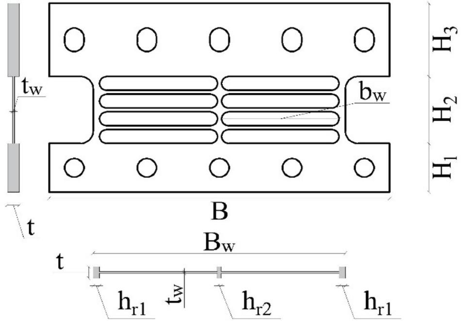
Figure 5. Shear Link damper.
Several generations of SL dampers have been developed in an attempt to enhance their dissipative performances assessed through several experimental campaigns. Investigations were first carried out at ISMES S.p.A in Bergamo (Italy) (Franchioni et al., 2001) and later on at the University of Girona (Hurtado and Bozzo, 2005; Hurtado, 2006; Hurtado and Bozzo, 2008). More recently, further tests were performed at the University of Naples (Nuzzo et al., 2018), showing quite stable hysteretic behavior of the damper under cyclic loading. Successively, Nuzzo et al. (2019) developed an analytical model to determine SL yielding force and elastic stiffness given its geometry, boundary conditions, and material. In particular, the yielding force is determined considering a pure shear behavior, knowing the material yielding shear stress and the web’s transversal area. On the other hand, the elastic stiffness has been evaluated through the principal of virtual works and accounting for both the shear and flexural behavior of the damper. In particular, the SL is modeled as a frame element characterized by different sections along its height. Two configurations have been considered, namely Fixed-Fixed (FF) and Fixed-Not Fixed (FNF) depending on whether upper bolts are fully tightened or not, thus accounting for the role of boundary conditions in the mechanical response of the device. The resulting analytical expressions characterizing the SL elastic stiffness can be find in Nuzzo et al. (2019), where the model’s accuracy was demonstrated through experimental comparison. In order to provide further support to the designer who wants to properly characterize a SL damper, the above analytical models, which result in long and unfriendly expressions, have been implemented in a Visual Basic environment, thus developing a Shear Link Non-Linear Model tool, given in Figure 6. The software is freely available online2, and this is accompanied by a relevant user manual. The required input parameters concern different areas:
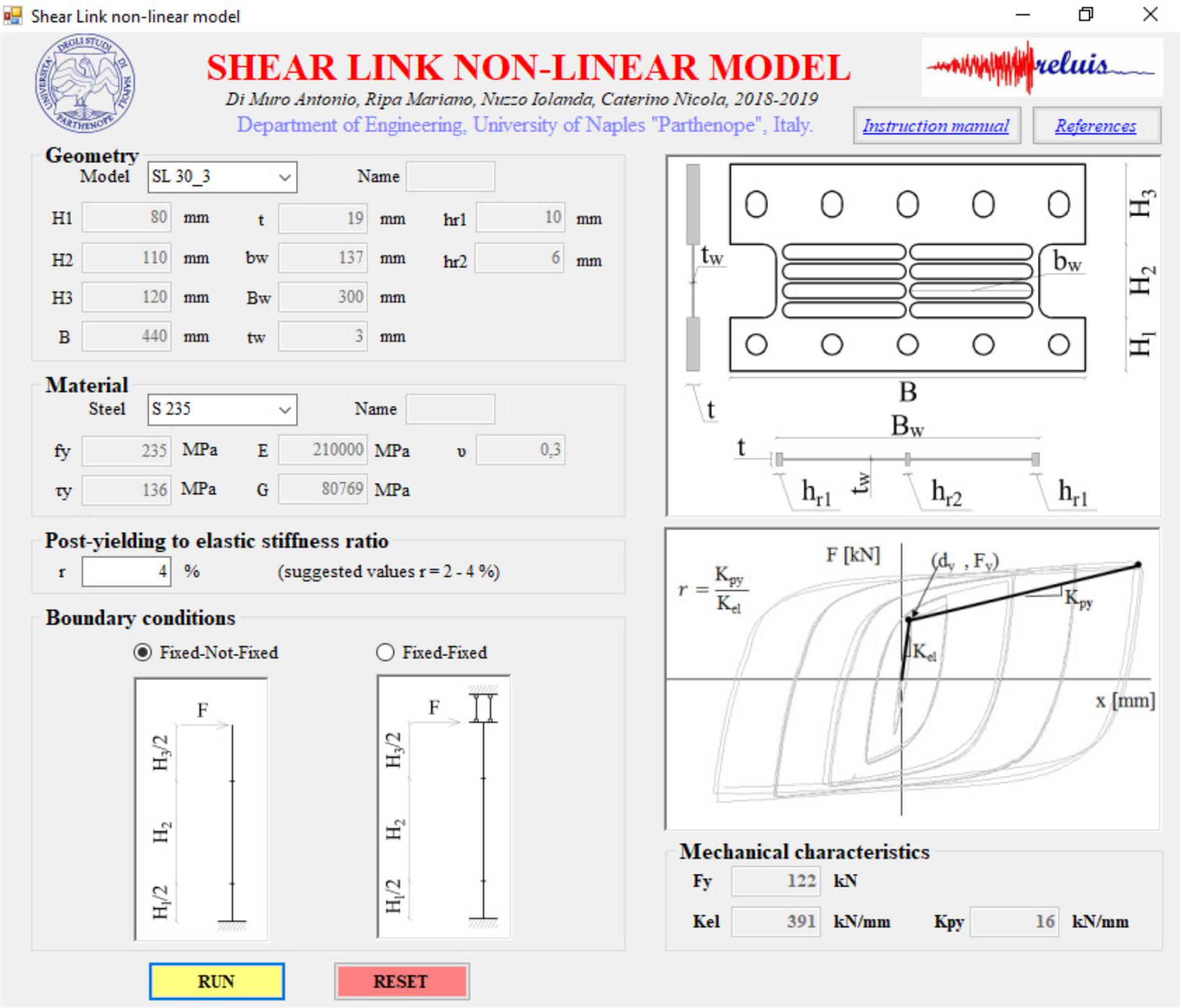
Figure 6. Screenshot of the Visual Basic tool to calibrate SL mechanical properties.
• essential geometric dimensions, described in the representation of the device within the tool, which can be selected from a dropdown list or are user defined;
• the type of material that can be selected among European commercial ones with precompiled mechanical properties or can be user defined;
• boundary conditions, which are directly represented in the tool.
The software implements the analytical model specifically developed for the SL damper, providing output in the form of estimated yielding force and elastic stiffness.
The use of the tool can be very handy for SL sizing, but it would still require a blind—though fast—design through iterative assessments. For this reason, the authors investigated the influence of SL geometry on the mechanical characteristics of interest, i.e., yielding force and elastic stiffness. In particular, a parametric study was developed varying the dissipative web’s thickness (tw), width (Bw), and height (H2). The results of this investigation have been arranged in new design charts, presented from Figure 7 to Figure 9, where the SL yielding force and elastic stiffness nomenclature are condensed as Fy and Kel.
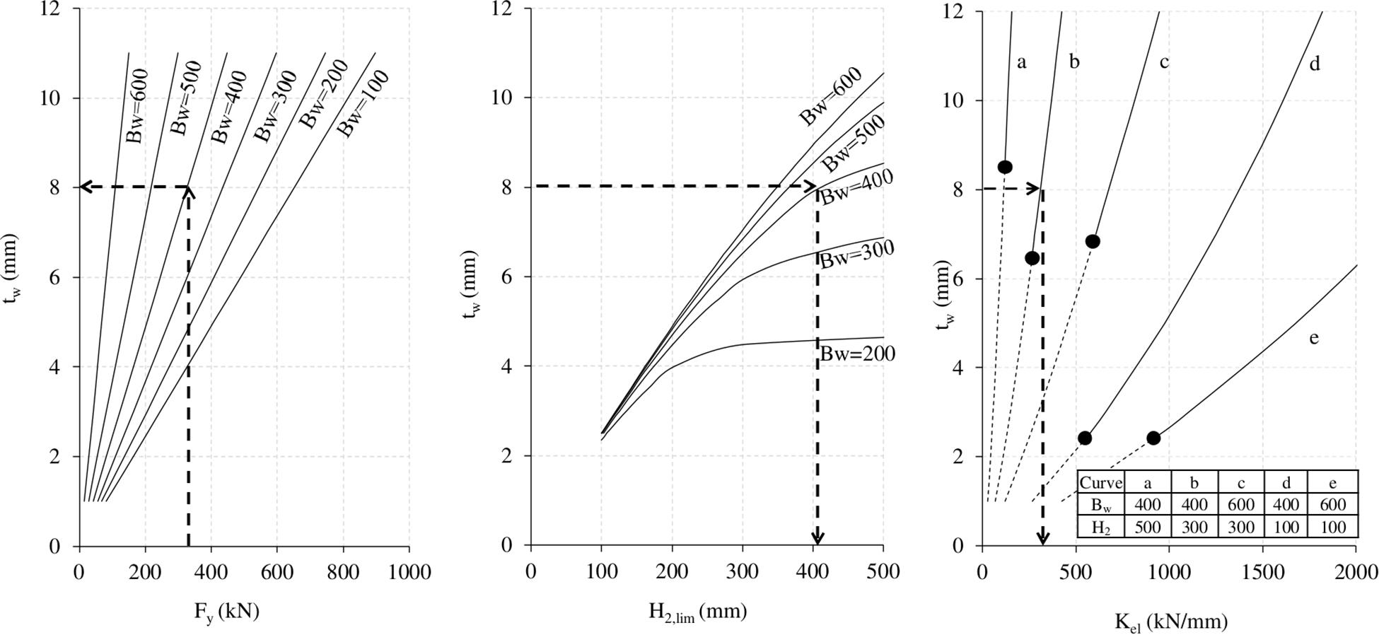
Figure 7. Preliminary design chart of SL devices (S235 steel grade; Bw and H2 expressed in mm).
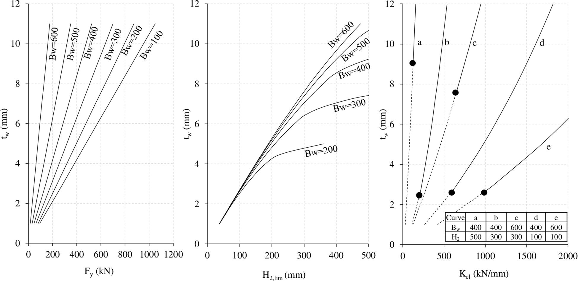
Figure 8. Preliminary design chart of SL devices (S275 steel grade; Bw and H2 expressed in mm).
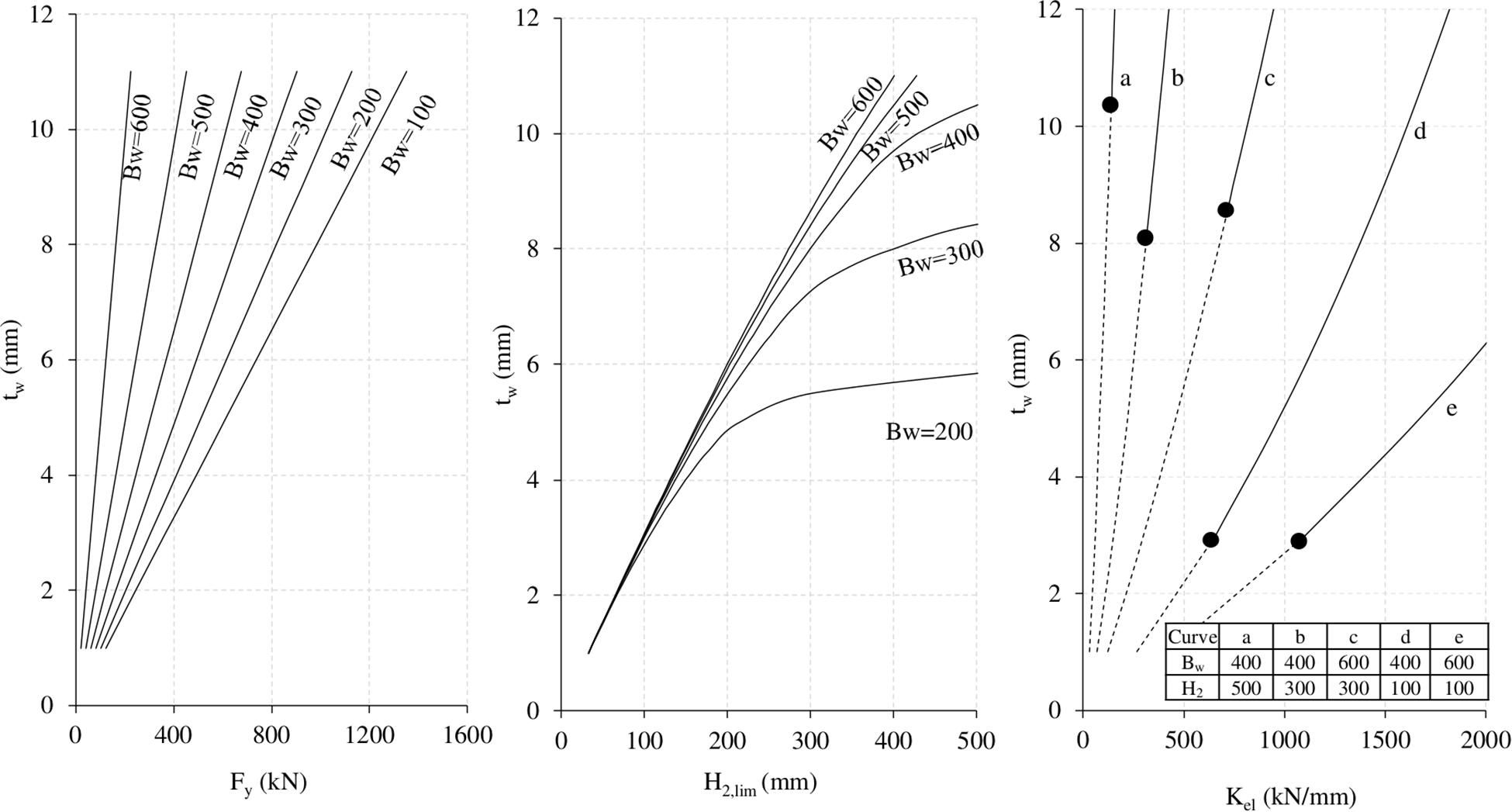
Figure 9. Preliminary design chart of SL devices (S355 steel grade; Bw and H2 expressed in mm).
The following charts have been developed considering the FNF configuration and given that, from authors experience, it represents the most commonly adopted solution. European S235, S275, and S355 standard steel grades have been considered.
The design chart is comprehensive of three different parts:
• in the left part, the yielding force is given as a function of tw, fixing Bw in different curves;
• the central plot describes the relation between the three investigated geometric dimensions, namely tw, Bw, and H2, providing the maximum limit of the web’s height avoiding buckling mechanism (Nuzzo et al., 2019);
• on the right side, the elastic stiffness is associated to tw, Bw, and H2. In addition, for different combinations of Bw and H2 parameters, corresponding to several curves (from a to e), the upper bound values of tw generating buckling (black dots in the right-side charts of Figures 7–9) have been determined. Thus, the dashed lines correspond to geometrical combinations which generate buckling, whereas the continuous lines represent suitable geometries.
An applicative example of the use of the proposed design charts is provided in Figure 7. It starts from the assumption that the SL yielding force is known. It can be assumed as the demanding yielding shear force (Vy,DB,i,j) of the j-th dissipative system at i-th story output of step 4 from the DIBRAST tool. Therefore, it is possible to enter in the left part of the design chart with the required Fy level and read the corresponding SL optimal tw after selecting Bw. The minimum possible value of the web’s width, compatible with the choice of a limited dimension of the web’s thickness, should be selected. In this way it is possible to optimize the device’s weight and cost, also simplifying the assembly procedure. Moreover, further issues that may influence the correct choice of Bw are the connection system and specific architectural requirements. Furthermore, in order to avoid buckling mechanism, a maximum Bw value of 600 mm is suggested, together with a minimum tw value of 3 mm (Nuzzo et al., 2019). At this point, entering in the central design chart in correspondence of selected tw and Bw values, the H2 upper limit preventing buckling mechanism can be read. Authors suggest considering a lower bound for H2 equal to 100 mm, in order to allow for the proper placement of the dissipative windows within the web. Finally, once H2 has been selected within the above range, entering the right side plot the designer can easily detect damper’s Kel. In addition, this chart allows to further check SL geometry with regards to buckling phenomenon, verifying it to be outside of the gray area.
The design framework proposed herein has been applied to the case study of an existing RC frame structure (Figure 10) situated in Norcia (central Italy). This structure was already assumed as a case study by the Italian Laboratories University Network of seismic engineering (ReLUIS) within a research project (2017–2018) investigating the application of different seismic control strategies. The building, designed and built in the early 1960s, hosts a public school and consists of three floors and a semi-underground level. The dimensions in the plan are 12.8 m × 58.9 m, while the interstory height is 3.5 m at the lowest floor and 3.3 m for the other levels for a maximum height of 16 m considering the sloping roof. Arranging permanent and live loads in seismic combination, seismic masses of 907 tons, 937 tons, and 838 tons have been defined for levels 1, levels 2–3, and for the top level, respectively.
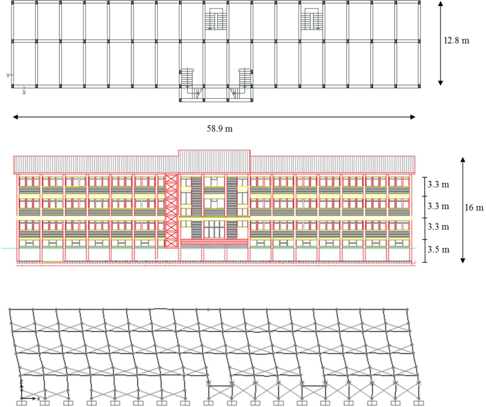
Figure 10. Plan and elevation views of the case study and first modal shape in x–z plane.
The seismic behavior of the as-built existing structure (F system) has been assessed in X direction through pushover analysis (CSI and SAP2000, 2019) according to NTC2018 (Ministry of Infrastructures, 2018), resulting in a satisfactory Life Safety (LS) limit state. The numerical 3D FEM model of the structure included clay-bricks infill walls modeled in compression as equivalent stiff braces with brittle post-yield behavior (Bergami and Nuti, 2015). The fundamental vibrational period is 0.71 s, corresponding to translational mode in X direction (Figure 10). However, in the perspective of reducing earthquake-induced damage to structural and non-structural elements at LS limit state, a maximum allowable interstory drift ratio of 0.5% is imposed under events characterized by a return period TR = 712 years (10% of probability of being exceeded in 75 years). In order to meet this target performance, which is quite challenging for an existing building, a retrofitting strategy consisting of the installation of dissipative systems, i.e., diagonal and chevron braces arranged with SL dampers, is adopted along longitudinal frames (X direction). In this way it is possible to increase the lateral stiffness of the structure, providing, at the same time, added energy dissipation capacity. The retrofitted strategy is meant to concentrate damage mostly in the dampers, thus ensuring structural integrity and decreasing repairing costs in the aftermath of a seismic event. The design of the damping braces, to be installed only along X direction, is developed with the support of DIBRAST, while SL devices are defined through the use of proposed design charts and assessed by means of Shear Link Non-Linear Model.
The dissipative system has been designed through the displacement-based design framework proposed by Nuzzo et al. (2019) with the support of a DIBRAST tool. In order to run the software, some information from the bare frame modal and pushover analysis are required. It is highlighted that the mentioned analyses have been previously performed for seismic assessment of the existing structure. Main steps of the design procedure are summarized in the following section, and final results are displayed in Figure 11.
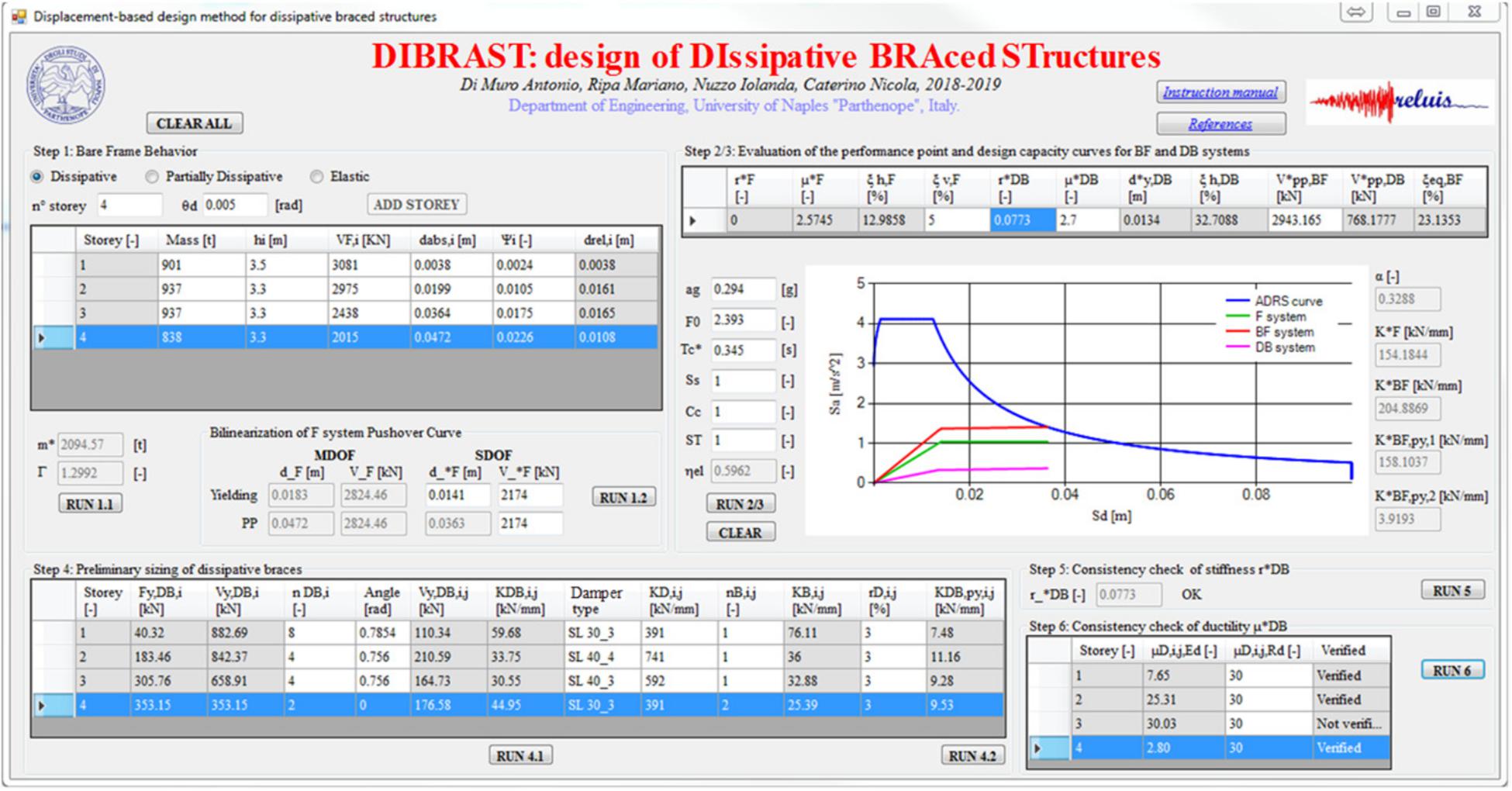
Figure 11. Damping braces design by means of DIBRAST.
After having identified F system behavior as dissipative, F properties at the target displacement θD = 0.5% have been defined. Namely, shear forces at each story and corresponding absolute displacements at target performance have been evaluated and inputted at step 1, along with first modal shape and seismic masses. Modal participation factor (Γ = 1.3) and equivalent mass (m∗ = 2095t) have been given as output for the determination of the F equivalent SDOF system capacity curve. At this point, the bilinear F system capacity curve has been constructed (Figure 12), determining base shear V = V = 2174 kN and top yielding displacement d = 0.014 m, while d is automatically determined by the tool (d = 0.036 m).
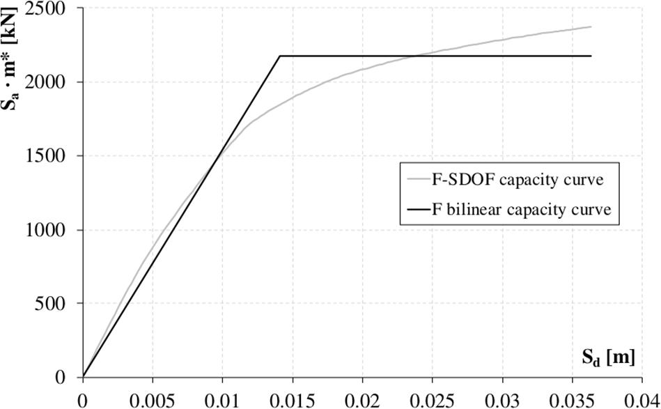
Figure 12. F system capacity curve.
According to step 2 of the design framework, the performance point is univocally determined once the viscous damping ratio of the equivalent F system, ductility, and post-yielding to elastic stiffness ratio of the dissipative system are defined. At this point, first trial values for the latter parameters have been initially considered equal to 3 and 0.4 respectively, whereas ξv,F has been set to 5%. At the same time, first trial equivalent base shear at performance point of the BF system has been specified greater than the F system one (i.e., 2500 kN > 2174 kN). Consequently, the equivalent damping ratio of the BF system has been automatically determined as an output by DIBRAST, and it is around 23%. Additionally, the final value of BF system at PP is V = 2943 kN. Seismic hazard parameters according to the Italian NTC2018 code in correspondence with the specific site and LS limit state are given in the input. At the end of step 3, DIBRAST provides the ADRS design curve for ξeq,BF, plotted together with F capacity curve and desired BF and DB capacity curves.
Knowing the equivalent damped brace system capacity curve, mechanical properties of the dissipative system in correspondence of each story can be read as an output of step 4. Thereby, after specifying the number of dampers at the i-th story, the tool provides the optimal stiffness (KDB,i,j) and yielding force (Vy,DB,i,j) of the j-th dissipative system at i-th story to converge on the desired result.
Dissipative braces composed of SL dampers arranged with steel diagonals are supposed to be installed at all levels. In particular, dissipative braces are installed only on perimetral frames along X direction, which resulted in them being more flexible than transversal ones. A total number of 8, 4, and 2 dampers are employed at first, second/third and fourth story, respectively (Figure 13). It is worth highlighting that the damped braces configuration is chosen in order to reduce the transmission of detrimental shear action in correspondence of columns. After defining the number of dampers at each story, the software provides the required mechanical properties at each braced bay. At this point, dimensioning of SLs and supporting braces can be performed and are addressed to the next section.
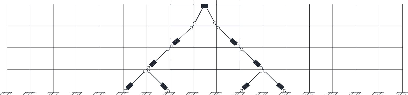
Figure 13. Dissipative braces configuration.
Successively, DIBRAST also provides required stiffness of supporting elements by solving Eq. 8. Thus, proper steel diagonals dimensions have been chosen from commercial catalogs according to required mechanical properties. In addition, SL devices post-yielding-to-elastic stiffness ratio (rD,i,j) has been set to 3%, obtaining the damped braces post-yielding stiffness distribution throughout the height.
After having designed the dissipative system, the equivalent post-yielding-to-elastic stiffnesses ratio r has to be checked to be consistent with the value initially set at step 2. Hence, the procedure is autonomously iterated until convergence is reached for r equal to 0.08. Finally, prompt ductility checks on each damper have been performed at the final step of the tool, considering SL ductility capacity equal to 30.
Knowing the required mechanical properties for each dissipative brace, the SL dampers have been designed through the design chart and the additional Shear Link Non-Linear Model tool presented in this paper.
Although various geometrical combinations may correspond to required mechanical properties, an attempt was made to limit the variability of dimensions to facilitate supply and on-site assembly operations. After selecting S275 steel grade and setting the SL yielding force (Fy) equal to the demanding shear force (Vy,DB,i,j) output from DIBRAST, the design chart of Figure 8 was adopted for the preliminary design of SL dampers. The value of Bw was restricted in the range of 300–400 mm, thus determining optimal tw values from the left-side plot of the design chart equal to 3 or 4 mm. Consequently, in the perspective of avoiding buckling phenomenon of the web, maximum height within stable behavior was detected from the central plot of the chart. Giving H2,lim as the upper bound, H2 equal to 110 mm was considered for all devices. Finally, knowing tw, Bw, and H2 for each device, SL elastic stiffness was determined from the right-side plot of the design chart. This approach led to the design of three types of SL devices, SL 30_3 for the first and last story, SL 40_4 at the second story, and SL 40_3 for the third one. The adopted SL geometries have been implemented in Shear Link Non-linear Model additional tool, thus further assessing the corresponding mechanical properties and accurately reading their values. Consequently, it is possible to determine the supporting brace section, knowing its required elastic stiffness in output from DIBRAST tool. Steel tubular elements have been selected from commercial catalogs and are characterized by a diagonal cross section and thickness dimensions in the range of 139.7 × 4 mm to 219.1 × 5.9 mm. Finally, the actual mechanical properties of dissipative braces, i.e., corresponding to real SL and brace-adopted design elements, have been determined and compared to required values output from DIBRAST (Table 1), evidencing a satisfactory matching.
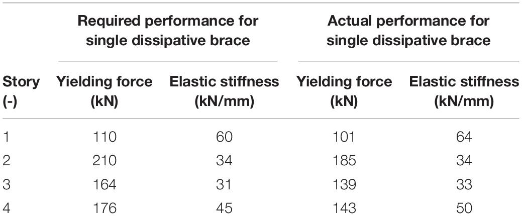
Table 1. Required vs. actual performance for single dissipative brace in horizontal direction.
In order to assess effectiveness of the proposed design approach, a static non-linear analysis was performed. In this way, SL devices with inelastic behavior were properly considered. In the 3D FEM model, damping braces have been modeled as non-linear Bouc-Wen link elements, adopting actual values of the mechanical parameters of dissipative braces (Table 1). The resulting pushover curve was converted into the equivalent SDOF system one, and the corresponding bilinear curve was determined. Comparing it to the desired retrofitted capacity curve (Figure 14), output from DIBRAST, a very satisfactory matching was observed. The desired DB capacity curve according to DIBRAST is shown as well, proving its adequateness in enhancing the as-built system and achieving the performance goal. At the performance point, the displacement demand on dampers resulted in containment in the range of 5–17 mm, which is thus lower than the displacement capacity of the SL dampers.
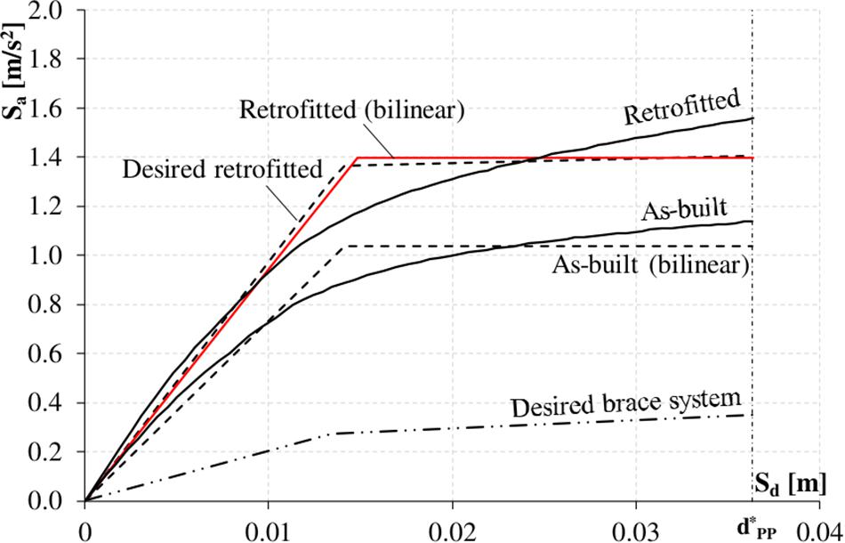
Figure 14. As-built and retrofitted capacity curves.
This paper has provided a comprehensive computer-aided seismic design procedure for structures equipped with hysteretic devices. As a matter of fact, despite several experimental works in literature highlighting the effectiveness of these devices for seismic hazard mitigation, their employment is not yet widespread due to a lack of design guidelines and prompt methodologies suitable for real structures. In fact, although various design procedures have been proposed, their quite articulated and iterative nature often make them unappealing for professional applications. For the above reasons, in the attempt of promoting the broad use of metallic hysteretic dampers as seismic protection systems, authors firmly believe in the need to support designers with a computer-aided tool able to drive them in the fulfillment of all steps of a specific displacement-based design procedure previously developed by the same authors. This specific methodology has been chosen because of its closed-form analytical nature, not involving further numerical structural analysis. Moreover, it is able to directly provide output-effective design parameters of dissipative system, resulting in it being suitable for professional applications. In this perspective, the DIBRAST—design of DIssipative BRAced Structures—tool has been developed, revoking the several phases of the framework. Required iterations are automated by the software, thus significantly reducing processing time. Input data are clearly identified and include bare frame properties along with the definition of the target displacement, to be given as a function of bare frame linear or non-linear behavior. In particular, modal and pushover analyses of the bare frame have to be performed at the beginning to determine its capacity curve as well as the first modal shape. Output effectively allow us to size the dissipative system, providing its mechanical properties, in terms of yielding force and elastic stiffness, are able to meet the performance objective. The computer-aided DIBRAST tool proposed herein is designed to be suitable for a wide variety of metallic hysteretic dampers. This work provides a complete how-to-use description of the software, which is freely available online.
Furthermore, to provide additional support to the designer in the geometrical characterization of hysteretic devices, analytical models, specifically developed for a particular damper, i.e., the SL, have been implemented in Visual Basic environment, thus developing Shear Link Non-Linear Model tool. This second software can be freely downloaded as well. The software delivers SL mechanical characteristics in terms of yielding force and elastic stiffness once the user inputs essential geometric dimensions, the type of material, and the boundary conditions. Although this allows us to get SL properties in an easy and prompt way, this tool still requires an initial blind design of the damper in order for it to be iteratively assessed. For this reason, authors further investigated on the influence of SL geometry on the mechanical characteristics of interest and, based on results of this study, new design charts have been proposed herein. In particular, the plots guide the designer in the detection of damper’s web optimal dimensions according to the desired yielding force, output from DIBRAST, also accounting for the possible web’s buckling phenomenon.
The effectiveness of the newly proposed design tools has been assessed with reference to the RC case study structure, located in central Italy, that was seismically upgraded by means of SL dampers. Using the DIBRAST tool, the optimal mechanical properties of damped braces at each of the four stories have been calculated. The overall performance objective was low structural damage thanks to the high dissipation provided by the hysteretic devices. Geometric details of each device were determined first using the newly proposed design charts and then through assessing them by means of the additional Shear Link Non-Linear Model tool. Finally, a non-linear static analysis of the retrofitted structure was performed, showing the achievement of the desired goals.
All datasets generated for this study are included in the article/supplementary material.
IN developed the seismic design approach in the Visual Basic environment with the assistance of the other two authors. FC applied the whole procedure to the case-study by means of the proposed softwares, then validated the outcomes through non-linear analyses. NC produced the charts for sizing the devices, and coordinated and supervised the overall work. All authors contributed to revising the manuscript and to approving the submitted version.
The research activity has been developed in the framework of the ReLUIS research project 2019–2021 funded by the Italian Department for Civil Protection. The above support is gratefully acknowledged.
The authors declare that the research was conducted in the absence of any commercial or financial relationships that could be construed as a potential conflict of interest.
The authors would like to thank Eng. Antonio Di Muro and Eng. Mariano Ripa for their great support and collaboration in the realization of the Visual Basic tools.
ATC (1996). Seismic Evaluation and Retrofit of Concrete Buildings, ATC-40. Redwood City, CA: Applied Technology Council.
Bergami, A. V., and Nuti, C. (2013). A design procedure of dissipative braces for seismic upgrading. Earthq. Struct. 4, 85–108. doi: 10.12989/eas.2013.4.1.085
Bergami, A. V., and Nuti, C. (2015). Experimental tests and global modeling of masonry infilled frames. Earthq. Struct. 9, 281–303. doi: 10.12989/eas.2015.9.2.281
Bergman, D. M., and Goel, S. C. (1987). Evaluation of Cyclic Testing of Steel-Plate Devices for Added Damping and Stiffness. Ann Arbor, MI: Department of Civil Engineering, University of Michigan.
Bozzo, L. M., and Barbat, A. H. (1999). Diseño Sismorresistente de Edificios. Técnicas Convencionales y Avanzadas (in Spanish). Barcelona: Editorial Reverte.
Bozzo, L. M., Cahís, X., and Torres, L. A. (1998). “Shear type energy dissipator for the protection of masonry infill walls,” in Proceedings of the 6th US National Conference on Earthquake Engineering, Seattle, WA.
Bozzo, L. M., Gonzales, H., Pantoja Medina, M., Munoz, E., and Ramirez, J. (2019). “Modeling, analysis and seismic design of structures using energy dissipators SLB,” in Proceedings of the International Symposium on Earthquake Engineering, Lima
Cahís, X. (2000). Desarrollo de un Nuevo Disipador de Energía Para Diseño Sismorresistente. Análisis Numérico y Validación Experimental de su Comportamiento. Ph.D. thesis, Universitat Politècnica de Catalunya, Barcelona.
Cahís, X., Bozzo, L. M., Torres, L., and Foti, D. (1997). “An energy dissipating device for seismic protection of masonry infill walls,” in Proceedings of the 8 Convegno Nazionale ANIDIS, Taormina.
Ciliento, F. (2019). Development of Seismic Design Procedures for Building Structures Equipped with SLB Metallic Hysteretic Devices. Ph. D. thesis, University of Naples Federico II, Naple.
Clark, P., Aiken, I., Kasai, K., Ko, E., and Kimura, E. (1999). “Design procedures for buildings incorporating hysteretic damping devices,” in Proceedings, 68th Annual Convention, Santa Barbara, California Structural Engineers Association of California, SEAOC, Santa Barbara, 355–371.
CSI and ETABS (2016). Structural Software for Building Analysis and Design. Berkeley, CA: Computers and Structures Inc.
CSI and SAP2000 (2019). Integrated Software for Structural Analysis and Design. Berkeley, CA: Computer and Structures Inc.
De Domenico, D., Impollonia, N., and Ricciardi, G. (2019). Seismic retrofitting of confined masonry-RC buildings: the case study of the university hall of residence in Messina. Italy Ingegneria Sismica. 36, 54–84.
Di Cesare, A., and Ponzo, F. C. (2017). Seismic retrofit of reinforced concrete frame buildings with hysteretic bracing systems: design procedure and behaviour factor. Shock Vib. 2017:2639361. doi: 10.1155/2017/2639361
Di Cesare, A., Ponzo, F. C., and Nigro, D. (2014). Assessment of the performance of hysteretic energy dissipation bracing systems. Bull. Earthq. Eng. 12, 2777–2796. doi: 10.1007/s10518-014-9623-z
Dwairi, H. M., Kowlsky, M. J., and Nau, J. M. (2007). Equivalent damping in support of direct displacement-based design. Earthq. Eng. 11, 512–530. doi: 10.1080/13632460601033884
EN 15129 (2009). European Standard, Anti-seismic devices. Brussels: European Committee for Standardization.
Franchioni, G., Severn, R. T., and Bairrao, R. (2001). Experimental Investigations on Semiactive and Passive Systems for Seismic Risk Mitigation. Report No. 7, ECOEST2 & ICONS.
Greco, F., Rosati, L., Serino, G., and Vaiana, N. (2018). A mixed explicit-implicit time integration approach for nonlinear analysis of base-isolated structures. Ann. Solid Struct. Mech. 10, 17–29. doi: 10.1007/s12356-017-0051-z
Hurtado, F. (2006). Propuesta de Disipador Genérico “SL” Para Edificios y su Diseño Sismorresistente. Ph. D. thesis, Universitat Politécnica de Catalunya, Barcelona.
Hurtado, F., and Bozzo, L. M. (2005). Un disipador Shear Link (SL) generalizado para diseño sismorresistente (in Spanish). Hormigón Y Acero. 235, 53–68.
Hurtado, F., and Bozzo, L. M. (2008). “Numerical and experimental analysis of a shear-link energy dissipator for seismic protection of buildings,” in Proceedings of the 14th World Conference on Earthquake Engineering, Beijing.
Javanmardi, A., Ibrahim, Z., Ghaedi, K., Ghadim, H. B., and Hanif, M. U. (2019). State-of-the-art review of metallic dampers: testing, development and implementation. Arch. Comput. Methods Eng.
Kelly, J. M., Skinner, R. I, and Heine, A. J. (1972). Mechanisms of energy absorption in special devices for use in earthquake resistant structures. Bull. N. Z. Soc. Earthq. Eng. 5, 63–88.
Kim, J., and Choi, H. (2004). Behavior and design of structures with buckling-restrained braces. Eng. Struct. 26, 693–706. doi: 10.1016/j.engstruct.2003.09.010
Kobori, T., Miura, Y., and Fukuzawa, E. (1992). “Development and application of hysteresis steel dampers,” in Proceedings of the 10th World Conference on Earthquake Engineering, Rotterdam, 2341–2346.
Losanno, D., Londono, J. M., Zinno, S., and Serino, G. (2018). Effective damping and frequencies of viscous damper braced structures considering the supports flexibility. Comput. Struct. 207, 121–131. doi: 10.1016/j.compstruc.2017.07.022
Losanno, D., Spizzuoco, M., and Serino, G. (2015). An optimal design procedure for a simple frame equipped with elastic-deformable dissipative braces. Eng. Struct. 101, 677–697. doi: 10.1016/j.engstruct.2015.07.055
Losanno, D., Spizzuoco, M., and Serino, G. (2019). Design and retrofit of multi-story frames with elastic-deformable viscous damping braces. J. Earthq. Eng. 23, 1441–1464. doi: 10.1080/13632469.2017.1387193
Mazza, F. (2019a). A plastic-damage hysteretic model to reproduce strength stiffness degradation. Bull. Earthq. Eng. 17, 3517–3544. doi: 10.1007/s10518-019-00606-3
Mazza, F. (2019b). A simplified retrofitting method based on seismic damage of a SDOF system equivalent to a damped braced building. Eng. Struct. 200:109712. doi: 10.1016/j.engstruct.2019.109712
Mazza, F., and Vulcano, A. (2015). Displacement-based design procedure of damped braces for the seismic retrofitting of r.c. framed buildings. Bull. Earthq. Eng. 13, 2121–2143. doi: 10.1007/s10518-014-9709-7
Nuzzo, I., Losanno, D., and Caterino, N. (2019). Seismic design and retrofit of frame structures with hysteretic dampers: a simplified displacement-based procedure. Bull. Earthq. Eng. 17, 2787–2819. doi: 10.1007/s10518-019-00558-8
Nuzzo, I., Losanno, D., Caterino, N., Serino, G., and Bozzo Rotondo, L. M. (2018). Experimental and analytical characterization of steel shear links for seismic energy dissipation. Eng. Struct. 172, 405–418. doi: 10.1016/j.engstruct.2018.06.005
Nuzzo, I., Losanno, D., Serino, G., and Bozzo, L. M. (2015). “Simplified nonlinear analysis: application to damper-braced structures,” in Proceedings of the 15th International Conference on Civil, Structural and Environmental Engineering Computing, Prague.
Ponzo, F. C., Di Cesare, A., Lamarucciola, N., and Nigro, D. (2019). Seismic design and testing of post-tensioned timber buildings with dissipative bracing systems. Front. Built Environ. 5, 1–13. doi: 10.3389/fbuil.2019.00104
Shin, M. H., and Sung, W. P. (2005). A model for hysteretic behaviour of rhombic low yield strength steel added damping and stiffness. Comput. Struct. 83, 895–908. doi: 10.1016/j.compstruc.2004.11.012
Tsai, K. C., Chen, H. W., Hong, C. P., and Su, Y. F. (1993). Design of steel triangular plate energy absorbers for seismic-resistant construction. Earthq. Spectra 9, 505–528. doi: 10.1193/1.1585727
Vaiana, N., Sessa, S., Marmo, F., and Rosati, L. (2018). A class of uniaxial phenomenological models for simulating hysteretic phenomena in rate-independent mechanical systems and materials. Nonlinear Dyn. 93, 1647–1669. doi: 10.1007/s11071-018-4282-2
Vaiana, N., Sessa, S., Marmo, F., and Rosati, L. (2019a). An accurate and computationally efficient uniaxial phenomenological model for steel and fiber reinforced elastomeric bearings. Compos. Struct. 211, 196–212. doi: 10.1016/j.compstruct.2018.12.017
Vaiana, N., Sessa, S., Marmo, F., and Rosati, L. (2019b). Nonlinear dynamic analysis of hysteretic mechanical systems by combining a novel rate-independent model and an explicit time integration method. Nonlinear Dyn. 98, 2879–2901. doi: 10.1007/s11071-019-05022-5
Watanabe, A., Hitomi, Y., Saeki, E., Wada, A., and Fujimoto, M. (1988). “Properties of brace encased in buckling-restraining concrete and steel tube,” in Proceedings of 9 th World Conference on Earthquake Engineering, Tokyo–Kyoto.
Keywords: computer-aided design approach, hysteretic dampers, braced structures, SL devices, design charts
Citation: Nuzzo I, Ciliento F and Caterino N (2020) DIBRAST: A Computer-Aided Seismic Design Procedure for Frame Structures Equipped With Hysteretic Devices. Front. Built Environ. 6:13. doi: 10.3389/fbuil.2020.00013
Received: 16 December 2019; Accepted: 31 January 2020;
Published: 21 February 2020.
Edited by:
Dario De Domenico, University of Messina, ItalyReviewed by:
Antonio Di Cesare, University of Basilicata, ItalyCopyright © 2020 Nuzzo, Ciliento and Caterino. This is an open-access article distributed under the terms of the Creative Commons Attribution License (CC BY). The use, distribution or reproduction in other forums is permitted, provided the original author(s) and the copyright owner(s) are credited and that the original publication in this journal is cited, in accordance with accepted academic practice. No use, distribution or reproduction is permitted which does not comply with these terms.
*Correspondence: Iolanda Nuzzo, bnV6em9AaXRjLmNuci5pdA==
Disclaimer: All claims expressed in this article are solely those of the authors and do not necessarily represent those of their affiliated organizations, or those of the publisher, the editors and the reviewers. Any product that may be evaluated in this article or claim that may be made by its manufacturer is not guaranteed or endorsed by the publisher.
Research integrity at Frontiers
Learn more about the work of our research integrity team to safeguard the quality of each article we publish.