Corrigendum: Numerical Simulation of the Dynamic Response of Ballasted Track Overlying a Tire-Reinforced Capping Layer
 Qideng Sun
 Buddhima Indraratna2‡
- 1Coffey Services Australia Pty Ltd, Chatswood, NSW, Australia
- 2Transport Research Centre, University of Technology, Sydney, NSW, Australia
- 3Ecoflex International Pty Ltd, Avoca Beach, NSW, Australia
This paper describes a 3D finite element (FE) model developed to understand the dynamic response of a ballasted track in which the underlying capping layer is reinforced using recycled rubber tires. Track deflection, the lateral spreading of ballast and vertical stress transmitted from the capping layer to the subgrade are discussed by considering the effect of reinforcement provided by these infilled tires. In this respect, the capping layer is confined and has improved damping properties. The cellular structure of the rubber tire assembly can radially confine the infilled materials, and thus reduce excessive lateral spreading and vertical displacement that would otherwise occur in a conventional track. At the same time the tire and gravel composite layer acts like a stiff but flexible “mattress” that controls the stress transmitted to the underlying subgrade while making it more uniform. Typical soft and stiff subgrade materials were used to investigate the dynamic response of track, and the stress paths of subgrade at different depths have been studied. It is noted that the effect of the tire assembly on the stress distribution within the subgrade decreases with depth, and the tire-reinforced track deflects less than its unreinforced counterpart at any given train speed.
Introduction
The need for long-term performance of rail infrastructure has been increasingly higher in the past decades as rail tracks systems supporting the transport network are expected to withstand higher speeds and larger loads. Heavier and faster trains could exert higher dynamic wheel loads on track, and therefore a soft subgrade may experience higher repeated stresses which may lead to excessive deformation and progressive shear failure. Moreover, under larger dynamic loads (e.g., rail freight traffic), an existing track may degrade further and faster due to excessive track deformation and the lateral displacement of ballast requiring more frequent maintenance. Geocells offer a plastic cellular confinement system with a honeycomb-like structure that can be filled with an appropriate granular material, and has been successfully used in ground improvement applications including transport infrastructure (Leshchinsky and Ling, 2012, 2013; Indraratna et al., 2015). During loading, additional confinement is provided by the geocells as they mitigate the granular mass of subballast from spreading laterally, increase the rigidity of the infill, and improve the load-carrying capacity (Zhang et al., 2010; Leshchinsky and Ling, 2012; Sitharam and Hegde, 2013), and thereby improving the overall track performance. Similarly to geocells, scrap tires can provide additional cellular confinement to the infill materials and also improve the strength and stiffness of a railway track. Indraratna et al. (2017) proposed a rubber tire based capping layer for railway track where one sidewall is removed and the tire is then filled with gravel; a geotextile can be placed between the rubber tire and the ground as a separator. Plate load tests (Indraratna et al., 2017) and prototype process simulation carried out by Indraratna et al. (2018) revealed that a tire cell has three primary engineering benefits: (i) the confinement provided by the cellular assembly can increase the stiffness of the contained aggregate, which then reduces lateral spreading and vertical deformation within the capping and ballast layers; (ii) the tires and gravel composites allow a reduced and more uniform stress distribution to the subgrade; and (iii) tire cells can enhance the damping properties of the system, and thus its ability to attenuate dynamic forces imposed by rail traffic. However, since the dimensions are limited by the size of the experimental facility (i.e., 800 × 600 × 600 mm), a light vehicle tire having a diameter of 560 mm was tested. In reality, heavy vehicle tires with a diameter of about 1 m are preferred because they have much larger stiffness compared with car tires. The tire-reinforcement is very similar to geocell reinforcement. The benefits of geotextile and geogrid reinforcement are: (i) geotextile reinforcement restricts the lateral deformation of the soil; (ii) strength improvement of the reinforced soil is attributed to openings in the geogrid that causes interlocking; and (iii) reinforcement effect in undrained condition is an increase in cohesion and the effect in drained condition is an increase in internal friction.
Theoretical and numerical models have been developed by numerous studies to better understand the amplitude of vibration of the track-ground system during train passage. The approaches adopted including: (i) analytical models (Kenney, 1954; Krylov, 1995; Sheng et al., 1999; Kaynia et al., 2000; Madshus and Kaynia, 2000; Kargarnovin and Younesian, 2004; Kargarnovin et al., 2005; Picoux and Le Houedec, 2005; Takemiya and Bian, 2005; Karlstrom and Bostrom, 2006); (ii) numerical models based on the finite element (FE) and boundary element (BE) methods (Hall, 2003; Sheng et al., 2003, 2005; Yang et al., 2003; Kouroussis et al., 2009; Lombaert and Degrande, 2009; Costa et al., 2010, 2012; Ju et al., 2010; El Kacimi et al., 2013; Shih et al., 2016, 2017). In design of railway embankments, simplified theoretical and empirical methods are typically used by assuming a homogeneous half-space for all the track layers, without considering the individual layer properties (e.g., Okabe, 1961; Heath et al., 1972; AREA, 1996). Multilayer track models, such as ILLITRACK (Robnett et al., 1975), GEOTRACK (Chang et al., 1980), and KENTRACK (Huang et al., 1986) were developed to analyze stresses in the track and subgrade. These models were based on the assumption that substructure materials are purely elastic and this will lead to inaccurate prediction. Recently, a finite element 3D model has been developed to investigate the load transfer mechanism between tires and infill gravels under static loading (Indraratna et al., 2017). It was reported that the confining effect causes the tire and gravel infill composite to act as a stiff but flexible “mattress” that can effectively reduce the amplitude of stresses transmitted to the subgrade.
In this paper, a 3D FE dynamic model is developed to simulate both the track super and substructure and rail traffic subjected to moving point loads that apply onto the beam elements representing the rail system. A realistic scenario to validate the 3D FE model is the well-documented case study of ground vibrations generated by X2000 trains at the Ledsgard site in Sweden (Hall, 2003). Then, for simplicity and ease of simulation, another track with a simpler substructure is adopted, and a typical three-wagon Australian freight train is simulated accordingly. The effect of tires on infilled gravels is simulated by changing material properties of capping, namely, Young's modulus (Ec), apparent drained cohesion (Cc), and damping ratio (ξ). The friction angle of the granular mass was kept constant.
Modeling the Moving Vehicle Problem
To model the dynamic response induced by a moving train, separate models may be used to represent the vehicle and the track/ground system; elements with rigid bodies can be used for vehicle components, such as car bodies, bogies, and wheelsets, while the primary and secondary suspensions can be modeled by the springs and dampers that connect to the rigid bodies. With a moving vehicle problem, the loads depend on the dynamic response of the vehicle and the track system, so a user-defined subroutine is often used to combine both programs despite having significant impact on the computational time. However, two other approaches can be adopted in ABAQUS to integrate both systems one is by using the large (finite) sliding contact model in ABAQUS (Hibbitt, Karlsson & Sorensen, Inc., 2014) to connect the vehicle and track/ground system, and the other is calculating the moving load by specifying the nodal forces that correspond to the moving load as a function of time history. While the latter approach omits the vehicle dynamics, it can greatly reduce the associated computational time and thus adopted in this study as shown in Figure 1A.
FIGURE 1
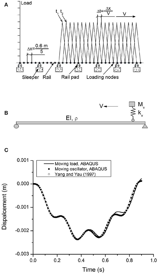
Figure 1. (A) Description of the loading model used in the Finite Element Model; (B) moving oscillator with a simply support beam; and (C) vertical displacement at the midpoint of the beam using different loading procedures.
In this approach, the rail is essentially built up from nodes and beam elements. In this paper the nodes representing the rail are referred to as loading nodes, and every fifth loading node is connected to the elements forming the sleepers (ties) by spring elements as shown in Figure 1A. Since the spacing between the sleepers is 0.6 m, the spacing between the loading nodes is 0.12 m. Point loads are applied at the loading nodes and for a given speed (V), the loads can be thought of as triangular pulses distributed between three nodes, that can be moved from node to node by a time step (Δt) given by Δt = Δx/V, where Δx is the node spacing as shown in Figure 1A.
This loading model is similar to the procedure described earlier by Hall (2003). It should be noted that the “rail” is only connected to the rest of the finite element model by the loading nodes in the “sleepers.” The load on the “rail” is therefore only transferred to the rest of the model through the “sleepers.” This is very similar to reality. It is acknowledged that numerical models have been developed where no beam elements were used. Load distributions was calculated for application to the sleepers (e.g., Feng et al., 2019). Comparison for a one-point load was made between two load models and it was indicated that the two loading models gave approximately the same results (Hall, 2003). This approach has been tested on a simple moving vehicle-bridge interaction problem (Figure 1B). The large (finite) sliding contact model that simulates the moving oscillator in ABAQUS (Hibbitt, Karlsson & Sorensen, Inc., 2014) is also adopted for comparison. The material parameters for the beam are: Young's modulus E = 2.87 GPa, Poisson's ratio ν = 0.2, second moment of area I = 2.94 m4, mass per unit length ρA = 2,303 kg/m. The suspension stiffness (kv) is 1,595 kN/m, and the mass (Mv) is 5,750 kg. The vehicle speed (V) is 100 km/h and the length of the beam L = 25 m.
The dynamic response of the moving load and moving oscillator problems obtained using ABAQUS is compared to the numerical solution obtained by Yang and Yau (1997) in Figure 1C. The displacements obtained for the beam agree with the analytical result, and the difference in the beam response introduced by the dynamics of the spring mass is insignificant compared to the result for a moving load. Hence, in this study the moving load procedure has been considered.
Case Study-3D FE Model for Ledsgard Track
Having established a method for simulating a moving vehicle in the FE model, a 3D model of the vehicle-track-ground system has been developed using ABAQUS 6.14-2. To ensure the modeling process can provide reliable outcomes, a case study that is well-documented in the literature (Hall, 2003) has been used to ascertain the reliability and accuracy of the model. The FE mesh of the track and ground at the Ledsgard site is shown in Figure 2A. This FE model makes use of symmetry in the x-y plane and fixed boundaries are used. The 3D model measures 104 m long × 40 m wide × 30 m high and consists of 242,962 elements. The length of the model required to achieve convergence depends on the load speed, so longer models are needed if the load speed approaches or exceeds the critical speed. In this instance the model is 104 m long, which is sufficient for convergence (Shih et al., 2016). If the model is wide enough there is little benefit in using absorbing elements at the boundaries. This is because a damping model with a large enough mass-proportional term allows the energy to dissipate and avoids any reflections interfering with the results (Shih et al., 2016). Hence, 30 m deep by 40 m wide FE mesh with Rayleigh damping model is used in this study. The damping ratio in the Rayleigh damping model is frequency dependent, so for the parameters adopted in the damping model, a damping ratio of about 4% (Table 1) in the frequency range of interest is obtained, as suggested by Hall (2003).
FIGURE 2
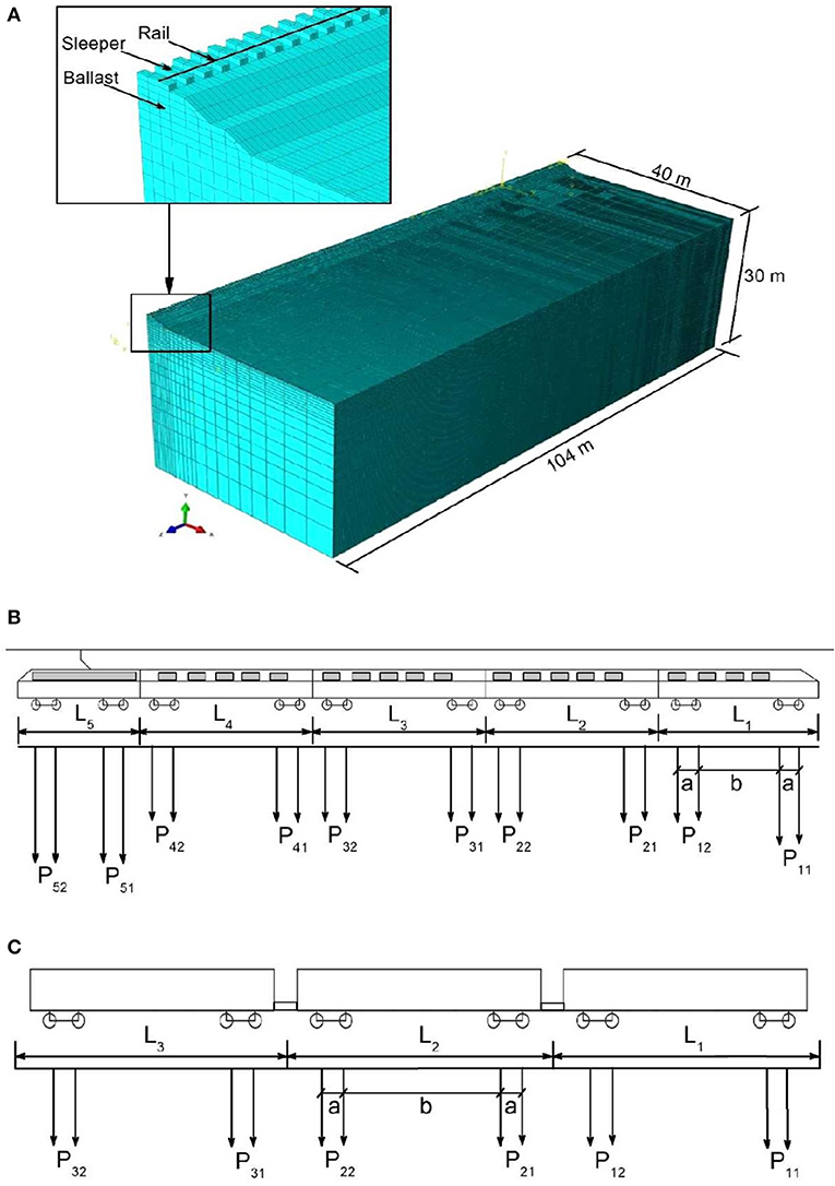
Figure 2. (A) 3D FE track/ground model; (B) schematic diagram of modeled trains: the X2000 high speed train; and (C) idealized three-wagon Australia freight train.
TABLE 1
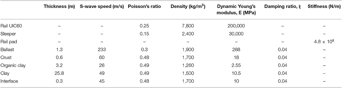
Table 1. Track and ground properties adopted for FE model for the site at Ledsgard (Hall, 2003; Sayeed and Shahin, 2016).
The mesh of the embankment and ground are mainly composed of hexahedral 8-noded elements (C3D8). The rail is modeled with Timoshenko beam elements (B31) that include the effects of shear deformation and rotational inertia. While both of these effects are ignored in standard Euler-Bernoulli beam theory, they are better suited to modeling thick or slender beams. The beam is given the geometry and properties of regular railway rails (UCI60), and to represent the rail pads, linear springs with a vertical stiffness 4.8 × 10⁸ N/m connect the rail to each sleeper. Discrete sleepers with a spacing of 0.6 m are included; they have a half-length of 1.25 m, a height of 0.2 m, a mass density of 2,400 kg/m3, a Young's modulus of 3 × 10¹⁰ N/m2 and Poisson's ratio of 0.15. The ballast is embedded into the upper ground layer to a depth of 0.3 m. A 0.3 m thick interface layer is laid underneath the ballast. The smallest element is 0.25 m near the track, but it gradually increases in size with a stretch factor of 1.2 in the horizontal direction outside the width of the track, and in the vertical direction for the clay layer. The total number of degrees of freedom in the model is 806,913. The soil properties for the case study are available from various in-situ tests, such as seismic core penetration testing, cross-hole tests, and spectral analysis of surface waves (Hall, 2003; Costa et al., 2010). There are five soil layers, namely the ballast, interface, dry crust, organic clay, and clay. The material properties used for the various layers are listed in Table 1 (Hall, 2003; Sayeed and Shahin, 2016). The results for a set of moving axle loads are presented, but the surface roughness excitation is omitted. The geometry of the high speed train X2000, is reported in more detail by Kouroussis et al. (2014) and represented in Figure 2B and Table 2, but a full train set consisting of a driving trailer vehicle, three passenger carriages, and a locomotive is considered for the current analysis.
TABLE 2
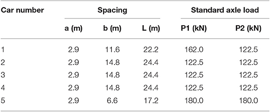
Table 2. Geometry and axle loads of the X2000 high speed train (Kouroussis et al., 2014).
The time-history response of track displacement during the passage of train at speeds of 70 and 200 km/h are calculated at the track center, and then the results are compared to the corresponding field measurements, as shown in Figures 3A,B (downward negative). Note that at 70 km/h, only quasi-static deflection appears when the load moves over the point of concern, but an oscillatory response occurs at a higher speed of 200 km/h. The FE predictions agree reasonably well with the field measurements, which proves that the FE modeling process in this study is reliable and can be used with confidence to predict the track behavior under a moving train load. To investigate the effect that material elasto-plasticity has on the dynamic track response, the traditional Mohr-Coulomb model is adopted to simulate ballast with a friction angle ϕ = 50°. The model predictions in terms of (a) track deflection at the midpoint of track, (b) vertical stress transmitted from ballast to the interface, and (c) lateral displacement of ballast, are compared to the predictions made with an elastic model at a speed of 70 km/h. Figures 3C–E shows the differences in predictions based on the elastic and the Mohr-Coulomb model. The latter predicts greater track deflection, larger vertical stress and greater ballast spreading. This occurs because the elasto-plastic analysis allows plastic deformation to develop. So in the following analysis the Mohr-Coulomb elasto-plastic model is considered to model the track materials.
FIGURE 3
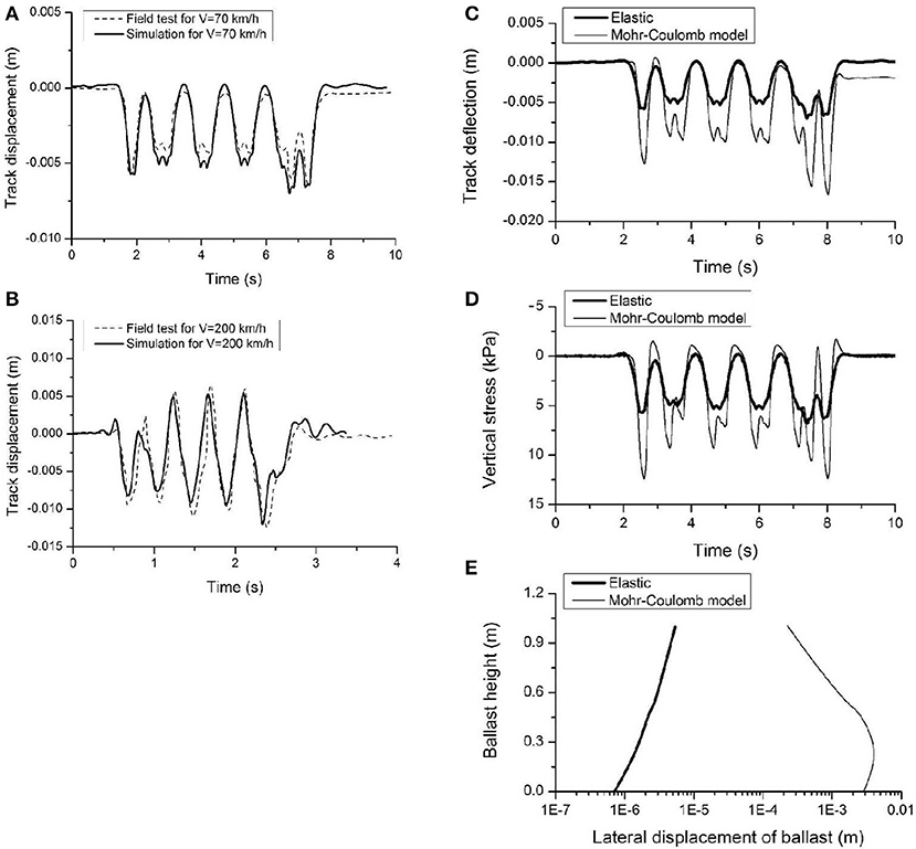
Figure 3. (A) Comparison between FE simulation and field measurement of track response for X2000 train with a speed of 70 km/h; (B) with a train speed of 200 km/h; (C) comparison of predictions with different ballast models for track deflection at the midpoint of the track; (D) vertical stress transmitted from ballast to interface; and (E) lateral displacement of ballast.
Modeling Tire-reinforced Capping Layer
To study the effects induced by rubber tires in the capping layer, an FE model with a simplified profile is used (Figure 4A). Traditional capping layer material (i.e., crushed basalt) is modeled with Young's modulus equals to 140 MPa, frictional angle equals to 38° and dilation angle equals to 5°. The model consists of a 0.35 m thick ballast layer, and a 0.15 m thick capping layer founded on 30 m thick ground. A train with three typical freight wagons has been modeled in this analysis to mimic Australian rail freight traffic (ARTC, 2011). Details of the freight train are shown in Figure 2C and Table 3. A 25 t axle load is applied in the model, and the train runs along the rail in the positive direction of the z axis at various speeds (V).
FIGURE 4
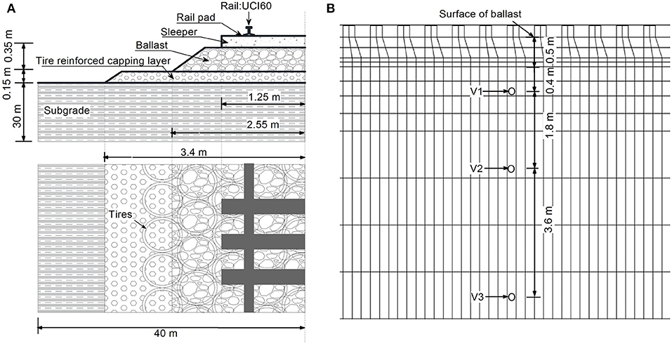
Figure 4. (A) Cross section of the track and (B) indication of stress observation points.
TABLE 3
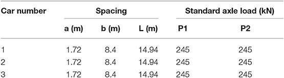
Table 3. Geometry and axle loads of the idealized three-wagon Australian freight train (ARTC, 2011).
Laboratory tests revealed that the cylindrical structure of a tire confines the infill material and reduces its lateral displacement (Indraratna et al., 2017), whereas the vertical load could produce circumferential tensile strain in the tire that would induce more confining stress Δσ3′ from the rubber tire to the capping gravels. By assuming that the internal friction angle of gravel for the reinforced sample remains constant (ϕ = 38°), the apparent cohesion Cc can be used to account for the increasing strength of the tire cell (Bathurst and Karpurapu, 1993) and can be readily incorporated in ABAQUS:
where ϕ is the friction angle of the infill material. The increased confining stress Δσ3′, can be estimated by the following equation (Bathurst and Karpurapu, 1993).
where Mt (=45 MN/m) is the tensile stiffness of the tire, D (=1 m for a truck tire) is the initial diameter of the tire, and εa is the axle strain of the sample. Bathurst and Karpurapu (1993) used a similar method to account for the increasing strength of geocell reinforcement. In the 3D FE model, two values of Cc (i.e., 5 and 46 kPa corresponding to Δσ3′ of 4.5 and 45 kPa at εa = 0.01 and 0.1%, respectively) are used to study the increase of additional confinement.
According to Indraratna et al. (2018), there is ~15% improvement in the damping ratio of the sample with a tire compared to the sample without a tire. A viscous damping model based on Rayleigh damping, is used in the 3D FE model. Rayleigh damping is based on the two parameters α and β, both of which allow the damping matrix C to be determined from the mass and stiffness matrix M and K (Hibbitt, Karlsson & Sorensen, Inc., 2014):
This allows the equivalent loss factor η or damping ratio ξ to be obtained as a function of frequency as (Hibbitt, Karlsson & Sorensen, Inc., 2014):
where ω is the circular frequency where the loss factor η applies. The circular frequency is usually selected to correspond to the resonance frequency in the system because the damping resonances are important. Rayleigh damping (stiffness-proportional) that is equivalent to Kelvin-Voigt damping can be obtained by setting α equal to zero (Connolly et al., 2013), while mass-proportional Rayleigh damping can be obtained by setting β equal to zero (El Kacimi et al., 2013). Combined Rayleigh damping can be obtained by fitting the damping ratio to that measured at the site, as proposed by Hall (2003). In the 3D FE model, damping ratios ξ = 0.09 and 0.18 are used with and without tires. The effect that rubber tires have on the stiffness of the capping layer is reflected by Young's modulus variation, i.e., 220 and 500 MPa were used in the 3D model to study the increase in Young's modulus. The values of the model parameters are shown in Table 4 (Indraratna et al., 2017, 2018).
TABLE 4
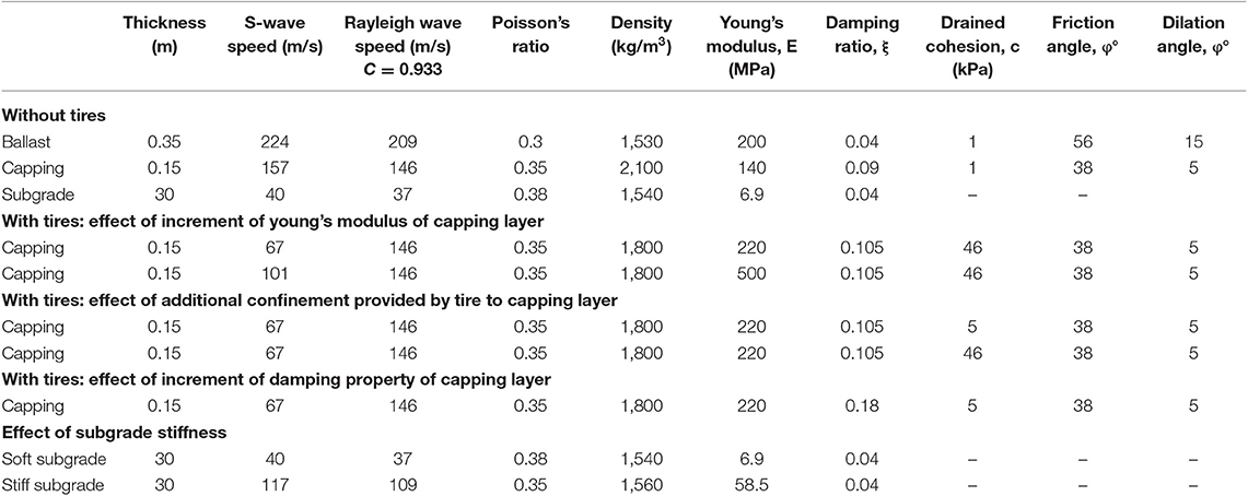
Table 4. Track and ground properties used to investigate the effect of rubber tire (Indraratna et al., 2017, 2018).
Model Predictions
Dynamic Track Response
A series of simulations have been carried out to determine how the tires improve track stiffness, and how they affect the increment of additional confinement and damping ratio. To compare the results, each scenario has been analyzed with and without tire reinforcement for comparison. During this simulation, track deflection, lateral displacement of the ballast layer and the vertical stress transmitted from the capping layer to the subgrade layer were observed.
Deflections at the midpoint of the track are plotted in Figure 5, and it shows that with tire reinforcement the track experiences less deflection than that without tires. Figure 5A shows that the increment of Young's modulus in the capping layer only has a marginal effect on track deflection, but as drained cohesion increases, the track deflection decreases (Figure 5B). Moreover, incremental increases in damping in the capping layer provided by the inclusion of tires seems to have minimal influence in the track deflection even though the damping ratio increases from 0.09 to 0.18 (Figure 5C).
FIGURE 5
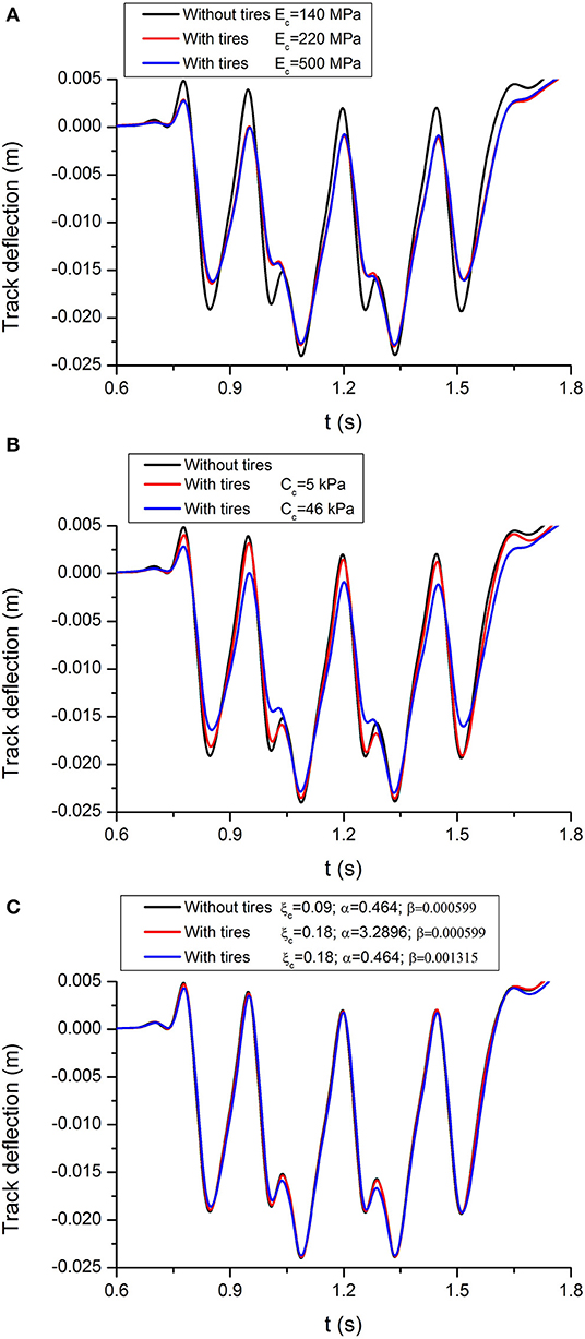
Figure 5. Track deflection with different values of model parameters for capping layer: (A) Young's modulus, (B) apparent drained cohesion, and (C) damping ratio.
Figure 6 shows how tire reinforcement influences the lateral displacement of ballast particularly at the shoulder location as shown in Figure 6A. The results indicate that rubber tires could help to reduce the lateral displacement of ballast, and with the increase of Young's modulus and cohesion in the capping layer, the ballast layer experiences less lateral displacement, as shown in Figures 6B,C. For instance, at the crest of the ballast layer a reduction in 0.6% is observed with the inclusion of tires (Figure 6B). This improvement in the stiffness of the capping layer by additional confinement by tires also reduces lateral displacement of the capping layer and ballast layer and reduces the vertical displacement.
FIGURE 6
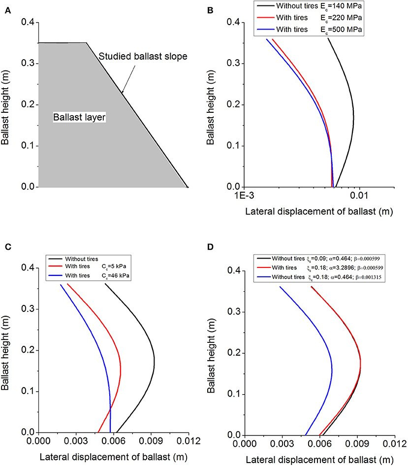
Figure 6. Predicted lateral displacement of ballast with different values of model parameters for capping layer: (A) ballast profile, (B) Young's modulus, (C) apparent drained cohesion, and (D) damping ratio.
Rayleigh damping is based on the parameters α and β, which allow the damping matrix to be determined from the mass and stiffness matrices. In this study a constant damping ratio (ξ) of 0.09 is assumed in the model without reinforcement; the corresponding parameters α = 0.464 and β = 5.99 × 10⁻⁴ at 10 Hz. The damping ratio ξ, of 0.18 is used for the model with reinforcement. The stiffness-proportional Rayleigh damping is studied by allowing α to equal 0.464. Hence, the increment of ξ from 0.09 to 0.18 is reflected by an increment of β from 5.99 × 10⁻⁴ to 1.315 × 10⁻³. Conversely, mass-proportional Rayleigh damping can be obtained by setting β equal to 5.99 × 10⁻⁴, this results in α = 3.2896 and 0.464, which corresponds to ξ = 0.18 and 0.09, respectively. Figure 6D shows that the value of β that corresponds to the stiffness-proportional Rayleigh damping has an apparent influence on the lateral displacement of ballast.
Figures 7A–C shows that rubber tires can reduce the pressure transmitted from the capping layer to the subgrade layer, but the variation in Young's modulus and the damping ratio have negligible effect on the vertical stresses. This reduction in vertical stress in the capping layer incorporating rubber tires is due to the additional confinement provided by the rubber membrane which also reduces the vertical stress, as shown in Figure 7B. Intuitively, the confining effect causes the tires and gravel infill composite to act as a stiffer, flexible “mattress” which results in a reduced and more uniform stress distribution.
FIGURE 7
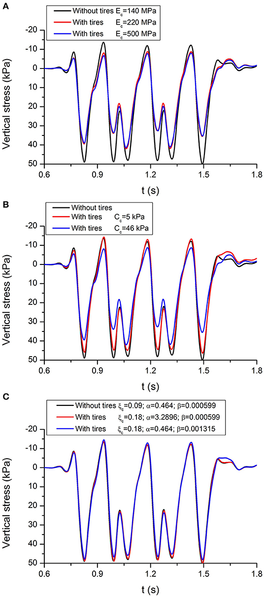
Figure 7. Predicted vertical stress transmitted from capping layer to subgrade with different values of model parameters for capping layer: (A) Young's modulus, (B) apparent drained cohesion, and (C) damping ratio.
Effect of Different Types of Subgrade
The dynamic response of the track-ground system has been investigated considering two typical subgrades, one with soft soil (i.e., fat clay of the Monroe dam, E = 6.9 MPa; Duncan et al., 1980) and the other with stiff soil (i.e., low density sand, E = 58.5 MPa; Al-Shayea et al., 2003). The properties of the subgrades are summarized in Table 4. Two different scenarios (i.e., with and without reinforcement) are modeled with each type of subgrade. Model properties for reinforced capping layer are Ec = 220 MPa, Cc = 5 kPa and ξ = 0.18 with α = 0.464 and β = 1.315 × 10⁻³. Figure 8A shows deflection obtained at the track midpoint with different subgrades. As expected, the track experiences much less deflection on a stiff subgrade than on a softer subgrade. For example, at a train speed of 216 km/h the maximum deflection of the unreinforced track with soft and stiff subgrade is 0.024 and 0.003 m, respectively, which is because track built on soft subgrade usually yields high ground vibrations at low train speed than those founded on stiff subgrade. The reduction of settlement for a track substructure reinforced with tires is more obvious for the cases where the track is supported by a soft subgrade material. For instance, while a reduction of 5.3% is observed for soft subgrade case, no discernible difference was observed for the stiff subgrade (Figure 8A).
FIGURE 8
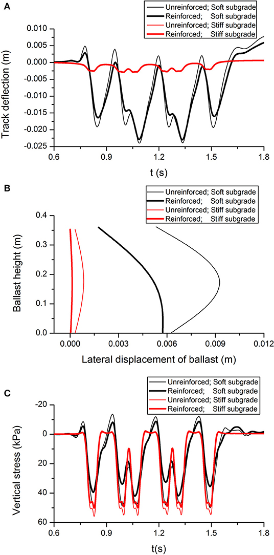
Figure 8. Dynamic response of track with different subgrade (A) track deflection, (B) lateral displacement of ballast, and (C) vertical stress of subgrade.
One obvious advantage of the tire is its ability to redistribute the stress and reduce the magnitude of the subgrade stresses as shown in Figure 8C. Unlike the unreinforced track, the peak stress of reinforced track decreased by ~30.9 and 10.6% with soft and stiff subgrade, respectively. It is noteworthy that the vertical stress on a stiff subgrade is higher than on a soft subgrade. This is probably because the lower damping ratio of the stiffer material leads to a higher resistance. Intuitively, lowering the vertical stress on the subgrade reduces the vertical and lateral displacement of the track. Using rubber tires in the capping layer decreases lateral spreading by 47.3 and 83.9% with soft and stiff subgrade, respectively (Figure 8B).
Stress Paths in Subgrade
The dynamic stress induced by train passage in the track substructure is one of the most important parameters in railway design and maintenance (Bian et al., 2014). Determining the intensity of dynamic stress at the ground surface and its attenuation in the subgrade is crucial to proper design. The dynamic stress-time history curves and stress paths of the models are compared with and without rubber tires. There are three observation points in the mid cross-section of the model at depths of 0.4, 2.2, and 5.8 m, these points are V1, V2, and V3, as shown in Figure 4B. Figure 9 shows a comparison of the dynamic soil stress-time history curves under a load of three moving carriages; they consist of the vertical stress Syy and shear stress Syz at points V1, V2, and V3. It is important to note that the vertical stress and shear stress in the subgrade decrease with depth. It can be observed that the tire reinforcement can reduce the vertical and shear stress, but the reduction is more evident for shallow depths. In fact, for V3 point located at 5.8 m the reduction is marginal. Figure 9A also shows that the train axles are not visible in the dynamic stress simulated at the subgrade level, and only the distribution of adjacent bogies can be clearly seen at V1. In contrast, for the patterns of vertical stresses simulated at V3, the dominant loads are associated with train carriages. This difference indicates that there are different dominant frequencies across the subgrade layer determined by the different depths.
FIGURE 9
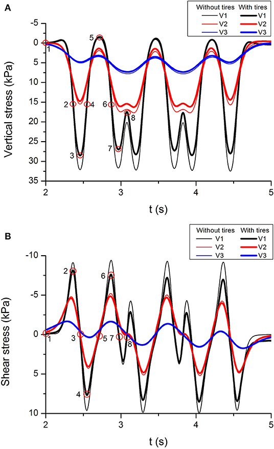
Figure 9. (A) Vertical stress and (B) shear stress at different depth (locations of V1, V2, and V3 are indicated in Figure 4B).
Figure 10 shows the stress paths (i.e., vertical stress Syy against shear stress Syz) followed by the soil element at V1 during the passage of the first bogie (i.e., 1-2-3-4-5) and second bogie (i.e., 5-6-7-8) of the first carriage. In stage 1–2, the vertical stress and shear stress increase as the first bogie approaches, while in stage 2–3, the shear stress decreases while the vertical stress continues to increase until it peaks when the first bogie arrives at position 3. After, the vertical stress begins to decrease, while the shear stress reaches the opposite peak at position 4. Finally, the vertical stress and shear stress both decrease as the first bogie arrives at position 5. As the second bogie approaches, the soil element experiences a different stress path because of the stress superposition caused by two bogies between adjacent carriages. For example, when the second bogie arrives at position 8, the second loading cycle for the soil element is complete, but the vertical stress at position 8 is much higher than at position 5 at the end of first loading cycle. At a lower depth (V2) beneath the track, one bogie corresponds to one loading cycle, but as the depth of soil increases the vertical stress at the end of stage 7–8 moves toward its maximum value, and this may result in two bogies corresponding to one loading cycle. Not surprisingly, the soil near the track experiences more and larger stress cycles than soil at greater depths. This increase in the number of cycles and magnitudes of train loads is likely to result in larger permanent deformation, so the soil at shallower depths is more likely to experience increased displacement and possible shear failure than soil in deeper ground. The use of rubber tires can effectively reduce the magnitude of stress.
FIGURE 10
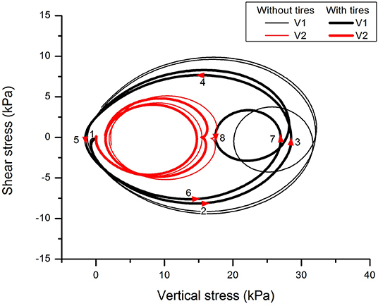
Figure 10. Stress paths for soil element at V1 and V2.
Track Deflection at Critical Speed
Figure 11A shows the predicted track deflection vs. train speed for tracks with and without tires. It can be observed that deflection generally increases as the train speed increases and reaches a maximum deflection at the critical speed, and then decreases as the train speed increases further. Moreover, deflection at high speed with tires is less than without tires. However, the results in Figure 11A indicate that the critical speed for track is not sensitive to the inclusion of tires in the capping layer. For the purpose of illustrating the impact of train speed on the track, the contour plots of vertical deflection along the track with tire reinforcement are shown in Figures 11B–D at three different speeds (i.e., 36, 144, and 360 km/h). Figure 11B shows that at a train speed of 36 km/h, which is considerably lower than the critical speed, vertical deflection is mainly induced near the axles and as expected, there is a slight propagation of wave to the surrounding ground. However, Figure 11C shows that at a critical speed of 144 km/h, vertical deflection is induced near the axles and in the surrounding ground. It is noteworthy that the series of wave fronts radiating from the loading positions appear as a shockwave in the ground that is known as the Mach cone (Krylov, 2011). Figure 11D shows that the vertical deflection of the ground at a train speed 360 km/h which is greater than the critical speed. For this case, the loading speed is greater than the wave speeds and the source passes through wave fronts.
FIGURE 11
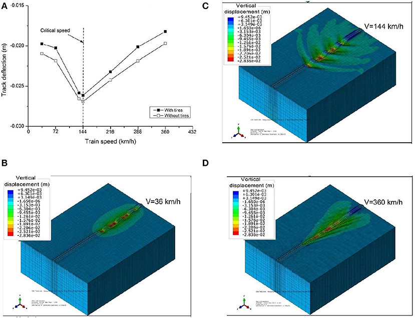
Figure 11. (A) Predicted track deflection vs. train speed with and without rubber tires; (B) typical contour plots of vertical track deflection for train speed of 36 km/h; (C) critical speed 144 km/h; and (D) 360 km/h.
Conclusions
A 3D track/ground FE model was developed to investigate the dynamic response of ballasted railway track with a rubber tire-reinforced capping layer. The moving load was considered by specifying the nodal forces corresponding to the moving load as a function of time. The 3D model was verified and good agreement was found when compared to the field measurements taken at the soft soil site in Ledsgard, Sweden. Various train speeds (i.e., 36–360 km/h) have been simulated to identify the critical train speed for an idealized ground condition. It was found that the critical train speed for the ground condition in this study was 144 km/h. The impacts of break and acceleration of the trains on the railway track degradation and deformation have attracted research interests recently. Two typical subgrades (i.e., fat clay of the Monroe dam representing soft soil and low density sand representing stiff soil) have been considered to investigate the effect of tire-reinforcement on the dynamic response of track-ground system. One of the purposes of this research was to inspire engineer when they design railway tracks. The author acknowledges further detailed research needs to be done on the above mentioned points in the future.
Numerical predictions indicate that track with tire reinforcement experienced less deflection than tracks without tires; this is mainly due to the additional confinement provided to the infill materials that reduces lateral spreading, both of which help to reduce the vertical and lateral displacement of ballast. However, it is acknowledged that further experimental and field test results are needed to validate the conclusion obtained from the numerical simulation. For modeling, an increase in apparent cohesion could be considered to simulate the tire-fill composite. Moreover, the increasing damping property in the capping layer influences the lateral displacement of ballast, an effect that is dominated by the stiffness-proportional Rayleigh damping. As expected, the soil close to the track experiences more and larger stress cycles than soil at greater depths. This increase in the number of cycles and magnitude of train loads will lead to larger permanent deformation, so the soil at shallower depths is more likely to experience increased displacement and possible shear failure than the soil located in deeper ground. The additional confinement provided by tires could reduce the vertical and shear stress, but the improvement is marginal for greater depths. Tire reinforcement is very useful when the substructure overlies a soft foundation; for example, rubber tires in the capping layer reduced lateral spreading by 47.3%. Moreover, track deflection at critical speed with tires is less than without tires, but the critical speed for track is relatively insensitive to the presence of tire reinforcement.
Data Availability Statement
All datasets generated for this study are included in the article/supplementary material.
Author Contributions
BI had provided very critical and constructive review comments at different stages of this work, and was the project leader of this sponsored industry-based research. JG had participated in discussions and provided inspirational comments at various stages of this work, and his company EcoFlex has already put to practice the rubber-tyer assembly concept in numerous Australian road projects. QS approved the article for publication.
Conflict of Interest
QS was employed by the company Coffey Services Australia Pty Ltd. JG was employed by the company Ecoflex International Pty Ltd.
The remaining author declares that the research was conducted in the absence of any commercial or financial relationships that could be construed as a potential conflict of interest.
Acknowledgments
The first author formerly worked as an Associate Research Fellow at University of Wollongong. The authors acknowledge the financial assistance provided by the NSW Environmental Trust, TSA, Ecoflex International Pty Ltd and University of Wollongong. The original concept of tyer assembly for roads was an invention by EcoFlex. The authors are thankful to Dr. Trung Ngo and Dr. Ana Heitor for their valuable review comments to this paper. Assistance of A/Prof. Cholachat Rujikiatkamjorn at various times during this project is also appreciated. Contributions from Dr. Mahdi Biabani through similar conceptual research based on geocell reinforced tracks under the guidance of Distinguished Professor Indraratna supported by EcoFlex also inspired this particular study.
References
Al-Shayea, N., Abduljauwad, S., Bashir, R., Al-Ghamedy, H., and Asi, I. (2003). Determination of parameters for a hyperbolic model of soils. Proc. Inst. Civil Eng. Geotech. Eng. 149, 105–117. doi: 10.1680/geng.2003.156.2.105
ARTC (2011). Locomotive and Rolling Stock Data. Version 2.0., Section 10, 1–33. Australian Rail Track Corporation Ltd.
Bathurst, R. J., and Karpurapu, R. (1993). Large-Scale triaxial compression testing of geocell reinforced granular soils. Geotech. Test. J. 16, 296–303. doi: 10.1520/GTJ10050J
Bian, X., Jiang, H., Cheng, C., Chen, Y., Chen, R., and Jiang, J. (2014). Full-scale model testing on a ballastless high-speed railway under simulated train moving loads. Soil Dyn. Earthq. Eng. 66, 368–384. doi: 10.1016/j.soildyn.2014.08.003
Chang, C. S., Adegoke, C. W., and Selig, E. T. (1980). GEOTRACK model for railroad truck performance. J. Geotech. Eng. Div. 106, 1201–1218.
Connolly, D., Giannopoulos, A., and Forde, M. C. (2013). Numerical modelling of ground borne vibrations from high speed rail lines on embankments. Soil Dyn. Earthq. Eng. 46, 13–19. doi: 10.1016/j.soildyn.2012.12.003
Costa, P. A., Calçada, R., and Cardoso, A. S. (2012). Track–ground vibrations induced by railway traffic: in-situ measurements and validation of a 2.5D FEM/BEM model. Soil Dyn. Earthq. Eng. 32, 111–128. doi: 10.1016/j.soildyn.2011.09.002
Costa, P. A., Calçada, R., Cardoso, A. S., and Bodare, A. (2010). Influence of soil non-linearity on the dynamic response of high-speed railway tracks. Soil Dyn. Earthq. Eng. 30, 221–235. doi: 10.1016/j.soildyn.2009.11.002
Duncan, J. M., Byrne, P., Wong, K. S., and Mabry, P. (1980). Strength, Stress–Strain and Bulk Modulus Parameters for Finite Element Analyses of Stresses and Movements in Soil Masses. Geotechnical Engineering Report No. UCB/GT/80-01, University of California, CA.
El Kacimi, A., Woodward, P. K., Laghrouche, O., and Medero, G. (2013). Time domain 3D finite element modelling of train-induced vibration at high speed. Comput. Struct. 118, 66–73. doi: 10.1016/j.compstruc.2012.07.011
Feng, B., Hou, W., and Tutumluer, E. (2019). Implications of field loading patterns on different tie support conditions using discrete element modeling: dynamic responses. Transport. Res. Rec. 2673, 509–520. doi: 10.1177/0361198118821936
Hall, L. (2003). Simulations and analyses of train-induced ground vibrations in finite element models. Soil Dyn. Earthq. Eng. 23, 403–413. doi: 10.1016/S0267-7261(02)00209-9
Heath, D. L., Shenton, M. J., Sparrow, R. W., and Waters, J. M. (1972). Design of conventional rail track foundations. Proc. Inst. Civil Eng. 51, 251–267. doi: 10.1680/iicep.1972.5952
Hibbitt Karlsson & Sorensen, Inc. (2014). ABAQUS User's Manual, Version 6.14. Hibbitt, Karlsson & Sorensen, Inc.
Huang, Y. H., Lin, C., Deng, X., and Rose, J. (1986). KENTRACK, Finite Element Computer Program for the Analysis of Railroad Tracks. Lexington, KY: Department of Civil Engineering, University of Kentucky.
Indraratna, B., Biabani, M. M., and Nimbalkar, S. (2015). Behavior of geocell-reinforced subballast subjected to cyclic loading in plane-strain condition. J. Geotech. Geoenviron. Eng. ASCE 141:04014081. doi: 10.1061/(ASCE)GT.1943-5606.0001199
Indraratna, B., Sun, Q., and Grant, J. (2017). Behaviour of subballast reinforced with used tyre and potential application in rail tracks. Transport. Geotech. 12, 26–36. doi: 10.1016/j.trgeo.2017.08.006
Indraratna, B., Sun, Q., Heitor, A., and Grant, J. (2018). Performance of rubber tyre-confined capping layer under cyclic loading for railroad conditions. J. Mater. Civil Eng. 30:06017021. doi: 10.1061/(ASCE)MT.1943-5533.0002199
Ju, S. H., Liao, J. R., and Ye, Y. L. (2010). Behavior of ground vibrations induced by trains moving on embankments with rail roughness. Soil Dyn. Earthq. Eng. 30, 1237–1249. doi: 10.1016/j.soildyn.2010.05.006
Kargarnovin, M. H., and Younesian, D. (2004). Dynamics of Timoshenko beams on Pasternak foundation under moving load. Mech. Res. Commun. 31, 713–723. doi: 10.1016/j.mechrescom.2004.05.002
Kargarnovin, M. H., Younesian, D., Thompson, D. J., and Jones, C. J. C. (2005). Response of beams on nonlinear viscoelastic foundations to harmonic moving loads. Comput. Struct. 83, 1865–1877. doi: 10.1016/j.compstruc.2005.03.003
Karlstrom, A., and Bostrom, A. (2006). An analytical model for train-induced ground vibrations from railways. J. Sound Vib. 292, 221–241. doi: 10.1016/j.jsv.2005.07.041
Kaynia, A. M., Madshus, C., and Zackrisson, P. (2000). Ground vibration from high-speed trains: prediction and countermeasure. J. Geotech. Geoenviron. Eng. ASCE 126, 531–537. doi: 10.1061/(ASCE)1090-0241(2000)126:6(531)
Kenney, J. T. (1954). Steady-state vibrations of beam on elastic foundation for moving load. J. Appl. Mech. 21, 359–364.
Kouroussis, G., Connolly, D. P., and Verlinden, O. (2014). Railway-induced ground vibrations-a review of vehicle effects. Int. J. Rail Transport. 2, 69–110. doi: 10.1080/23248378.2014.897791
Kouroussis, G., Verlinden, O., and Conti, C. (2009). Ground propagation of vibrations from railway vehicles using a finite/infinite-element model of the soil. Proc. Inst. Mech. Eng. F J. Rail Rapid Transit 223, 405–413. doi: 10.1243/09544097JRRT253
Krylov, V. V. (1995). Generation of ground vibrations by superfast trains. Appl. Acoust. 44, 149–164. doi: 10.1016/0003-682X(95)91370-I
Leshchinsky, B., and Ling, H. (2012). Effects of geocell confinement on strength and deformation behavior of gravel. J. Geotech. Geoenviron. Eng. ASCE 139, 340–352. doi: 10.1061/(ASCE)GT.1943-5606.0000757
Leshchinsky, B., and Ling, H. (2013). Numerical modelling of behavior of railway ballasted structure with geocell confinement. Geotext. Geomembr. 36, 33–43. doi: 10.1016/j.geotexmem.2012.10.006
Lombaert, G., and Degrande, G. (2009). Ground-borne vibration due to static and dynamic axle loads of Inter City and high-speed trains. J. Sound Vib. 319, 1036–1066. doi: 10.1016/j.jsv.2008.07.003
Madshus, C., and Kaynia, AM. (2000). High-speed railway lines on soft ground: dynamic behaviour at critical train speed. J. Sound Vib. 231, 689–701. doi: 10.1006/jsvi.1999.2647
Okabe, Z. (1961). Laboratory Investigations of Railroad Ballast. Permanent Way, No. 11. Osaka City University.
Picoux, B., and Le Houedec, D. (2005). Diagnosis and prediction of vibration from railway trains. Soil Dyn. Earthq. Eng. 25, 905–921. doi: 10.1016/j.soildyn.2005.07.002
Robnett, Q. L., Thompson, M. R., Knutson, R. M., and Tayabji, S. D. (1975). Development of a Structural Model and Materials Evaluation Procedures. Report No. dot-fr-30038, University of Illinois, Champaign, Champaign, IL.
Sayeed, M. A., and Shahin, M. A. (2016). Three-dimensional numerical modelling of ballasted railway track foundations for high-speed trains with special reference to critical speed. Transport. Geotech. 6, 55–65. doi: 10.1016/j.trgeo.2016.01.003
Sheng, X., Jones, C. J. C., and Petyt, M. (1999). Ground vibration generated by harmonic load acting on a railway track. J. Sound Vib. 225, 3–28. doi: 10.1006/jsvi.1999.2232
Sheng, X., Jones, C. J. C., and Thompson, D. J. (2003). A comparison of a theoretical model for quasi-statically and dynamically induced environmental vibration from trains with measurements. J. Sound Vib. 267, 621–635. doi: 10.1016/S0022-460X(03)00728-4
Sheng, X., Jones, C. J. C., and Thompson, D. J. (2005). Modelling ground vibration from railways using wavenumber finite- and boundary-element methods. Proc. R. Soc. A Math. Phys. Eng. Sci. 461, 2043–2070. doi: 10.1098/rspa.2005.1450
Shih, J.-Y., Thompson, D. J., and Zervos, A. (2016). The effect of boundary conditions, model size and damping models in the finite element modeling of moving load on a track/ground system. Soil Dyn. Earthq. Eng. 89, 12–27. doi: 10.1016/j.soildyn.2016.07.004
Shih, J.-Y., Thompson, D. J., and Zervos, A. (2017). The influence of soil nonlinear properties on the track/ground vibration induced by trains running on soft ground. Transport. Geotech. 11, 1–16. doi: 10.1016/j.trgeo.2017.03.001
Sitharam, T. G., and Hegde, A. (2013). Design and construction of geocell foundation to support the embankment on settled red mud. Geotext. Geomembr. 41, 55–63. doi: 10.1016/j.geotexmem.2013.08.005
Takemiya, H., and Bian, X. (2005). Substructure simulation of inhomogeneoust track and layered ground dynamic interaction under train passage. J. Eng. Mech. ASCE 131, 699–711. doi: 10.1061/(ASCE)0733-9399(2005)131:7(699)
Yang, Y. B., Hung, H. H., and Chang, D. W. (2003). Train-induced wave propagation in layered soils using finite/infinite element simulation. Soil Dyn. Earthq. Eng. 23, 263–278. doi: 10.1016/S0267-7261(03)00003-4
Yang, Y. B., and Yau, J. D. (1997). Vehicle-bridge interaction element for dynamic anlysis. J. Struct. Eng. 123, 1512–1518. doi: 10.1061/(ASCE)0733-9445(1997)123:11(1512)
Zhang, L., Zhao, M., Shi, C., and Zhao, H. (2010). Bearing capacity of geocell reinforcement in embankment engineering. Geotext. Geomembr. 28, 475–482. doi: 10.1016/j.geotexmem.2009.12.011
List of Symbols
Δt is time step between two loading nodes
Δx is loading nodes space
Δσ3′ is additional confining stress
A is area of the beam section
Cc is apparent cohesion of capping layer
C is damping matrix
D is the initial diameter of the tire
E is Young's modulus of materials
Ec is Young's modulus of capping layer
I is second moment of area
K is stiffness matrix
kv is suspension stiffness
L is length of the beam
Mt is the tensile stiffness of the tire
M is mass matrix
Mv is mass of vehicle
Syy is vertical stress
Syz is shear stress
V is vehicle speed
α is Rayleigh damping mass proportional parameter
β is Rayleigh damping stiffness proportional parameter
εa is the axle strain of the sample
η is loss factor
N is Poisson's ratio
ξ is damping ratio
ξc is damping ratio of capping layer
ρ is mass density of the beam
ϕ is friction angle
ω is circular frequency
Keywords: track dynamics, finite-element modeling, vibration, reinforced soils, capping layer, scrap tire
Citation: Sun Q, Indraratna B and Grant J (2020) Numerical Simulation of the Dynamic Response of Ballasted Track Overlying a Tire-Reinforced Capping Layer. Front. Built Environ. 6:6. doi: 10.3389/fbuil.2020.00006
Received: 23 August 2019; Accepted: 14 January 2020;
Published: 05 February 2020.
Edited by:
Sanjay Shrawan Nimbalkar, University of Technology Sydney, AustraliaCopyright © 2020 Sun, Indraratna and Grant. This is an open-access article distributed under the terms of the Creative Commons Attribution License (CC BY). The use, distribution or reproduction in other forums is permitted, provided the original author(s) and the copyright owner(s) are credited and that the original publication in this journal is cited, in accordance with accepted academic practice. No use, distribution or reproduction is permitted which does not comply with these terms.
*Correspondence: Qideng Sun, Peter.Sun@Coffey.com
†Formerly worked as an Associate Research Fellow at University of Wollongong, Australia
‡Formerly worked at ARC Industrial Transformation Training Centre, ITTC-Rail, c/o University of Wollongong, Wollongong, NSW, Australia