- 1Department of Architecture and Architectural Engineering, Graduate School of Engineering, Kyoto University, Kyoto, Japan
- 2Department of Architecture and Urban Design, Ritsumeikan University, Kusatsu, Japan
In most building structures, floors with sufficient in-plane stiffness exist and an assumption of rigid in-plane stiffness is valid. However, in some building structures, an assumption of rigid in-plane stiffness does not hold. A method of system identification (SI) for physical parameters (stiffness, damping) is proposed for three-dimensional (3D) building structures with in-plane flexible floors. The stiffness and damping parameters of each vertical structural frame in the 3D building structure are identified from the measured floor horizontal accelerations together with the stiffness and damping parameters of each floor. It is shown that a batch processing least-squares estimation method for many discrete time-domain measured data enables the direct identification of both the stiffness and damping parameters of each vertical structural frame and the stiffness and damping parameters of each floor. The proposed method possesses an advantage that all stiffness and damping parameters of vertical frames and horizontal frames (floors) can be identified simultaneously without search iteration. The accuracy and reliability of the proposed method are made clear by numerical simulations for measured data without noise and measured data with noise. A method of noise elimination is proposed to enhance the identification accuracy. Finally, experiments using a shaking table are conducted for the accuracy investigation of the proposed identification method. It is confirmed that the proposed identification method possesses a reliable ability to identify the stiffness and damping parameters for 3D building structures with in-plane flexible floors.
Introduction
A new method of physical-parameter system identification is proposed in this paper for three-dimensional (3D) building structures with in-plane flexible floors. The 3D building structure consists of multiple vertical frames and multiple horizontal frames representing floors. The stiffness and damping parameters of vertical frames and horizontal frames are identified from the measured floor horizontal accelerations. The plane frame-wise identification (vertical and horizontal) of stiffness and damping is the most outstanding point in its novelty.
There exists a very limited number of researches on physical-parameter system identification of 3D building structures with eccentricity (for example Omrani et al., 2012; Nabeshima and Takewaki, 2017; Shintani et al., 2017; Fujita and Takewaki, 2018). The existence of many parameters to be identified in 3D building structures may be one reason for difficulty. Omrani et al. (2012) developed a method based on the statistical analysis for known stiffness eccentricity. Since the eccentricity cannot be defined in this paper, a completely different formulation will be proposed.
Structural health monitoring (SHM) was started many years ago in aerospace, mechanical and civil engineering (Doebling et al., 1996; Boller et al., 2009; Takewaki et al., 2011). The system identification (SI) methodologies are at the center of SHM. The physical-parameter (PP) SI and modal-parameter (MP) SI are two principal approaches in the field of SI. Much attention has been paid historically to the MP SI (Hart and Yao, 1977; Agbabian et al., 1991; Nagarajaiah and Basu, 2009) because it can provide the overall mechanical properties of a structural system and has a stable characteristic. The determination of modal damping is an important issue (Sivandi-Pour et al., 2014, 2015, 2016). On the contrary, the PP SI has another merit from a different point of view. The direct identification of physical parameters is quite effective for the damage detection. In spite of the fact that the PP SI is preferred in SHM, its advancement is slow because of the strict condition of multiple measurements or the requirement of complicated procedures (Hart and Yao, 1977; Udwadia et al., 1978; Shinozuka and Ghanem, 1995; Takewaki and Nakamura, 2000, 2005; Brownjohn, 2003; Nagarajaiah and Basu, 2009; Takewaki et al., 2011; Zhang and Johnson, 2013a,b; Johnson and Wojtkiewicz, 2014; Wojtkiewicz and Johnson, 2014).
In PP SI, Nakamura and Yasui (1999) introduced a direct method with the least-squares concept. Since their approach needs too many points of measurement, it can be applied only for simple 1D shear-type building models. On the other hand, Takewaki and Nakamura (2000, 2005) developed a unique SI concept which is originally from the work by Udwadia et al. (1978) for a shear building model (S model). Although the SI method by Takewaki and Nakamura (2000, 2005) was innovative, an additional effort should be provided in applying to actual data represented by micro-tremors (Ikeda et al., 2014; Fujita et al., 2015; Koyama et al., 2015). This may result from the small signal/noise (SN) ratio especially in the low frequency range. In addition, a S model is not necessarily an appropriate model of high-rise buildings with large height-width (aspect) ratios. To respond to the former noise problem, the ARX (Auto-Regressive with eXogenous) model with constraints on the ARX parameters was introduced by Maeda et al. (2011), Kuwabara et al. (2013), Minami et al. (2013) and Ikeda et al. (2015). On the other hand, the latter problem has been tackled by extending the SI algorithm to the shear-bending model (SB model) (Fujita et al., 2013; Minami et al., 2013).
To develop a hybrid method of the MP and PP SIs, some researchers proposed a reliable SI method. The physical parameters are recovered from the pre-identified modal parameters (Hjelmstad et al., 1995; Song et al., 2018) in this hybrid method, in which, the relation between the physical and modal parameters has to be made clear together with the need of detailed theoretical investigations on inverse problem formulation (Hjelmstad, 1996).
The SI method using Kalman filter or extended Kalman filter was developed many years ago as another effective approach (Hoshiya and Saito, 1984). While its approach is general and can consider noise issues, a complicated mathematical treatment has to be conducted and a simple use seems difficult. In recent years, a Bayesian updating approach to the SI is developing very fast (Boller et al., 2009).
Recently a new method of PP SI was developed in the frequency domain by Nabeshima and Takewaki (2017) for 3D building structures with stiffness eccentricity and rigid in-plane stiffness of floors. Shintani et al. (2017) developed another method of PP SI for 3D building structures with stiffness eccentricity and rigid in-plane stiffness of floors. Although the paper by Shintani et al. (2017) for rigid floor models is a preliminary version of the present paper, the extension is not simple.
In most building structures, floors with sufficient in-plane stiffness exist and an assumption of rigid in-plane stiffness is acceptable. However, in some building structures, e.g., with stairs opening or without in-plane stiffness component (brace), an assumption of rigid in-plane stiffness does not hold. A method of PP SI is proposed for 3D building structures with in-plane flexible floors. The stiffness and damping parameters of each vertical structural frame in the 3D building structure are identified from the measured floor horizontal accelerations together with the stiffness and damping parameters of each floor. It is shown that a batch processing least-squares estimation method for many discrete time-domain measured data enables the direct identification of both the stiffness and damping parameters of each vertical structural frame and the stiffness and damping parameters of each floor. An advantageous feature of the proposed SI method is that the identification of all stiffness and damping parameters of each vertical structural frame and each floor can be performed simultaneously without search iteration. The accuracy and reliability of the proposed method are demonstrated by numerical simulations for measured data without noise and measured data with noise. A method of noise elimination is proposed to enhance the identification accuracy. Finally, experiments using a shaking table are conducted for the accuracy investigation of the proposed SI method. It is confirmed that the proposed SI method possesses a reliable ability to identify the stiffness and damping parameters for 3D building structures with in-plane flexible floors.
Modeling of Building With In-plane Flexible Floors
It is assumed that the in-plane stiffness of floors is finite. The relative stiffness of a floor element which connects two consecutive vertical frames at the same floor level is expressed by a shear spring and the relative damping of the floor element between two consecutive vertical frames is represented by a dashpot.
We consider an N-story 3D shear building model, as shown in Figure 1A, with in-plane flexible horizontal floors (Figures 1B,C). This model is subjected to the horizontal ground acceleration g which has an inclination angle ϕ with respect to the x direction. Each story of this model has n vertical plane frames parallel to the x axis and m vertical plane frames parallel to the y axis. Let xj(j = 1, …, m) and yl(l = 1, …, n) denote the j-th vertical frame parallel to the y axis and the l-th vertical frame parallel to the x axis, respectively. Let , and denote the horizontal stiffness and damping coefficients of the yl and xj vertical plane frames in the i-th story. If xj(j = 1, …, m − 1) and yl(l = 1, …, n − 1) are used for span (between two consecutive vertical frames), these indicate the quantities related to span. and denote the span length in the x direction and that in the y direction, respectively. Let and denote the in-plane shear stiffness and damping coefficient of floor per unit length in the [xj, yl] span of the i-th story. denotes the floor masses located at the point of intersection of x and y direction frames.

Figure 1. 3D shear building model composed of vertical plane frames and connected by in-plane flexible floors subjected to inclined horizontal ground motion. (A) Overview, (B) Plan, (C) In-plane floor deformation.
Modeling of Structural Behavior
Degrees of Freedom
The total number of degrees of freedom in the present model is (m + n)N. Let and denote the horizontal displacements of the i-th story in the l-th vertical frame parallel to the x axis and in the j-th vertical frame parallel to the y axis, respectively. When u[yl] and v[xj] are defined as displacement vectors which contain N elements and (i = 1, …, N), respectively, the total displacement vector y can be expressed by.
Equations of Motion
When the mass, damping and stiffness matrices are expressed by M, C, K and total velocity and acceleration vectors are expressed by ẏ, , (m + n)N equations of motion can be arranged as follows (see Appendix 1):
where
In Equation (6), Mx and My are diagonal matrices which consist of the sum of masses in the same frame in x and y directions, respectively. In Equation (7), KW indicates the stiffness matrix of vertical wall elements. KW consists of block matrices (l = 1, ⋯ , n) and (j = 1, ⋯ , m) along diagonal. and are the N × N tri-diagonal matrices which are expressed as the sum of the following 2 × 2submatrices in the i-th and (i+1)-th rows and columns, respectively.
In Equation (7), KF indicates the stiffness matrix of horizontal floor elements. KF is expressed as the sum of the following 4 × 4 submatrices of floor element at j-th x-span and l-th y-span in the rows and columns corresponding to the degrees of freedom :
The damping matrix C can be defined in the same way as the stiffness matrix K by replacing the character k and K for stiffness with c and C for damping coefficients in Equations (7)-(9), (11).
Formulation of Identification of Stiffness and Damping Coefficient in Vertical Frame and Horizontal Frame (Floor)
A new formulation of system identification of frames with in-plane flexible floors is presented here.
Assume that g(t) and {(t)+rg(t)} are measured simultaneously. For example, it may be sufficient to measure the x and y-direction absolute accelerations at all floors in all vertical frames in Figure 1A in addition to the x and y-direction absolute accelerations at the base. The velocities and displacements y(t) can then be integrated from (t) numerically.
The unknown parameter vector Θ is defined by
kx and ky represent the vectors of the vertical frame stiffness which consist of n × N stiffness in x direction and m × N stiffness in y-direction, respectively. Gk represents a vector of (n − 1)(m − 1)N in-plane floor stiffness . cx, cy, and Gc represent the vectors of damping coefficients of the vertical frame in x-direction and y-direction and in-plane floor.
The third term of the left hand side of the equation of motion, Equation (4), can be transformed into the sum of products of known matrices HW(t), HF(t), and unknown parameters kx, ky, Gk. HW(t) and HF(t) can then be estimated from the measured displacement y(t).
A similar form can be obtained for the second term of Equation (4) by replacing the character k with c for damping coefficient and replacing H with Ḣ for velocity. Finally, the equation of motion, Equation (4), can be transformed into the following relations (see Appendix 2).
where
Equation (15) is the equation that should be satisfied at every time. However, the number of unknown parameters is larger than the number of equations in Equation (15). For this reason, the least-squares estimation method incorporating the batch processing (Takewaki and Nakamura, 2010) is used here. The errors in Equation (15) can be expressed by
The sum of squared errors e(t) from t1 to t2 can be expressed by
The differential of E in Equation (19) for Θ provides
The method of least-squares estimation with the batch processing (Takewaki and Nakamura, 2010) provides the parameters Θ for which the error E is minimized.
Equation (21) indicates that all stiffness and damping parameters can be identified without iteration.
Numerical Example
Example of Model With Only Outer Frame
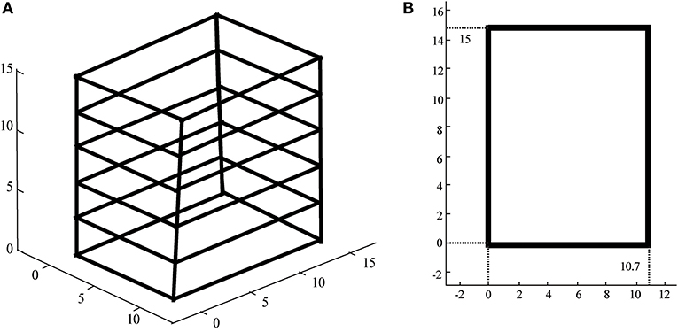
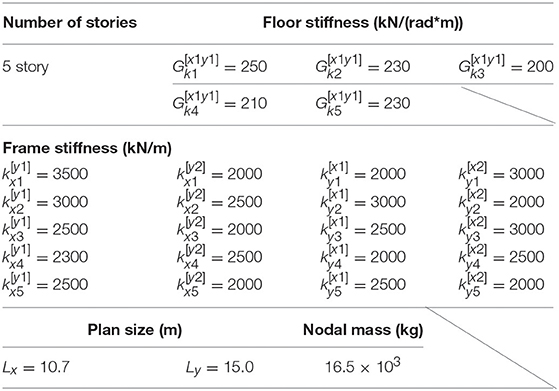
In order to verify the validity and accuracy of the proposed method, a 5-story model as shown in Figure 2 is used. The model parameters are shown in Table 1. In this example, proportional damping is assumed and the damping matrix C is estimated as C = (2h(1)/ω(1))K where h(1) is the lowest-mode damping ratio and ω(1) is the undamped fundamental natural circular frequency of the model. h(1)is assumed to be 0.02. As an input ground motion, the first ten second of Hachinohe NS, 1968 is used and input in the direction angle ϕ = π/4. The time-history response of this model is simulated numerically using the Newmark-beta method. The time increment for numerical integration is 0.02 s.
Figure 3A shows the correspondence between the given stiffness parameters, (i) vertical frame, (ii) horizontal frame (floor in-plane stiffness), and the identified values in the 5-story model. On the other hand, Figure 3B presents the correspondence between the given damping coefficient parameters, (i) vertical frame, (ii) horizontal frame (floor in-plane damping), and the identified values in the 5-story model. A fairly good correspondence can be observed.
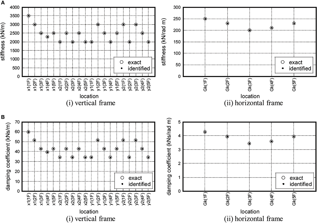
Figure 3. Stiffness and damping coefficient parameters of 5-story model. (A) Stiffness parameter, (B) Damping parameter.
Example of Model With Inner and Outer Frames
Examples Without Noise
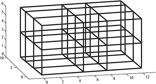
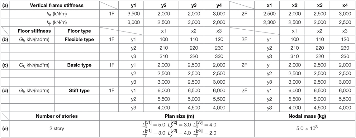
Consider another 2-story frame model with three spans in both horizontal directions, as shown in Figure 4. The model parameters are shown in Table 2. Three levels of in-plane stiffness parameters of floors are considered [Tables 2(b–d)]. Table 2(c) is the basic case, Table 2(b) is the case of rather flexible floors and Table 2(d) is the case of rather stiff floors. The results of the basic case will be presented in this paper. It should be noted that the difference of the stiffness of floors does not influence the accuracy so much in the identification of vertical frames and horizontal frames (floors).
Figure 5A show the correspondence between the given stiffness parameters, (i) vertical frame, (ii) horizontal frame (floor in-plane stiffness), and the identified values in the 2-story model. On the other hand, Figure 5B present the correspondence between the given damping coefficient parameters, (i) vertical frame, (ii) horizontal frame (floor in-plane damping), and the identified values in the 2-story model.
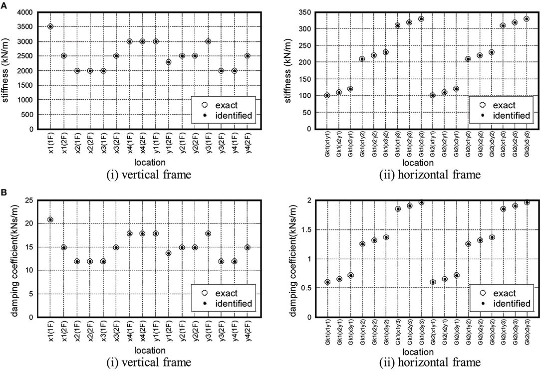
Figure 5. Stiffness and damping coefficient parameters of 2-story model. (A) Stiffness parameter, (B) Damping parameter.
Examples With Noise
In order to investigate the influence of noise on the accuracy of identification, the input and response values are colored by noise. A band-limited white noise produced in the frequency range 0.075–150 (rad/s) is used as a noise. To guarantee the probabilistic independence, different independent noises are added to the original input and response data (acceleration, velocity and displacement). RMS (root-mean-squares) values are employed to evaluate and quantify the noise level and the first 10 s data from the beginning are used for identification.
Figure 6 shows the influence of story stiffness and damping coefficient on the noise level in the 2-story model. It can be observed from Figure 6 that, while the accuracy of stiffness decreases gradually as the noise level increases, the order of accuracy degradation in damping is larger. This fact corresponds well to the well-recognized knowledge in SI (Takewaki and Nakamura, 2005; Boller et al., 2009; Takewaki et al., 2011). Furthermore, while most stiffness become smaller as the noise level increases, damping coefficients become smaller or larger.
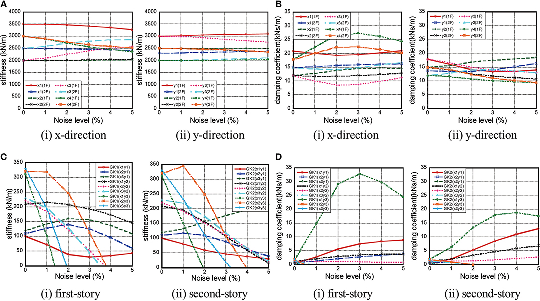
Figure 6. Influence of noise level on accuracy of identification. (A) Vertical frame stiffness, (B) Vertical frame damping coefficient, (C) Floor in-plane stiffness, (D) Floor in-plane damping coefficient.
In addition, it can be confirmed that the influence of noise in the horizontal frames is greater in both the stiffness and the damping coefficient in comparison with the vertical frames. This is because the stiffness and damping coefficients, which are unknowns of the vertical frame in the yl frame of the i story, are influenced by the two equations of motion in the yl frame of the i and (i+1) stories. On the other hand, the shear stiffness and damping coefficient, which are unknowns of the floor in the yl frame of the i story, are influenced by the four equations of motion in the yl, y(l+1), xj, and x(j+1) frame of the i story. The accumulation of identification errors in floors in Equation (15) increases compared to the vertical frames and the identification accuracy in floor stiffness and damping decreases.
Denoising Procedure
To eliminate the noise bias, a method is introduced. Measurement data at floors and base are divided into q intervals. Each interval of measurement data consists of p data. Construct the following p × q matrix A.
where
In Equation (25), the singular-value decomposition is conducted. Let s(r) denote the Frobenius norm ratio. Determine the effective order r of the singular value satisfying the limit condition.
Using the singular values and singular-value vectors, set the following matrix as a new response data after noise processing.
The effectiveness of this noise processing will be investigated next.
As an input wave motion, El Centro NS, 1940 (first 10s) is used here. The parameters p and q defined above are set as p = 200, q = 5. Figure 7 shows the identification accuracy for increasing the noise level before and after denoising. The accuracy on only stiffness is investigated. Figures 7A,B present the identification accuracies for the increasing noise level before and after denoising for x-direction vertical frame stiffness, y-direction vertical frame stiffness, floor in-plane stiffness (first story) and floor in-plane stiffness (second story), respectively. It can be observed that the identification accuracy is enhanced by the proposed noise elimination procedure. However, the enhancement degree is low in the horizontal frame (floor in-plane stiffness). This may result from the small differences of measurement data between the neighboring vertical frames (these indicate the shear deformation of floors) and the difference in error accumulation.
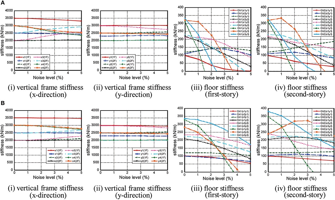
Figure 7. Identification accuracy for increasing noise level before and after denoising. (A) Before denoising, (B) After denoising.
Experimental Verification
Tests Description
In order to demonstrate the validity of the proposed method through physical experiment, a 2-story model, as shown in Figure 8A, has been used. The floors are composed of steel plates and steel blocks. The columns are constructed by steel bars with different size to introduce stiffness eccentricities. On the other hand, the center of mass is at the center of floors. Four accelerometers are set at every floor and two accelerometers are set at the base. The model parameters are shown in Table 3. The damping ratio in the lowest mode is assumed to be 0.002 judging from the preliminary experiment. As an input ground motion, an amplitude adjusted El Centro NS, 1940 (Figure 8B) has been used and input in the direction angle ϕ = π/6. Due to the accuracy of re-production of input wave on the shaking table, a slightly modified ground motion from the original El Centro NS, 1940 was input. As shown in Figure 8A, accelerometers are put in four places on each floor. The measurement data used for identification are acquired during a forced-vibration stage or a free-vibration stage. The time duration is 10 s and the time increment is 0.01 s.

Figure 8. Experimental frame model and input. (A) Two-story frame model used in experiment, (B) Input seismic wave.
Reference Static Test
The reference stiffness is estimated from the static loading (one-way monotonic) test as shown in Figures 9A,B. Due to the limitation of the measurement, the load test is conducted by restraining the horizontal frame with an acrylic plate for lateral stiffness. Figures 9C–E show the static loading (one-way monotonic) test results for the Y1-side frame stiffness, Y2-side frame stiffness and the horizontal frame (floor).
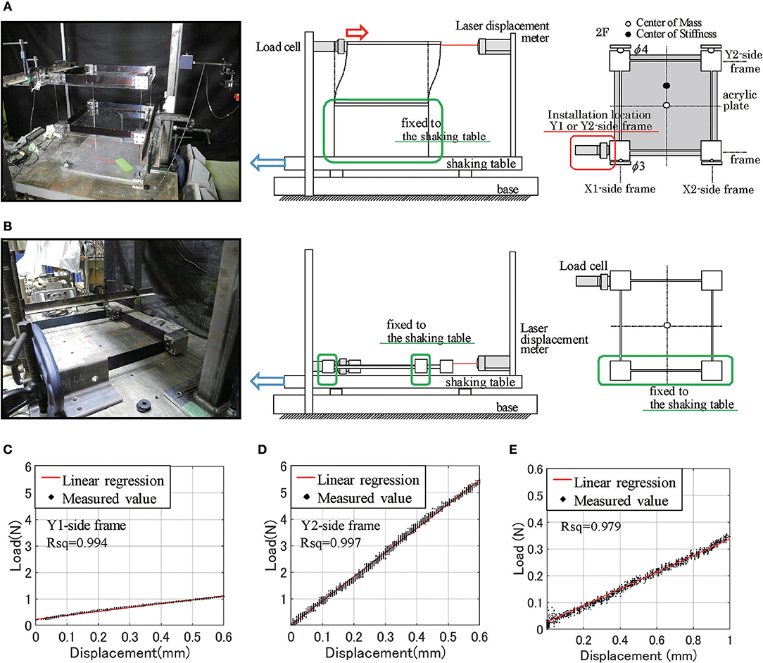
Figure 9. Static loading test and its result. (A) Stiffness for vertical frame, (B) Stiffness for horizontal frame, (C) Y1-side frame stiffness, (D) Y2-side frame stiffness, (E) Horizontal frame stiffness.
As another method, the reference stiffness of the vertical frame is estimated by using the natural frequency ratio between the transfer function derived from the experiment and that from the assumed model.
Shaking Table Test and Identification of Vertical Frame Stiffness and Floor In-plane Stiffness
The left figure in Figure 10A shows the comparison of stiffness of vertical frames among the reference-dynamic, the reference-static (Figure 9), the identified-flexible floor (without denoising) and the identified-flexible floor (denoise: after denoising) (i): forced-vibration data, (ii): free-vibration data. The reference-dynamic was derived from the natural frequency ratio between the transfer function derived from the experiment and that from the assumed model. The parameters p and q defined above for denoising are set as p = 200, q = 5. The identified values are the means of 500 identifications. These 500 identifications have been obtained by shifting the data windows of 5 s sequentially by 0.01 s. The right one in Figure 10A indicates the statistical plots (median, maximum, minimum, 25% exceedance, and 75% exceedance, outlier) of these 500 identified values without denoising. This figure was drawn via Matlab (boxplot) and the maximum and minimum values are evaluated by disregarding the outliers (red marks). On the other hand, Figure 10B shows the comparison of the stiffness of horizontal frames (floors) without denoising (i): forced-vibration data, (ii): free-vibration data.
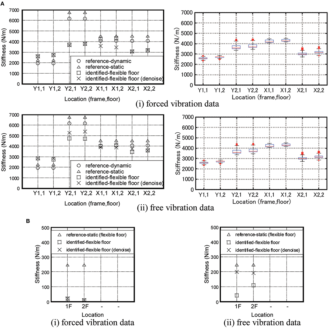
Figure 10. Identification of stiffness. (A) Stiffness of vertical frame, (B) Floor in-plane stiffness.
It can be observed that the proposed identification method has a reliable accuracy after the application of noise elimination procedure. It can also be found that the free-vibration data lead to more reliable and accurate results compared to the forced-vibration results and the identification of vertical frames is more accurate than floors (horizontal frames) as seen in the numerical examples.
Conclusions
A method of PP SI (physical-parameter system identification) has been proposed for 3D building structures with in-plane flexible floors. In this method, the stiffness and damping parameters of each vertical structural frame and the stiffness and damping coefficients of each floor are identified from the measured floor horizontal accelerations. The following conclusions have been derived.
(1) A method of batch processing least-squares estimation using many discrete measured data has been proposed for the identification of the stiffness and damping parameters of each vertical structural frame and those of each floor. A model with in-plane flexible floors has been used as a new model for PP SI. The proposed method possesses the advantage that all stiffness and damping parameters of each vertical structural frame and those of each floor can be performed simultaneously without search iteration.
(2) Numerical simulations demonstrated that the proposed method is accurate and reliable for noise-free models. On the other hand, the identification accuracy decreases gradually as the noise level increases. As the noise level increases, the accuracy of identification in the stiffness and damping parameters of horizontal frames (floor) is relatively low. This is because the accumulation of identification errors in floors increases compared to the vertical frames. However, a certain accuracy level can be maintained by limiting the level of noise.
(3) To eliminate the noise bias, a method has been introduced. It has been observed that the identification accuracy can be enhanced by the proposed noise elimination procedure. However, the enhancement degree is low in the horizontal frame (floor in-plane stiffness).
(4) Physical experiments have been conducted to investigate the reliability and accuracy of the proposed PP SI. It has been observed that the proposed identification method has a reliable accuracy for stiffness after the application of the noise elimination procedure. It has also been found that the free-vibration data lead to more reliable and accurate results compared to the forced-vibration results. The identification of vertical frames is more accurate than that of floors (horizontal frames) as seen in the numerical examples.
When the inner vertical frames exist in addition to the outer vertical frames, the corresponding accelerometers on the inner vertical frames have to be placed.
Data Availability
The datasets generated for this study are available on request to the corresponding author.
Author Contributions
KS formulated the problem, conducted the computation, conducted the experiment, and wrote the paper. SY formulated the problem, helped the computation, and wrote the paper. KF conducted the experiment and wrote the paper. IT supervised the research, formulated the problem, and wrote the paper.
Funding
Part of the present work was supported by the Grant-in-Aid for Scientific Research (KAKENHI) of Japan Society for the Promotion of Science (Nos. 18H01584 and 18J20177). This support was greatly appreciated.
Conflict of Interest Statement
The authors declare that the research was conducted in the absence of any commercial or financial relationships that could be construed as a potential conflict of interest.
Abbreviations
ARX, auto-regressive with exogenous; MP, modal-parameter; PP, physical-parameter; SB model, shear-bending model; S model, shear model; SN, signal/noise; SI, system identification; 3D, three-dimensional.
References
Agbabian, M. S., Masri, S. F., Miller, R. K., and Caughey, T. K. (1991). System identification approach to detection of structural changes. J. Eng. Mech. ASCE 117, 370–390. doi: 10.1061/(ASCE)0733-9399(1991)117:2(370)
Boller, C., Chang, F.-K., and Fujino, Y. (Eds). (2009). Encyclopedia of Structural Control and Health Monitoring. Vol. 1–5, Chichester, UK: Wiley.
Brownjohn, J. M. W. (2003). Ambient vibration studies for system identification of tall building. Earthq. Eng. Struct. Dyn. 32, 71–95. doi: 10.1002/eqe.215
Doebling, S. W., Farrar, C. R., Prime, M. B., and Shevitz, D. W. (1996). Damage Identification and Health Monitoring of Structural and Mechanical Systems From Changes in Their Vibration Characteristics, A Literature Review. Los Alamos National Laboratory Report, LA-13070-MS.
Fujita, K., Ikeda, A., Shirono, M., and Takewaki, I. (2013). System identification of high-rise buildings using shear-bending model and ARX model: experimental inves-tigation. Proceedings of ICEAS13 in ASEM13, September 8–12 (Jeju), 2803–2815.
Fujita, K., Ikeda, A., and Takewaki, I. (2015). Application of story-wise shear building identification method to actual ambient vibration. Front. Built Environ. 1:2. doi: 10.3389/fbuil.2015.00002
Fujita, K., and Takewaki, I. (2018). Stiffness identification of high-rise buildings based on statistical model-updating approach. Front. Built Environ. 4:9. doi: 10.3389/fbuil.2018.00009
Hart, G. C., and Yao, J. T. P. (1977). System identification in structural dynamics. J. Eng. Mech. Div. ASCE 103, 1089–1104.
Hjelmstad, K. D. (1996). On the uniqueness of modal parameter estimation. J. Sound Vib. 192, 581–598. doi: 10.1006/jsvi.1996.0205
Hjelmstad, K. D., Banan, Mo. R., and Banan, Ma. R. (1995). On building finite element models of structures from modal response. Earthq. Eng. Struct. Dyn. 24, 53–67. doi: 10.1002/eqe.4290240105
Hoshiya, M., and Saito, E. (1984). Structural identification by extended Kalman filter. J. Eng. Mech. ASCE 110, 1757–1770. doi: 10.1061/(ASCE)0733-9399(1984)110:12(1757)
Ikeda, A., Fujita, K., and Takewaki, I. (2014). Story-wise system identification of actual shear building using ambient vibration data and ARX model. Earthq. Struct. 7, 1093–1118. doi: 10.12989/eas.2014.7.6.1093
Ikeda, A., Fujita, K., and Takewaki, I. (2015). Reliability of system identification technique in super high-rise building. Front. Built Environ. 1:11. doi: 10.3389/fbuil.2015.00011
Johnson, E., and Wojtkiewicz, S. (2014). Efficient sensitivity analysis of structures with local modifications. II: transfer functions and spectral densities. J. Eng. Mech. ASCE 140. doi: 10.1061/(ASCE)EM.1943-7889.0000769
Koyama, R., Fujita, K., and Takewaki, I. (2015). Influence of wind disturbance on smart stiffness identification of building structure using limited micro-tremor observation, Struct. Eng. Mech. 56, 293–315. doi: 10.12989/sem.2015.56.2.293
Kuwabara, M., Yoshitomi, S., and Takewaki, I. (2013). A new approach to system identification and damage detection of high-rise buildings. Struct. Control Health Monit. 20, 703–727. doi: 10.1002/stc.1486
Maeda, T., Yoshitomi, S., and Takewaki, I. (2011). Stiffness-damping identification of buildings using limited earthquake records and ARX model. J. Struct. Constr. Eng. 666, 1415–1423. doi: 10.3130/aijs.76.1415
Minami, Y., Yoshitomi, S., and Takewaki, I. (2013). System identification of super high-rise buildings using limited vibration data during the 2011 Tohoku (Japan) earthquake. Struct. Control Health Monit. 20, 1317–1338. doi: 10.1002/stc.1537
Nabeshima, K., and Takewaki, I. (2017). Frequency-domain physical-parameter system identification of building structures with stiffness eccentricity. Front. Built Environ. 3:71. doi: 10.3389/fbuil.2017.00071
Nagarajaiah, S., and Basu, B. (2009). Output only modal identification and structural damage detection using time frequency & wavelet techniques. Earthq. Eng. Eng. Vib. 8, 583–605. doi: 10.1007/s11803-009-9120-6
Nakamura, M., and Yasui, Y. (1999). Damage evaluation of a steel structure subjected to strong earthquake motion based on ambient vibration measurements. J. Struct. Constr. Eng. 517, 61–68. doi: 10.3130/aijs.64.61_1
Omrani, R., Hudson, R. E., and Taciroglu, E. (2012). Story-by-story estimation of the stiffness parameters of laterally-torsionally coupled buildings using forced or ambient vibration data: I. Formulation and verification. Earthq. Eng. Struct. Dyn. 41, 1609–1634. doi: 10.1002/eqe.1192
Shinozuka, M., and Ghanem, R. (1995). Structural-system identification II: Experimental verification. J. Eng. Mech. ASCE 121, 265–273. doi: 10.1061/(ASCE)0733-9399(1995)121:2(265)
Shintani, K., Yoshitomi, S., and Takewaki, I. (2017). Direct linear system identification method for multi-story three-dimensional building structure with general eccentricity. Front. Built Environ. 3:17. doi: 10.3389/fbuil.2017.00017
Sivandi-Pour, A., Gerami, M., and Kheyroddin, A. (2015). Determination of modal damping ratios for non-classically damped rehabilitated steel structures. Iranian J. Sci. Technol. Trans. Civil Eng. 39:81–92. doi: 10.22099/IJSTC.2015.2754
Sivandi-Pour, A., Gerami, M., and Kheyroddin, A. (2016). Uniform damping ratio for non-classically damped hybrid steel concrete structures. Int. J. Civil Eng. 14, 1–11. doi: 10.1007/s40999-016-0003-8
Sivandi-Pour, A., Gerami, M., and Khodayarnezhad, D. (2014). Equivalent modal damping ratios for non-classically damped hybrid steel concrete buildings with transitional storey. Struct. Eng. Mech. 50, 383–401. doi: 10.12989/sem.2014.50.3.383
Song, M., Yousefinanmoghadam, S., Mohammadi, M. E., Moaveni, B., Stravridis, A., and Wood, R. L. (2018). An application of finite element model updating for damage assessment of a two-story reinforced concrete building and comparison with lidar. Struct. Health Monit. 17, 1129–1150. doi: 10.1177/1475921717737970
Takewaki, I., and Nakamura, M. (2000). Stiffness-damping simultaneous identification using limited earthquake records. Earthq. Eng. Struct. Dyn. 29, 1219–1238. doi: 10.1002/1096-9845(200008)29:8<1219::AID-EQE968>3.0.CO;2-X
Takewaki, I., and Nakamura, M. (2005). Stiffness-damping simultaneous identification under limited observation. J. Eng. Mech. ASCE 131, 1027–1035. doi: 10.1061/(ASCE)0733-9399(2005)131:10(1027)
Takewaki, I., and Nakamura, M. (2010). Temporal variation of modal properties of a base-isolated building during an earthquake. J. Zhejiang Univ. Sci. A 11, 1–8. doi: 10.1631/jzus.A0900462
Takewaki, I., Nakamura, M., and Yoshitomi, S. (2011). System Identification for Structural Health Monitoring. Southampton, UK: WIT Press.
Udwadia, F. E., Sharma, D. K., and Shah, P. C. (1978). Uniqueness of damping and stiffness distributions in the identification of soil and structural systems. J. Appl. Mech. ASME 45, 181–187. doi: 10.1115/1.3424224
Wojtkiewicz, S., and Johnson, E. (2014). Efficient sensitivity analysis of structures with local modifications. I: time domain responses. J. Eng. Mech. ASCE 140. doi: 10.1061/(ASCE)EM.1943-7889.0000768
Zhang, D., and Johnson, E. (2013a). Substructure identification for shear structures I: substructure identification method. Struct. Control Health Monit. 20, 804–820. doi: 10.1002/stc.1497
Zhang, D., and Johnson, E. (2013b). Substructure identification for shear structures with nonstationary structural responses. J. Eng. Mech. ASCE 139, 1769–1779. doi: 10.1061/(ASCE)EM.1943-7889.0000626
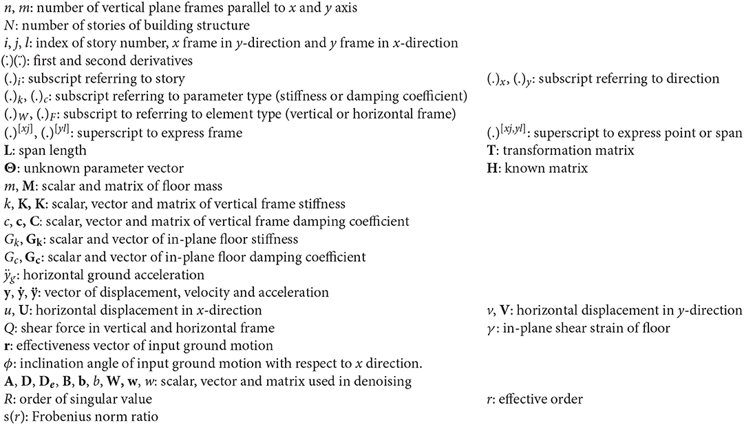
Symbols
Appendix 1
Dynamic Equilibrium for Equation of Motion
The restoring shear forces , and damping shear forces , in the yl and xj vertical plane frames in the i-th story can be expressed by
Let denote the shear strain of floor related to the x and y direction relative deformation, respectively, as shown in Figure 1C.
The in-plane shear forces , due to the stiffness can be expressed by
Similarly, the in-plane damping shear force , -velocity relations can be expressed by
Figure A1 shows the schematic diagram of dynamic equilibrium at the intersection of the vertical frame and the horizontal frame. The equation of motions in the x direction for the i-th floor in the yl vertical frame and in the y direction for the i-th floor in the xj vertical frame can be expressed by
where and are defined as the sum of masses of the corresponding frames in the i-th floor.
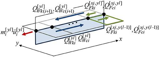
Figure A1. Schematic diagram of dynamic equilibrium at the intersection of vertical frame and horizontal frame (floor).
Appendix 2
Transformation Matrix for Physical Parameter System Identification
HW(t) defined in Equations (14) and (17) is a known {(n + m)N} × {(n + m)N} coefficient matrix related to vertical frame stiffness. HW(t) consists of N × N matrices (l = 1, …, n) and (j = 1, …, m) along diagonal. and are sub vectors in the (i-1, i)-th rows and the i-th column of and . and are related to , and can be expressed by
HF(t) defined in Equations (14) and (17) is a known {(n + m)N} × {(n − 1)(m − 1)N} coefficient matrix related to the in-plane floor stiffness. HF(t) consists of sub vectors existing at the four rows N(l − 1)+i, Nl + i, N(m + j − 1)+i, N(m + j)+i in {(n − 1)(m − 1)(j − 1) + (m − 1)(l − 1)+j}th column. is related to and can be expressed by
Keywords: system identification, torsional response, in-plane flexible floor, batch processing least-squares method, physical parameter identification
Citation: Shintani K, Yoshitomi S, Fujita K and Takewaki I (2019) Stiffness and Damping Identification for Asymmetric Building Frame With In-plane Flexible Floors. Front. Built Environ. 5:103. doi: 10.3389/fbuil.2019.00103
Received: 09 July 2019; Accepted: 20 August 2019;
Published: 10 September 2019.
Edited by:
Ehsan Noroozinejad Farsangi, Graduate University of Advanced Technology, IranReviewed by:
Abbas Sivandi-Pour, Graduate University of Advanced Technology, IranFrancisco López Almansa, Universitat Politecnica de Catalunya, Spain
Copyright © 2019 Shintani, Yoshitomi, Fujita and Takewaki. This is an open-access article distributed under the terms of the Creative Commons Attribution License (CC BY). The use, distribution or reproduction in other forums is permitted, provided the original author(s) and the copyright owner(s) are credited and that the original publication in this journal is cited, in accordance with accepted academic practice. No use, distribution or reproduction is permitted which does not comply with these terms.
*Correspondence: Izuru Takewaki, takewaki@archi.kyoto-u.ac.jp
 Kenichirou Shintani1
 Shinta Yoshitomi
 Kohei Fujita
 Izuru Takewaki