 Dario De Domenico
 Giuseppe Ricciardi
 Samuele Infanti2
94% of researchers rate our articles as excellent or good
Learn more about the work of our research integrity team to safeguard the quality of each article we publish.
Find out more
ORIGINAL RESEARCH article
Front. Built Environ., 04 June 2019
Sec. Earthquake Engineering
Volume 5 - 2019 | https://doi.org/10.3389/fbuil.2019.00074
This article is part of the Research TopicRecent Advances and Applications of Seismic Isolation and Energy Dissipation DevicesView all 19 articles
The hysteretic behavior of friction isolators is affected by the variability of the friction coefficient caused by heating phenomena at the sliding interface. The aim of this paper is to investigate such heating phenomena through a series of full-scale experimental tests on a double curved surface slider. The prototype isolator is equipped with eight thermocouples placed in different points of the isolator, which are embedded in the sliding plate. The probes of the thermocouples are in contact with the stainless steel sheet covering the sliding plate, in such a manner that their measurements are representative of the temperature rise occurring at the sliding interface. By investigating different axial loads and sliding velocities, we discuss the measured temperature rise and its implications on the hysteretic behavior of the prototype isolator. Friction variation is observed in the cyclic response of the isolator, which reduces the energy dissipated per cycle and, consequently, may lead to some underestimations of the displacements occurring during real seismic events if a constant friction coefficient is assumed. The proposed data can be helpful to calibrate sophisticated thermo-mechanical finite element models, which is the object of ongoing research.
Curved surface sliders (CSS), also known as friction pendulum isolators, are seismic isolation devices that have been increasingly used as effective earthquake protection strategy of buildings and bridges. The pendulum operating principle is offered by an articulated slider moving along a concave surface, and the restoring capability is due to the curved geometry of the sliding surface itself. The popularity of these devices is mainly due to the large displacement capability, besides the compact shape, especially for improved versions with multiple sliding surfaces like double (Fenz and Constantinou, 2006), triple pendulum system (Sarlis and Constantinou, 2013), and the lower thickness in comparison with the elastomeric devices. The imposed natural period of vibration is controlled by the sliding surface radius, thus it is not affected by the supported mass, which results in an ideal coincidence of the center of mass and center of stiffness. The energy dissipation is uniquely dependent upon the tribological properties of the sliding materials. Typical materials employed in practice include Polytetrafluoroethylene (PTFE) composites, Ultra High Molecular Weight Polyethylene (UHMWPE), and Polyammide (PA).
Experimental findings reveal that the friction coefficient of these isolators is far from being constant during an earthquake event (i.e., complying with the Coulomb's law of friction). In reality, the friction coefficient is variable, and it may be considered as a complex function of axial load, sliding velocity, and heating phenomena at the sliding interface, which may lead to significant friction variation. The friction properties may strongly affect the seismic performance of base-isolated structures (Castaldo and Tubaldi, 2015). Among the above effects, the primary and most important source of variation of the friction coefficient is the temperature rise arising at the sliding surfaces. Friction-induced temperature rise and consequent variation of the friction coefficient are two interconnected phenomena that affect one another and that, consequently, should be carefully considered to assess the actual hysteretic characteristics of these isolation devices. Nevertheless, experimental investigations focused on the mutual interaction between mechanical and thermal behavior are very few (Constantinou et al., 2007; Quaglini et al., 2014). Moreover, available experimental results refer to just few excitation scenarios (not exploring the variability of the temperature rise with different sliding velocity and axial loads) and are limited to single CSS. Additional experimental results that correlate the temperature rise at the sliding interface with the corresponding hysteretic behavior are desirable for a proper understanding of the complex thermo-mechanical response of friction isolators.
The aim of this paper is to complement the previous experimental studies by considering a more general testing scenario. In this work, a double curved surface slider (DCSS) is tested under different monodirectional excitations (including five sliding velocities and two levels of vertical load) at the laboratory CERISI of the University of Messina, Italy. In line with previous experimental campaigns, temperature measurements are obtained through eight thermocouples embedded into the upper plate of the device, at a certain depth below the sliding interface. The mechanical and thermal response of this device is monitored experimentally. The recorded force-displacement curves and the thermocouple registrations could be useful to calibrate new thermo-mechanical models (for instance, based on finite elements) or to validate existing analytical/numerical models available in the literature (Lomiento et al., 2013a,b; Kumar et al., 2015; De Domenico et al., 2018; Furinghetti et al., 2019; Gandelli et al., 2019) against experimental findings, which is left for future research work.
We here recall the basics of the mechanical behavior of friction isolators focusing the attention on the frictional performance. A sketch of a DCSS is shown in Figure 1 along with a schematic diagram of the corresponding force-displacement response. The device consists of a slider (typically made of steel), whose external surfaces are convex and equipped with two pads of a specific sliding material. The most widely used sliding materials are polytetrafluoroethylene (PTFE), PTFE-based composites enhanced with fillers, or self-lubricating polymers with high-bearing capacity such as ultra-high-molecular-weight polyethylene (UHMWPE). Above and below the slider there are two steel plates, whose internal surfaces are concave with the same curvature radius as the inner pads and are covered by a sheet of polished stainless steel (typically 2.5 mm thick).
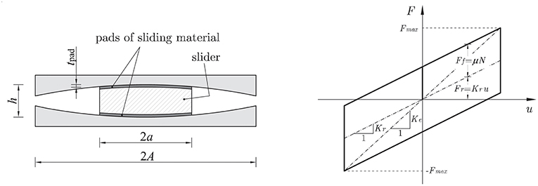
Figure 1. Sketch of a double curved surface slider (Left) and schematic force-displacement response (Right).
When the slider departs from the original (equilibrium) position, the sliding motion along with the curvature of the surfaces give rise to a resisting force F. In particular, the mechanical behavior of the device is controlled by two main characteristics: (1) the curvature radius R of the two opposed pairs of curved surfaces (one concave and one convex); (2) the tribological properties of the sliding materials at the interface. Indeed, the curvature radius R affects the re-centering properties of the device according to the pendulum principle (re-centering force Fr), in relationship with the value of the axial load N (i.e., the gravity load of the supported mass) and the entity of the displacement magnitude u. On the other hand, the frictional force Ff arises due to the sliding motion and is ideally independent on the value of the displacement, but mainly related to the friction coefficient μ and to the signum of the sliding velocity v. The mathematical model describing the idealized bilinear hysteretic behavior shown in Figure 1 is the following (Zayas et al., 1990).
where W is the applied vertical load acting on the device, Kr = W/R represents the restoring stiffness and sign(·) is the signum function. According to Equation 1 that assumes a constant friction coefficient, the frictional force is Ff = ±μW depending on whether the sliding velocity is positive or negative, respectively. Therefore, the bilinear hysteretic behavior of the device stems from the sum of two contributions, the restoring force Fr and the frictional force Ff.
In contrast to the assumption of constant friction coefficient underlying Equation 1, the value of μ evolves during a real seismic event as observed in experiments. In order to highlight the real variability of the friction coefficient due to different effects, the restoring force Fr can be subtracted by experimental measures of the total force of the device F, and the resulting friction force (evolving during the test) can be divided by the vertical load W to obtain the value of μ. Relevant results obtained at the CALTRANS SRMD laboratory at the University of California San Diego are depicted in Figure 2 for two different testing pressures, namely 15 and 30 MPa.
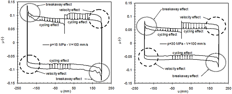
Figure 2. Variability of friction coefficient with pressure, velocity, and cyclic effects (from Lomiento et al., 2012).
The Coulomb friction model would lead to a rectangular friction coefficient-displacement cycle, whereas the experimental loop departs significantly from this idealized rectangular shape. The main sources of variability of the friction coefficients are ascribed to the following aspects:
• Breakaway effects due to the transitions between the static and dynamic values of the friction coefficients that occur at the beginning of motion and at each motion reversal;
• Pressure effects as the friction coefficient decreases with increasing vertical loads; for instance, the two values of applied pressures lead to friction coefficients of around 0.08 (for p = 15 MPa) and 0.05 (for p = 30 MPa);
• Velocity effects as the friction coefficient is related to the velocity of motion; it decreases with reduction of speed and this can be observed before the motion reversals by inspection of the rounded shape of the cycle near the attainment of the peak displacement values, wherein the velocity decreases down to zero;
• Cycling effects as the friction coefficient decreases with repetition of cycles; this is due to heating phenomena arising at the sliding interface that induce temperature rise and friction variation. This work is mainly focused on the cycling effects, which are significant especially for high-velocity tests and for high contact pressures.
Based on these experimental observations, the frictional force Ff entering Equation 1 should be considered as a complex function of vertical load, sliding velocity, and temperature rise at the sliding interface as follows
Such a model can only be calibrated based on extensive experimental data that investigate the temperature rise at the sliding interface for different vertical loads and sliding velocities. The present experimental work aims to provide a series of test results (temperature measurements and force-displacement loops) for a full-scale DCSS prototype that can be helpful to develop such complex models of friction variability.
A full-scale prototype of double curved surface slider has been tested at the laboratory CERISI of the University of Messina, Italy (see Figure 3), whose main geometrical and mechanical characteristics are summarized in Failla et al. (2015).
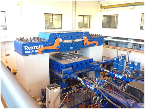
Figure 3. Photograph of the laboratory CERISI, University of Messina, Italy.
The main geometrical properties of the device are listed in Table 1. The design load for the isolator is, according to the manufacturer's specifications, equal to 4,357 kN, which corresponds to the highest value of load used in the testing protocol. The sliding material is a particular type of UHMWPE developed by the company FIP Mec S.p.A., whose trademark name is FFM (Fip Friction Material) type M (medium friction, corresponding to a minimum friction coefficient of 5.5%), which is characterized by high compressive strength, excellent wear resistance and good stability and durability properties. The material is used in a non-lubricated variant and, compared to PTFE alternatives, exhibits negligible stick-slip phenomena and is characterized by a very low ratio between the breakaway and the dynamic friction coefficient. The absence of significant breakaway phenomena at the beginning of motion has also been verified in a series of slow (quasi-static) tests performed at the laboratory CERISI on the DCSS prototype of the present experimental campaign, using triangular wave forms with constant velocity of 0.1 mm/s, in accordance with EN15129:2009 standards (CEN Comité Européen de normalisation TC 340, 2009) (whose results are not reported here for the sake of brevity). Other characteristics may be found in the manufacturer website https://www.fipindustriale.it/.
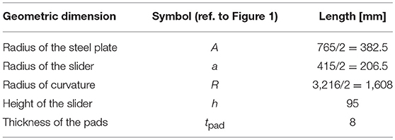
Table 1. Geometrical data of the analyzed double curved surface slider.
Before the tests, the upper plate of the DCSS prototype is CNC (computer numerical control) machined to create a set of holes that allow the installation of eight thermocouples, as documented in Figure 4. The drawings of the holes and photographs of the final configuration of the DCSS prototype are shown in Figure 5.
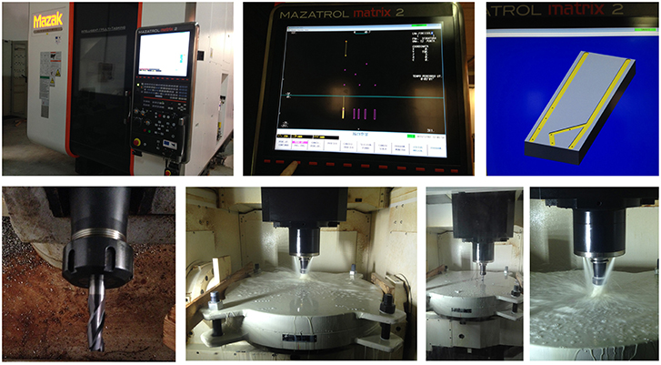
Figure 4. CNC machining of the DCSS prototype to create holes and routes for the thermocouple installation.
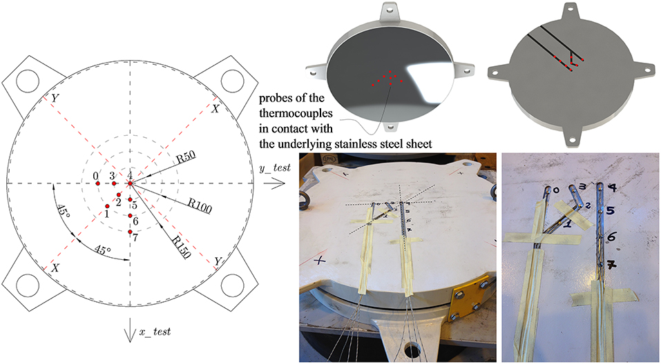
Figure 5. Preparation of the DCSS prototype with eight thermocouples embedded into the upper plate.
J-type thermocouples are used with conductors having dimensions 1/0.3 mm, tolerance in accordance with IEC 584 Class 2 and temperature range from −60°C to +350°C. The eight thermocouples are labeled from 0 to 7, which corresponds to the numbers of channels (CH) used for the acquisition of the temperature registrations. The thermocouples are installed in contact with the underlying polished stainless steel sheet of 2.5 mm thickness; therefore, their depth with respect to the sliding surface is exactly 2.5 mm, whereas their depth with respect to the top surface of the overlying steel plate depends on the considered thermocouple, and is 22.28 mm for thermocouple 4 (central), 23.04 mm for thermocouples 2, 3, and 5 (lying on a radius of 50 mm from the center), 25.31 mm for thermocouples 0, 1, and 6 (lying on a radius of 100 mm from the center) and 30.28 mm for thermocouple 7 (lying on a radius of 150 mm from the center). The difference in the thermocouple depths is due to the spherical curvature of the sliding surface, which is related to the radius 1,608 mm as reported in Table 1.
As shown in Figure 5, the thermocouples are embedded into the upper plate of the DCSS prototype and then special care has been taken in order to allow their conductors to come out from the device via two properly realized routes. The device is then installed in the testing equipment as can be seen in the photographs of Figure 6. The two routes through which the conductors pass are deep enough to prevent breakage of the wires when the upper plate is in contact with the overlying girder steel beam of the testing equipment and subject to the vertical load.
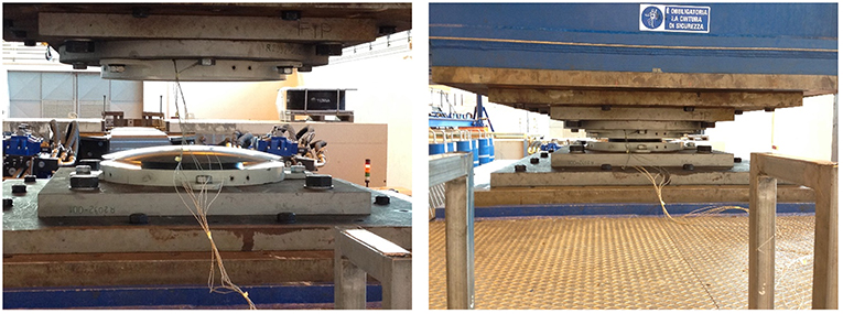
Figure 6. Installation of the DCSS prototype into the testing equipment, with thermocouple wires coming out from the two routes realized in the upper plate.
The testing protocol, listed in Table 2, comprises two bearing pressures (15 and 30 MPa) and five different sliding velocities. More specifically, the tests 1–10 consists of a sinusoidal displacement input of the form u(t) = umaxsin(2πf0) where f0 is the frequency and umax the maximum displacement. These tests have a maximum velocity vmax = 2πf0umax and an average velocity over a cycle vav = 4f0umax. The range of sliding velocities of the present experimental campaign has been chosen in line with similar research papers from the relevant literature (Furinghetti et al., 2019; Gandelli et al., 2019), considering the typical values of sliding velocities of commonly used devices and also the recommendations from the manufacturer of the DCSS prototype. Following (Gandelli et al., 2019), one cycle at low velocity (vmax ≤ 25 mm/s), two cycles in the medium velocity (40 ≤ vmax ≤ 100mm/s) and two cycles in the high velocity range (vmax ≥ 200mm/s) are included in the testing protocol. The same sliding velocities investigated in Furinghetti et al. (2019) for a similar experimental work have been adopted, namely 10, 40, 100, 200, 400 mm/s. These tests have allowed us to investigate the heating phenomena for different testing scenarios ranging from small contact pressures in conjunction with slow sliding motion up to more severe excitations associated with higher contact pressured in combination with higher sliding velocities. It is reasonably expected that the temperature rise is more pronounced for the latter testing conditions, as the heat flux q (power dissipated per unit area) can be ideally expressed by the following formula (Lomiento et al., 2013b; De Domenico et al., 2018).
thus increasing linearly with the vertical load W and the sliding velocity v.
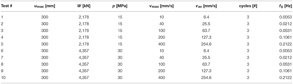
Table 2. Testing protocol of the DCSS prototype.
It is worth noting that the sinusoidal displacement has been imposed along the x_test axis for all tests except for test #5 that has been carried along the y_test axis (cf. left-hand side of Figure 5) owing to some safety reasons on the testing equipment capabilities (related to the lower consumption of oil of the horizontal actuators along the y_test axis). This is important to interpret the temperature measurements of the eight thermocouples in relationship with their position in plan, since the thermocouples 4-5-6-7 are aligned with the x_test axis, whereas the thermocouples 4-3-0 are aligned with the y_test axis.
For the sake of brevity, only a limited set of results of the testing protocol listed in Table 2 are here presented and discussed. In particular, tests #2 and #7 (corresponding to maximum sliding velocities of 40 mm/s) have been selected as representative situations in which the heating phenomena are not pronounced, therefore the modest temperature rise does not lead to a significant friction variation. On the other hand, tests #5 and #8, associated with higher sliding velocities, do produce a friction variation owing to the heating phenomena occurring at the sliding interface. Results from test #10 are not shown because they were affected by an experimental problem during the force recording process.
The force-displacement loops of the tests #2 and #7 are shown in Figure 7. As can be seen, the three cycles are almost superimposed to one another, with no significant difference between the first and third loop. This indicates that the friction coefficient is not affected by the temperature rise occurring in these tests and is quite stable during repetition of cycles (i.e., no considerable cycling effects take place). It is worth noticing some little deviations from the ideal force-displacement loop at the motion reversal (more evident in test #7). These may be ascribed to the concurrent effects of slightly varying vertical load induced by the vertical actuators (at the maximum excursion point of the slider), which are however limited to within the admissible values of the EN15129:2009 standards (CEN Comité Européen de normalisation TC 340, 2009), and the change of sliding velocity. The corresponding temperature values of the eight thermocouples are shown in Figure 8 for both tests #2 and #7. It is observed that the maximum temperature measured during the test #2 does not exceed 35°C while the maximum temperature for test #7 is slightly higher than 42°C. The higher temperature in test #7 in comparison with test #2 (at the same maximum sliding velocity) is due to the higher contact pressure (p = 30 MPa in test #7 vs. p = 15 MPa), which corresponds to a doubled heat flux, cf. again Equation 1. However, there is a contemporaneous mechanism of “thermal control of friction,” which makes the corresponding temperature rise not scaled proportionally with the heat flux (Ettles, 1986).
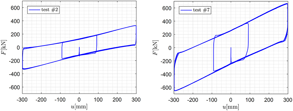
Figure 7. Force-displacement loops of the DCSS prototype for test #2 (Left) and test #7 (Right).
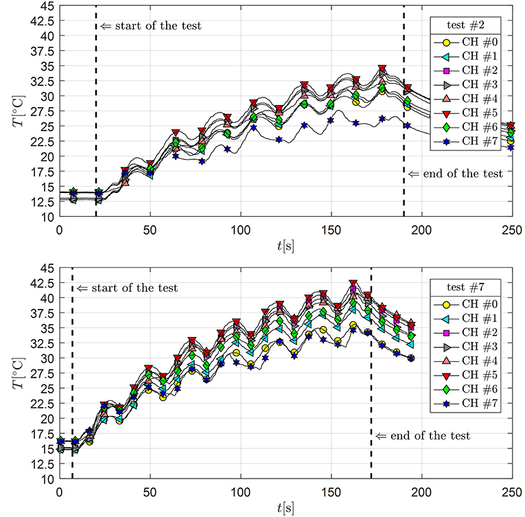
Figure 8. Temperature measurements of the eight thermocouples for test #2 (Top) and test #7 (Bottom).
By inspection of the different temperature measurements of the eight channels (CH #0–CH #7), it can be noted that the highest temperature value occurs at the CH #5. The thermocouple five is indeed placed along the x_test axis and is probably the one associated with the more frequent sliding activity. Interestingly, the fluctuations of temperature are of short duration and therefore the corresponding temperature rise is called flash temperature in the relevant literature (Stachowiak and Batchelor, 2005).
Friction variation is instead observed in more severe testing excitations. In Figure 9, we show the force-displacement loops corresponding to test #5 and test #8. Especially for test #5, it is seen that the loops are narrowing after repetition of cycles, which is due to the friction variation induced by the temperature rise.
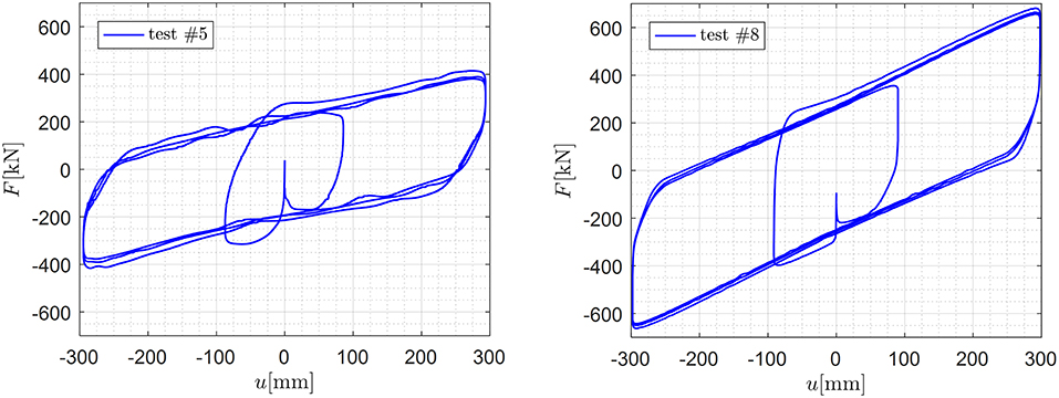
Figure 9. Force-displacement loops of the DCSS prototype for test #5 (Left) and test #8 (Right).
By examining the corresponding temperature measurements for the two tests shown in Figure 10, peak temperature values of around 70°C in test #5 (with maximum sliding velocity of 400 mm/s) are obtained. Once again, the thermocouple associated with the highest value of the temperature is CH #5. However, in contrast to other tests performed along the x_test axis, in the test #5 the thermocouple CH #6 is associated with higher temperature values than the other tests. A possible justification is due to the fact that the sliding motion in test #5 is directed along the y_test axis (horizontal axis in the plan view of Figure 5) rather than along the x_test axis. Therefore, the thermocouple CH #6 is placed along the peripheral part of the slider perpendicular to the direction of the sliding motion, where the highest values of the contact pressure are expected to take place. This is in line with trends of contact pressures identified in finite element analysis, cf. Figure 11, as well as in experimental tests through the aid of pressure-sensitive films placed between the sliding pad and the stainless steel sheet (Furinghetti et al., 2019). Moreover, the thermocouple CH #6 is crossed when the displacement of the device is zero and the corresponding velocity is maximum, therefore a large amount of heat flux (as a combination of pressure and velocity) is transferred based on Equation 1.
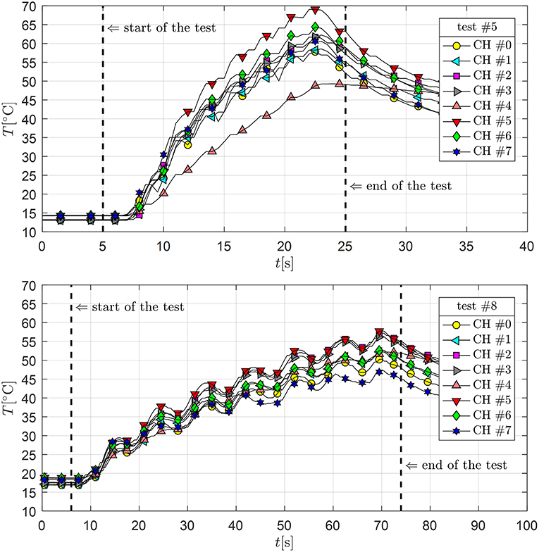
Figure 10. Temperature measurements of the eight thermocouples for test #5 (Top) and test #8 (Bottom).
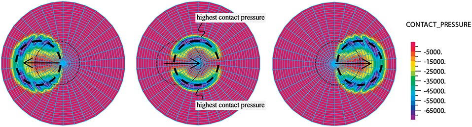
Figure 11. Contour plots of contact pressure of CSS prototype analyzed in De Domenico et al. (2018).
By observing the bottom part of Figure 10, the maximum temperature is slightly lower than 60°C in test #8 (with maximum sliding velocity of 100 mm/s). This fact, in combination with the previous results obtained in tests #2 and #7, indicates that the considered sliding material (UHMWPE) does not provide relevant friction variations for temperature rise up to ΔT = 45°C. A summary of the maximum temperature rises (with respect to the initial value of temperature at the beginning of the test) measured by the eight channels (eight thermocouples) in the considered tests #2, #5, #7, #8 is reported in Table 3.
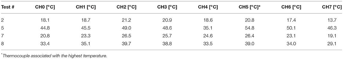
Table 3. Maximum temperature increase measured by the eight thermocouples in the tests #2, #5, #7, #8.
A specific proposal of analytical or numerical model accounting for the friction variation due to the heating phenomena is beyond the scope of the present paper. However, we recall that in a previous paper by the authors (De Domenico et al., 2018) a phenomenological (analytical) model was presented to capture the effects of frictional heating on the hysteretic behavior through a macroscale cycling variable. Moreover, in the same paper a thermo-mechanical coupled finite element model was also developed and validated against experimental data recorded in full-scale tests of CCS. A FORTRAN subroutine was developed to adjust the local friction coefficient based on the specific temperature value from the thermal solution. Nevertheless, in the previous work, no direct temperature measurement was performed, but the parameters of the subroutine were calibrated in an indirect fashion, based on the macroscopic force-displacement loops and, consequently, the resulting hysteretic behavior. What we aim to do in a forthcoming study is to exploit the actual temperature registrations here determined through the eight thermocouples to calibrate the above numerical model in a more consistent and physically meaningful manner.
We limit ourselves to point out the main consequences of the friction variation occurring in more severe tests (like #5 and #8) in terms of the main hysteretic parameters, namely the energy dissipated per cycle (EDC), and the dynamic friction coefficient per cycle μdyn computed as
wherein the average maximum displacement uav is equal to (umax − umin)/2, with umax and umin the maximum (positive) and minimum (negative) displacement in each cycle. Finally, the average maximum force Fav is calculated as
wherein Fmax and Fmin denote the maximum (positive) and minimum (negative) force in each cycle. Corresponding values of EDC, μdyn and Fav for the tests #5 and #8 are listed in Table 4, from which we note that the friction variation in test #5 leads to a reduction of 12.7% in terms of EDC and in terms of μdyn by comparing the first and third cycle. Similarly, the friction variation in test #8 leads to a reduction of 8.1% in terms of EDC and in terms of μdyn by comparing the first and third cycle. Moreover, we verify the variation of μdyn and Fav with respect to the mean value obtained from the three cycles by computing the variation values for the ith cycle as follows:
with x = EDC, Fav. From the values reported in Table 4 we notice that the DCSS prototype provided friction variations below ±8% of the mean value. In line with the prescriptions of the EN15129:2009 standards (CEN Comité Européen de normalisation TC 340, 2009), in computing these variations only the three full cycles are considered, i.e., the starting and ending branches are excluded, although these branches are considered in the temperature measurements reported above. The presented results are useful for the calibration of a numerical model, which is the object of ongoing research.
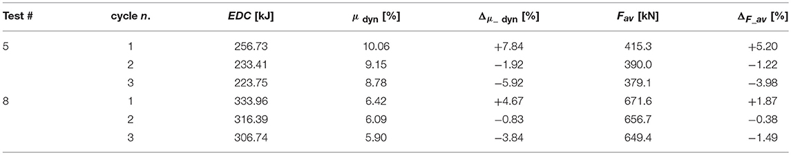
Table 4. Hysteretic parameters corresponding to two tests with friction variation.
This paper has focused on the temperature rise of friction isolators, with particular emphasis on a double curved surface slider prototype that has been analyzed through full-scale experimental tests at the laboratory CERISI of the University of Messina, Italy. The device has been equipped with eight J-type thermocouples installed just below the stainless steel sheet in order to capture the temperature rise at the sliding interface. The thermocouples are placed on specific holes realized by a numerical control machine on the upper plate of the device. Five values of sliding velocities (in the range 10–400 mm/s) and two values of contact pressures (15 and 30 MPa) have been considered, in order to explore different thermo-mechanical responses of the DCSS prototype under a series of testing scenarios.
The results presented in this paper confirms that the temperature rise ΔT and the consequent cycling effects may affect the overall hysteretic behavior of full-scale friction isolators. However, the sliding material of the DCSS prototype used in the present experimental campaign, namely UHMWPE, is not significantly affected by temperature rise up to ΔT = 45°C, at least for the tests conducted in this experimental campaign. Values of peak temperature of around 70°C have led to a certain reduction of the force-displacement loops, with a consequent reduction of the EDC and of the friction coefficient of a bit more than 12% when comparing the third cycle with the first cycle under imposed sinusoidal displacement tests. These variations are, however, modest (not significant) if compared to the implied uncertainties of the mechanical behavior of DCSS, the manufacturers' accuracy in defining the friction coefficient, and the approximate formulas used in the seismic codes. It is worth noting that the conclusions drawn here are limited to the employed UHMWPE as sliding material. Experimental force-displacement curves relevant to similar testing conditions (i.e., comparable sliding velocity and contact pressure) performed on a DCSS prototype with PTFE as sliding material (in place of UHMWPE of the present experimental campaign) showed significantly more marked reductions of the force-displacement curves (Furinghetti et al., 2019) than the ones reported in this paper and, by inference, a more pronounced influence of the heating phenomena on the friction coefficient. Finally, in tests involving slow sliding velocities or less severe combinations of sliding velocities and contact pressures, associated with temperature rise ΔT in the range from 25 to 45°C, no friction variation at all has been observed and the force-displacement loops are quite similar during repetition of cycles.
In the authors' opinion, the experimental findings of the present campaign can be useful to calibrate analytical models (like phenomenological models) that account for the friction variation via variables that are only indirectly related to the temperature rise (Lomiento et al., 2013b; Furinghetti et al., 2019; Gandelli et al., 2019). Additionally, the punctual temperature measurements of the eight thermocouples may be important to calibrate and validate more sophisticated thermo-mechanical coupled finite element models that explicitly solve the thermal problem and the mechanical problem in an interconnected manner (Pantuso et al., 2000; Quaglini et al., 2014; De Domenico et al., 2018), which is left for future research work.
All datasets generated for this study are included in the manuscript and/or the supplementary files.
DD carried out the experimental tests, post-processed the results, and wrote the paper. GR planned the CNC machining activities and the experimental tests. SI reviewed the manuscript and contributed to integrating section Results and Discussion. GB supervised the entire research work.
SI is employed by company Fip Mec S.p.A.
The remaining authors declare that the research was conducted in the absence of any commercial or financial relationships that could be construed as a potential conflict of interest.
DD and GR would like to express their gratitude to the company FIP MEC for providing the DCSS prototype used for the present experimental campaign.
Castaldo, P., and Tubaldi, E. (2015). Influence of FPS bearing properties on the seismic performance of base-isolated structures. Earth Eng. Struct. Dyn. 44, 2817–2836. doi: 10.1002/eqe.2610
CEN Comité Européen de normalisation TC 340 (2009). European Code UNI EN 15129:2009 Anti-seismic Devices. Brussels: European Committee for Standardization.
Constantinou, M. C., Whittaker, A. S., Kalpakidis, Y., Fenz, D. M., and Warn, G. P. (2007). Performance of Seismic Isolation Hardware Under Service and Seismic Loading [Report MCEER-07-0012]. Buffalo, NY.
De Domenico, D., Ricciardi, G., and Benzoni, G. (2018). Analytical and finite element investigation on the thermo-mechanical coupled response of friction isolators under bidirectional excitation. Soil Dyn. Earthq. Eng. 106, 131–147. doi: 10.1016/j.soildyn.2017.12.019
Ettles, C. M. M. (1986). Polymer and elastomer friction in the thermal control regime. ASME J. Tribol. 108, 98–104. doi: 10.1115/1.3261151
Failla, I., Fazzari, B., Ricciardi, G., and Stella, A. (2015). “The Eurolab anti-seismic device (ASD) test facility at the University of Messina – Italy,” in Proceedings of the 14th World Conference on Seismic Isolation (14WCSI) (San Diego, CA).
Fenz, D. M., and Constantinou, M. C. (2006). Behaviour of the double concave friction pendulum bearing. Earthq. Eng. Struct. Dyn. 35, 1403–1424. doi: 10.1002/eqe.589
Furinghetti, M., Pavese, A., Quaglini, V., and Dubini, P. (2019). Experimental investigation of the cyclic response of double curved surface sliders subjected to radial and bidirectional sliding motions. Soil Dyn. Earthq. Eng. 117, 190–202. doi: 10.1016/j.soildyn.2018.11.020
Gandelli, E., Penati, M., Quaglini, V., Lomiento, G., Miglio, E., and Benzoni, G. M. (2019). A novel OpenSees element for single curved surface sliding isolators. Soil Dyn. Earthq. Eng. 119, 433–453. doi: 10.1016/j.soildyn.2018.01.044
Kumar, M., Whittaker, A. S., and Constantinou, M. C. (2015). Characterizing friction in sliding isolation bearings. Earthq. Eng. Struct. Dyn. 44, 1409–1425. doi: 10.1002/eqe.2524
Lomiento, G., Bonessio, N., and Benzoni, G. (2012). “Effects of loading characteristics on the performance of sliding isolation devices,” in Proceedings of the 15th World Conference on Earthquake Engineering.
Lomiento, G., Bonessio, N., and Benzoni, G. (2013a). Concave sliding isolator's performance under multi-directional excitation. Ingegneria Sismica 30, 17–32.
Lomiento, G., Bonessio, N., and Benzoni, G. (2013b). Friction model for sliding bearings under seismic excitation. J. Earthq. Eng. 17, 1162–1191. doi: 10.1080/13632469.2013.814611
Pantuso, D., Bathe, K. J., and Bouzinov, P. A. (2000). A finite element procedure for the analysis of thermo-mechanical solids in contact. Comput. Struct. 75, 551–573. doi: 10.1016/S0045-7949(99)00212-6
Quaglini, V., Bocciarelli, M., Gandelli, E., and Dubini, P. (2014). Numerical assessment of frictional heating in sliding bearings for seismic isolation. J. Earthq. Eng. 18, 1198–1216. doi: 10.1080/13632469.2014.924890
Sarlis, A. A., and Constantinou, M. C. (2013). Model of Triple Friction Pendulum Bearing for General Geometric and Frictional Parameters and for Uplift Conditions [Report MCEER-13-0010]. Buffalo, NY.
Stachowiak, G. W., and Batchelor, A. W. (2005). Engineering Tribology. Dordrecht: Elsevier Butteworth-Heinemann.
Keywords: curved surface slider, friction pendulum isolator, heating phenomena, friction variation, temperature measurements
Citation: De Domenico D, Ricciardi G, Infanti S and Benzoni G (2019) Frictional Heating in Double Curved Surface Sliders and Its Effects on the Hysteretic Behavior: An Experimental Study. Front. Built Environ. 5:74. doi: 10.3389/fbuil.2019.00074
Received: 11 April 2019; Accepted: 20 May 2019;
Published: 04 June 2019.
Edited by:
Massimo Latour, University of Salerno, ItalyReviewed by:
Yutaka Nakamura, Shimane University, JapanCopyright © 2019 De Domenico, Ricciardi, Infanti and Benzoni. This is an open-access article distributed under the terms of the Creative Commons Attribution License (CC BY). The use, distribution or reproduction in other forums is permitted, provided the original author(s) and the copyright owner(s) are credited and that the original publication in this journal is cited, in accordance with accepted academic practice. No use, distribution or reproduction is permitted which does not comply with these terms.
*Correspondence: Dario De Domenico, ZGFyaW8uZGVkb21lbmljb0B1bmltZS5pdA==
Disclaimer: All claims expressed in this article are solely those of the authors and do not necessarily represent those of their affiliated organizations, or those of the publisher, the editors and the reviewers. Any product that may be evaluated in this article or claim that may be made by its manufacturer is not guaranteed or endorsed by the publisher.
Research integrity at Frontiers
Learn more about the work of our research integrity team to safeguard the quality of each article we publish.