- 1Institute of Structural Analysis & Antiseismic Research, Department of Structural Engineering, School of Civil Engineering, National Technical University of Athens, Athens, Greece
- 2Green Innovation & Vehicle Engineering, Attica Technology Park Lefkippos, NCSR Demokritos, Athens, Greece
Weight reduction has always been a challenge for the automotive industry, mainly to reduce consumption but also improve handling. In electric vehicle design, the battery packs, their shape and positioning are critical aspects that determine the overall weight, weight distribution and, as a consequence, the efficiency, dynamics and stability of the vehicle. This presented a new challenge, to manage this necessary and inflexible weight and volume, developing the vehicle chassis around it and in the best possible way, without compromising the overall efficiency and behavior. In this work, a methodology for nested topology optimization has been developed which combines structural topology optimization and battery pack shaping and positioning. The new methodology is implemented without limiting its applicability, into the framework of the commercial software Hyperstudy by Altair.
Introduction
One of the major challenges in automotive industry is to continuously reduce weight and material cost, while preserving the same functional characteristics. The concept of light-weighting by means of optimization algorithms (Lagaros, 2014, 2018) has become vital in the last decade having significant impact in automotive industry especially with the increased number of manufacturing processes used to develop parts, such as machining, forging, stamping, and additive manufacturing techniques. Especially with the revolution of additive manufacturing (AM), the possibilities it unveiled and the design freedom it allowed, optimization methods have proved to be a powerful tool for designers leading to very interesting results and optimal structures. The main advantage of AM is the ability to handle complex optimized geometries and also in comparison, with cast, forged and stamp techniques negates special tooling which could be very expensive and time consuming to produce (Gibson et al., 2010). AM combined with topology optimization accelerates part construction and keep the material usage in its lowest possible level (Kazakis et al., 2017).
Topology however, deals only with the fulfillment of certain constraints which are connected to structural requirements of the chassis and chassis manufacturability and ignores parameters of vehicle design, such as component positioning, vehicle dynamics weight distribution etc. This can often lead to difficult data communication between different engineering teams and introduce delays in the product development cycle. In order to bridge the gap during the development of a new vehicle, structural engineers perform multiple redesigns and chassis adjustments, to accommodate peripheral vehicle's parts, their characteristics and optimum fit. This effect is magnified with heavier and more voluminous parts, such as battery packs, drivetrain components, seats, etc. which plays a crucial role in the design of a vehicle and their positioning directly affects performance and functionality.
A novel nested structural topology optimization framework is proposed in the current study aiming to overcome this obstacle, facilitate the design process and significantly reduce time. Topology optimization initiates from a bounded material volume, which represents the design space for the process. The adoption of a geometry as simple as possible is very important to achieve a regular high quality mesh (Barbieri et al., 2017). Inside this design space, there are specific areas having important functional and ergonomical characteristics. These areas will be excluded from the design process and constitute the non-optimizable space. In addition, the topology problem is concerned with the structural response of the system (load paths) given the design space, boundary conditions and constraints. Two types of constraints are used in this study, the first type of constraints (displacement constraints) are connected to structural requirements of the chassis, such as longitudinal-lateral-torsional stiffness and seat deflection. The second type of constraints (manufacturing constraints) is connected with chassis manufacturability including the checkerboard control, the minimum member size control, and the symmetry constraint.
The proposed framework includes input data regarding battery pack capacity, battery pack voltage and vehicle dynamics and conducts chassis topology optimization while simultaneously optimizing the vehicle's battery pack shape and positioning. In contrast to traditional engineering approaches, optimization fits between the conceptual design and the detailed design of the structure and provides the potential of a more sophisticated chassis development. The optimum design (with given limitations and constraints) was reached after 48 h approximately followed by satisfactory results.
Survey on Vehicle Design Optimization
The main objective of topology optimization is material distribution under performance constraints. A lighter vehicle will gain the ability to turn easier, accelerate faster and brake more efficiently (Cavazzuti and Splendi, 2012). Vehicle mass reduction plays a crucial role also important for safety (Cavazzuti et al., 2011). Less mass reduces the vehicle's kinetic energy and can maximize crashworthiness during collision. Furthermore, overall energy needs also reduce and as such, in the case of electric vehicles, can significantly improve the total vehicle's range.
Focused on vehicle light weighting, the use of topology in automotive applications gained interest the last two decades starting with simple vehicle structural components, such as truck frames, deck lids, space frame structures (Yang and Chahande, 1995), engine mounting brackets (Sudin et al., 2014), and similar structures, focused primarily in mass reduction, stiffness increase and cost saving. Evolution of the process extended the range of applications from simple structures to more complex and demanding structures, such as high performance automotive chassis (Cavazzuti et al., 2011; Cavazzuti and Splendi, 2012), which must fulfill precise automotive standards and optimization constraints like bending stiffness, torsional stiffness, modal response and crash linearization. In each case the use of topology provided useful hints to designers during the early development stages of innovative design concepts.
Further, topology found its way in smaller vehicle design, such as electric bicycles and bicycles chassis design. Wu and colleagues (Wu et al., 2003) explored the possible variations of frame design in city bicycles by using ergonomic measurements and topology optimization design, while Huang and Pan (2003) studied the structural topology of a bike frame with dumpers and especially the effect of topology optimization on joint locations in order to improve the dynamic behavior of the structure. Additionally, Xiao et al. (2012) generated a robust electric bicycle main frame by optimizing the material distribution under a multi dynamic load case and manufacturing constraints of minimum member size control and extrusion constraint. Optimized results were subjected to a modal analysis in order to validate topology optimization effectiveness through structural stiffness evaluation.
Similar studies examined isolated bicycles parts, such as the upper rocker of a mountain bike (Zeleny and Cadek, 2015). This optimized part obtained from topology optimization method and manufactured by Selective Laser Melting (SLM). In the same way isolated motorcycle parts like motorcycle swing arm (Powar et al., 2016), motorcycle front wheel (Joshi et al., 2016) and motorcycle piston (Barbieri et al., 2017) were developed or evolved with the usage of topology optimization techniques and additive manufacturing methods with maximum overall weight reduction between 24 and 44%.
In respect of chassis optimization, a study of a motorcycle frame structure was presented by Wang et al. (2012). The frame consisted of nine main components which were linked together, analyzed and optimized, the cost of motorcycle frame was reduced and weight was lightened about 6.5%. Nevertheless, this study had a multiple part approach and not a unified frame one. The most recent example which combines a study and a manufacturing process of a unified motorcycle chassis from scratch is the Airbus APWorks Light Rider (APWorks, 2018). This electric motorcycle has a total weight of 35 kg, with the frame alone weighting only 6 kg. Despite the minimal weight, the design meets all stiffness and natural frequency requirements. Light Rider combined topology optimization, a new high-performance aluminum alloy and metal 3D printing in order to produce an optimum lightweight design. The combination of these factors not only led to weight and cost savings, but also reduced assembly time significantly and helped integrate new additional functions in parts and components.
Topology Optimization and Solution Approach
Finite element-based topology optimization is a mathematical formulation that aims to optimize material layout with the goal of maximizing the performance of the system (Bendsøe and Kikuchi, 1988; Bendsøe and Sigmund, 2003). Optimal material distribution is being sought under specific loads, boundary conditions and constraints or alternatively topology optimization give answers to the fundamental engineering question: how to place material within a prescribed design domain in order to obtain the best structural performance (Sigmund and Maute, 2013)? Topology belongs to the broader category of constraint optimization problems. The most popular topology optimization constraints are mass, volume, displacement and stress. Moreover, stress-based constraints could also unlock a new fatigue constraint category as this described by Collet et al. (2017).
Application of this methodology is growing fast in the engineering community due to its key ability to produce innovative shapes during the conceptual design. Topology optimization provides a valuable perspective at the concept level of a design process and at preliminary design phases where multiple design ideas are being implemented in search of accepted performance. The method's range of applications extends from the automotive, aerospace, civil and naval engineering to bio-engineering, heat transfer, fluid flow, acoustics, materials design and other multi-physics disciplines (Lagaros et al., 2019). Despite the wide range of applications, the method frequently produces geometries which cannot be manufactured with classical methods. This gap between topology result and design for manufacturability (DFM) is still measurable due to the fact that topology optimization tends to lead to a non-smooth and complex structural geometry (Tang and Chang, 2001). However, the rapid growth of additive manufacturing technology is constantly closing this gap allowing for complex optimized parts to be made.
In the present study, the topology optimization part of the problem formulation is dealt with the SIMP approach (solid isotropic material with penalization). This density-based approach, is one of the most popular and widely used ones for structural topology optimization. The approach can be found in the literature as “material interpolation,” “artificial material,” or “power law,” with “SIMP” now being used fairly universally (Rozvany, 2009). In addition, SIMP has been evolved by Zuo and Saitou (2017) to solve not only single material but also multi-material topology optimization problems (Bendsøe and Sigmund, 2003).
In the SIMP approach (Bendsøe and Kikuchi, 1988; Zhou and Rozvany, 1991; Rozvany et al., 1992) the density of the actual isotropic material is considered as the design variable and intermediate density is penalized by relating the stiffness tensor of the material to the density with a power p larger than 1.0. The role of penalty parameter p is to make intermediate densities unfavorable in the optimized solution. For the SIMP approach the penalization is achieved by the following power law formulation:
where ke(xe) and represent the penalized and the original stiffness matrix of the eth element, respectively, and p is the penalization factor (Zhou et al., 2001).
Furthermore, hard-kill methods, including Evolutionary Structural Optimization (ESO), boundary variation methods (level set and phase field), and a new biologically inspired method based on cellular division rules seem to be also applied in topology optimization approach during the two last decades (Deaton and Grandhi, 2014).
Nested Topology Optimization Methodology
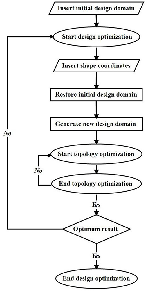
The nested methodology followed in this work is explained in Figure 1. The method was implemented using Hyperstudy software, a design exploration tool with multiple optimization algorithms provided by Altair Engineering.1 It begins from the insertion of an initial design domain, proceeds with a design optimization (external optimization) followed by topology optimization (internal optimization). During the first phase of the design optimization, shape coordinates are updated and inserted into the process. This shape was then used to reform the initial design domain. In the second phase and before domain reformation, the algorithm resets the design domain in its initial state, so each new reformation initiates from the same design. Finally, in the third phase, the inserted shape coordinates are used to form a new shape and exclude the enclosed elements from the design domain. This new generated domain is then used for the topology optimization. Once the topology ends, results (objective function) and constraints (shape) are evaluated and the process continues until convergence is achieved.
Internal Topology Optimization
The topology optimization was executed using OptiStruct's SIMP approach which penalizes intermediate densities and force the final design to be represented by densities of 0 or 1 for each element. Additional manufacturing constraints (see section Load Cases and Displacement Constraints) were introduced in order for the design concept to be manufacturable.
External Design Optimization
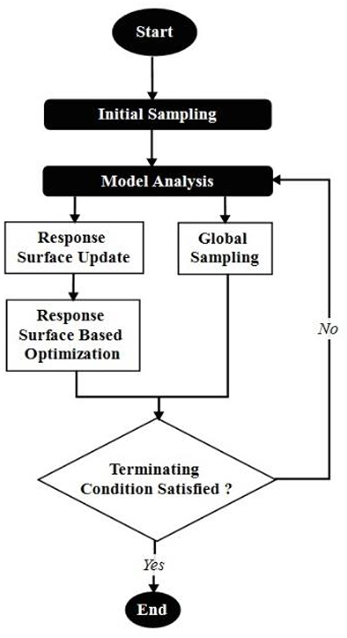
The external optimization process is based on the Global Response Surface Method or (GRSM) as described by Pajot (2013) and executed in HyperStudy. The GRSM algorithm searches for a global solution and is independent of local minimum/maxima phenomena associated with “gradient based” optimization methods. Gradient based methods develop a strong link to the original design, which enhances the possibility of locking the solution locally (Bartz-Beielstein et al., 2010). In contrast, GRSM uses a multi-start approach based on an initial sample with “N” designs to overcome this obstacle. Within the first iteration, a Design of Experiment or (DOE) is constructed internally to provide the data to construct an initial response surface. The initial number of designs in the present study equals to 7 in order to ensure a good balance between local and global search. All iterations beyond the initial step are similar. A new DOE is constructed using the optimal points from the previous iteration (Pajot, 2013). This DOE is executed and the adaptive response surface is updated to absorb the new design points. The optimization problem is solved again on the newly constructed response surface, with the optimal design feeding forward to the next iteration until termination. The GRSM algorithm belongs in the category of exploratory optimization, meaning that the method does not show the typical numerical convergence characteristics observed in other algorithms, such as gradient based systems. Consequently, the termination state is determined by reaching the maximum number of iterations (designs evaluation) defined by the user. The flow-chart below (Figure 2) illustrates GRSM main operation.
Tcl, Batch, and FEM Files Operation
The process of nested optimization and especially the external optimization process is based primarily on two new in-house code files developed (Tcl and Batch) making use of a HyperMesh (fem) which contains model geometry and can be updated in each external iteration and output files created from OptiStruct after the completion of the topology optimization.
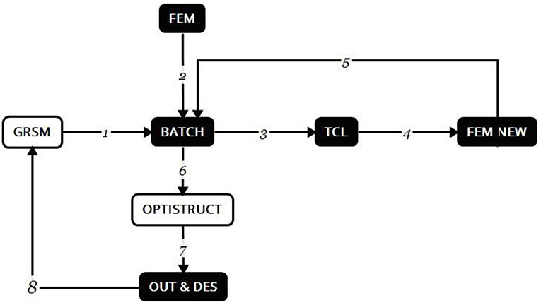
The process is explained in eight steps which demonstrate the main functionality of the algorithm, the connections between the different files and their overall coordination.
The steps are described below:
Step 1: GRSM algorithm calls the batch file which coordinates the process. File executed: Batch.
Step 2: Batch file retrieves data from the model, including information about the design space and non-design space, the computational grid, the boundary conditions and the data for the topology optimizer (objective function, responses, constraints, etc.). File used: Fem.
Step 3: Batch file calls a Tcl code responsible to create a new model. Files executed: Batch, Tcl.
Step 4: New model is created, in which elements have been removed according to the new shape. File created: Fem new.
Step 5: The process returns to the Batch code. File executed: Batch.
Step 6: Internal optimization process starts using OptiStruct. File used: Fem new.
Step 7: Two new files created that contain information about the displacements, the final mass and the optimum design shape. Files created: Out, Des.
Step 8: Results are fed back to the beginning and the GRSM algorithm that evaluates the design and decides on the continuation or termination of the process. Files used: Out, Des.
Inputs and outputs of Tcl and Batch files are presented in Table 1:
The above eight steps as well as the connection and dependence of the different code files are depicted in the following scheme (Figure 3).
Numerical Application
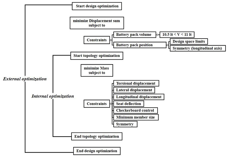
Two integrated optimization algorithms were enclosed in the presented nested structure. The minimization of the overall frame mass (together with additional manufacturing constraints) is defined as the internal optimization process whilst the minimization of the total displacements (the sum of the displacements of each load case described subsequently) as the external optimization process.
Where d1 is the torsional displacement, d2 is the lateral displacement, d3 is the longitudinal displacement and d4 refers to the seat deflection. The present application of the nested method is described in the following scheme (Figure 4). The initial design domain now represents the space from which the chassis will be formed while the battery pack represents the shape, which reforms the aforementioned domain in each iteration.
Chassis Shape Design
Initial Design Domain
A cad file for the two-wheel chassis was created and exported in iges format, a geometric clean up procedure followed (Figure 5) including redesign of complex surfaces (graphic design) and areas considered non-structural to avoid discretization abnormalities. The updated geometry was imported in HyperMesh followed by model preparation including meshing, required load and boundary conditions, manufacturing constraints, responses, objective function, etc.
Design Domain Discretization
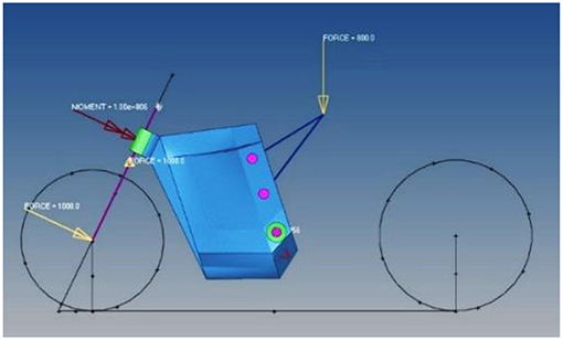
Chassis model was discretized using ~400,000 finite elements (see Table 2). During this process, 4 node tetrahedron elements were used for the design domain while rod and rigid body elements were used for applying boundary conditions and loads (see Figure 6).
Load Cases and Displacement Constraints
The frame was subjected to four different load cases (see Table 3) including a torsional, a lateral, a longitudinal and a case representing the driver's weight or seat deflection (Figure 6). For each of the load cases a maximum displacement constraint was set in order to limit the optimizer to solutions with the required structural frame stiffnesses.
Manufacturing Constraints
A crucial aspect taken into consideration in the present study was the level of manufacturability of the resulting design. As such, additional manufacturing constraints were applied to limit the solution range of the topology optimization problem and accelerate the design-to-prototype process. A scheme illustrating the relationship between manufacturing constraints and manufacturing techniques was presented by Vatanabe et al. (2016). The scheme shows the necessary constraints in order to generate compatible design for each technique. The figure emphasizes the important role of two constraints (symmetry constraint and minimum member size) in almost every manufacturing technique. Therefore, symmetry was used in order to reach a simplified and weight balanced frame design as well as minimum member size to prevent decreasing members formation due to numerical instabilities (mesh dependency). Finally, checkboard control was also used to overcome abnormal material distribution, especially as first order finite elements were used (Zhou et al., 2001).
Battery Pack Shape Design
During vehicle development specific goals of maximum speed and total range were set. The battery pack voltage and capacity (Table 4) determine the range of an electric vehicle's maximum speed and range. Preliminary design showed the necessary usage of ~504 (18650 Li-Ion) cells which are equal to a 10.84 lt. battery pack to cover the energy needs.
For computational purposes the predefined volume must be contained within adjacent bounds. This double inequality constitutes the first constrain of the external process.
The formula below presents the calculation of the volume from the 6 design variables which constitute the coordinates of two peaks.
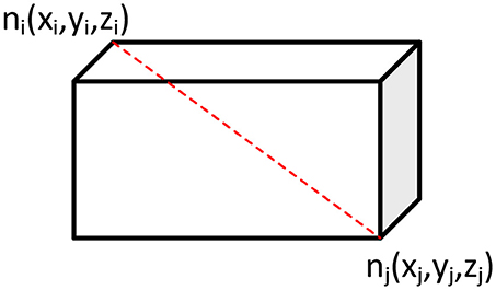
Being among the most expensive parts of an electric vehicle, batteries must be protected during a possible collision or stability loss. It is therefore essential for the battery pack to be fully surrounded from the chassis. Furthermore, the battery pack must be symmetrical with regard to the longitudinal axis for stability reasons. For the purposes of the present study, the battery pack was represented with a parallelepiped rectangular shape (see Figure 7) determined by nodes ni and nj. These two peaks had to remain inside the design domain to fulfill the second battery pack positioning constrain.
Nested Optimization Results
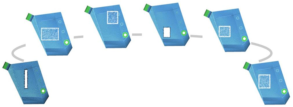
The results can be classified in two major categories. The first concerns the battery pack design optimization while design domain maintained unaffected. This allows a better understanding of battery pack adjustment through iterations. Figure 8 demonstrates the shape and positioning evolution from the initial to the optimal design formation. It is highlighted that battery pack design (white color borders), are entirely enclosed by the design domain.
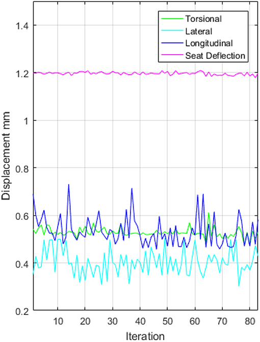
The second category demonstrates the combination of design and topology optimization. In the diagram below (Figure 9), the four displacement values corresponding to the load conditions (torsional, lateral, longitudinal and seat deflection) for each unique design are presented. It is noted that the displacement due to the load under seat deflection exhibits a steady behavior in comparison with the rest, which are being decreased. This behavior is connected with the magnitude of seat deflection force in comparison with others and also in the connection method (subframe insertion) with the main chassis.
The two diagrams below (Figure 10) presents the behavior of the objective function (sum of the four displacements-black color), which gradually decreases. It is observed that the objective function reaches a reverse plateau at iteration 36 (blue arrow) after 30 h. Considering time saving (~40 h) vs. results change, iteration 36 is set as the comparison point for the nested method. In addition, due to the selection of the respective DOE, the GRSM optimization algorithm is not expected to produce an objective function curve similar to those of a gradient-based method.
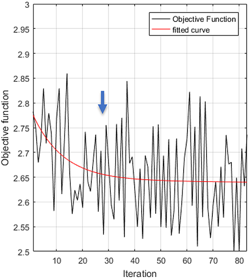
Figure 10. Nested optimization results: objective function and polynomial interpolation for 83 iterations.
Table 2 shows the results for the initial and optimum design until iteration 36. It can be observed that the mass of the chassis increases by ~1.2%, whilst the objective function, i.e., the deflection decreases by 9.35%. This result indicates that for a slight mass increase the value of the objective function simultaneously reduces significantly. Moreover, it is equally important to compare the change of the objective function in relation to the change of the polynomial interpolation curve. This method provides the ability to compare not only the extreme designs (worst vs. optimal) but also the intermediate designs, which shape the curve. It is observed that the change rate is reduced to half, from 9.35 to 4.69%, still being at an absolute value 4 times greater than the mass increase rate.
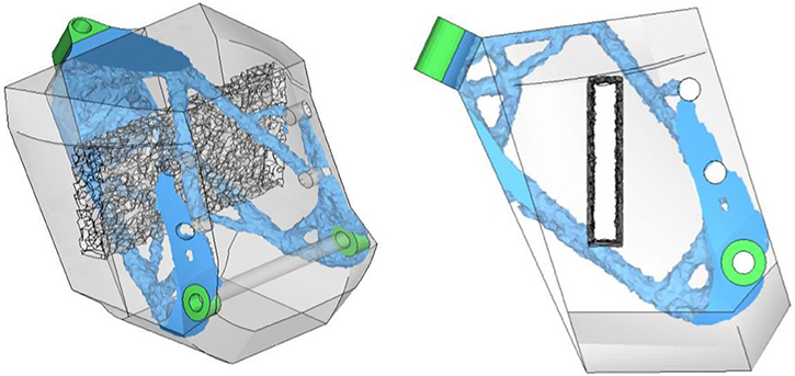
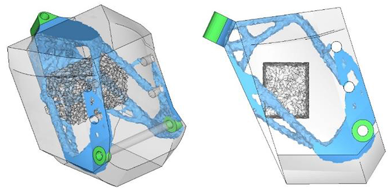
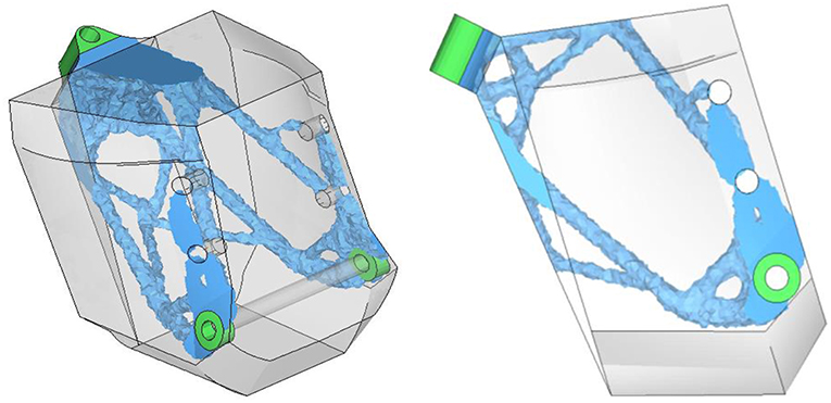
As indicated from Figures 11, 12 the initial and optimum chassis design (blue color) including the battery pack (darker gray-transparent color) covers a limited percentage of the initial design domain (gray-transparent color). More specifically, the initial mass including the non-design area mass (green color) of 302 kg was reduced to 44.37 kg, a reduction ~85.31% (Table 5).
Comparison of the Topology and Nested Optimization Results
In this section topology optimization results for mass minimization are compared with nested optimization results in order to get clear view of chassis development from the initial stage until optimum result. In the first stage of the present study, a simple mass minimization topology optimization took place, manufacturing constraints were added with succeed at the second stage and finally during stage three the nested optimization process was executed. Divided the study in the abovementioned stages provided the ability to evaluate each one in depth before final nested method development.
Table 6 presents the results of chassis development for the three stages. In stage two it is observed that the manufacturing constraints reduce the total mass by 2 kg, however the solution was more computationally expensive and each run was longer in comparison with stage one.
In addition to Table 6 results, Figures 13, 14 below depict difference in structural members width and material discontinuities between stage one and two. These differences are connected with manufacturing constraints import which added manufacturability to the final design, especially through checkboard control, minimum member size and symmetry constraints. These constraints should be taken into consideration by engineering team when the chassis is going to be inserted in a production line and tight time schedule must be kept.
Conclusions
A nested optimization process for developing a two-wheeled vehicle chassis is presented. The objective was to present an alternative process which combined structural, manufacturing and battery pack data in the design process. The main advantage of the method is located in electric vehicle chassis development acceleration by gathering all relevant data from different engineering subteams into one process. The methodology demonstrates the reformation of the design space before topology optimization to achieve optimum battery pack fitment while maintaining mass and stiffness in acceptable levels. However, due to large input data each new nested process must be constructed step by step in order to avoid constraints overlap or a possible conflict.
The process was implemented using a 3.2 GHz Xeon Quad-Core workstation in 30 h and provided a stiff chassis with an acceptable battery pack placement. Nevertheless, total time could be easily decreased to lower levels by using more computational power.
Design engineers should also show special care to initial design domain formation, which must be free of complex geometric shapes and surfaces. A smooth design accelerates domain discretization, finite element analysis and therefore topology optimization. It is highly noted that, initial design domain has a direct impact in topology optimization and can almost predefined the result through in advance material removal from specific areas.
Regarding the constraints of the external optimization process, these are linked to the geometric characteristics of the battery pack and neglect dynamic characteristics of the entire vehicle. An interesting direction for future research is the incorporation and usage of constraints resulting from vehicle dynamic analysis and driving behavior. These constraints might be the Center of gravity (CoG) or aerodynamic factors (drag coefficient), which are directly related to the driving behavior and vehicle performance.
Of particular interest would also be the application of the method to the optimal positioning and topology of other critical components and mechanisms of the vehicle. One such example is the swing arm. The mounting, design and weight of the arm significantly affect suspension kinematics (squat and dive) and so overall vehicle behavior. Therefore, the suggested method is not limited only to chassis implementation and can be potentially extended to various applications.
Author Contributions
SM and EN designed the 3D CAD model, the computational framework and developed the nested methodology. SM and EN carried out the implementation. NL formulated the nested methodology and was in charge of overall development and planning. SM wrote the main core of the manuscript implementing outline of NL and corrections and additions were provided by NL and EN.
Conflict of Interest Statement
The authors declare that the research was conducted in the absence of any commercial or financial relationships that could be construed as a potential conflict of interest.
Acknowledgments
This research has been supported by the OptArch project: Optimization Driven Architectural Design of Structures (No: 689983) belonging to the Marie Skłodowska-Curie Actions (MSCA) Research and Innovation Staff Exchange (RISE) H2020-MSCA-RISE-2015.
Footnotes
1. ^Altair Engineering Inc. Available online at: www.altair.com (accessed November 2018).
References
APWorks (2018). APWorksby Airbus Group, Inspired by Nature: Electric Motorcycle Goes 3D–Combining Topology Optimization, New Materials, and Additive Manufacturing in the Development of the Airbus APWorks Light Rider Results in a Revolutionary Lightweight Design. Altair. Available online at: https://altair-india.in/RelatedCaseStudy.aspx?id=8707 (accessed November 2018).
Barbieri, S. G., Giacopini, M., Mangeruga, V., and Mantovani, S. (2017). A design strategy based on topology optimization techniques for an additive manufactured high performance engine piston. Proc. Manuf. 11, 641–649. doi: 10.1016/j.promfg.2017.07.162
Bartz-Beielstein, T., Chiarandini, M., Paquete, L., and Preuss, M. (2010). Experimental Methods for the Analysis of Optimization Algorithms. Berlin: Springer.
Bendsøe, M., and Kikuchi, N. (1988). Generating optimal topologies in structural design using a homogenisation method. Comput. Methods Appl. Mech. Eng. 71, 197–224. doi: 10.1016/0045-7825(88)90086-2
Bendsøe, M., and Sigmund, O. (2003). Topology Optimization: Theory, Methods and Applications. Berlin: Springer.
Cavazzuti, M., Baldini, A., Bertocchi, E., Costi, D., Torricelli, E., and Moruzzi, P. (2011). High performance automotive chassis design: a topology optimization based approach. Struct. Multidiscip. Optim. 44, 45–56. doi: 10.1007/s00158-010-0578-7
Cavazzuti, M., and Splendi, L. (2012). “Structural optimization of automotive chassis: theory, set up, design,” in Conference on Problèmes Inverses, Contrôle et Optimisation de Formes 2012 (Paris).
Collet, M., Bruggi, M., and Duysinx, P. (2017). Topology optimization for minimum weight with compliance and simplified nominal stress constraints for fatigue resistance. Struct. Multidiscip. Optim. 55, 839–855. doi: 10.1007/s00158-016-1510-6
Deaton, J. D., and Grandhi, R. V. (2014). A survey of structural and multidisciplinary continuum topology optimization: post 2000. Struct. Multidiscip. Optim. 49, 1–38. doi: 10.1007/s00158-013-0956-z
Gibson, I., Rosen, D. W., and Strucker, B. (2010). Additive Manufacturing Technologies: Rapid Prototyping to Direct Digital. Boston, MA: Springer.
Huang, Y. M., and Pan, J.-C. (2003). “Topology optimization and dynamic performance of a bike frame with dampers,” in ASME 2003 International Design Engineering Technical Conferences and Computers and Information in Engineering Conference, Volume 2: 29th Design Automation Conference, Parts A and B (Chicago, IL), September 2–6, 2003.
Joshi, H., Powar, A., Khuley, S., and Yesane, D. (2016). Analysis and topological optimization of motorcycle front wheel. Int. J. Curr. Eng. Technol. 265–269.
Kazakis, G., Kanellopoulos, I., Sotiropoulos, S., and Lagaros, N. D. (2017). Topology optimization aided structural design: interpretation, computational aspects and 3D printing. Heliyon. 3:e00431. doi: 10.1016/j.heliyon.2017.e00431
Lagaros, N. D. (2014). A general purpose real-world structural design optimization computing platform. Struct. Multidiscip. Optim. 49, 1047–1066. doi: 10.1007/s00158-013-1027-1
Lagaros, N. D. (2018). The environmental and economic impact of structural optimization. Struct. Multidiscip. Optim. 58, 1751–1768. doi: 10.1007/s00158-018-1998-z
Lagaros, N. D., Vasileiou, N., and Kazakis, G. (2019). A C# code for solving 3D topology optimization problems using SAP2000. Optim. Eng. 20, 1–35. doi: 10.1007/s11081-018-9384-7
Pajot, J. (2013). Optimal Design Exploration Using Global Response Surface Method: Rail Crushm. Altair. Available online at: https://www.altair.com/RelatedCaseStudy.aspx?id=5380 (accessed November 2018).
Powar, A., Joshi, H., Khuley, S., and Yesane, D. (2016). Analysis and topological optimization of motorcycle swing-arm. Int. J. Curr. Eng. Technol. 270–274. Available online at: http://inpressco.com/category/ijcet/special-issue-6-oct-2016/
Rozvany, G., Zhou, M., and Birker, T. (1992). Generalized shape optimization without homogenization. Struct. Multidiscip. Optim. 3, 250–252. doi: 10.1007/BF01742754
Rozvany, G. I. N. (2009). A critical review of established methods of structural topology optimization. Struct. Multidiscip. Optim. 37, 217–237. doi: 10.1007/s00158-007-0217-0
Sigmund, O., and Maute, K. (2013). Topology optimization approaches: a comparative review. Struct. Multidiscip. Optim. 48, 1031–1055. doi: 10.1007/s00158-013-0978-6
Sudin, M., Tahir, M., Ramli, F., and Anuar Shamsuddin, S. (2014). Topology optimization in automotive brake pedal redesign. Int. J. Eng. Technol. 6, 398–402.
Tang, P.-S., and Chang, K.-H. (2001). Integration of topology and shape optimization for design of structural components. Struct. Multidiscip. Optim. 22, 65–82. doi: 10.1007/PL00013282
Vatanabe, S. L., Lippi, T. N., deLima, C. R., Paulino, G. H., and Silva, E. C. N. (2016). Topology optimization with manufacturing constraints: A unified projection-based approach. Adv. Eng. Softw. 100, 97–112. doi: 10.1016/j.advengsoft.2016.07.002
Wang, J., Zhou, J., Li, B. B., Li, X. L., and Song, S. Y. (2012). The optimization design and analysis of motorcycle frame structure. Appl. Mech. Mater. 141, 569–573. doi: 10.4028/www.scientific.net/AMM.141.569
Wu, C.-F., Wu, C.-Y., Lu, M.-L., and Lin, Y.-M. (2003). “A study on computer aided optimization design for the frame form generation of electric bicycle,” in 6th Asian Design International Conference (Taiwan: School of Industrial Design, Tatung University).
Xiao, D., Liu, X., Du, W., Wang, J., and He, T. (2012). Application of topology optimization to design an electric bicycle main frame. Struct. Multidiscip. Optim. 46, 913–929. doi: 10.1007/s00158-012-0803-7
Yang, R., and Chahande, A. (1995). Automotive applications of topology optimization. Struct. Multidiscip. Optim. 9, 245–249. doi: 10.1007/BF01743977
Zeleny, P., and Cadek, M. (2015). Topology optimization of a bicycle part. MM Sci. J. 2015, 696–700. doi: 10.17973/MMSJ.2015_10_201538
Zhou, M., and Rozvany, G. (1991). The COC algorithm, part II: topological, geometry and generalized shape optimization. Comput. Methods Appl. Mech. Eng. 89, 309–336. doi: 10.1016/0045-7825(91)90046-9
Zhou, M., Shyy, Y., and Thomas, H. (2001). Checkerboard and minimum member size control in topology optimization. Struct. Multidiscip. Optim. 21, 152–158. doi: 10.1007/s001580050179
Keywords: structural topology optimization, nested optimization, chassis design, two-wheel chassis, electric vehicles, battery pack
Citation: Manios SE, Lagaros ND and Nassiopoulos E (2019) Nested Topology Optimization Methodology for Designing Two-Wheel Chassis. Front. Built Environ. 5:34. doi: 10.3389/fbuil.2019.00034
Received: 19 November 2018; Accepted: 01 March 2019;
Published: 02 April 2019.
Edited by:
Georgios Eleftherios Stavroulakis, Technical University of Crete, GreeceReviewed by:
Dimitrios Giagopoulos, University of Western Macedonia, GreeceGeorgios A. Drosopoulos, University of KwaZulu-Natal, South Africa
Copyright © 2019 Manios, Lagaros and Nassiopoulos. This is an open-access article distributed under the terms of the Creative Commons Attribution License (CC BY). The use, distribution or reproduction in other forums is permitted, provided the original author(s) and the copyright owner(s) are credited and that the original publication in this journal is cited, in accordance with accepted academic practice. No use, distribution or reproduction is permitted which does not comply with these terms.
*Correspondence: Elias Nassiopoulos, ZS5uYXNzaW9wb3Vsb3NAZ2l2ZS1lbmdpbmVlcmluZy5jb20=
 Stefanos E. Manios
 Nikos D. Lagaros
 Elias Nassiopoulos