 Constantinos Repapis
 Christos A. Zeris
- 1Reinforced Concrete Laboratory, Department of Civil Engineering, University of West Attica, Athens, Greece
- 2Reinforced Concrete Laboratory, Department of Civil Engineering, National Technical University of Athens, Athens, Greece
The seismic performance of existing non-conforming reinforced concrete (RC) buildings is numerically investigated, taking into account the presence of clay brick masonry infill walls. The effect of infill walls on the seismic response of RC frames is widely recognised and has been a subject of numerous analytical and experimental investigations. In this context, Static Pushover analyses of typical existing RC infilled frames have established these structures' inelastic characteristics, focusing on the significant contribution of infill walls to their dynamic characteristics, overstrength, form irregularity and damage. Furthermore, more comprehensive studies of inelastic static response considered the typical variability among different generations of constructed buildings in Greece since the 60s in the form, the seismic design and detailing practice and the structural materials, with different masonry infill configurations and properties. In the present study, the results from such Static Pushover analyses are extended with Incremental Dynamic Analysis predictions using a large number of recorded base excitation from recent destructive earthquakes in Greece and abroad. Evaluation of the time history predictions and comparisons with the Static Pushover analysis findings corroborate that the presence of regular arrangements of perimeter infill walls increase considerably the stiffness and resistance to lateral loads of the infilled RC structures, while at the same time, reducing their global ductility and deformability. Fully or partially infilled RC frames can perform well, while frames with an open floor usually have the worst performance due to the formation of an unintentional soft storey. The analyses further prove that lower strength masonry provides the building with lower overstrength but higher ductility.
Introduction
Reinforced concrete frame structures constructed in Greece and other countries around the Mediterranean up until the 1980s, comprise a significant portion of their entire building inventory; these structures have been designed either without any seismic design considerations (primarily before the 50s), or with past generations of seismic design codes. In Greece, according to recent records, 78% of the RC buildings are designed and constructed before 1985, when there was the first modification of the seismic code towards a relatively higher conformance to currently enforced seismic standards. The first seismic design code in effect, RD59 (1959), was based on allowable stress design procedures, prescribed relatively low service level base shear seismic coefficients, included inadequate detailing requirements and had no provisions for ductile failure response, such as weak beam vs. strong column, shear capacity design and critical region confinement in columns and shear walls. Moreover, the design method used was simplified and the quality of the structural materials was low. All these parameters, together with the loading history of the buildings (past earthquakes and/or changes in occupancy loads) introduce significant uncertainties in the expected seismic behaviour of those buildings.
Consequently, the assessment of the seismic performance of these buildings is very important, both for social and economic reasons. One common characteristic of these frames is that they are typically infilled with unreinforced clay brick masonry infill walls of different infill quality and configuration. They are relatively thicker in the perimeter frames, while they may be punctured (for openings) or discontinuous, depending on the building use; being, therefore, in full deformation compatibility with the RC frame, they contribute to its seismic response, in a manner not controlled in the seismic design. It is widely recognised, however, that the infill wall geometry and characteristics significantly influence the seismic response of infilled frames, as also observed in recent earthquakes and proven by numerous experimental and analytical studies (Fardis and Calvi, 1995; Dolšek and Fajfar, 2002; Repapis et al., 2006b).
During the past 60 years there have been extensive experimental laboratory test studies of infilled frame structures under gravity and lateral load, aiming at the identification of the infill contribution to the frame stiffness and resistance (Smith, 1966; Page et al., 1985; Prakash et al., 1993; Mehrabi et al., 1996; Negro and Verzeletti, 1996; Buonopane and White, 1999; Fardis et al., 1999; Žarnić et al., 2001; Pinto et al., 2002; Cavaleri et al., 2005; Santhi et al., 2005a; Hashemi and Mosalam, 2006; Kakaletsis and Karayannis, 2008; Basha and Kaushik, 2012; Stavridis et al., 2012; Stylianidis, 2012; Cavaleri and Di Trapani, 2014; Chiou and Hwang, 2015; Lourenço et al., 2016; Vintzileou et al., 2017; Palieraki et al., 2018). At the same time, a large number of analytical investigations of the behaviour of masonry infilled RC building structures have been pursued, at different modelling scales and levels of complexity, in order to predict the effect of masonry infills on infilled frame response and failure (Smith and Carter, 1969; Dhanasekar and Page, 1986; Fardis and Calvi, 1995; Crisafulli, 1997; Kappos and Ellul, 2000; Chrysostomou et al., 2002; Dolšek and Fajfar, 2002, 2008a,b; Repapis et al., 2006b; Borzi et al., 2008; Bakas et al., 2009; Asteris and Cotsovos, 2012; Chrysostomou and Asteris, 2012; Ellul and D'Ayala, 2012; Haldar and Singh, 2012; Lagaros, 2012; Vougioukas, 2012; Sarhosis et al., 2014; Zeris, 2014; Jeon et al., 2015; Bolea, 2016; Dumaru et al., 2016; Furtado et al., 2016; Morfidis and Kostinakis, 2017). More recently, with the advancement of testing and data acquisition hardware, together with the evolution of fast and efficient algorithms for data handling techniques, these two approaches above are jointly pursued in full scale field testing vis-à-vis the dynamic model identification (OMA) in order to establish the dynamic characteristics of full scale structures under excitation (Rainieri, 2008; Yu et al., 2017).
The effects of infills may be either beneficiary or detrimental to the seismic performance. In most cases, the presence of unreinforced masonry infills has been proved to significantly improve the seismic performance of those buildings and increase their lateral strength and stiffness. However, the positive contribution of infills may be reversed in cases of irregular distribution of the infill walls (Santhi et al., 2005b; Karayannis et al., 2011; Favvata et al., 2013). The experience gained from recent earthquakes shows that some cases of irregular distributions of infills in plan or elevation, which have not been taken into account during design, may even induce collapse of the entire building. Moreover, damage to these non-structural elements usually represents a large portion of the earthquake induced economic losses (Chiozzi and Miranda, 2017). Despite this fact, in conventional structural design of the buildings, infills are still usually treated as non-structural elements and are not taken into account or taken into account indirectly in current codes.
A number of factors are responsible for the neglect of infill walls, related to the uncertainty and difficulty in simulating the behaviour of infilled walls and an attempt to simplify calculations. Main factors are the significant uncertainties related to the large variety of infill walls and their dependence on local construction practices, the incomplete knowledge of their material properties and performance, the interaction between the surrounding frame and the infill wall and the possible failure mechanisms. Moreover, during the lifetime of a building, it is not rare that some heavy infill walls may be removed or substituted with light partitions, something that may totally change the nonlinear behaviour of the structure. Finally, another factor for ignoring the infills in order to simplify the analysis is the misleading assumption that, since infill walls provide additional strength and stiffness, they always influence positively and improve the performance of the structure.
Therefore, in seismic areas, the practice of ignoring the infill walls (apart from their weight contribution) is not always safe. Infill walls significantly increase the stiffness and strength of the frames, which could result to a possible change of the seismic demand due to the significant reduction in the fundamental period of the composite structural system, compared to the bare frame (Smith, 1966; Paulay and Priestley, 1992; Asteris et al., 2015, 2017). On the other hand, the contribution of infill walls to the lateral stiffness of the frame is significantly reduced when the structure is subjected to cyclic loading, like an earthquake, and undergoes large nonlinear cycles due to the brittle damage of infill walls (Vintzeleou and Tassios, 1989; Paulay and Priestley, 1992; Cavaleri et al., 2005; Asteris et al., 2011; Cavaleri and Di Trapani, 2014), while, furthermore, changing the entire manner that the seismic forces are taken and redistributed among the RC elements (Zeris, 2014).
Modelling of the infill walls poses many uncertainties because of the different materials involved and the many possible failure modes that need to be evaluated, with a high degree of uncertainty. In the literature several different modelling techniques have been proposed and tested for the simulation of the infills (Crisafulli, 1997; Chrysostomou et al., 2002; such as among others, Asteris et al., 2011, 2013; Chrysostomou and Asteris, 2012; Sarhosis et al., 2014; Zeris, 2014; Furtado et al., 2016). Modelling follows an increasing level of detail and complexity, from micro to meso and macro-models. Micro and meso-scale models are based on small region finite element modelling or discrete element modelling of the infill panel brick and mortar, and are able to capture the behaviour of the infill frame with higher accuracy accounting the local infill-frame interaction (Lemos, 2007; Haldar and Singh, 2012; Sarhosis et al., 2012; Asteris et al., 2013; Zeris, 2014).
Lourenco (1996) and Attard et al. (2007) modelled masonry using continuum and interface line elements to simulate the possible fracture of bricks and mortar joints. Stavridis and Shing (2010) proposed a modelling technique combining smeared and discrete crack approaches to capture the different failure modes, including flexural and shear failure of concrete and tensile and shear fracture of mortar joints, using triangular smeared-crack elements connected with zero-thickness cohesive interface elements. Sarhosis et al. (2012) and Sarhosis and Lemos (2018) modelled the bricks as distinct blocks while the mortar joints were modelled as zero thickness interfaces. For the establishment of both in plane and out-of-plane effects, Anić et al. (2017) developed a three-dimensional computational model based on the finite element method (FEM) able to predict the in-plane and out-of-plane behaviour of masonry infilled RC frames containing openings.
More recently, the discrete element method (DEM) or the combined finite-discrete element method (DFEM) approach is being pursued, since they can address problems involving discontinuous kinematic fields, such as fracture and dislocation, sliding, large displacements, detachment of the elements, or the formation of new contacts (Yuen and Kuang, 2015; Hazay and Munjiza, 2016; Mohebkhah and Sarhosis, 2016). Smoljanovic et al. (2017) analysed confined masonry structures using the DFEM method, using a model that simulated initiation and propagation of cracks: the model, in addition to modelling masonry and confining concrete members using discrete elements, adopted zero thickness interface elements, simulating the behaviour of mortar, and through contact, cracking and masonry confinement by the RC members.
However, these models are complex, time consuming, require high computational effort and are difficult to apply for practical problems of real structures, especially in cyclic response analysis. On the other hand, macro-models are simplified models of the entire infill panels, which require less computational effort and have sufficient accuracy for entire building performance evaluation under earthquake. These models simulate the infill walls with diagonal struts acting only in compression, with a variety of macro models having been proposed based on different empirical and phenomenological formulations, which use single strut, double strut or three struts in each diagonal. Asteris et al. (2011) presented a review of the different macro models proposed in the literature.
Magenes and Pampanin (2004) performed Static Pushover (SPO) and time history analyses on frame structures designed for gravity loads and studied the influence of the infills on the seismic performance and their interaction with the joint damage mechanism. They showed that the presence of infills reduces the interstorey drift demand, while increasing the maximum floor accelerations. Moreover, the column interstorey shear contribution is consistently lower in the infilled frames, in spite of the higher interstorey shear demand and the formation of a soft-storey mechanism is delayed. However, when the infills are damaged, thereby causing a sudden reduction of the storey stiffness, a soft storey mechanism can be formed, not necessarily at the ground storey due to the interaction with joint damage. Kakaletsis and Karayannis (2008) tested seven 1/3 scaled, single storey, single bay frame specimens under cyclic horizontal loading with two qualities of infills, in order to investigate their influence; they showed that infills with openings can significantly improve the performance of RC frames, while specimens with strong infills exhibited better performance than those with weak infills.
Karayannis et al. (2011) investigated the seismic behaviour of fully and open ground storey infilled frames with beam–column joint degradation effects under nonlinear static and time history analyses, demonstrating that neglecting the possible local damage of the exterior joints may lead to erroneous conclusions and unsafe design. Furthermore, the influence of exterior joints degradation was shown to be significant for the overall behaviour of open ground frames. Basha and Kaushik (2012) tested eight half-scale specimens of masonry infilled RC frames designed in accordance with current codes and showed that the shear force of the RC columns was increased due to the infills.
Chrysostomou and Asteris (2012) proposed analytical expressions for quantifying the in-plane stiffness, strength and deformation capacity of infills, as well as simplified methods for predicting the in-plane failure mode of mainly solid panels. They further performed a parametric study to compare these methods against experimental results. Sanij and Alaghebandiyan (2012) performed SPO analysis in a three-storey infilled RC frame with three different infill arrangements, comparing three macro models for the simulation of masonry and showing that the three strut model obtained a smaller initial stiffness and increased axial forces in columns relative to the single diagonal strut model. Burton and Deierlein (2014) performed Incremental Dynamic Analysis to nonductile infilled RC frames using dual compression struts to capture the column-infill interaction that may cause shear failure of the columns. Their results indicated that it is critical to include the infill strut-column interaction and the shear degradation of columns for the accurate prediction of the collapse capacity of nonductile infill frames, otherwise the predictions are not conservative.
Zeris (2014) demonstrated the various failure types of infilled RC frames during earthquakes and reviewed the modelling conventions of infilled RC frames. He subsequently investigated their seismic response comparing nonlinear analyses using meso and macro infill models. Morfidis and Kostinakis (2017) performed nonlinear time history analysis on fifty four RC buildings with different heights, structural systems and distribution of masonry infills, for 80 bidirectional seismic sequences at different angles of incidence. They concluded that the influence of the successive earthquake phenomenon on the structural damage was higher for the infilled buildings, compared to the bare structures, while for buildings with masonry infills, the effect of the orientation of the seismic motion was significant. Recently, Choudhury and Kaushik (2018) investigated the seismic response sensitivity to the uncertainties in different input parameters and concluded that for bare or open ground storey frames, the concrete compressive strength and column dimensions are the most important parameters affecting the response. On the other hand, for uniform infilled frames the most important parameters are the infill properties, such as the diagonal strut width and the masonry strength.
Despite the extensive analytical and experimental studies on the performance of infilled RC buildings, there is still not enough knowledge of the performance under earthquake excitation of typically encountered existing infill RC buildings, which have been designed and built according to past generation of codes with various arrangements of the infills and of the variability of their nonlinear response under actually recorded seismic base input. The aim of the present study is the assessment of the seismic performance of such non-conforming infilled RC buildings, designed according to past generations of structural design codes and construction practices, using nonlinear Incremental Dynamic Analyses (IDA) procedures (Vamvatsikos and Cornell, 2004). The influence of infill walls in the seismic performance of these buildings is quantified and the reliability of previous static pushover (SPO) predictions on these buildings designs, previously reported in Repapis et al. (2006b) is investigated. For this purpose, a set of recorded earthquake accelerograms is selected and a set of non-conforming bare and infilled RC frames is analysed in IDA, and their seismic performance is assessed, using the same limit state criteria (LC) also used previously under SPO by Repapis et al. (2006a,b), for comparison. In this way, these two assessment methodologies are compared while, furthermore, the presence of the infills in these different building types is established, based on actual earthquake excitation response.
Both global (deformation ductility, behaviour factor, overstrength, collapse mechanism formation) and local (member or infill) indices, quantifying damage of the building, are defined and are being monitored, while alternative expected failure modes, are considered in this study. Consequently, the research contribution of the present work is, to provide additional information on the vulnerability under seismic excitation of such non-conforming infilled RC structures, in order to develop possible rehabilitation and/or strengthening schemes for these structures. Furthermore, the reliability of time history predictions using IDA to establish the dependence of the monitored LCs on cyclic history and the excitation input content is demonstrated, as compared with those from inelastic static analysis predictions, which are unable to account for these.
Masonry Infilled RC Building Forms
All buildings considered in the present study are cast-in-situ RC frames with column supported beams, which are cast monolithically with the slabs. Out of a larger set of structural forms considered and analysed using SPO procedures by Repapis et al. (2006b), 13 bare and infilled RC buildings are selected in the present study in order to investigate the influence of infill walls in the seismic performance of RC buildings, using the IDA method. Three bare frames, regular in plan and elevation, comprising one typical building of the 60s (denoted K60A59), one of the 70s (denoted K70A59) and one of the 90s (denoted K60AEC8) are selected. Moreover, infilled frames of the above bare frame configurations are also examined. Letter “K” denotes a bare frame structure, while letter “T” denotes an infilled frame. “60” or “70” denotes the period of construction (frame geometry). “A” denotes a regular frame, out of a larger set of structural forms with irregularities considered in other studies (Repapis et al., 2006b; Repapis and Zeris, 2018; Zeris and Repapis, 2018) and “59” or “EC8” denotes the earthquake resistant design code in effect during construction. Both buildings of the 60 and 70s were designed according to past generation of codes (RD59, 1959), while building of the 90s according to modern codes (EC8, 2004).
Frame Characteristics
All the buildings considered consist of a plan layout four by three bays wide and they are analysed as plane frames, with four bays in the direction of the earthquake. The typical building of the 60s is five storeys high. The storey height is 3.00 m and the building has regular 3.50 m bay sizes in the two orthogonal directions. In line with the evolution of building shapes, the building of the 70s is seven storeys high, again with a storey height of 3.00 m but bay sizes equal to 6.00 m in the two orthogonal directions. Finally, the building of the 90s has the same geometry as the building of the 60s for comparison reasons. The layouts of the buildings are shown in Figure 1.
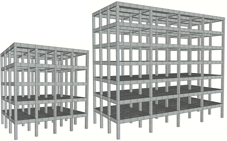
Figure 1. Selected building forms of the 60 and 70s.
Influence of Masonry Infill Walls
In order to examine the influence of the layout of the perimeter frame masonry infill panels to the seismic response of the structure, fully and partially unreinforced masonry frame bays are also considered herein, assumed symmetric in plan in the response direction considered. Out of the different topological possibilities previously considered (Repapis et al., 2006b), three different arrangements of unreinforced masonry infilled frames are studied, denoted as T1–T3, as shown in Figure 2, since they represent the cases most commonly encountered in RC construction:
T1: Perimeter frames fully infilled over the entire height (Figure 2A).
T2: Perimeter frames infilled but with completely open ground storey (called pilotis) (Figure 2B).
T3: Perimeter frames partially infilled, with a vertically continuous window opening (Figure 2C).
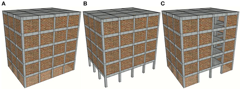
Figure 2. Distribution of masonry infilled walls. (A) T1, (B) T2, (C) T3.
The perimeter infill panels are 25 cm thick irrespective of the building generation, in accordance with the conventional practice of using exterior double leaf infill panels constructed of clay bricks with longitudinal holes and plaster. Single leaf interior partition walls (also denoted as moveable partitions), normally 0.10 m thick, are only included in the mass of the building and are not considered to contribute to the system that resists the earthquake forces.
Design Characteristics
The buildings of the 60 and 70s were designed in accordance with the requirements of the first Greek Earthquake Resistant Design Code which was established in 1959 (RD59, 1959) and was based on the allowable stress design methodology. Loads were unfactored, strict requirements for detailing of the reinforcement were not specified and structural elements of the buildings of that period were characterized by widely spaced transverse reinforcement and, therefore, very little confinement. Moreover, no capacity design provisions were specified. Structural analysis methods for the buildings made use of simplifying assumptions, e.g., the beams and columns of the interior frames were designed for vertical loads and only the members of the exterior frames were designed for frame actions under both seismic and vertical loads, with the corner columns being, in addition, designed for biaxial response of the floor plans due to their mass and stiffness eccentricity.
For the definition of the seismic load a seismicity classification system that adopted three seismic zones was used, with the corresponding base shear coefficients being set equal to 4, 6, and 8% of the vertical loads (namely, dead and live loads without any reduction factors), for buildings on hard ground. The buildings of the 60 and 70s examined in this study were designed for a seismic coefficient of 4%, corresponding to seismicity Zone I. Furthermore, when seismic loading demands were verified in the design process, the allowable stresses specified in the code for vertical loads were increased to 120% of these values, as also considered herein.
Building of the 90s had the same geometry and loads as the building of the 60s (K60A59) and was designed according to EC8 (2004), as the conforming frame benchmark case. This structure was again considered to be located in the same seismicity area as the other two, characterised by an effective peak ground acceleration of 0.16 g (EC8, 2004). The commercial software package Fespa (Logismiki, 2013) capable of designing following the past and current seismic code was used for the design of all the buildings.
The design loads adopted remain the same for all buildings from the 60s through the 90s, and included: the dead loads, namely the structural self-weight and an additional uniformly distributed load equal to 1.50 kN/m2 for floorings and the live load, which is equal to 2.00 kN/m2, similar to the values specified in EC1 (2002). The interior masonry moveable partitions are taken into account as an additional uniform load of 1.00 kN/m2 over the plan. The weight of the 25 cm thick perimeter infills (double wythe construction) was expressed as a uniform dead load of 3.60 kN per square meter of wall façade, imposed on the outer frame beams only.
The 60s building had a uniform slab thickness of 12 cm, beam dimensions of 20 cm by 50 and 35cm square columns at the first (ground) storey, 30 cm square columns at the second storey and 25 cm square columns from the third storey up. Building of the 70s, due to its wider spans, had a uniform slab thickness of 16 cm. Column dimensions were: 60 cm square (interior) and 90/25 cm2 rectangular (exterior), at the first two storeys, being subsequently reduced by 10 cm (interior) and 20 cm (exterior) for every two storeys, respectively, up to the seventh storey, where the columns were 30 cm square (interior) and 35/25 cm2 rectangular (exterior). Similarly, the dimensions of the beams were 20/60 cm2 along the interior frames and 25/50 cm2 along the perimeter frames. Finally, the building of the 90s has similar geometry with the building of the 60s for comparison reasons. Slab thickness is again 12 cm and beam dimensions remain 20 cm by 50 cm, but with increased reinforcement. Column dimensions increase to 40 cm square at the three lower storeys, 35 cm square at the next floor and 30 cm square at the top.
Materials of Construction
The materials of construction for building of the 60s were: (i) DIN B160 concrete having an average (cube) compressive strength of 16 MPa [this material would be classified as C10/12, in accordance with EC2 (2004)]; (ii) smooth mild steel reinforcing bars, grade DIN StI (grade S220). The allowable stress in compression of the concrete, for design under bending with axial load ranged between 6.0 and 8.4 MPa, with higher larger values specified for columns and beams, as opposed to lower allowable stresses for the slabs. Accordingly, the allowable stress in tension of the reinforcement was 140 MPa. For building of the 70s, the materials of construction were: (i) DIN B225 having an average (cube) compressive strength of 22.5 MPa [this would be classified as C12/16 per EC2 (2004)]; and (ii) ribbed high strength steel reinforcing bars, grade DIN StIII (grade S400). For this concrete grade, the allowable stress in compression of the concrete (for bending and axial load designs) ranged between 8.0 and 10.8 MPa (for columns and beams, and slabs, respectively). The allowable stress in tension of the reinforcement was, in this case, 220 MPa. Building of the 90s had materials similar to the one used in building of the 60s for comparison reasons.
Analytical Modelling
Nonlinear static and dynamic analyses were performed using the computer program Drain-2DX by Prakash et al. (1993) for the static and dynamic inelastic analysis of two-dimensional systems. The code was extended with additional finite element modelling capability in order to account for the infills. Furthermore, DrainExplorer (Repapis, 2002), a post-processing program, was developed, for processing the results of all the frame analyses. The selected buildings were regular in-plan and the frames were modelled as plane frames with rigid diaphragms in each floor. The structural mass in all cases was assumed to be lumped at the nodes and was considered, during the time history analysis, to be equal to the inertia mass due to the dead loads plus a portion only of the live load, equal to 30%. For dynamic analysis, mass proportional damping was used, with the damping coefficient determined assuming 5% critical damping in the first fundamental mode response of the cracked structure.
Structural Members Modelling
All the beams and columns of the structures were modelled using a two component concentrated plasticity line element, having bilinear hardening flexural characteristics at the end hinges. Beams were modelled as T-section beams. For the estimation of beam flexural capacities, effective slab widths equal to 1.0 and 0.5 m were assumed for internal and external frame beams respectively, for the buildings with 3.5 m bay length. For the buildings with 6.0 m bay length, these values increased to 1.30 and 0.65 m, respectively. For the estimation of the flexural characteristics of the beams in negative bending, the reinforcement in the effective width of the slab was included.
The nonlinear moment curvature characteristics were developed for all the end critical regions of beams and columns, using average material properties. Furthermore, in the columns, the dependence of these with axial load was considered. According to standard practice of construction at the 60s and 70s, top steel at the critical end sections of the beams included half plus one bent up bars from the two neighbouring midspan sections plus any top additional steel. Moreover, the reinforcement within the slab effective width was also taken into account. The bottom steel at the ends included the remaining unbent midsection bars anchored within the joint.
The average concrete strength was taken to be equal to 16 MPa for concrete grade B160, and 22.5 MPa, for concrete grade B225, respectively. For the reinforcing steel, the mean yield stress was assumed to be 310 MPa and 420 MPa for StI and StIII, respectively, and the average ultimate strength in tension was taken as 430 MPa and 630 MPa, respectively, with these values being measured from tests on smooth steel bars. In all cases, trilinear behaviour for the reinforcement and different constitutive models for the confined concrete core and the cover concrete were considered, in separate section analyses, performed for each member critical region prior to developing the inelastic building models. Beam-column joints were assumed to be rigid.
Infill Walls Modelling
The perimeter infill walls were modelled with equivalent pin-jointed diagonal truss elements (struts) resisting only compressive loads, with out-of-plane effects ignored. An unequal compression–tension truss finite element was used to model the infills, with a trilinear behaviour that is able to model softening with a residual strength. The trilinear envelope comprised of an initial elastic portion, a post-cracking region with positive stiffness and a softening portion, beyond the point of peak axial resistance, with negative stiffness, as shown in Figure 3.
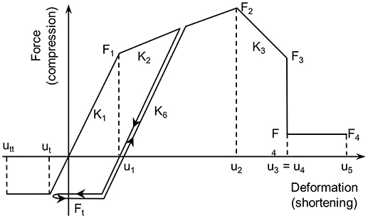
Figure 3. Hysteretic behaviour of infill walls.
The global inelastic characteristics and failure pattern of infilling masonry exhibit large uncertainty and vary significantly with the quality of construction. For the building of the 60s (K60A59) two types of masonry were selected: (i) a strong and stiff good construction quality masonry with a compressive strength f m equal to 2.5 MPa and (ii) a weak and soft poor construction masonry with an infill compressive strength f m equal to 0.5 MPa (buildings denoted as “−05” herein). For the buildings of the 70 and 90s, only good workmanship quality masonry with a compressive strength f m equal to 2.5 MPa was selected. The thickness of the equivalent diagonal struts is the same as the thickness of the infill panel. Mainstone's approach was used to determine both the initial stiffness Kin = K1 in Figure 3 and the effective width Wef of the diagonal strut (Mainstone, 1971):
with,
where Ew and Ec are the uncracked secant moduli of elasticity of the infill wall and the RC frame members, respectively, θ = arctan(Hw/Lw) is the diagonal strut's inclination, tw is the thickness of the infill wall, Ic is the moment of inertia of the frame columns, whereas Hw and H are the height of the infill wall (clear from slab to beam soffit) and the storey height, respectively, while Lw and L are the clear length of the infill from column to column and the bay width, respectively. Following a proposal by Paulay and Priestley (1992) it was assumed that Ew = 750 f m for clay bricks. The initial lateral stiffness K1, according to Mainstone (1971), is equal to
The simplified expression by Žarnić and Gostić (1997) as given bellow, extended from an initial suggestion by Dolšek and Fajfar (2002), was used for the evaluation of the peak resistance of the infills Fmax in Figure 3. Fmax was assumed to occur at an axial deformation of the strut u2 equal to 0.5% of the storey height H:
and
where f tp is the cracking strength of the infill, obtained from a diagonal compression test, and θ, Lw and Hw as previously defined. Compressive cracking forces were assumed to be equal to approximately half of the corresponding ultimate resistance, F1 = Fmax/2, following (Dolšek and Fajfar, 2002), while the tensile strength of the infill (Ft, Figure 3) was assumed to be zero. The stiffness of the softening branch was taken as 10% of the initial stiffness K1 while the residual strength F4 was set equal to 15% of Fmax, primarily for numerical stability.
In the results reported herein, two different levels of infill resistance Fmax are considered only for building K60A59. For all the other case study buildings, infilled frames with relatively good quality masonry were considered only, representative of the construction pattern, the quality of the materials and the workmanship of that period.
Seismic Assessment Using IDA Procedures
The seismic assessment of the non-conforming infilled RC buildings considered herein has been previously investigated using an SPO procedure analysis methodology described in Repapis et al. (2006a). The results of an extensive study for the seismic assessment of a wide range of regular and irregular, bare and infilled, existing RC buildings of the 60 till the 90s, using SPO, were presented in Repapis et al. (2006b). Inelastic SPO analyses were performed with both uniform and inverted triangular load profiles. Both global and local limiting performance criteria (LC) were considered (Repapis et al., 2006a,b) for performance assessment and nominal failure of the building was defined at the minimum deformation over all monitored criteria. From these analyses, the overstrength, the global ductility capacity and behaviour factor were evaluated and the failure mechanism and the critical LC were identified. Moreover, upon determination of the buildings' capacity curve, their target displacement demand was determined in accordance with the N2 methodology by Fajfar (1999) which is adopted by EC8-3 (2005), and was compared with the peak lateral deformation of the building.
In the present study, the seismic performance obtained using the IDA procedure is compared with the performance obtained from SPO procedures above, considering similar LC. For this purpose, 14 recorded base accelerograms were selected and used and, inelastic time history analyses were executed for each base excitation record and for increasing values of the recorded peak ground acceleration (PGA), until yield was exceeded and any failure LC considered was imminently reached, signifying nominal collapse. For each time history analysis, the maximum base shear and the corresponding spectral acceleration or PGA (the Intensity) are plotted against the maximum displacement or interstorey drift (the damage index), in order to establish the IDA curve for global response. Moreover, for meaningful comparison with the vulnerability predictions obtained with SPO analysis at the target point for these buildings, the time history response is also computed under all base excitations also being scaled to the design response spectral intensity, currently in effect for each building under the currently enforced regulations (EC8, 2004). For selected base inputs (e.g., record KAL18601Long), the as recorded unscaled PGA intensity is also considered, since it was close to this design level intensity.
The quantification of the structural performance of the buildings is made at both global and local levels. Some response parameters of interest are the minimum elastic response spectrum acceleration intensity inducing first yield in any structural member, , the minimum elastic response spectrum acceleration intensity inducing conventional collapse, and the corresponding maximum absolute values of the roof deformation δy and δu, respectively. The evolution of peak local damage and demand indices, with record intensity, is also monitored.
The available behaviour factor q and global ductility capacity μ for the buildings are evaluated using IDA, in a similar approach as in SPO, assuming that the spectral amplification remains constant with increasing intensity. The behaviour factor q is established as the ratio of the PGAs of the collapse and onset of yield earthquakes (Salvitti and Elnashai, 1996), while global ductility capacity μ as the ratio of the corresponding roof drifts, as depicted in the following Equation 6:
The LC at both the local and global levels, which were adopted in SPO analyses, for the estimation of conventional collapse, as described in detail in Repapis et al. (2006a), are also adopted herein for the IDA study. Consequently, during each inelastic time history analysis, the following checks were performed during step by step time history analysis:
i) Exceedance of the plastic rotation capacity of the columns at the critical regions, equal to the section's ultimate curvature under the axial load of the member (for columns) at the current time step, times the plastic hinge length (LC designated as θpl). The length of the plastic hinge was taken equal to (a) half the section effective depth or, (b) following a more refined empirical expression proposed by Paulay and Priestley (1992), whichever governed,
ii) exceedance of the member shear strength capacity under current axial load (LC designated as V), according to current design Code,
iii) local capacity of the masonry infill panels, assumed to be exceeded when the axial load of the equivalent diagonal struts representing the infill reaches its maximum strength (LC designated as Infill) and
iv) exceedance of the maximum interstorey drift (LC designated as dr). A limit of 1.25% was assumed for buildings of the 60 and 70s, designed for past generation of codes and 2.5% for buildings of the 90s designed according to modern codes.
Beam-column joint shear capacity was only checked in SPO analysis. It was shown that this limit criterion was not critical because other failure modes preceded.
For the automatic performance of the required time history analysis, for increasing peak ground acceleration intensity and for the evaluation of all LC in a step by step manner, the computer code DrainExplorer (Repapis, 2002) was used. The analysis input parameters are the geometry of the building and the structural materials, reinforcement detailing of all critical regions of the members, base input excitation record and its elastic response spectrum characteristics. The critical region cross-section characteristics are calculated for all members. The ground motion record is scaled automatically and Drain-2DX (Prakash et al., 1993) is called by DrainExplorer to perform the corresponding time history analysis. For each dynamic analysis at a given PGA, DrainExplorer post processes the results to check all LC at every step of the analysis, in order to identify the critical excitation for all LC. Moreover, the plastic hinge distribution, the deformed shape, the vertical interstorey drift distribution, the energy absorption among the beams, columns, and infills with height, the current state of each member, the local plastic rotations and ductility demands, the capacity check of the joints and the shear capacity ratios for each member are some of the parameters monitored in every step of the analysis and for each base input intensity.
The procedure is repeated for another scale of the ground motion, until all LC are exceeded and yield and conventional failure are identified. The upper bound of the intensity of the base excitation is reached when the predefined limiting roof displacement is exceeded. Next, additional time history analyses are performed in an iterative manner for scaled values of the PGA around the values of yield and collapse PGA, in order to evaluate with increased accuracy and and, therefore, the available behaviour factor q and the ductility capacity μ of the building. Finally, the entire IDA curve is traced.
Nonlinear Analyses Results
The inelastic analysis results following IDA for the full set of infilled plane frames, including, for comparison, their bare frame counterparts, using the set of base excitations in Table 2, are presented and discussed herein. For comparison, SPO analyses, previously reported on these frames (Repapis et al., 2006b), are also briefly described. The purpose of the analyses is 2-fold, namely: (i) on one hand, to investigate the seismic performance of these infilled frames, and, (ii) on the other hand, to establish the reliability of performance prediction of SPO methods to assess these structures' seismic performance under actual recorded excitations, compatible with the design assumptions currently enforced.
The graphic results of the inelastic analyses are given in Figure 4 for the SPO studies and in Figures 7–12 for the IDAs. All SPO derived key performance indices are also given in tabular form in Table 1 and include, for each structural case study: (a) the assumed compressive strength of the masonry infill walls fm strength (for the infilled frames), (b) the plane frame fundamental period T1, obtained from modal analysis (not the effective stiffness), (c) the maximum base shear Vmax, the corresponding overstrength Ω and the supplied behaviour factor of the building q of the equivalent bilinearized single degree of freedom (SDOF) system following the methodology proposed in Repapis et al. (2006a). Furthermore, in terms of the kinematic parameters, are given: (i) the analytically obtained peak global roof drift prediction at failure, δu, (ii) the target point demand δt, determined according to the N2 methodology by Fajfar (1999), and (iii) the corresponding ductility supply μ of the SDOF system. Finally, the controlling LC on which δu was established is also reported, in order to separate brittle from ductile nominal failure forms in the response.
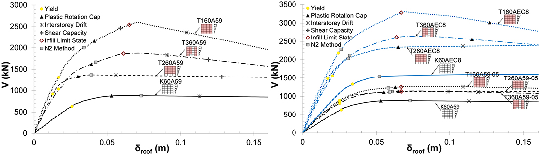
Figure 4. Inelastic pushover (SPO) characteristics of bare and infilled frame structures K60A59 and K60AEC8.
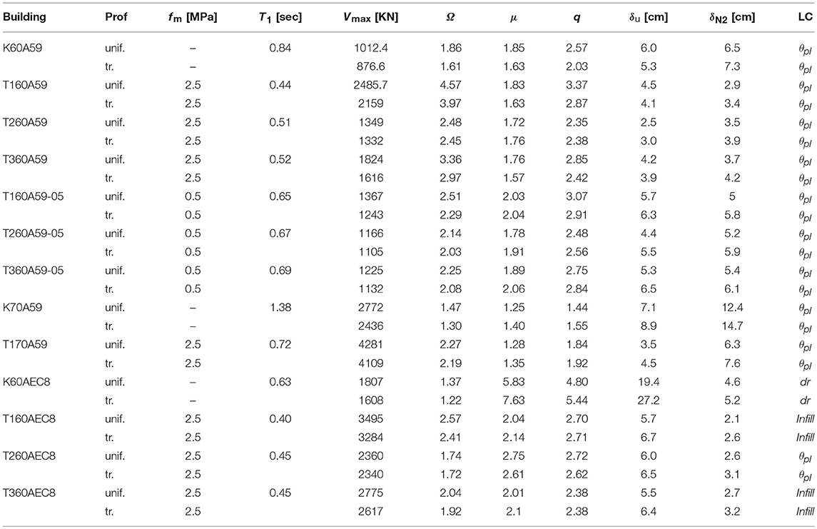
Table 1. SPO analyses results for uniform and triangular distribution of lateral loads.
Response Prediction Based on SPO Analyses
Prior to examining the IDA response, the SPO predictions are briefly initially examined, while, further on, the reliability of SPO to safeguard against actual earthquake response is considered by comparing SPO with IDA results. The capacity curves following inelastic plane frame SPO analyses under a triangular distribution of the lateral loads are given in Figure 4 for the bare and infilled frame configurations, for all frames considered. In all cases, the first initiation of yield δy, the target point prediction using the N2 method (Fajfar, 1999) and the roof deformation levels for the different LCs are also depicted, with the minimum of which establishing the roof deformation at nominal failure δu for each frame (see also Table 1). Pushover curves for the bare and infilled frame of the 70s is out of scale and is not shown in Figure 4, however, they can be found in Repapis et al. (2006b) and Zeris and Repapis (2018). The results are tabulated in Table 1 for both uniform and triangular distribution of the lateral loads. For a more detailed discussion of the use of these curves for the evaluation of the design level at allowable stress and ultimate, the overstrength and the supplied behaviour factor of each building, (see Repapis et al., 2006a,b).
Considering the SPO capacity curves it is observed that the governing LC for all bare and infilled frames is the exceedance of the plastic rotation capacity in the critical regions (θpl), with the exception of the conforming fully and partially infilled buildings T160AEC8 and T360EC8, for which infill failure is the critical LC, and for the conforming bare frame K60AEC8, for which interstorey drift limit of 2.5% is critically exceeded first, prior to all other LCs. Apart from these three buildings, infill or shear failure and interstorey drift always occur at roof deformations higher than the onset of the plastic rotation capacity LC. The inclusion of the infills results in a considerable increase in the initial stiffness, while also, the maximum displacement at failure of the infilled structures is decreased compared to the bare frames. Due to the interaction between the RC frame and the infills the shear strength of columns is surpassed earlier than the bare frame structures, with this LC, however, not being critical, since it follows the aforementioned LC of θpl. Regarding the performance of the structure, it is observed that the target point demand following the N2 method exceeds nominal failure in all non conforming frame cases, with the exception of the fully or partially infilled frames, be it with a good or a low quality infill material, whose nominal failure takes place after the target demand. Expectedly, the conforming EC8 designs are by far performing the best whether infilled or bare, and have ample reserves of deformation beyond the target demand.
Response Prediction Based on IDA
The seismic performance predictions using SPO analyses, above, are compared to the results of inelastic dynamic analyses using the IDA methodology of Vamvatsikos and Cornell (2004). To this purpose, the subject buildings were analysed in the time domain using 14 actually recorded time history base excitations, recorded during recent earthquakes in Greece and abroad. The time history traces (as recorded) for these excitations are depicted in Figure 5. In Figure 6, the linear elastic acceleration response spectra of the record set for 5% damping, are compared to the smoothed Elastic Design Response Spectrum (EDRS) prescribed in EC8 (2004) for seismicity zone I (PGA equal to 0.16 g, in the Greek National Annex of EC8), to which these building designs correspond in currently enforced seismic regulations. In the same plot are also depicted the linear elastic first mode periods of the subject buildings (denoted T1, in Table 1).
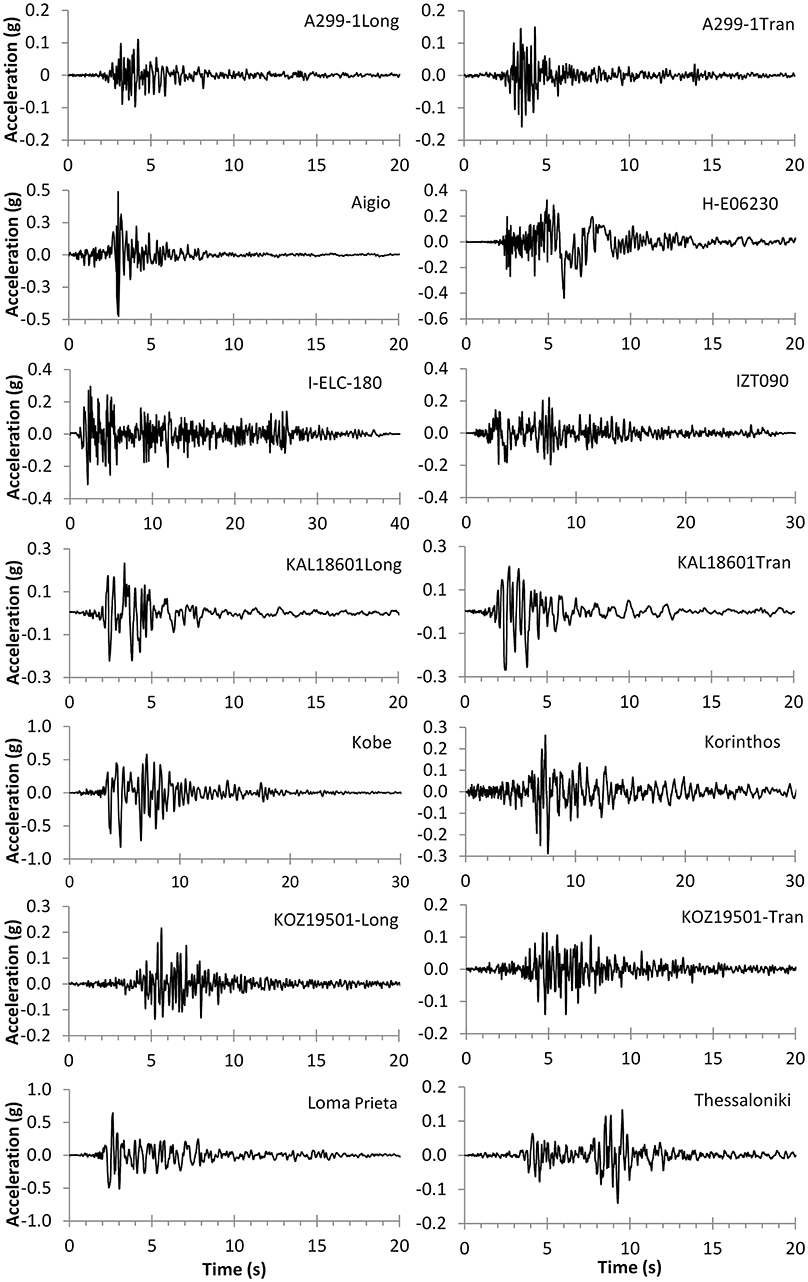
Figure 5. Earthquake record time histories used in IDA analysis.
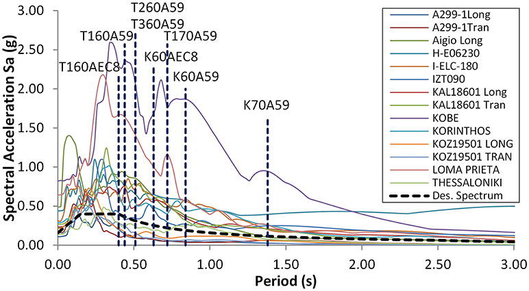
Figure 6. Elastic response spectra of the as recorded accelerograms and predominant periods of the case study buildings.
For each recorded excitation, the base time history is obtained for subsequent scaling in IDA, compatible with the design seismic intensity currently enforced in the seismicity zone in which each structure is located; this scaled record excitation is obtained from the actual recording scaled so as to match the Velocity Spectrum Intensity (VSI) of the zone I EDRS of EC8 (2004). The as recorded record characteristics, namely: (i) PGA, (ii) the peak ground velocity (PGV), (iii) the record duration td, defined as the time elapsed between the times at the 3 and 97% limits of the Arias Intensity, (iv) the Arias Intensity (AI), and (v) the parameter VSI are also given in Table 2, for comparison of the characteristics of the base excitation time history set.
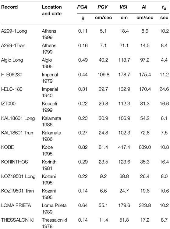
Table 2. Ground motion characteristics of the fourteen acceleration records used in IDA.
Dynamic Response Variability and Global Damage Prediction
For each building and record considered, a typical IDA series involved about 20 time history analyses, leading to a total of more than 4,500 nonlinear dynamic analyses, for the entire building and record set. The results of all records' IDA analyses for all buildings are initially compared in Figure 7, in terms of the structures' global response under each nonlinear time history analysis, namely peak absolute interstorey drift vs. the corresponding spectral acceleration. For statistical evaluation purposes, in addition to the entire set of IDA curves the median IDA of all 14 records together with the 16 and 84% fractile plots are also depicted, together with the corresponding global LC (previously designated dr), namely 1.25% for non conforming frames and 2.5 % for conforming frames (off graph scale); one should stress, however, that the actual controlling LC for nominal failure, in each IDA analysis, differed for each structure and record case, with the majority of cases governed by structural LCs and followed by infill failure at higher intensities, as presented in more detail later on.
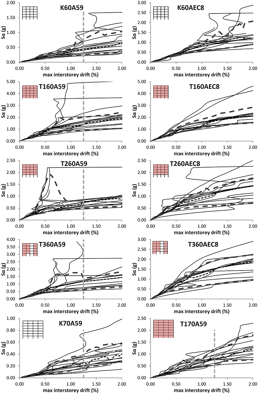
Figure 7. IDA curves for the bare and infill frames considered: median, 16 and 84% fractiles for all 14 records considered.
The inclusion of infills over the entire height of the building results in a considerable increase in the structure's lateral overstrength, in the case of the non conforming buildings as this is manifested by comparing the spectral intensities to reach a given storey drift, for the bare (and pilotis) frames and their infilled counterparts for all building generations: while the bare frames attain the critical drift limit of 1.25% at about 0.70 and 0.36 g (K60A59 and K70A59 frames, respectively), the corresponding fully and partially infilled frames attain this value at 2.00 g (T160A59), 0.85 g (T260A59), 1.4 g (T360A59), and 1.15 g (T170A59) respectively, namely 285, 121, 199, and 319% of the bare frame counterpart, with the corresponding ratios of peak resistance under SPO being 246, 152, 184, and 169%, respectively, for these buildings (Repapis et al., 2006b). It is therefore concluded that IDA predictions with drift limit criteria considerations generally predict higher overstrengths than SPO, except the irregularly infilled frame with the open ground storey (T2), whose performance is overly optimistic under static inelastic analysis, with the pilotis having the worst prediction errors. Fully infilled frame of the 70s has the worst prediction errors. The opposite is observed to the conforming frames, for which the IDA predictions with drift limit criteria considerations generally predict lower overstrengths than SPO.
Comparing the IDA response in Figure 7 among the bare and infilled frames and concentrating in particular to the 84% fractile and median peak storey drifts for given spectral intensity, it is seen that the presence of the infills results in an overall reduction of the scatter between the two, compared to the bare frames; the latter structural forms (both 60 and 70s) invariably exhibit higher deviations between the two IDA curves, with increasing base input intensity–with building K70A59 being the worst in performance at relatively lower intensities. The entirely opposite holds true for the pilotis cases (the T260A59 and T260AEC8 designs offscale), for which the difference between the latter two curves is minimal at the LC dr level, with building T260A59 exhibiting an initially relatively stronger resistance for small storey drifts, quickly dropping, however, to the bare frame spectral acceleration levels at higher drifts, due to the soft storey: this expected response transition is actually corrected for by infilling two bays at the open ground storey (the T360A59 and T360AEC8 designs), following closer the spectral acceleration levels of the fully infilled cases; it should be mentioned at this point that infill configuration T360XX, with two infilled bays at ground storey, is being used in Greece as a possible seismic intervention scheme of existing pilotis RC buildings.
It is interesting to note further, that for each building type there exist up to four records (~30% of the sample) for which the IDA demands increase disproportionately compared to the remaining records in the set, and dynamic instability is obtained at storey drifts over 0.5, 1.2, and 1.0% drifts for pilotis, bare and infilled frames, respectively; these records vary with building type and are consistently within the subset of A299-1, Aigio, KOZ19501, and THESSALONIKI (Figure 7).
Quantification of the Seismic Performance Indices
Further to the overall comparison of the IDA and SPO results based on the LC dr only, and given that, as subsequently discussed, the form of failure is not the same among different records and structural forms (in fact the nominal failure controlling LC varies even between IDA and the SPO prediction), the actual seismic performance predictions are subsequently considered in more detail. To that effect, the basic performance parameters used for the equivalent SDOF (re)design of RC structures, namely the provided behaviour (q) factor and ductility capacity, and the corresponding global damage index as expressed in terms of the roof displacement at failure, are compared between the SPO and IDA in Figure 8, with the corresponding values (and their statistics) given in Table 3 for all the buildings and record analyses at hand. An immediate comparison between the conforming (K60AEC8) and non conforming bare frames of the 60 and 70s reveals the influence of the conforming detailing and current seismic design requirements in a resulting considerable increase in all their performance indices: compared to the bare frame (K60A59) which exhibits a median behaviour factor and global ductility of 2.4 and 2.2, the corresponding values for conforming building K60AEC8 are 8.6 and 7.5, respectively. The inclusion of the infills, however, in these frames, has the opposite effect in their seismic performance indices. Considering the corresponding median behaviour factor and global ductility values it is observed that these remain or increase to 2.7 and 2.4 (T160A59), 2.5 and 2.0 (T260A59, pilotis), 2.4 and 2.2 (T360A59, upgraded pilotis)–with even better performance of the weak infill wall pilotis (T260A59-05), while they are reduced to 3.9 and 3.0 for the fully infilled conforming frame (T160AEC8). This observation does not apply to the 70s group, which are relatively taller and have larger spans, for which the poor bare frame performance (median q and μ equal to 1.9 and 1.8, frame K70A59) compares to even lower values of median q and μ equal to 1.2 and 1.2 for the fully infilled frame T170A59. Equally importantly, the scatter in the IDA results (see, e.g., the standard deviation and coefficients of variation in Table 3) for fully infilled structures is reduced to half of the bare frame for T160A59 and T160AEC8, while it increases for the corresponding 70s frames. Similar observations hold true also for the peak global roof deformations.
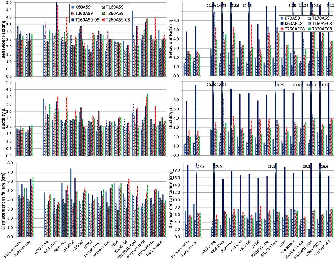
Figure 8. Behaviour factor q, ductility μ and top displacement at failure evaluated from SPO and IDA analyses. (Note that building K60AEC8 results are out of scale).
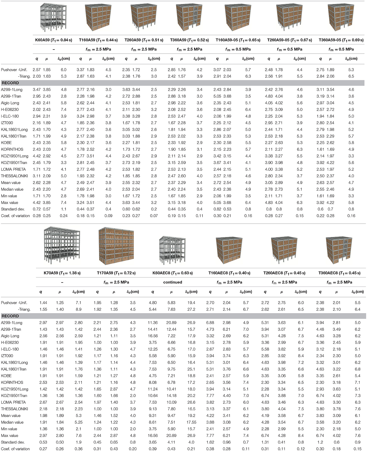
Table 3. Behaviour factor, ductility and minimum roof drift at failure, evaluated from SPO, and IDA analyses for all the records considered, together with the mean, median, minimum, and maximum values of the entire IDA analysis set, for each building (for each frame, the predominant period, and infill strength are also noted).
Compared to the SPO predictions, one again observes that median IDA values are nearly equal (K60A59) or higher (K70A59, K60AEC8) than the SPO predictions (uniform distribution), which are therefore more conservative for use in redesign, yet, in this case, IDA predictions systematically are lower than the SPO predictions in the supplied behaviour factor of the non conforming frames (T160A59 and T170A59), implying that assessment and verification methods adopting the SPO values not to be conservative in the frame performance levels; again, unlike T160A59, for the 70s infilled frame the ductility marginal difference between IDA and SPO vanishes.
Local Resisting Mechanisms and Energy Absorption
This overall difference in performance of the bare and infilled frames can be qualitatively related to the distribution of resting mechanisms and their failure extent, considering in Figure 9 the time history snapshot at the end of the analysis for the unscaled KAL18601Long record. At this instant the hinge distributions and their relative demands, the extent of cracking in the infills and the energy absorption for all the infill configurations of frame K60A59 (internal and external) are plotted. In this Figure comparisons of (i) the plastic hinge distributions between the members and the flexural ductility demands in the hinge, (ii) the possible onset of failure in the corresponding hinge, (iii) the extent of cracking in the infill struts, and (iv) the energy absorption per storey, of the beams, the columns and the infill struts, relative to the total energy absorbed, are shown. It is seen that, while the bare frame attains the maximum drift through a soft storey mechanism in the third and fourth storey and failure of the columns, with very little energy contribution from the beams, including a regular infill pattern results in the lower four storeys contributing in the energy absorption with a complete correction of the soft storey formation. Furthermore, the change in the response profile results in this case in a failure at this instant of the base column heads only, while the beams are in this case mobilized fully with higher ductility demands and no failure. The pilotis configuration follows the bare frame performance, with the exception that the soft storey formation is in this case forced to the ground storey, causing the columns to fail in this location. Again, this type of response is corrected by partially infilling two ground storey bays at the ends of the exterior frame only (case T360A59).
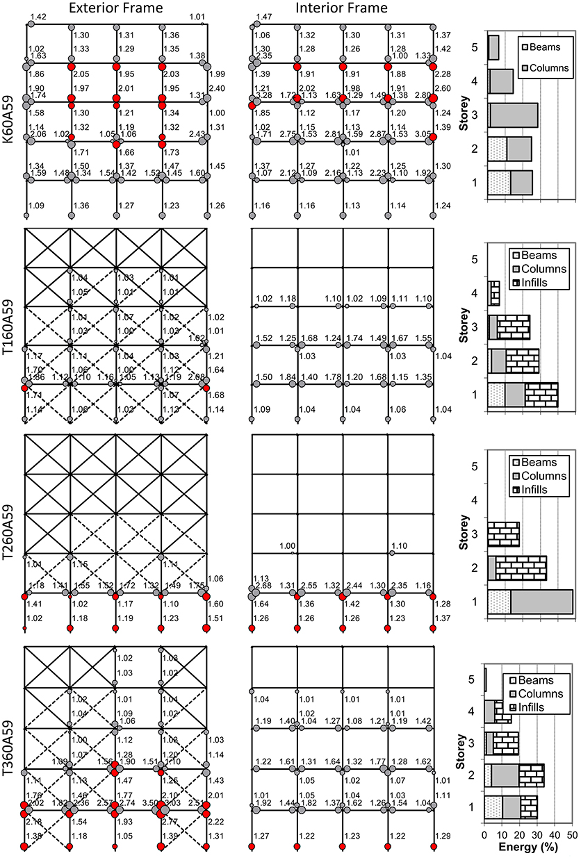
Figure 9. Plastic hinge distribution, ductility rotation demands and energy absorption at the end of the analysis. KAL18601Long record (unscaled). Red plastic hinges have failed. Infills are plotted in “dashed” line if cracked.
The peak roof deformation demands at first onset of yield and at nominal failure, is compared with the peak deformation of the as recorded and scaled record inputs for all 14 records and for each building, in Figure 10; furthermore, the entire demand history with increasing base input is demonstrated for these buildings considering the median IDA response in terms of roof deformation and interstorey drift in Figure 11. In the case of the 60s frame configurations characterised by a smaller number of floors and relatively dense column spacing, the first yield deformation does not differ among the different types of structural systems (bare frames and infilled configurations with good or weak infill masonry quality). This is not the case for K70A59 and T170A59 for which the onset of yield varies with the input content, albeit in the same manner for both building forms. Considering the deformation at failure vis-a-vis the peak deformation demand of the scaled input, one observes that: (i) both the drift and the roof deformation at first yield are fairly insensitive to the infill configuration or lack thereof, lying in the 0.2% range, (ii) in absolute value, roof or storey deformations at failure of the bare frames are lower than the corresponding deformation of the scaled earthquake record, (iii) inclusion of the infills for building K60A59 (but not K70A59) results in correcting for this deficiency in the infilled frames, with the exception of the KAL18601Long, KOZ19501TRAN and Loma Prieta records; and (iv) the infill configuration affects favourably and very strongly the safety margin between scaled input response and failure of the conforming frames, which have the most favourable response.
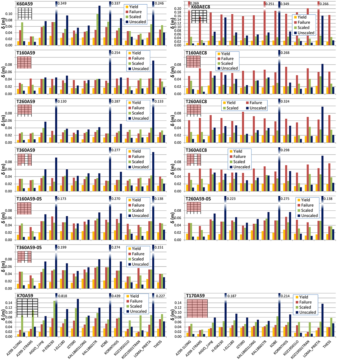
Figure 10. Roof displacements from IDA analysis for the 14 records. Values for yield, failure, the scaled record to the design spectrum and the unscaled (raw) record are shown.

Figure 11. Comparison of the median IDA intensity curves for the bare and infill frames considered in terms of the dr global LC.
Form of Nominal Failure and Target Point Prediction
Since the actual form of failure (the controlling LC) varies with record and building type, the median IDA results of the peak base shear and peak roof deformation are compared with the SPO predictions for all the 60s frames (bare, infilled, pilotis, weakly infilled) in Figure 12, with designation, in each case, of the controlling LC. From the load resistance curve comparisons it is demonstrated clearly that the overstrength under IDA is consistently higher than SPO estimation under the triangular lateral force distribution (and closer, for K60A59 to the uniform load distribution, see Repapis et al., 2006b); the scaled input median IDA deformation demand is consistently less than nominal failure for the infilled frames (T160A59), marginally so for the partially or weakly infilled frames (T360A59 and both T160A59-05 and T360A59-05) and exceeds the deformation capacity for the bare frame and the pilotis. This difference in overstrength also results in a consistent increase of the target point prediction based on the N2 method (Fajfar, 1999) under SPO, relative to the median IDA prediction under the scaled record inputs. It should be noted, also, that the LC controlling this nominal failure differs in each case and in no case (SPO or IDA) is the infill controlling failure: in most cases flexural plastic rotations are exceeded in columns, albeit at different axial loads for the bare and infilled frames, due to the change in the structural system. This is not the case for the conforming frames. The critical LC for the conforming bare frame (K60AEC8) is the interstorey drift, while for the fully infilled (T160AEC8) and the partially infilled (T360AEC8) frames, the critical LC in most cases (SPO and IDA) is exceedance of the infill capacity. However, for the open ground storey (T260AEC8) frame, energy absorption concentrates at the open storey and critical LC is, in most cases, the failure of the ground columns.
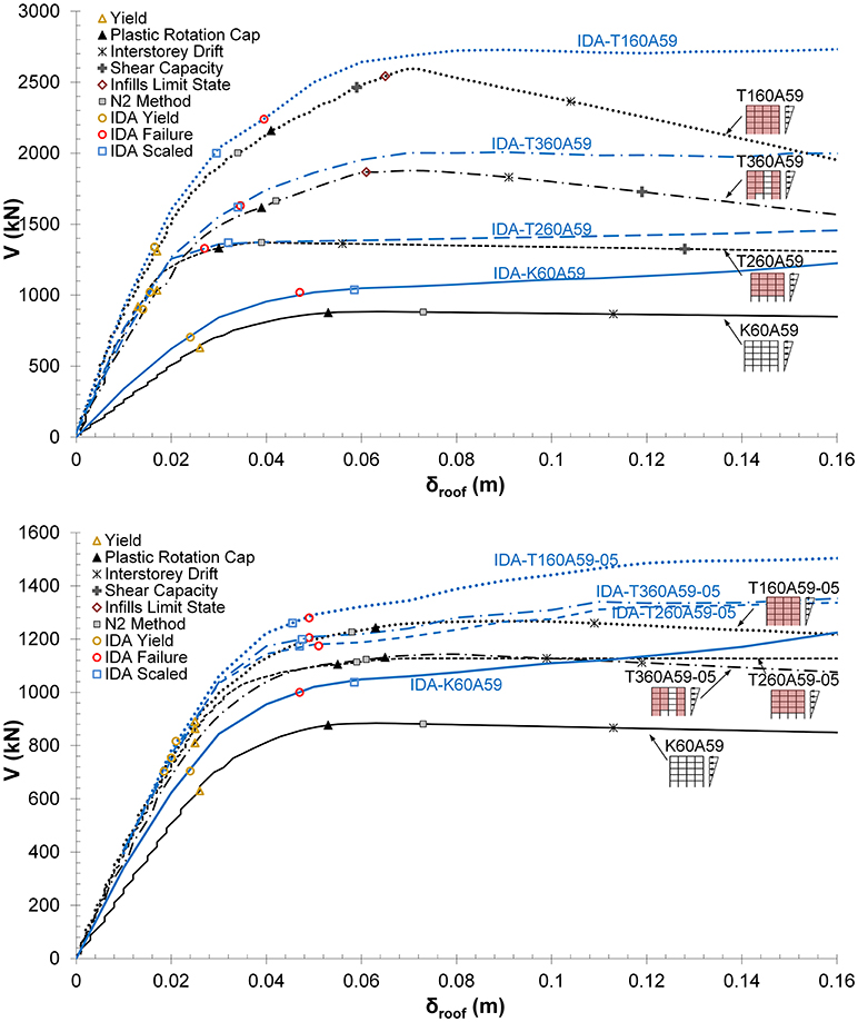
Figure 12. SPO and median IDA predictions for the bare (K60A59) and infill (T160A59, T260A59 and T360A59) frames of the 60 s.
Conclusions
The present study aims at the vulnerability assessment of non-conforming infilled RC structures of the 60 and 70s, which represent a significant portion of the whole building estate in Greece and other seismically affected countries worldwide. The seismic performance of typical bare and infilled structures was evaluated using nonlinear pushover and time history analyses. The results from Incremental Dynamic Analysis were compared with previous analysis assessments on the same structures, based on static inelastic prediction procedures. Based on the findings of this study, the following can be concluded regarding the expected inelastic performance of typical non-conforming infilled RC buildings under seismic excitation:
• The inclusion of infills regularly distributed over the entire height of the building resulted in a considerable increase in the structure's lateral overstrength compared to the bare frame, followed by a companion reduction in their deformability. Furthermore, observed scatter of the IDA results was reduced compared to the bare frames.
• IDA overstrength predictions were higher, compared to the SPO predictions for the non conforming frames, with the opposite being observed for the conforming case. Accordingly, SPO methods overestimated the target displacement, as compared to the median value obtained using IDA. Moreover, deformation capacity was also overestimated by the SPO methods.
• The form and criterion governing failure differed among different records and structural forms. In the bare frame of the 60s a soft storey mechanism occurred between the third and fourth storeys due to the reduced dimensions of the columns, while the fully infilled frame suffered extensive damage at the lower storey infills, resulting to a soft storey at the lower two storeys. In general fully infilled frames presented a better distribution of damage along the height of the structure. Infilled frames with an open storey concentrated all the inelastic action at the base and exhibited the worst performance; introducing a few infill bays at the soft storey level provided these buildings with increased resistance, similar to the infilled frames. The plastic hinge rotation capacity of columns was the governing LC for all non-conforming bare and infilled frames. On the contrary, the critical LC was the interstorey drift for the conforming bare frame, while the capacity of the infills governed for the fully or partially infilled frames.
• IDA predictions of the basic performance parameters, such as the available behaviour factor, ductility capacity and deformation at failure exhibited high scatter, with SPO predictions being within the range of the IDA predictions. One important point regarding the building generation and form is that overall, infilled buildings of the 60s exhibited a higher ductility capacity and behaviour factor under IDA (q and μ equal to 2.4 and 2.2 for the bare frame, and 2.7 and 2.4 for the fully infilled frame, respectively) than SPO predictions, due to their relatively dense column spacing. The opposite holds true for the 70s buildings, with wider spans and more storeys, which, under SPO, had relatively worse performance than the 60s; under IDA, their median performance indices were even lower (q and μ equal to 1.9 and 1.8 for the bare frame, and 1.2 for both q and μ for the fully infilled frame, respectively) than the SPO values.
• For non-conforming bare frames of the 60 and 70s, maximum deformation capacity is smaller than the demand under the scaled record inputs. On the contrary, for fully infilled frames the deformation demand is less than nominal failure and marginally so for the partially or weakly infilled frames (T360A59 and both T160A59-05 and T360A59-05). The open ground storey (pilotis) frame (T260A59) has the worst performance, for which demand exceeds the deformation.
In view of the complexity and number of parameters involved in the evaluation of the seismic vulnerability of existing RC frame structures (both infilled and not), the findings of the present study can further be refined by considering the following modelling improvements, currently under investigation: (i) three-dimensional response effects, under different plan infill configurations, (ii) additional LCs involving, among others, the lack of proper anchorage and the buckling of the compression reinforcement, (iii) improved modelling techniques to account for modelling of the joint behaviour and the pinched cyclic characteristics of the members; and (iv) uncertainty in the quality of the materials.
Author Contributions
CR formulated the problem, carried out the literature review, developed the numerical models, conducted the computation, drew the figures and wrote the paper. CZ formulated the problem, carried out the literature review, developed the numerical models, conducted the computation, drew the figures and wrote the paper.
Conflict of Interest Statement
The authors declare that the research was conducted in the absence of any commercial or financial relationships that could be construed as a potential conflict of interest.
References
Anić, F., Penava, D., and Sarhosis, V. (2017). “Development of a three-dimensional computational model for the in-plane and out-of-plane analysis of masonry-infilled reinforced concrete frames,” in COMPDYN 2017 6th ECCOMAS Thematic Conference on Computational Methods in Structural Dynamics and Earthquake Engineering (Rhodes Island).
Asteris, P. G., Antoniou, S. T., Sophianopoulos, D. S., and Chrysostomou, C. Z. (2011), Mathematical macromodeling of infilled frames: state of the art. J. Struct. Eng. ASCE 137, 1508–1517. doi: 10.1061/(ASCE)ST.1943-541X.0000384
Asteris, P. G., and Cotsovos, D. M. (2012). Numerical investigation of the effect of infill walls on the structural response of RC frames. Open Constr. Build Tech. J. 6, 164–181. doi: 10.2174/1874836801206010164
Asteris, P. G., Cotsovos, D. M., Chrysostomou, C. Z., Mohebkhah, A., and Al-Chaar, G. K. (2013). Mathematical micromodeling of infilled frames: state of the art. Eng. Struc. 56, 1905–1921. doi: 10.1016/j.engstruct.2013.08.010
Asteris, P. G., Repapis, C., Repapi, E., and Cavaleri, L. (2017). Fundamental period of infilled reinforced concrete frame structures, structure and infrastructure. Engineering 13, 929–941. doi: 10.1080/15732479.2016.1227341
Asteris, P. G., Repapis, C., Tsaris, A. K., Di Trapani, F., and Cavaleri, L. (2015). Parameters affecting the fundamental period of infilled RC frame structures. Earthquakes Struc. 9, 999–1028. doi: 10.12989/eas.2015.9.5.999
Attard, M. M., Nappi, A., and Tin-Loi, F. (2007). Modeling fracture in masonry. J. Struc. Eng. 133, 1385–1392. doi: 10.1061/(ASCE)0733-9445(2007)133:10(1385)
Bakas, N. P., Babouskos, N. G., Kokkinos, F. T., and Katsikadelis, J. T. (2009). “Influence of infill walls in the dynamic response of buildings via a B.E. Modeling,” in Proceedings of the 10th International Conference on Advances in Boundary Element Techniques (Athens).
Basha, S. H., and Kaushik, H. B. (2012). “Evaluation of shear demand on columns of masonry infilled reinforced concrete frames,” in Proceedings of the 15th World Conference on Earthquake Engineering (Lisbon).
Bolea, O. (2016). The seismic behaviour of reinforced concrete frame structures with infill masonry in the Bucharest area. Energy Procedia 85, 60–76. doi: 10.1016/j.egypro.2015.12.275
Borzi, B., Crowley, H., and Pinho, R. (2008). “The influence of infill panels on vulnerability curves for RC buildings,” in Proceedings of the 14th World Conference on Earthquake Engineering (Beijing).
Buonopane, S. G., and White, R. N. (1999). Pseudodynamic testing of masonry infilled reinforced concrete frame. J. Struc. Eng. ASCE 125, 578–589. doi: 10.1061/(ASCE)0733-9445(1999)125:6(578)
Burton, H., and Deierlein, G. (2014). Simulation of seismic collapse in nonductile reinforced concrete frame buildings with masonry infills. J. Struc. Eng. 140:A4014016. doi: 10.1061/(ASCE)ST.1943-541X.0000921
Cavaleri, L., and Di Trapani, F. (2014). Cyclic response of masonry infilled RC frames: experimental results and simplified modeling. Soil Dynam. Earthquake Eng. 65, 224–242. doi: 10.1016/j.soildyn.2014.06.016
Cavaleri, L., Fossetti, M., and Papia, M. (2005). Infilled frames: developments in the evaluation of cyclic behaviour under lateral loads. Struc. Eng. Mechan. 21, 469–494. doi: 10.12989/sem.2005.21.4.469
Chiou, T. C., and Hwang, S. J. (2015). Tests on cyclic behavior of reinforced concrete frames with brick infill. Earthquake Eng. Struc. Dynam. 44, 1939–1958. doi: 10.1002/eqe.2564
Chiozzi, A., and Miranda, E. (2017). Fragility functions for masonry infill walls with in-plane loading. Earthquake Eng. Struc. Dynam. 46, 2831–2850. doi: 10.1002/eqe.2934
Choudhury, T., and Kaushik, H. B. (2018). Seismic response sensitivity to uncertain variables in RC frames with infill walls. J. Struc. Eng. 144:04018184. doi: 10.1061/(ASCE)ST.1943-541X.0002190
Chrysostomou, C. Z., and Asteris, P. G. (2012). On the in-plane properties and capacities of infilled frames. Eng. Struc. 41, 385–402. doi: 10.1016/j.engstruct.2012.03.057
Chrysostomou, C. Z., Gergely, P., and Abel, J. F. (2002). A six-strut model for nonlinear dynamic analysis of steel infilled frames. Int. J. Struc. Stability Dynam. 2, 335–353. doi: 10.1142/S0219455402000567
Crisafulli, F. J. (1997). Seismic Behaviour of Reinforced Concrete Structures With Masonry Infills. Ph.D. Dissertation, University of Canterbury, New Zealand.
Dhanasekar, M., and Page, A. W. (1986). “Influence of brick masonry infill properties on the behaviour of infilled frames,” Proceedings of the Institution of Civil Engineers, London, 81(Pt 2), 593–605.
Dolšek, M., and Fajfar, P. (2002). Mathematical modelling of an infilled RC frame structure based on the results of pseudo-dynamic tests. Earthquake Eng. Struc. Dynam. 31, 1215–1230. doi: 10.1002/eqe.154
Dolšek, M., and Fajfar, P. (2008a). The effect of masonry infills on the seismic response of a four-storey reinforced concrete frame—a deterministic assessment. Eng. Struc. 30, 1991–2001. doi: 10.1016/j.engstruct.2008.01.001
Dolšek, M., and Fajfar, P. (2008b). The effect of masonry infills on the seismic response of a four storey reinforced concrete frame—a probabilistic assessment. Eng. Struc. 30, 3186–3192. doi: 10.1016/j.engstruct.2008.04.031
Dumaru, R., Rodrigues, H., Furtado, A., and Varum, H. (2016). Seismic vulnerability and parametric study on a bare frame building in Nepal. Front. Built Environ. 2:31. doi: 10.3389/fbuil.2016.00031
EC1 (2002). European Committee for Standardization, EN-1991, Eurocode No. 1, Actions on Structures. Brussels.
EC2 (2004). European Committee for Standardization, EN-1992-1-1, Eurocode No. 2, Design of Concrete Structures, Part 1: General Rules and Rules for Buildings. CEN, Brussels.
EC8 (2004). European Committee for Standardization, EN-1998-1, Eurocode No. 8, Design of Structures for Earthquake Resistance, Part 1: General Rules, Seismic Actions and Rules for Buildings and National Annex. CEN, Brussels.
EC8-3 (2005). European Committee for Standardization, EN-1998-3, Eurocode No. 8, Design of Structures for Earthquake Resistance, Part 3: Assessment and retrofitting of buildings and National Annex. CEN, Brussels.
Ellul, F., and D'Ayala, D. (2012). Realistic FE models to enable push-over non linear analysis of masonry infilled frames. Open Constr. Build. Technol. J. Integr. 6, 213–235. doi: 10.2174/1874836801206010213
Fajfar, P. (1999). Capacity spectrum method based on inelastic demand spectra. Earthquake Eng. Struc. Dynam. 28, 979–993. doi: 10.1002/(SICI)1096-9845(199909)28:9<979::AID-EQE850>3.0.CO;2-1
Fardis, M. N., Bousias, S. N., Franchioni, G., and Panagiotakos, T. B. (1999). Seismic response and design of RC structures with plan-eccentric masonry infills. Earthquake Eng. Struct. Dynam. 28, 173–191. doi: 10.1002/(SICI)1096-9845(199902)28:2<173::AID-EQE810>3.0.CO;2-1
Fardis, M. N., and Calvi, M. G. (1995). “Effects of infills on the global response of reinforced concrete frames,” in Procedings of the 10th European Conference on Earthquake Engineering, Balkema, Rotterdam, 2893–2898.
Favvata, M. J., Naoum, M. C., and Karayannis, C. G. (2013). Limit states of RC structures with first floor irregularities. Struc. Eng. Mech. 47, 791–818. doi: 10.12989/sem.2013.47.6.791
Furtado, A., Rodrigues, H., Arêde, A., and Varum, H. (2016). Simplified macro-model for infill masonry walls considering the out-of-plane behaviour. Earthquake Eng. Struct. Dynam. 45, 507–524. doi: 10.1002/eqe.2663
Haldar, P., and Singh, Y. (2012). Modeling of URM infills and their effect on seismic behavior of RC frame buildings. Open Constr. Build. Tech. J. 6, 35–41. doi: 10.2174/1874836801206010035
Hashemi, A., and Mosalam, K. M. (2006). Shake-table experiment on reinforced concrete structure containing masonry infill wall. Earthquake Eng. Struc. Dynam. 35, 1827–1852. doi: 10.1002/eqe.612
Hazay, M., and Munjiza, A. (2016). “Introduction to the combined finite-discrete element method,” in Computational Modeling of Masonry Structures Using the Discrete Element Method, eds V. Sarhosis, K. Bagi, J. Lemos, and G. Milani (Hershey, PA: IGI Global), 123–145.
Jeon, J. S., Park, J. H., and DesRoches, R. (2015). Seismic fragility of lightly reinforced concrete frames with masonry infills. Earthquake Eng. Struc. Dynam. 44, 1783–1803. doi: 10.1002/eqe.2555
Kakaletsis, D. J., and Karayannis, C. G. (2008). Influence of masonry strength and openings on infilled R/C frames under cycling loading. J. Earthquake Eng. 12, 197–221. doi: 10.1080/13632460701299138
Kappos, A. J., and Ellul, F. (2000). “Seismic design and performance assessment of masonry infilled RC frames,” in Proceedings of the 12th World Conference on Earthquake Engineering, Auckland, paper (No. 989).
Karayannis, C. G., Favvata, M. J., and Kakaletsis, D. J. (2011). Seismic behaviour of infilled and pilotis RC frame structures with beam–column joint degradation effect. Eng. Struc. 33, 2821–2831. doi: 10.1016/j.engstruct.2011.06.006
Lagaros, N. D. (2012). Fuzzy fragility analysis of structures with masonry infill walls. Open Const. and Build. Tech. J. 6, 291–305. doi: 10.2174/1874836801206010291
Lemos, J. V. (2007). Discrete element modeling of masonry structures. Int. J. Architec. Heritage 1, 190–213. doi: 10.1080/15583050601176868
Lourenco, P. B. (1996). Computational Strategies for Masonry Structures. Ph.D. thesis, Delft University of Technology, Delft.
Lourenço, P. B., Leite, J. M., Paulo-Pereira, M. F., Campos-Costa, A., Candeias, P. X., and Mendes, N. (2016). Shaking table testing for masonry infill walls: unreinforced versus reinforced solutions. Earthquake Eng. Struc. Dynam. 45, 2241–2260. doi: 10.1002/eqe.2756
Magenes, G., and Pampanin, S. (2004). “Seismic reponse of gravity-load design frames with masonry infills,” in Proceedings of the 13th World Conference on Earthquake Engineering (Vancouver, BC).
Mainstone, R. J. (1971). “On the stiffness and strength of infilled frames,” in Proceedings of Institution of Civil Engineers (ICE), Supplement (IV), Paper no. 7360, 57–90.
Mehrabi, A. B., Benson Shing, P., Schuller, M. P., and Noland, J. L. (1996). Experimental evaluation of masonry-infilled RC frames. J. Struct. Eng. ASCE 122, 228–237. doi: 10.1061/(ASCE)0733-9445(1996)122:3(228)
Mohebkhah, A., and Sarhosis, V. (2016). “Discrete element modeling of masonry-infilled frames,” in Computational Modeling of Masonry Structures Using the Discrete Element Method, eds V. Sarhosis, K. Bagi, J. Lemos, and G. Milani (Hershey, PA: IGI Global), 200–234.
Morfidis, K., and Kostinakis, K. (2017). The role of masonry infills on the damage response of R/C buildings subjected to seismic sequences. Eng. Struc. 131, 459–476. doi: 10.1016/j.engstruct.2016.10.039
Negro, P., and Verzeletti, G. (1996). Effect of infills on the global behavior of R/C Frames: energy considerations from pseudodynamic tests. Earthquake Eng. Struc. Dynam. 25, 753–773. doi: 10.1002/(SICI)1096-9845(199608)25:8<753::AID-EQE578>3.0.CO;2-Q
Page, A. W., Kleeman, P. W., and Dhanasekar, M. (1985). “An in-plane finite element model for brick masonry.” in Proceedings of a Session Held in Conjunction With Structures Congress'85 (Chicago, IL), 1–18.
Palieraki, V., Zeris, C., Vintzileou, E., and Adami, C. E. (2018). In-plane and out-of plane response of currently constructed masonry infills. Eng. Struc. 177, 103–116. doi: 10.1016/j.engstruct.2018.09.047
Paulay, T., and Priestley, M. N. J. (1992). Seismic Design of Reinforced Concrete and Masonry Buildings, New York, NY: John Wiley and Sons, Inc.
Pinto, A., Verzeletti, G., Molina, J., Varum, H., Pinho, R., and Coelho, E. (2002). Pseudo-Dynamic Tests on Non-Seismic Resisting RC Frames (Bare and Selective Retrofit Frames), Ispra: Joint Research Centre (JRC).
Prakash, V., Powell, G. H., and Campbell, S. (1993). Drain-2DX: Base Program Description and User Guide, Version 1.10, Report No. UCB/SEMM-93/17, Dept. of Civil and Environmental Engineering, University of California, Berkeley.
Rainieri, C. (2008). Operational Modal Analysis for Seismic Protection of Structures. Ph. D. Thesis, University of Naples “Federico II,” Naples.
RD59 (1959) Ministry of Public Works, Earthquake Design Regulation of Building Works, Royal Decree 26/2/59, Decree 36?/26/2/59, Greece.
Repapis, C. (2002), DrainExplorer, a Drain-2DX post-processor program, Reinforced Concrete Laboratory, Department of Civil Engineering, National Technical University of Athens.
Repapis, C., Vintzileou, E., and Zeris, C. (2006a). Evaluation of the seismic performance of existing RC buildings: I. Suggested methodology. J. Earthquake Eng. Imperial College Press 10, 265–287., doi: 10.1080/13632460609350596
Repapis, C., Zeris, C., and Vintzileou, E. (2006b). Evaluation of the seismic performance of existing RC buildings: II. A case study for regular and irregular buildings. J. Earthquake Eng. Imperial College Press 10, 429–452, doi: 10.1080/13632460609350604
Repapis, C. C., and Zeris, C. A. (2018). Performance investigation of existing RC buildings with height irregularity using the IDA procedure. J. Earthquake Eng. 14, 505–523. doi: 10.1080/13632469.2018.1488777
Salvitti, L. M., and Elnashai, A. S. (1996). “Evaluation of behavior factors for RC buildings by nonlinear dynamic analysis,” in Proceedings of the 11th World Conference on Earthquake Engineering. Acapulco, Mexico, Paper no. 2005, Elsevier Science.
Sanij, E. D., and Alaghebandiyan, R. (2012). Nonlinear earthquake response analysis of RC frames with masonry infills,” in Proceedings of the 15th World Conference of Earthquake Engineering. Lisbon.
Santhi, M. H., Knight, G. M. S., and Muthumani, K. (2005a). Evaluation of seismic response of soft-storey infilled frames. Comp. Concr. 2, 423–437. doi: 10.12989/cac.2005.2.6.423
Santhi, M. H., Knight, G. M. S., and Muthumani, K. (2005b). Evaluation of seismic performance of gravity load designed reinforced concrete frames. J. Perform. Constr. Facilities 19, 277–282. doi: 10.1061/(ASCE)0887-3828(2005)19:4(277)
Sarhosis, V., Garrity, S., and Sheng, Y. (2012). “A computational modelling approach for low bond strength masonry,” in Proceedings of the International Conference on Structural Analysis of Historical Constructions, SAHC 2012. Wroclaw.
Sarhosis, V., and Lemos, J. V. (2018). A detailed micro-modelling approach for the structural analysis of masonry assemblages. Comp. Struct. 206, 66–81. doi: 10.1016/j.compstruc.2018.06.003
Sarhosis, V., Tsavdaridis, K. D., and Giannopoulos, I. (2014). Discrete element modelling (DEM) for masonry infilled steel frames with multiple window openings subjected to lateral load variations. Open Constr. Build. Tech. J. 8, 93–103. doi: 10.2174/1874836801408010093
Smith, B. S., and Carter, C. (1969). A method of analysis for infilled frames, Proc. Institut. Civil Eng. 44, 31–48.
Smoljanovic, H., Zivaljic, N., Nikolic, Z., and Munjiza, A. (2017). Numerical model for confined masonry structures based on finite discrete element method. Int. J. Eng. Model. 30, 19–35. Available online at: https://hrcak.srce.hr/201719
Stavridis, A., Koutromanos, I., and Shing, P. B. (2012). Shake-table tests of a three-story reinforced concrete frame with masonry infill walls. Earthquake Eng. Struc. Dynam. 41, 1089–1108. doi: 10.1002/eqe.1174
Stavridis, A., and Shing, P. B. (2010). Finite-element modeling of nonlinear behavior of masonry-infilled RC frames. J. Struc. Eng. 136, 285–296. doi: 10.1061/(ASCE)ST.1943-541X.116.
Stylianidis, K. C. (2012). Experimental investigation of masonry infilled RC frames. Open Constr. Build. Technol. J. 6, 194–212. doi: 10.2174/1874836801206010194
Vamvatsikos, D., and Cornell, C. A. (2004). Applied incremental dynamic analysis. Earthquake Spectra 20, 525–533. doi: 10.1193/1.1737737
Vintzeleou, E., and Tassios, T. P. (1989). Seismic behaviour and design of infilled RC frames. Eur. Earthquake Eng. 3, 22–28.
Vintzileou, E., Adami, C. E., Palieraki, V., Mouzakis, C., and Karapitta, L. (2017). “Seismic behaviour of a reinforced masonry infill made with an innovative new brick unit: results of a shaking table test,” in Proceedings of the 6th ECCOMAS International Conference on Computational Methods in Structural Dynamics and Earthquake Engineering (COMPDYN 2017), Rhodes Island.
Vougioukas, E. (2012). Out-of-plane response of infill masonry walls. Open Constr. Build. Tech. J. 6, 325–333. doi: 10.2174/1874836801206010325
Yu, H., Mohammed, M. A., Mohammadi, M. E., Moaveni, B., Barbosa, A. R., Stavridis, A. et al. (2017). Structural identification of an 18-Story RC building in Nepal using post-earthquake ambient vibration and lidar data. Front. Built Environ. 3:11. doi: 10.3389/fbuil.2017.00011
Yuen, Y. P., and Kuang, J. S. (2015). Nonlinear seismic responses and lateral force transfer mechanisms of RC frames with different infill configurations. Eng. Struct. 91, 125–140. doi: 10.1016/j.engstruct.2015.02.031
Žarnić, R., and Gostić, S. (1997). “Masonry infilled frames as an effective structural sub-assemblage,” in Seismic Design Methodologies for the Next Generation of Codes, eds P. Fajfar and H. Krawinkler (Rotterdam: Balkema), 335–346.
Žarnić, R., Gostič, S., Crewe, A. J., and Taylor, C. A. (2001). Shaking table tests of 1: 4 reduced-scale models of masonry infilled reinforced concrete frame buildings. Earthquake Eng. Struc. Dynam. 30, 819–834. doi: 10.1002/eqe.39
Zeris, C. (2014). “Seismic response of existing non-conforming reinforced concrete buildings with unreinforced masonry infills,” in New Trends in Seismic Design of Structures, eds N. D. Lagaros, Y. Tsompanakis and M. Papadrakakis (Saxe-Coburg Publishers). Available online at: http://www.saxe-coburg.co.uk/pubs/pub.html?id=37
Keywords: non-conforming infilled RC buildings, unreinforced masonry infill walls, incremental dynamic analysis, seismic assessment, nonlinear analysis
Citation: Repapis C and Zeris CA (2019) Seismic Assessment of Non-conforming Infilled RC Buildings Using IDA Procedures. Front. Built Environ. 4:88. doi: 10.3389/fbuil.2018.00088
Received: 21 October 2018; Accepted: 19 December 2018;
Published: 11 January 2019.
Edited by:
Vagelis Plevris, OsloMet–Oslo Metropolitan University, NorwayReviewed by:
Francesco Clementi, Università Politecnica delle Marche, ItalyZeljana Nikolic, University of Split, Croatia
Amin Mohebkhah, Malayer University, Iran
Copyright © 2019 Repapis and Zeris. This is an open-access article distributed under the terms of the Creative Commons Attribution License (CC BY). The use, distribution or reproduction in other forums is permitted, provided the original author(s) and the copyright owner(s) are credited and that the original publication in this journal is cited, in accordance with accepted academic practice. No use, distribution or reproduction is permitted which does not comply with these terms.
*Correspondence: Constantinos Repapis, Y3JlcGFwaXNAdW5pd2EuZ3I=