 Olivia Mirza
 Sakdirat Kaewunruen
- 1School of Computing, Engineering and Mathematics, University of Western Sydney, Kingswood, NSW, Australia
- 2School of Engineering, The University of Birmingham, Edgbaston, United Kingdom
Sydney Harbor Bridge (SHB) is an iconic structure constructed in 1923 in Sydney, connecting North Sydney and Sydney CBD. It is a steel-arch structure that caries eight road lines and two rail tracks. Rail tracks of the bridge presently use conventional timber transoms (or sleepers) as track support structure. Replacement of aging and failing timber transoms annually cost public tax money significantly as a result of the high turnover rate of components caused by salt spray, electrolysis, humidity, aggressive dynamic condition, and so on. Steel-concrete composite transoms have been found to be a feasible alternative to timber transoms, which enable systems compatibility with the structural configuration of SHB. However, critical literature review on composite transoms reveals that their impact failures due to train derailments have not yet been considered. In fact, the derailment impacts can cause progressive failure to the bridge structure system. This paper therefore investigates the unprecedented impact damage and failure modes of composite transoms during train derailments. The derailment loads was considered in accordance with Australian Bridge Standard AS5100. The train derailment load was simulated using three dimensional non-linear finite element modeling by ABAQUS. The damage and failure behavior of the precast concrete-steel composite transoms was then analyzed. The ductility of composite slabs can be observed from the yielding of both reinforcements and steel sheets during the impact loading. The dynamic finite element analysis is found to be capable of making reasonable predictions by determining the possible failure modes of steel-concrete composite track slabs subjected to impact loads.
Introduction
Ninety-two percent of Australia's aged railway bridges are using timber transoms (Krezo et al., 2016a). At present, railway infrastructure managers require to renew around 3.5 million of aging and failing timber transoms in Australia in order to upgrade the railway lines and to maintain existing rail lines. Timber transom are generally replaced within 10–20 years' period of time (Griffin et al., 2014, 2015). This research was undertaken to explore the replacement of timber transoms in the iconic Sydney Harbor Bridge (SHB) using new materials and design. Composite transoms are a good alternative to timber transoms due to the production of greenhouse gas emission for timber transoms are six times higher than in the concrete and composite transom (Krezo et al., 2016b). Their design life time can be longer than 50 years. An alternative for the replacement of timber transoms shall be compatible with the existing structural system. Furthermore, it should also be able to be replaced without much effort in order to enhance resilience and maintainability (Kaewunruen et al., 2015a,b). Therefore, composite precast concrete retrofitted on the existing steel girder would be a good alternative in order to provide safe, resilient and reliable track supports.
Derailments keep presenting challenges to the railways system continuously around the world. A train derailment can cause the losses of money, damage, human injuries, and even life casualties. A recent example was the Kalinga-Utkal Express train derailment in November 2017 that killed 23 passengers on board1 In fact, the derailments could also occur on a straight viaduct due to broken bogie axles, which could potentially lead to serious casualties (Australian Transport Safety Bureau, 2014). The objective of this paper is to investigate the complex and unprecedented behavior of composite transoms caused by derailments. Failure modes of the rail transoms due to train derailments need to be well-understood for public safety protection and fail-safe design principle of critical infrastructures. This is to be able to improve a performance-based design methodology for railway bridge transoms using steel-precast concrete composite members. Possible failure modes can be identified by previous failure investigations of railway bridges. Grayigg, Savannah River site, is a clear example for progressive failure of railway structures triggered by derailments (The Guardian, 2016). Therefore, train derailment is a scenario, which cannot be ignored or underestimated in designing structural components of a railway system (Kaewunruen et al., 2016).
The steel-concrete composite transoms can be tested in laboratories. However, carrying out experimental investigations is a very expensive and time consuming process. Therefore the paper herein proposed using numerical analysis to investigate the failure modes and behavior caused by derailment. Brabie and Andersson (2006) have investigated high speed derailments through various computer models. This simulation has been done on the wheel–sleeper impact when derailments occurred. They have further enhanced the model to simulate a post derailment scenario. Gu and Franklin (2010) created a model to analyze dynamic impact loading accurately. They considered the response of the railway bridge over the traveling speed of the train. The finite element method in combination with multi-body simulation has been adopted for derailment analysis. The multi-body simulation is often used to idealize train components and some of track elements (e.g., rail and fastening system). The track structures (e.g., track slab, sleepers, structural components, support structures) are commonly modeled using finite elements to enable failure mode investigations.
Ju (2014) studied non-linear behavior of the wheel rail interaction. Effects of the profile of the track on derailment failure have been studied by Xiao (Brabie and Andersson, 2008) through a wheel track dynamic model. Fang and Zhang (2013) developed a model to investigate the feasibility of using fiber concrete in transoms. In this study, a detailed parametric study was carried out by changing selected material properties of the fiber concrete to simulate different test models. However, all the above literatures did not considered the newly retrofitting pre-cast concrete slab into existing steel girders. The paper herein will look at the behavior and failure modes when derailment load is subjected to the retrofitted system.
Methodology
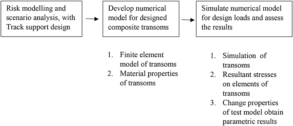
Composite steel-concrete transoms have been designed based on structural guidelines given in the Australian Standard AS3600 (Standards Australia, 2009). Design loads considering the impact of derailments were obtained from the Australian Standard AS5100.2 (Standards Australia, 2004). The precast concrete transoms were numerically modeled to verify the proposed design. A finite element model (FEM) was created using a finite element package, ABAQUS. The validation was previously carried out by very good agreement between numerical results and field measurements (Griffin et al., 2014, 2015). Furthermore, the interactions and internal forces in the steel-precast concrete composite transoms under impact conditions were considered. The risk assessment portrays two possible scenarios with medium and high risk on SHB (see Figure 1). Such the two train derailment situations involve the derailment with train speeds of 5 and 50 km/h, which will be considered in the analyses herein. These speed ranges are very common for metro and suburban rail networks and they could be the representative derailment speeds for the networks. The low derailment speed (5 km/h) correlates to the risk of wheel climbing derailment while the high derailment speed relates to potential damage of wheel sets when traveling around the median train speed (50 km/h). The robustness and resilience of the track slabs are critical to railway systems, especially for metro-suburban passenger traffics. It is thus essential to identify them in order to help railway engineers manage the unlikely crisis better.
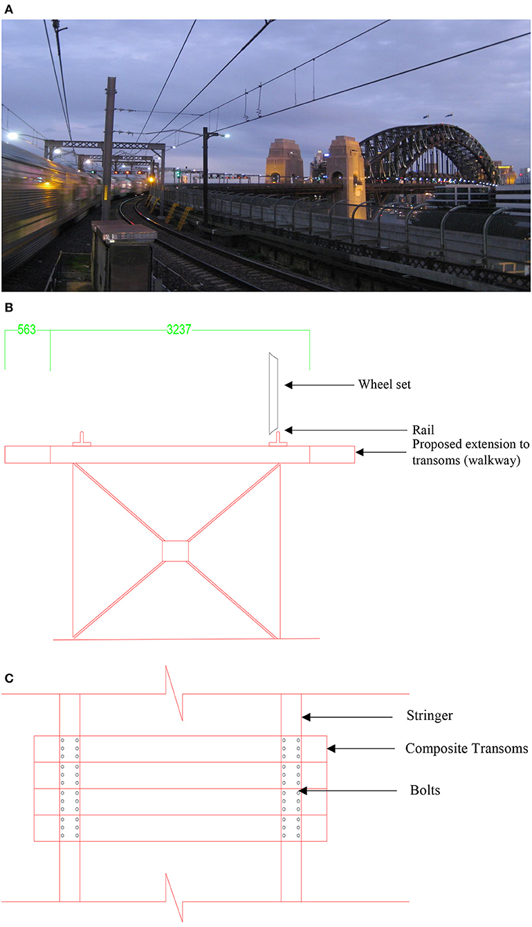
Figure 1. Sydney Harbor Bridge. (A) General view of Sydney Harbor Bridge. (B) Cross section for the structural system of Sydney Harbor Bridge. (C) Top view of the structural system.
Structural System of the Sydney Harbor Bridge
Rails are mounted on transoms and transoms are supported on steel stringers in the SHB. There exists neither ballast nor aggregate materials used under the transoms, in order to transfer and suppress dynamic loadings. Ballast and granular materials play a vital role in uniformly transferring the impact loads from transoms to the ground. It acts as a tensionless spring support. Ballast and granular materials have good damping properties against vibrations. Taking these facts in to account, a simplified structural system was developed for the analysis under dynamic action of loads on transoms in this research as is shown in Figure 1. Transoms are simply supported on stringers and the walk-way has been designed as a cantilever. The proposed composite transoms are connected to the existing steel stringers using headed shear stud connectors. Existing rails then be fastened to the composite transoms using rail pads installed on steel plates.
Design Load Actions on Transoms
Actions of the design loads on transoms shall either be considered in their serviceability and ultimate limit states. LC1, LC2, LC5, and LC10, which will be described later, are considered as the most unfavorable load combinations or the set of worst case scenarios for design according to precedent research (Griffin et al., 2014, 2015). The maximum axial load acting on a transom during a train derailment was taken as 20 tons as per the guide lines established by the transport for New South Wales (Standards Australia, 2004; Remennikov and Kaewunruen, 2008; Kaewunruen and Remennikov, 2015).
Dead Load
The maximum thickness of composite panel will not be increased more than 180 mm due to the limitations of allowable spacing for transoms in the existing structure (limited clearance due to existing overhead wiring structure). Density of concrete is 2,400 kg/m3. Self-weight of concrete transoms is 4.23 kPa. Dead load of services hanged on track was not considered.
Dynamic Load Allowance (DLA)
Dynamic Load Allowance (DLA) is in proportion to the traffic rail way live load (Standards Australia, 2004). This factor increases the live load to be equivalent to the impact of dynamic behavior of the locomotive which induces the live load.
Live Load
Transport of New South Wales recommends a model for the most unfavorable axial loading arrangement live load imposed by a train (Standards Australia, 2004). Model 300LA (a 30t-axle train loading model) shall incorporate a factor for with dynamic load allowance (DLA) to represent the dynamic behavior of the train live load. 300LA Loading arrangement model shown in Figure 2. The load case (300LA) is recommended by Australian Standard AS5100 (Standards Australia, 2004).
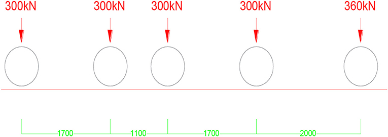
Figure 2. 300LA Axial Loading Configuration (after Standards Australia, 2004).
Design and numerical results obtain by Griffin et al. (2015) were relevant to 300LA, and have revealed the most unfavorable loading arrangement long the rail (worst case scenario).
Loads Due to Thermal Effects
Thermal stresses are also critical in bridges. Thermal movements between various components in deferent material become significant due to the deferent thermal properties of those materials. Horizontal load (F) for L (503 m) > 50 m = 100 + 15(L – 50) = 6,895 kN was considered as braking force; and, as the panels are 0.6 m wide and the breaking force is distributed to two tracks, Q(breaking) of 4.11 kN/m (0.5 × 0.6 × 6,895 kN/503 m) is considered to be transferred to the transom. According to the AS5100.2 (2004), 300LA traffic load produces 100 kN nose load to directions to the structure. Nose load should not be increased in Dynamic Load Allowance (DLA). Q(nose) was considered to be 50 kN/m per track (Mirza et al., 2016a).
Derailment Load
Derailment load was considered in the ultimate load state and would not be increased by DLA. The derailment load is considered as a quasi-static load applying over an area prescribed by Australian Standard AS5100 (Standards Australia, 2004) as shown in Figure 3. The calculation of forces, pressure area and the locations of derailment action can be obtained from the standard to enable the worst-case scenario analyses. Based on the standard, Q(derail) is 133.33kN (Standards Australia, 2004).
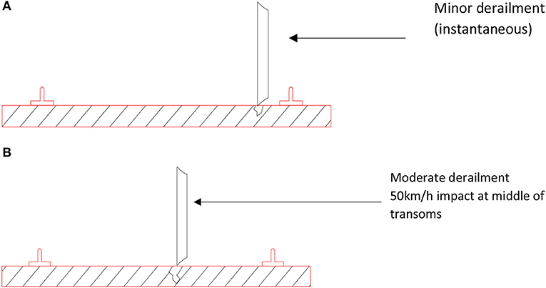
Figure 3. Derailment loading. (A) Minor derailment (high risk). (B) Moderate derailment (moderate risk).
Wind Load
According to the AS5100.2 (2004), design wind speed for the ultimate state is 48 m/s and the design wind speed for the serviceability limit state would be 37 m/s (Standards Australia, 2001). Only the vertical wind load was considered for SHB due to the inclination is less than 5 degrees (Standards Australia, 2004). Ultimate wind pressure was calculated as 1.0368 kPa and the service wind pressure was found to be 0.616 kPa.
load Combinations
Ultimate Limit States
LC1 = 1.4 Gpanel + 3.2 Q200LA + 1.6 Qbreaking (Panel UDL + Pad UDL)
LC2 = 1.4 Gpanel + 2.67 Q200LA + 1.6 Qbreaking (Panel UDL + Pad UDL) LC3 = 1.4 Gpanel + 1.5 Qgeneral (Panel UDL)
LC4 = 1.4 Gpanel + 1.6 Qnose (Panel UDL and Longitudinal point load)
LC5 = 1.4 Gpanel + 1.2 Qderail (Panel UDL and point load)
LC6 = 1.4 Gpanel + 1 W*vu (Panel UDL + wind)
LC7 = Gpanel + Q200LA + Qbreaking + W*vu (Panel UDL and Pad UDL.
Serviceability Limit State
LC10 = 1.2 Gpanel + 2 Q200LA + 0.7 W*vs.
Resultant live load arrangement on transom is given in Figure 4A. Live loads would act as uniformly distributed loads.
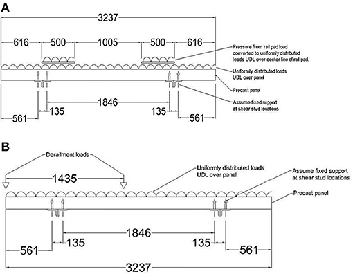
Figure 4. Load Arrangement on transoms. (A) Live Load in accordance with AS5100. (B) Derailment Loading in accordance with AS5100.
The load arrangement due to the impact of derailment is given in Figure 4B. Derailment load would be applied as point loads on locations shown in the figure.
Structural Properties of Elements
Rails, Rail pads, and stingers are the existing structural elements in the model and Composite transoms are only the new element (Kaewunruen and Remennikov, 2009, 2010). Following structural properties for steel (in Table 1) and concrete (in Table 2) are considered.
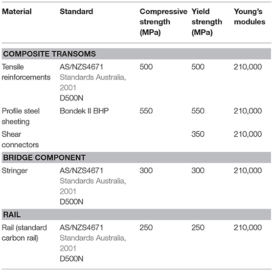
Table 1. The properties of steel elements used in design.
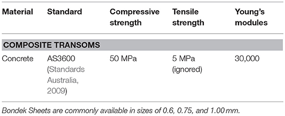
Table 2. The properties of concrete elements used in design.
Structural Analysis and Design of Transoms
Transoms are analyzed for the load cases developed earlier. Linear elastic analysis have been investigated using Microstran to assess load actions and corresponding critical stress locations. Bending moment and shear force diagrams, shown in Figures 5A,B respectively, were obtained using Microstran for the ultimate load cases (LC1/2 and LC5, respectively). The structural design of the composite transoms was then carried out in accordance with the AS5100.2 and AS3600 for the composite sections (Standards Australia, 2001, 2004, 2009). Table 3 lists the maximum design values of bending moments and shear forces obtained from the analysis. The design calculation for the proposed composite steel-concrete transoms is summarized in Table 4.
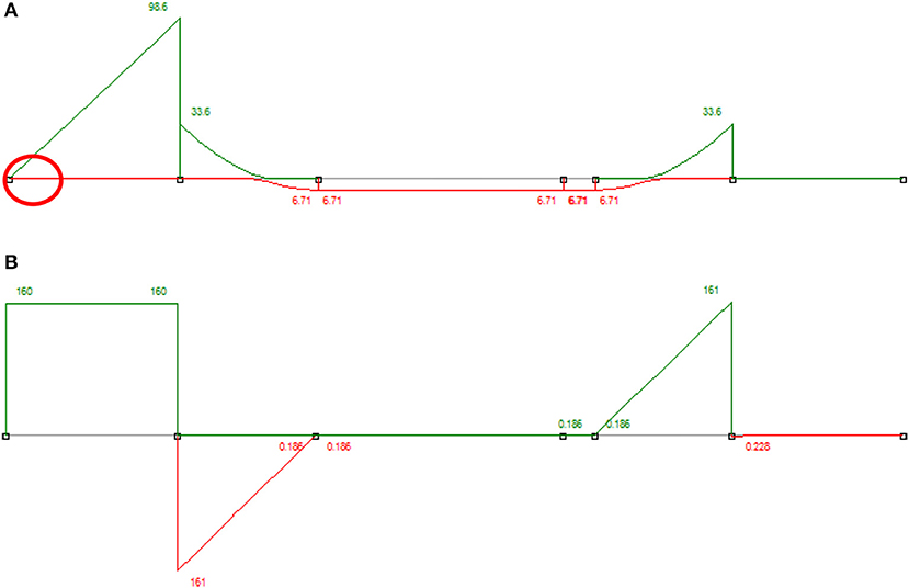
Figure 5. Load effect on the transom. (A) bending moment envelop. (B) Shear force envelop.
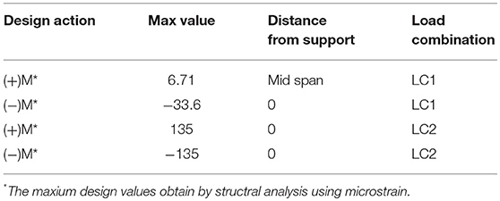
Table 3. Design bending moment envelops.
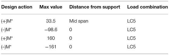
Table 4. Summary of design bending moments.
Summary of the Structural Design Calculation
Table 5 illustrates the major finding in structural design of composite transoms according to the guideline of AS 3600 (Standards Australia, 2009).
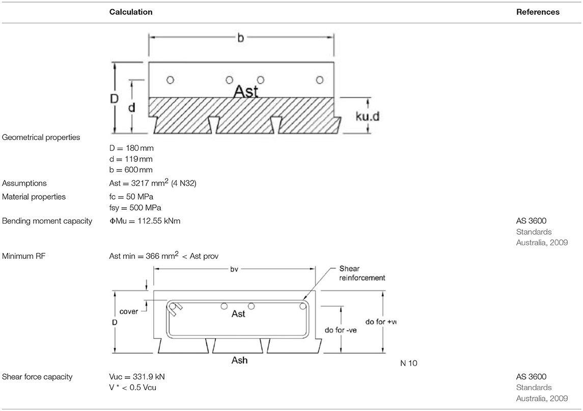
Table 5. Design criteria of composite transoms.
Design Details
The details of the arrangement of the components of the proposed composite steel-concrete transoms are given in Figure 6.
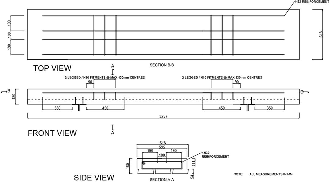
Figure 6. Details of the proposed composite transoms.
Finite Element Modeling
Numerical model was developed using ABAQUS Explicit to simulate the impact of derailment loadings on the proposed steel-concrete composite panel. ABAQUS Explicit can be used to simulate non-linear behavior of the composite transoms in concrete crushing scenarios (Griffin et al., 2015).
Material Properties
In order to benchmark failure modes with structural design code, the material properties used for the design and analysis using the FEM of the composite transoms were obtained from previous studies and assessments (Griffin et al., 2015). The mechanical behaviour of the steel materials is summarized in Table 1. Concrete compressive strengths and elastic moduli of concrete results are summarized in Table 2. The mechanical behavior of the steel materials is summarized in Table 1. The material properties of the components of the FEMs have been represented by constitutive laws and actual material property test data (Remennikov and Kaewunruen, 2006; Zerbst and Beretta, 2011; Klinger et al., 2014; Wu et al., 2014).
Concrete Properties
A concrete damage plasticity model was utilized to describe the actual material behavior for concrete. The material model was found to be suitable for design and modeling (Griffin et al., 2015; Mirza et al., 2016b; Kaewunruen and Kimani, 2017; Kimani and Kaewunruen, 2017). The evolution of the yield (or failure) surface is controlled by tensile and compressive equivalent plastic strains linked to failure mechanisms under tensile and compressive loading. The Concrete Damage Plasticity option is used in conjunction with Concrete Tension Stiffening and Concrete Compression Hardening options in ABAQUS. The flow potential and yield surface parameters have been defined using default values of ABAQUS in the concrete damage plasticity option. The material model for normal weight concrete is used to define the elastic-plastic or curvilinear behavior of concrete for the compressive region. The model is expressed by the following equations, and compression is assumed to be linear elastic up to .
where is the characteristic uniaxial compressive strength of concrete, σc is the uniaxial compressive stress, and εc is the uniaxial strain of the concrete.
In this study, the stress-strain relationship of concrete in tension was assumed to be linear. The tensile stress of concrete increases linearly until concrete begins cracking in tension and decreases linearly to zero from that point. The ratio of the uniaxial tensile stress to the uniaxial compressive stress at failure is evaluated as 0.1. Figure 7A illustrates the stress-strain relationship of concrete according to the compressive behavior and the uniaxial tensile stress-strain behavior of concrete. Strain-rate effect of high strength concrete has been adopted as follows (Kaewunruen and Remennikov, 2011):
where f'c, dyn is the dynamic compressive strength, f'c, st is the static compressive strength of concrete, ε is the dynamic strain, εc0,st is the static ultimate strain, and is the strain rate in concrete fiber.
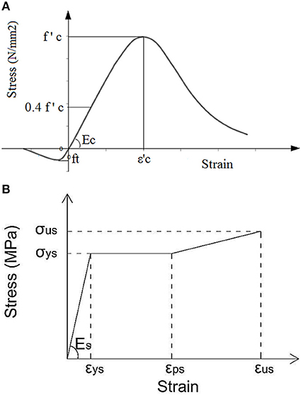
Figure 7. Material properties. (A) Stress-strain curve for normal concrete. (B) Stress-strain curve for structural steel.
Steel Properties
Figure 7B illustrates the stress-strain relationships of the steel materials used to model the profile sheeting, rail, train wheels, reinforcing steel, and welded shear studs respectively. Steel materials generally exhibit elastic behavior up to their yield points and this is followed by further yielding or strain hardening before fracture. The stress-strain relationships of the materials were converted into piecewise linear curves. Strain-rate effect of high strength steel has been adopted as follows (Kaewunruen and Remennikov, 2011):
where fy, dyn is the dynamic upper yield point stress, f'c, st is the static upper yield point stress, and is the strain rate in high strength steel. In this study, high strain rate properties of materials have not been fully considered. This is because this study focuses on a scenario when the damaged train on a straight viaduct often reduces its speed significantly before it derails (Australian Transport Safety Bureau, 2014). The strain rate in these cases tends to be relatively low. However, more work on transient impact and high strain rates will be investigated in the future (Kaewunruen and Remennikov, 2008; Choi et al., 2010; Crawford, 2011).
Geometry, Element Type, and Mesh
For design purpose, the maximum influences on the composite transoms of single wheel derailment have been considered in the derailment model as is illustrated in Figure 5. Due to the loading, which is applied on the stringer not being of importance, the project being conducted will only need the use of half model to produce accurate results. The concrete slab and steel components were modeled using the eight-node linear hexahedral solid elements with reduced integration and hourglass control (C3D8R). Elements with reduced-integration have been adopted as they could reduce computing run time. These elements were incorporated in a reasonably fine mesh in order to improve the accuracy of these models. The mesh sizes were also verified by carrying out a sensitivity analysis. The shear connectors were modeled using second order three-dimensional 20-node quadratic brick elements with reduced integration (C3D20R). The connectors were modeled to represent the actual geometric size and shape within the limitations of the application. The reinforcing bars were modeled with two-node linear three-dimensional truss elements (T3D2).
Contact Properties, Boundary Conditions, and Load Application
The interactions between different parts of the FEM were modeled using general interaction and constraint options available in ABAQUS. Table 6 details the contact behavior between different parts of the FEM. The symmetrical model considered in this project is the derailment panel. The derailment model was considered as symmetrical and all boundary conditions were applied on the section which has been cut. The derailment model as illustrated in Figure 8 is symmetrical about the x-axis. In addition, the Surface 1 of the model is also defined as a symmetrical surface and the nodes of the concrete and Bondek II that lies on that surface was restricted from translating in the z-direction. The sliced section of the stringer is labeled as Surface 2 and the nodes of this area have been restrained from rotation and translation in all three axes, which is defined as Encastre boundary conditions in ABAQUS. The load combination LC5 produced the worst case design actions due to the applied derailment loads in microstran. Therefore, the loads resulting from LC5 have been adopted for the simulations of derailment models. The expected impact loading scenarios were created using dynamic explicit step functions. Loads applied onto the panel are representative of the wheel of the train derailing and causing impact on the panel itself.
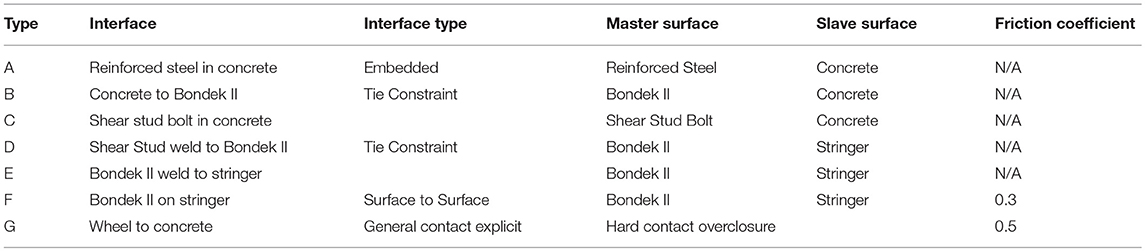
Table 6. Interaction between components of FEM.
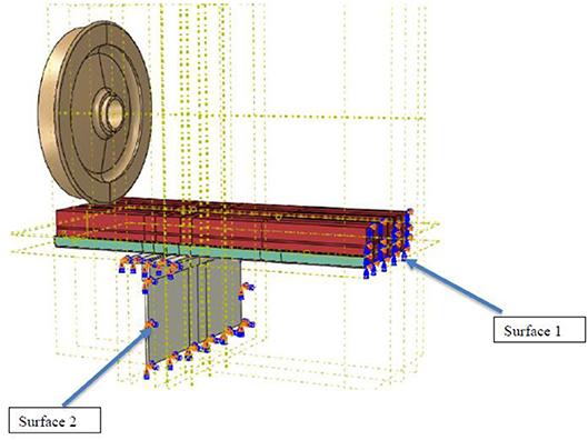
Figure 8. Boundary conditions in the finite element model.
Results and Discussion
Developed design methodology was tested by a simulation of train wheel derailments using a FEM developed in ABAQUS. Results obtained from the FEM, were compared with the proposed design results. The impact of design parameters on the design strengths of the steel-concrete composite transoms was studied by carrying out a detailed parametric analysis. The maximum stresses developed in the composite transom were studied.
Panel Design Results
The composite panels are 180 mm in depth maintaining the same dimensions of the current hardwood timber panels which are not designed to take derailment loadings. The transoms require 4 N32 reinforcement bars throughout the length of the transom and must have a minimum of 54 mm of cover to avoid corrosion. There is no shear reinforcement needed in the panels due to achieving a low enough design shear force (V*). N10 minimum shear reinforcement will be used to fix the tensile reinforcements in place before pouring concrete. Table 7 displays the design actions and design capacities which were obtained from the transom. The design ratio is a quick indication that the design capacity is greater than the design action and must be >1.
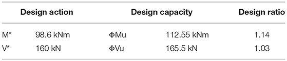
Table 7. Derailment design capacities.
Numerical Analysis Results
Stresses Developed in the Reinforcing Steel and Concrete Panel
The applied dynamic impact was represented by a function of time. The force applied to the transom by the derailment was modeled as an incremental force with the time. Figures 9A,B illustrate the development of the stresses in the reinforcing steel and concrete respectively. The reinforcing steel commenced yielding before concrete started cracking due to compression failure.
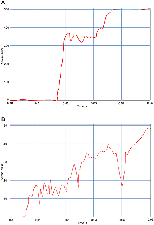
Figure 9. Stresses developed in structural elements. (A) Stresses developed in reinforcing steel (worst-case location). (B) Stresses developed in concrete (worst-case location).
Stresses Developed in the Profiled Sheet (Bondek II)
The graph distribution in Figure 10A displays the resulting stress levels carried by the Bondek II at impact caused by derailment. The derailment relationship of the Bondek II is shown as stress vs. time. From initial impact at time 0, the graph displays a linear curve up until about time 0.004, this is due to the combination of concrete and steel taking load. The maximum stress is reached at time 0.005 with a value of 550 MPa and fluctuates up until time 0.015. Beyond time 0.02 the stress level is reached and is maintained constant. Figure 10B displays the deformed model of the Bondek II caused at the impact once the wheel interacts with the panel. The diagram clearly depicts deformations in the region which the train wheel impacts the panel, this region is highlighted in the mesh with red color located in areas labeled (Y). This maximum stress distribution travels from the point of impact at deformation of the Bondek II and travels toward the shear stud locations. The maximum stress exerted on the Bondek II reaches 550 MPa. This value is the maximum yield stress of the Bondek II. Therefore the yield limit for the Bondek II is reached, and notably does not surpass this point.
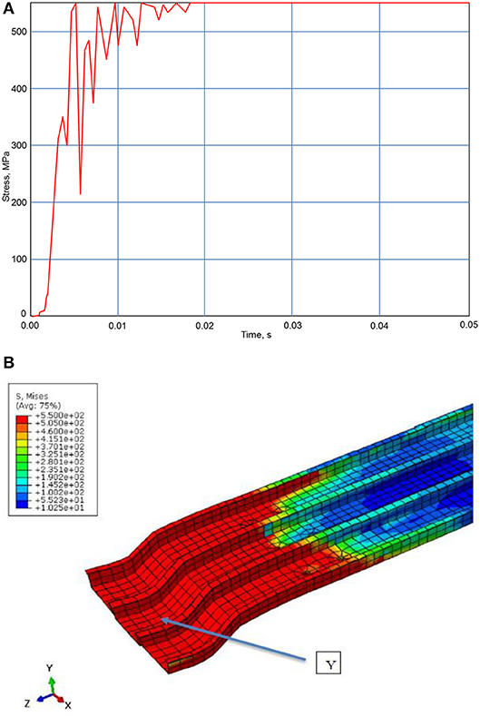
Figure 10. Load effects in the profile element. (A) Stresses developed in the profile sheet. (B) Deformed model of the profile sheet.
Parametric Studies
A detailed parametric study was carried out using the FEM to assess the effect of concrete compressive strength, tensile reinforcement strength, and Bondek II strength on the failure behavior of the composite transoms under impact loading due to train derailments. Prototype model developed by ABAQUS will be tested using a displacement control method. The maximum allowable stresses developed in the structural element was determine by controlling the displacement in allowable limit. This was repeated for deferent strength parameters of concrete, reinforcement steel and Bondek sheets.
The Effect of Concrete Compressive Strength
The concrete strengths including 32, 40, 50, 65, 80, and 100 MPa were modeled. Figure 11 illustrates the relationship between the maximum stress developed in concrete of the transoms and the characteristic compressive strength of the concrete used. The results suggest that the maximum stress in concrete of the transoms increases with increasing concrete compressive strength. However, an unusual pattern was noticed that at 50 MPa concrete strength the maximum stress of the transoms was quite higher than that with the 65 MPa concrete. Furthermore, the transoms with 65 MPa concrete displayed a higher maximum stress than that with 80 MPa concrete and that difference was approximately 2 MPa. Theoretically however, since the transom with 50 MPa has a maximum stress of 48–49 MPa, selecting this option in practice would be realistically better in real life application, however needs experimental testing to validate further.
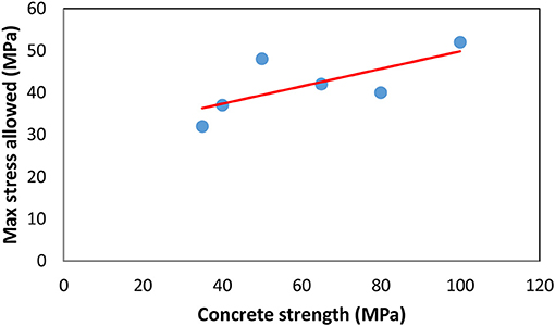
Figure 11. Variation of stresses in concrete vs. characteristic strength of concrete.
The Effect of the Reinforcing Steel
A parametric study for area of tensile reinforcement was explored, whether a higher value of tensile reinforcement will increase the strength and most importantly the serviceability limit. The diameters of steel tensile reinforcement include 33, 36, and 40 mm diameters. The results as shown in Figure 12 indicated that changing of tensile steel reinforcement size does not have a significant effect on the deflection of the panel.
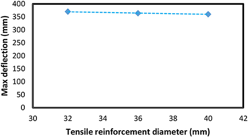
Figure 12. Maximum deflection vs. Diameter of reinforcements.
The Effect of the Yield Strength of the Profile Sheet
Different yield strengths of the profile sheet were considered in the parametric analysis in order to study the maximum stresses developed in the panel. The material properties change from 550 to 800 MPa. The relationship of maximum allowable stresses vs. Bondek II properties was proposed and is shown Figure 13. The study demonstrated that the maximum allowable stress increases linearly with increasing Bondek II yield strength. However, there was a maximum allowable stress value for the profile sheet could take, that was 700 MPa. This was shown in the FE results when 800 MPa Bondek II strength was used, the allowable stress did not increase. Note that the stress over the profile sheet can be reduced by increasing depth of the concrete or the steel sheet itself. With higher strength of concrete, the stress can also be further alleviated.
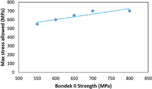
Figure 13. Maximum stress in Bondek sheets vs. Tensile strength of Bondek.
Conclusion
Composite panels can be effectively used as a replacement of timber transoms in SHB. There are various approaches in designing the composite transoms, which can be adopted in finding design solution. In this study, primarily provisions given in the Australian standards for structural concrete design was adopted in order to design the proposed composite steel-concrete transoms. The same depth of 180 mm in the existing system was resembled for composite slabs to avoid any changes to the level of existing structure. Moderate derailment condition while the train is traveling in 50 km/h speed was considered in the design based on the systems risk assessment. The design should be verified by testing a prototype. Numerical model was developed for the prototype testing.
The FEM results suggested, that the reinforcing steel commenced yield before the compressive stress in concrete arrived its characteristic strength due to the impact loading. Therefore, this result indicates that the designed composite transoms are ductile. The Bondek sheets commenced yielding even before the yielding of reinforcement commenced. Stain compatibility was not observed between Bondek and concrete. It was sign of slap between the Bondek sheet and the concrete panel. A detailed parametric study was carried out using the FEM, to understand the effect of concrete compressive strength, tensile reinforcement area and Bondek II strength on the behavior of the composite transoms under impact loading due to train derailments. The deflection of the composite transom under the design load would govern the strength of transom. This was the deflection control method of determination of allowable stress in the structural component. Allowable stresses in components of the composite transom could also be determined experimentally in the simulation by controlling the deflection. Stresses developed in various components were observed for deferent characteristic strength of the materials. The maximum allowable stress in concrete increased with increasing characteristic compressive strength of concrete. Elastic moduli of concrete increase with the increment of the characteristic strength of concrete.
There was no relationship between area of reinforcements and the deflection of the composite ransom. These critical design parameters, which govern the deflection, would rather be some other parameter than the reinforcement area. Theoretically, area of reinforcement has nominal effect on stiffness of panel. In order to decrease the deflection of the composite transom panels, that future studies explore the possibility of incorporating pre-stressed steel in the panel could be suggested. Defection control test simulation was done to find out the relationship between strength of Bondek sheet (yield strength) and the allowable stress. The allowable stress increased linearly until the yield strength of Bondek sheet increased to 700 MPa.
Further Research
This research has been limited to equivalent static load analysis to the dynamic impact of the loads over the bridge. This method could be justified by AS5100.2 (Standards Australia, 2004). In a Further research the entire bridge can be modeled and modal analysis can be performed to understand the response of the structure to the dynamic loads imposed by train live loads and derailments (Kaewunruen and Kimani, 2018; Mirza and Kaewunruen, 2018). Response Spectrum Density Function could be developed to model the train live loads based on actual data.
Author Contributions
OM and SK developed the design concept. OM performed the analyses. SK provided field data for model validation. OM and SK wrote and contributed their thoughts and experience to the paper.
Conflict of Interest Statement
The authors declare that the research was conducted in the absence of any commercial or financial relationships that could be construed as a potential conflict of interest.
The reviewer RY declared a past co-authorship with one of the authors SK to the handling editor.
Acknowledgments
Technical assistance from Salvatore Macri, Aleksandar Devic, and Saan Asmaro are gratefully acknowledged. The verification part of this study has been presented in the 24th UK ACME Conference 2016 (Kaewunruen et al., 2016). The conference does not have the copyright of materials used in this paper. The authors are sincerely grateful to European Commission for the financial sponsorship of the H2020-MSCA-RISE Project No. 691135 RISEN: Rail Infrastructure Systems Engineering Network, which enables a global research network that tackles the grand challenge in railway infrastructure resilience under physical natural and unnatural threats as well as its advanced sensing (Kaewunruen et al., 2016). The first author wishes to thank Western Sydney University for her Early Career Research Award. Also, the second author wishes to gratefully acknowledge the Japan Society for Promotion of Science (JSPS) for his JSPS Invitation Research Fellowship (Long-term), Grant No. L15701 at Track Dynamics Laboratory, Railway Technical Research Institute and at Concrete Laboratory, the University of Tokyo, Tokyo, Japan.
Footnotes
1. ^https://www.thetimes.co.uk/article/23-killed-in-kalinga-utkal-express-train-derailment-en-route-to-haridwar-hn5cl3dtm.
References
Australian Transport Safety Bureau (2014). Derailment of Sydney Trains Passenger Train 602M, ATSB Transport Safety Report Rail Occurrence Investigation RO-2014-001, Australian Capital Territory, Commonwealth of Australia. Available online at: https://www.atsb.gov.au/publications/investigation_reports/2014/rair/ro-2014-001/
Brabie, D., and Andersson, E. (2006). Dynamic simulation of derailments and its consequences. Vehicle Syst. Dyn. 44 (Suppl. 1), 652–662. doi: 10.1080/00423110600882753
Brabie, D., and Andersson, E. (2008). Post-derailment dynamic simulation of rail vehicles – methodology and applications. Int. J. Vehicle Mech. Mobil. 46, 289–300. doi: 10.1080/00423110801939162
Choi, J., Park, Y., Choi, E., and Choi, J. (2010). Applying precast slab panel track to replace timber track in an existing steel plate girder railway bridge. J. Rail Rapid Transit. 224, 159–167. doi: 10.1243/09544097JRRT333
Crawford, R. H. (2011). Greenhouse gas emissions embodied in reinforced concrete and timber railway sleepers. Environ. Sci. Technol. 43, 3885–3890. doi: 10.1021/es8023836
Fang, Q., and Zhang, J. (2013). Three-dimensional modelling of steel fiber reinforced concrete material under intense dynamic loading. Construct. Build. Mater. 44, 118–32. doi: 10.1016/j.conbuildmat.2013.02.067
Griffin, D., Mirza, O., Kwok, K., and Kaewunruen, S. (2014). Composite slabs for railway construction and maintenance: a mechanistic review. IES J. A Civil Struct. Eng. 7, 243–262. doi: 10.1080/19373260.2014.947909
Griffin, D., Mirza, O., Kwok, K., and Kaewunruen, S. (2015). Finite element modelling of modular precast composites for railway track support structure: a battle to save Sydney Harbour Bridge. Aust. J. Struct. Eng. 16, 150–168. doi: 10.1080/13287982.2015.11465187
Gu, G., and Franklin, F. J. (2010). Application of the structural articulation method to dynamic impact loading of railway bridges – a case study. Vehicle Syst. Dynam. 48, 1097–1113. doi: 10.1080/00423110903406672
Ju, S. H. (2014). A simple finite element for nonlinear wheel/rail contact and separation simulations. J. Vibrat. Control 20, 330–338. doi: 10.1177/1077546312463753
Kaewunruen, S., Griffin, D. W. P., Mirza, O., and Kwok, K. (2015a). “Resilience-based design of precast steel-concrete composites for railway track slabs,” in Proceedings of the 13th International Railway Engineering Conference (Edinburgh).
Kaewunruen, S., and Kimani, S. K. (2017). Damped frequencies of precast modular steel-concrete composite railway track slabs. Steel Comp. Struct. 24, 427–442. doi: 10.12989/scs.2017.25.4.427
Kaewunruen, S., and Kimani, S. K. (2018). “Dynamic mode couplings of railway composite track slabs,” in Proceedings of the Institution of Civil Engineering – Structures and Buildings (London).
Kaewunruen, S., Mirza, O., and Thomson, D. (2016). “Responses and vulnerability of composite railway track slab to train derailments,” in Proceedings of the 24th UK Conference of the Association for Computational Mechanics in Engineering (Cardiff).
Kaewunruen, S., and Remennikov, A. M. (2008). Experimental simulation of the railway ballast by resilient materials and its verification by modal testing. Exp. Tech. 32, 29–35. doi: 10.1111/j.1747-1567.2007.00298.x
Kaewunruen, S., and Remennikov, A. M. (2009). Impact capacity of railway prestressed concrete sleepers. Eng. Fail. Anal. 16, 1520–1532. doi: 10.1016/j.engfailanal.2008.09.026
Kaewunruen, S., and Remennikov, A. M. (2010). Dynamic properties of railway track and its components: recent findings and future research direction. Insight Non Destruct. Test Cond. Monit. 52, 20–22. doi: 10.1784/insi.2010.52.1.20
Kaewunruen, S., and Remennikov, A. M. (2011). Experiments into impact behaviour of railway prestressed concrete sleepers. Eng. Fail. Anal. 18, 2305–2315. doi: 10.1016/j.engfailanal.2011.08.007
Kaewunruen, S., and Remennikov, A. M. (2015). “Impact responses of prestressing tendons in railway concrete sleepers in high-speed rail environments,” in Proceedings of the 5th International Conference on Computational Methods in Structural Dynamics and Earthquake Engineering (Rhodes).
Kaewunruen, S., Sussman, J. M., and Einstein, H. H. (2015b). Strategic framework to achieve carbon-efficient construction and maintenance of railway infrastructure systems. Front. Environ. Sci. 3:6. doi: 10.3389/fenvs.2015.00006
Kaewunruen, S., Sussman, J. M., and Matsumoto, A. (2016). Grand challenges in transportation and transit systems. Front. Built Environ. 2:4. doi: 10.3389/fbuil.2016.00004
Kimani, S. K., and Kaewunruen, S. (2017). Free vibrations of precast modular steel-concrete composite railway track slabs. Steel Comp. Struct. Int. J. 24, 113–128. doi: 10.12989/scs.2017.24.1.113
Klinger, C., Michael, T.h., and Bettge, C. (2014). Fatigue cracks in railway bridge hangers due to wind induced vibrations – failure analysis, measures and remaining service life estimation. Eng. Fail. Anal. 43, 232–252. doi: 10.1016/j.engfailanal.2014.02.019
Krezo, S., Mirza, O., He, Y., and Kaewunruen, S. (2016a). “Bootstrap statistical analysis of GHG emission from railway maintenance and renewal projects,” in Proceedings of the Third International Conference on Railway Technology: Research, Development and Maintenance, ed J. Pombo (Stirlingshire: Civil-Comp Press). doi: 10.4203/ccp.110.300
Krezo, S., Mirza, O., He, Y., Makim, P., and Kaewunruen, S. (2016b). Field investigation and parametric study of greenhouse gas emissions from railway plain-line renewals. Transport. Res. D Trans. Environ. 42, 77–90. doi: 10.1016/j.trd.2015.10.021
Mirza, O., and Kaewunruen, S. (2018). Influence of shear bolt connections on modular precast steel-concrete composites for track support structures. Steel Comp. Struct. 27, 647–659. doi: 10.12989/scs.2018.27.5.647
Mirza, O., Kaewunruen, S., Dinh, C., and Pervanic, E (2016a). Numerical investigation into thermal load responses of railway transom bridge. Eng. Fail. Anal. 60, 280–295. doi: 10.1016/j.engfailanal.2015.11.054
Mirza, O., Kaewunruen, S., Kwok, K., and Griffin, D. W. P. (2016b). Design and modelling of pre-cast steel-concrete composites for resilient railway track slabs. Steel Comp. Struct. Int. J. 22, 537–565. doi: 10.12989/scs.2016.22.3.537
Remennikov, A. M., and Kaewunruen, S. (2006). “Impact resistance of reinforced concrete columns: experimental studies and design considerations,” in Proceedings of the 19th Australasian Conference on the Mechanics of Structures and Materials (Christchurch), 817–824.
Remennikov, A. M., and Kaewunruen, S. (2008). A review of loading conditions for railway track structures due to train and track vertical interaction. Struct. Cont. Health Monit. 15, 207–234. doi: 10.1002/stc.227
The Guardian (2016). Grayrigg Train Crash. Available online at: http://www.theguardian.com/uk/grayrigg-train-crash.
Wu, X., Chi, M., and Gao, H. (2014). The study of post-derailment dynamic behavior of railway vehicle based on running tests. Eng. Fail. Anal. 44, 382–339. doi: 10.1016/j.engfailanal.2014.05.021
Keywords: railway bridge, steel-concrete composite, transom, impact damage, failure analysis, dynamic finite elements, resilience, robustness
Citation: Mirza O and Kaewunruen S (2018) Resilience and Robustness of Composite Steel and Precast Concrete Track Slabs Exposed to Train Derailments. Front. Built Environ. 4:60. doi: 10.3389/fbuil.2018.00060
Received: 17 November 2017; Accepted: 10 October 2018;
Published: 14 November 2018.
Edited by:
Zili Li, Delft University of Technology, NetherlandsReviewed by:
Yan Quan Sun, Central Queensland University, AustraliaRuilin You, China Academy of Railway Sciences, China
Sumit Chakraborty, Indian Institute of Engineering Science and Technology, Shibpur, India
Copyright © 2018 Mirza and Kaewunruen. This is an open-access article distributed under the terms of the Creative Commons Attribution License (CC BY). The use, distribution or reproduction in other forums is permitted, provided the original author(s) and the copyright owner(s) are credited and that the original publication in this journal is cited, in accordance with accepted academic practice. No use, distribution or reproduction is permitted which does not comply with these terms.
*Correspondence: Sakdirat Kaewunruen, cy5rYWV3dW5ydWVuQGJoYW0uYWMudWs=