- 1Wrocław University of Science and Technology, Wrocław, Poland
- 2Research & Design Office Mosty-Wrocław, Wrocław, Poland
- 3Budimex S.A., Warsaw, Poland
The road and railway infrastructure in Poland has been intensively developed and modernized for the last years. Around 300 new bridges are built annually. Among the new structures, there is a group of modern extradosed bridges. This paper presents examples of short-, medium-, and long-span extradosed bridges designed and built in recent years in Poland. The following structures are described in details: (1) the first Polish extradosed bridge; (2) two-span landmark viaduct over motorway; (3) multi-span curved motorway bridge; (4) the longest Polish extradosed bridge; (5) tramway extradosed bridge; and (6) conceptual designs. The paper is concluded with geometrical parameters characterizing presented structures. The parameters are compared with values obtained for cable-stayed bridges and extradosed bridges built worldwide.
Introduction
The extradosed bridge is a relatively new type of structure that has been developed since the 1990s. The first such structure was the Odawara Blueway bridge, which was designed and constructed in Japan (Shirono et al., 1993). The extradosed bridge can be defined as the structure being between the girder bridge and the cable-stayed bridge (Mermigas, 2008; Collings and Gonzalez, 2013). The key feature visually distinguishing the extradosed bridge from the cable-stayed bridge is the low tower height above the deck and hence shallow stay angles. Another specific feature of the extradosed bridges is the larger girder stiffness in comparison to that of the cable-stayed bridges. Stays in the extradosed bridges can be stressed to a relatively high level, similar to used in prestressed girder structures, since the stress variation under live loads in stays is usually lower in comparison with the cable-stayed bridges (Kasuga, 2006; Mermigas, 2008).
Short-Span Bridges
Bridge in Konin (2007)
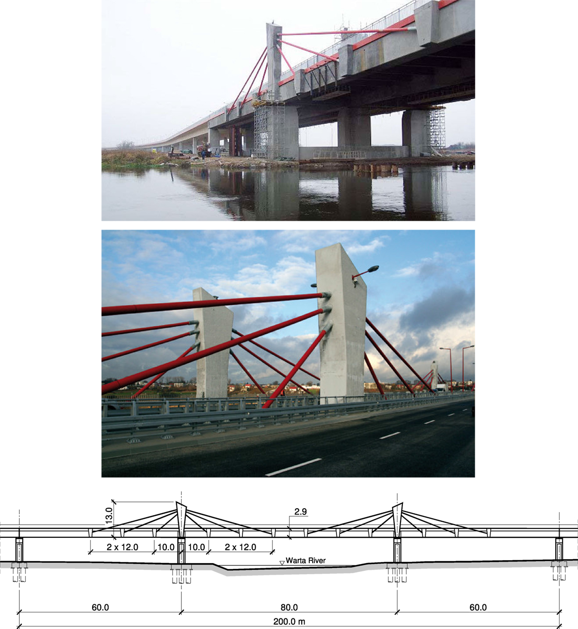
The bridge over the Warta River in Konin was the first extradosed bridge built in Poland. It is located along the road connecting urban street network of the city of Konin with the A2 motorway. A dual carriageway three-span bridge with a total length of 200 m and spans of 60.0 + 80.0 + 60.0 m was built over the main riverbed of the Warta River. The superstructure is a concrete beam–slab deck (three main girders) suspended to low pylons fixed in the deck. The main girders have a height of 2.6 m, and the width of the bridge is 25.1 m. The deck has concrete crossbeams over the supports and steel plate crossbeams interacting with concrete elements of the section in the spans.
The pylons are 10.3-m high and have a variable cross-section (Figure 1). The external stays consist of 37 or 42 steel strands (with a diameter of 15.7 mm) conducted in HDPE sheath tubes filled with cement grout. The active anchorage blocks are located at the outer surfaces of the side girders and under the internal girder. The superstructure was built using the incremental launching method. Each of the girders was separately launched using a steel launching nose. Next construction stages included assembly of steel crossbeams, concreting the deck slab, pylons, and installation of the external stays.
The bridge in Konin was designed by Transprojekt Gdański.
Viaduct over the S8 Expressway in Oleśnica (2012)
The Viaduct situated near Oleśnica is an extradosed two-span structure made of prestressed concrete class C40/50 with spans of 43.50 + 39.90 m (Biliszczuk et al., 2013). The Viaduct is curved in plan. Skew angle of the spans varies from 32.5° to 46.5°. In the cross-section it is a beam–deck structure with two side girders and a low deck plate. Prestressing continuous internal tendons from the spans are conducted over the middle support as external cables of large eccentricity. They are deviated in steel saddles encased in low pylons of variable cross-section (Figure 2).
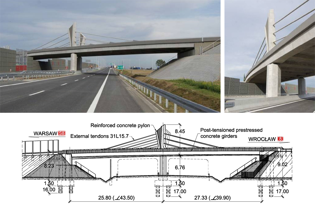
Figure 2. Viaduct near Oleśnica—views of completed structure and elevation drawing (design: Research & Design Office Mosty-Wrocław).
Middle- and Long-Span Bridges
Bridge over the Motława River in Gdańsk (2012)
The extradosed bridge over the Motława River can be considered the most interesting structure along the southern ring road of Gdańsk, which is a part of the S7 expressway. It is a prestressed concrete three-span structure, with the main span of 135 m and the total length of 290 m (Figure 3). The bridge has two separate parallel superstructures, one for each of the roadways, designed in the form of two widely spaced box girders braced by truss steel crossbeams. External stays have a harp arrangement and are anchored in column pylons fixed in massive concrete crossbeams on both sides of each superstructure. The superstructure was longitudinally launched with use of temporary supports.
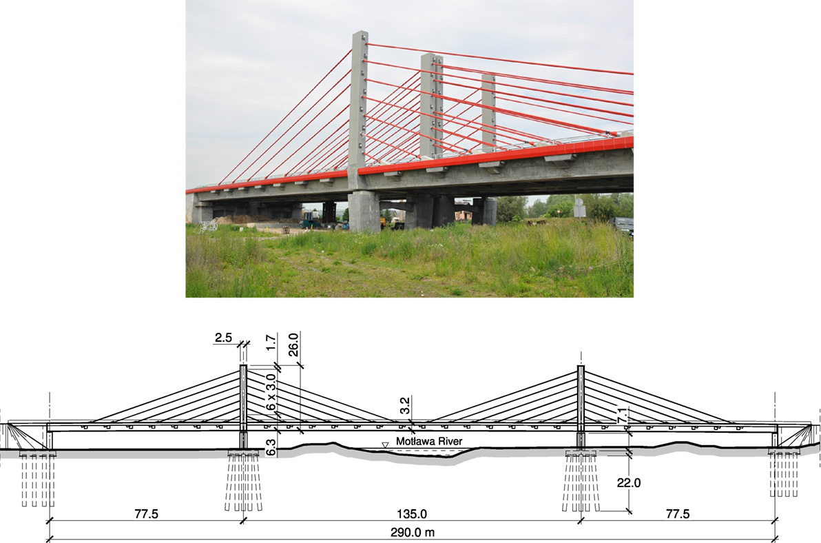
Figure 3. Bridge in Gdańsk—view during construction and elevation drawing (design: Transprojekt Gdańsk and Mosty Gdańsk).
Bridge along the A1 Motorway in Mszana (2014)
The bridge near the village of Mszana is located in the zone of the motorway junction and leads the A1 motorway across the valley of the Kolejówka stream. Described bridge has a single wide prestressed concrete box superstructure for both motorway carriageways (concrete class C50/60 and C60/75). It is curved in plan and has four spans of 60.0 + (2 × 130.0) + 60.0 m. The double-cell box girder has a height variable from 2.60 m in the mid-span to 4.00 m over the supports.
There is only a single plane of double external stays situated in the axis of the bridge. The stays (each consisting of 43 strands with a diameter of 15.7 mm) are anchored in 3 hybrid steel–concrete column pylons (each with a height of 15.1 m above the deck level), located along the central web of the box girder (Figure 4). Active anchorages of the stays are located inside the box girder, on sides of the central web, and passive anchorages are situated in the pylons.
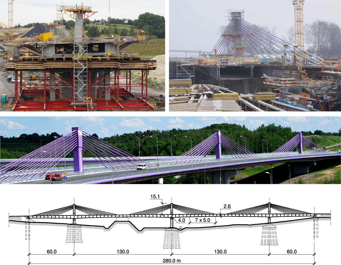
Figure 4. Bridge in Mszana—views during construction, view of completed structure (photo: M. Prusak), and elevation drawing.
Structural configuration of the bridge is significantly complicated by the connection of the slip road flyover in the central section of one of the spans. For this reason, the width of the bridge is variable and ranges from 38.58 up to 47.45 m. Untypical configuration of the bridge and assumed design solutions were the cause of a number of difficulties during its construction and caused a significant delay in its completion. The bridge in Mszana was finally opened to traffic in 2014.
This bridge was designed by Complex Projekt.
Bridge over the Vistula River in Kwidzyn (2013)
Construction of the bridge in Kwidzyn crossing the Vistula River, situated along the new section of the road DK90, was one of the most important investments in the transportation network of Pomerania region (northern Poland). It allowed to link the city of Kwidzyn with the A1 motorway.
The new bridge consists of five structures with a total length of 1,867 m. The main 808-m long bridge crossing the riverbed is a six-span extradosed continuous beam with spans of 70.0 + 130.0 + (2 × 204.0) + 130.0 + 70.0 m (Zawiła, 2014; Biliszczuk et al., 2016). Design and construction of such long-span extradosed bridge was a pioneering undertaking in Europe.
The superstructure is a single-cell concrete box girder with inclined webs and a constant height of 3.50 m. External stays are anchored in edge beams stiffened by transversal beams. The webs with a typical width of 0.40 m are locally widened in the support zones to 0.60 m, and the thickness of the bottom plate is increased to 0.80 m. The small structural height of the box girder constant along the whole length of the bridge, which is untypical for such long spans (Kasuga, 2006), required to use high strength concrete (C70/80) for the first time in Polish bridge engineering.
Short concrete pylons acting as deviators of external stays are fixed in the superstructure and are made of the same high strength concrete. Each pylon has the shape of two inclined columns with the height of 17.2 m above the deck level, which is only about 1/12th of the span. The post-tensioning system consists of internal cables and external cables and stays. External stays consisting of 75 7-wire strands are conducted outside the cross-section of the span. The strands are deflected in steel saddles placed in the pylons and are anchored in concrete blocks in the edge beams of the deck.
The spans of the bridge in Kwidzyn were constructed section-by-section using underslung movable scaffolding (Zawiła, 2014). The superstructure was divided into 12 sections, each 50-m long. For this purpose it was necessary to build 13 temporary concrete supports, 6 of which were located in the river current (Figure 5).
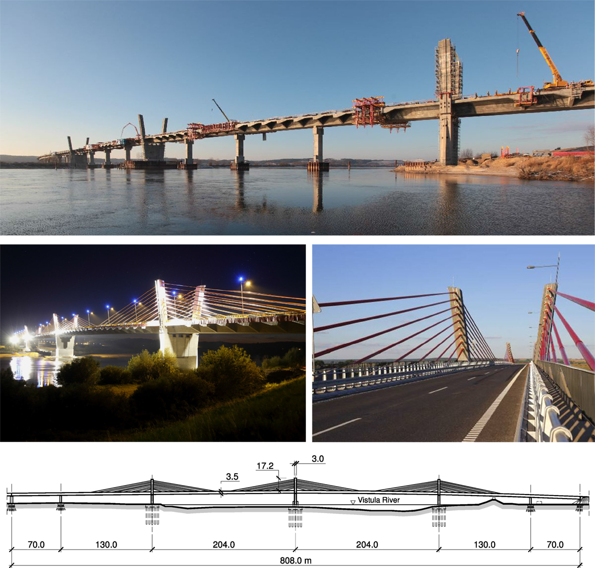
Figure 5. Bridge in Kwidzyn—view during construction, views of completed structure (photo: Budimex), and elevation drawing.
The bridge was designed by Transprojekt Gdańsk and constructed by Budimex.
Long-span extradosed bridges can be treated to some extent as an alternative to the cable-stayed bridges. A comparison of the bridge in Kwidzyn with the largest Polish concrete cable-stayed bridge—the Rędziński Bridge in Wrocław (Biliszczuk et al., 2014) in terms of basic material consumption (concrete and prestressing steel) and unit costs is presented in Biliszczuk et al. (2016). Obtained results indicate that a concrete extradosed structure with a span of about 200 m can be economical in comparison with a large-span concrete cable-stayed bridge.
Tramway Flyover along the KST Line in Cracow (2015)
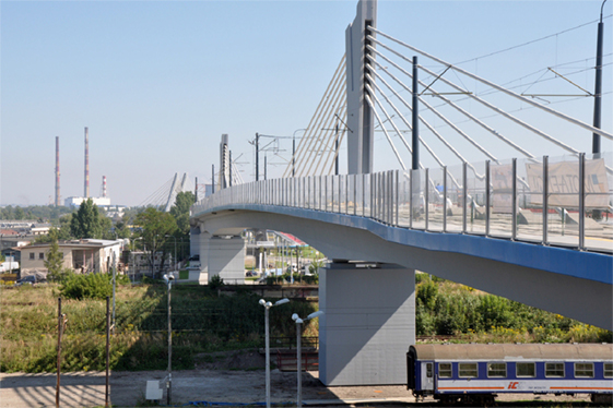
Described multi-span extradosed flyover is a part of the new section of the Cracow Fast Tram (KST) line and is the longest tramway flyover in Poland. The route crosses platforms of Kraków Płaszów railway station and connects two large city districts. The flyover has been integrated with the area of the railway station by providing direct access to the platforms by stairs and elevator.
The flyover is a seven-span beam with the longest 100-m spans tensioned by external stays. The stays are anchored along the axis of the deck and deflected in saddles placed in three short pylons. The deck is an asymmetric single-cell box girder of variable height (Figure 6). Wider plate overhang is the place for a sidewalk and a bicycle path. In the sections where the stays are anchored, the box girder is stiffened with diagonal high strength steel bars. Due to the location in an urbanized area (above the platforms of the railway station and local streets), the main spans were erected by the balanced-cantilever method. The first stage of construction included concreting the starting segment and the pylon. Subsequent segments with a length of ≈5.7 m were cast in situ with the use of a form traveler.
The KST flyover was designed by PxM Projekt Południe.
Conceptual Designs and Ongoing Projects
One of the first concepts of the extradosed bridge in Poland was developed for the flyover over Świebodzki railway station in Wrocław in 2000. Proposed concept assumed construction of a six-span, steel–concrete composite flyover, and with a low structural height. The longest 60-m spans were suspended to three steel V-shaped pylons situated in the axis of the deck (Figure 7A). The superstructure consisted of three steel box girders composite with a concrete deck slab and a system of closely spaced crossbeams.
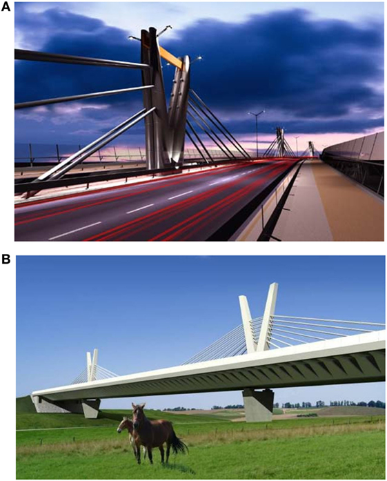
Figure 7. Concepts of extradosed bridges: (A) viaduct in Wrocław—computer visualization and (B) computer image of the bridge over the Łyna River (design: Research & Design Office Mosty-Wrocław).
The bridge over the Łyna River was designed in 2012 as a part of the ring road of Olsztyn, crossing the valley filled with marshy peat bog (Biliszczuk et al., 2013). It is a concrete extradosed structure with a single superstructure for both carriageways, with spans of 60.0 + 120.0 + 60.0 m. The superstructure is a single box girder, 4.00 m high, made of prestressed concrete. Deck overhangs are supported by concrete struts, designed in the form of precast concrete triangular slabs. Main girder is be post-tensioned by internal tendons and external cables conducted through the low V-shaped pylons, fixed in the deck. The external cables are deflected in steel saddles and anchored in the box girder. Figure 7B shows computer images of the bridge over the Łyna River.
The bridge in Kwidzyn stands out among the extradosed bridges built worldwide and can be treated as a flagship of Polish civil engineering. But this is not the last word. At the moment (2016), a longest extradosed bridge is in the initial construction stage. It will have two 206-m long spans (Figure 8) and will be located along a dual carriageway ring road of the city of Ostróda.
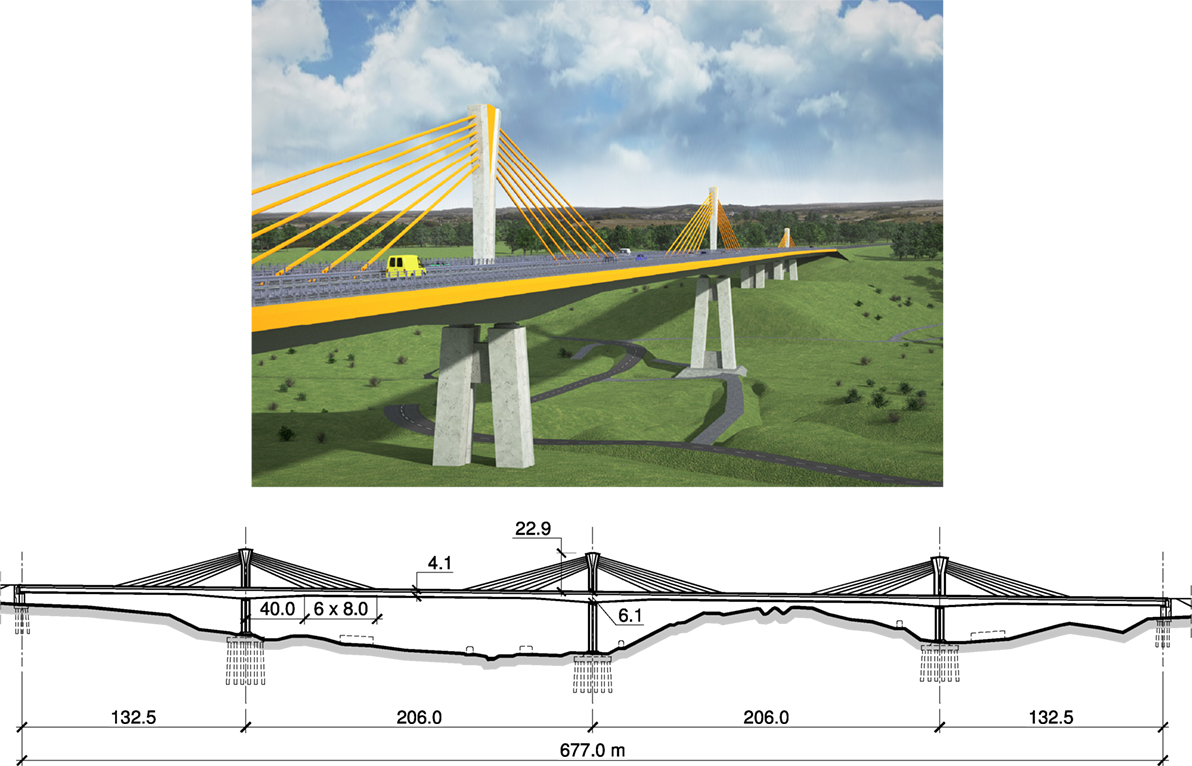
Figure 8. Visualization of the extradosed bridge with 206-m long spans (author: T. Stefanowski, Transprojekt Gdański).
Geometrical Parameters of Extradosed Bridges
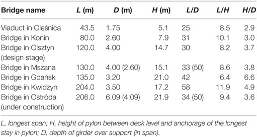
The main dimensions (L—length of span, H—height of pylon between deck level and anchorage of the longest stay in pylon, D—depth of girder) of bridges described in this paper are presented in Table 1. Depth of girder is given over support and in span (in brackets) if it varies along the span. Table 1 also summarizes parameters (ratios) L/D, L/H, and H/D characterizing geometrical form of extradosed bridges.
Data given in Table 1 show that the stiffness of the main girder expressed by L/D ratio is in the range 25–35 in most cases and it decreases along with the span length. In most cases the described structures have a constant deck depth. Span to height ratios (L/H) range from 6 to 12 (in most cases L/H ≈ 9), and H/D ratio is usually in the range 3–4.
Collected data show that the bridge in Kwidzyn deserves a special mentioning among presented structures. It is characterized both by the highest L/H and L/D ratio and has a record span in Poland and in Europe. Material consumption indices obtained in the case of this bridge were highly advantageous in comparison with a cable-stayed concrete bridge with a similar span (Biliszczuk et al., 2016).
It is reasonable to compare the geometrical parameters of extradosed bridges with those of girder and cable-stayed bridges. Figure 9 shows relationship between the deck depth D (at the tower support) and the span length L for those types of bridges built worldwide (Collings and Gonzalez, 2013). The extradosed bridges built in Poland, summarized in Table 1, have been additionally placed on the diagram. It can be seen that extradosed bridges are a separate class of bridges, situated between girder and cable-stayed bridges, although the boundaries are not so evident. Polish structures fit well in the trend line obtained for extradosed, with the exception of the bridge in Kwidzyn, which is characterized by a high span to depth ratio (L/D = 58) resulting from the constant deck depth, which is uncommon solution for a large-span structure of this type (Kasuga, 2006).
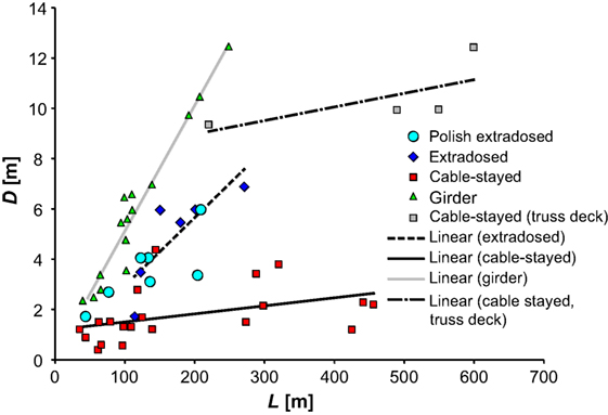
Figure 9. Deck depth versus length of span (Collings and Gonzalez, 2013) including examples of Polish extradosed bridges.
A similar diagram is presented in Figure 10 illustrating the relationship between the height of pylon H and the span L for extradosed and cable-stayed bridges (Collings and Gonzalez, 2013), including data collected on Polish structures. This diagram shows another feature distinguishing extradosed bridges—low pylons. Their height is about 0.4 of the height typical for cable-stayed bridges with the span in the range of 100–200 m.
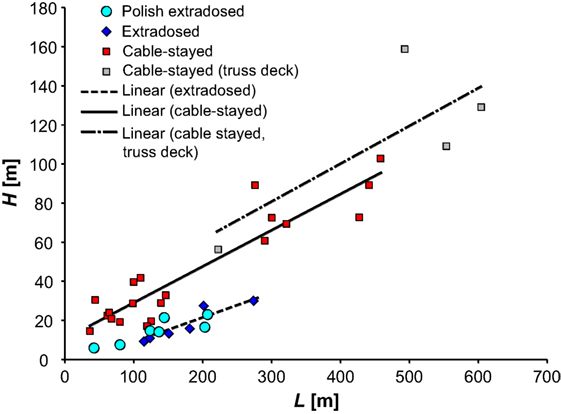
Figure 10. Pylon height versus length of span (Collings and Gonzalez, 2013) including examples of Polish extradosed bridges.
Figure 11 presents span to tower height ratio (L/H) versus tower height to girder depth ratio (H/D) for cable-stayed and extradosed bridges built worldwide (Collings and Gonzalez, 2013) and in Poland. It is evident that the extradosed bridges have similar H/D ratio and similar L/H ratio. Scattering of these parameters is much larger in cable-stayed bridges, due to the multiplicity of architectural and structural forms of this bridge type. Data show that there is no clear boundary between both bridge groups.
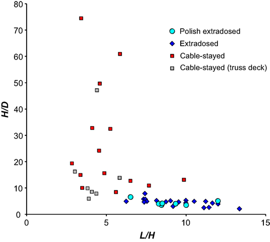
Figure 11. Plot of geometrical parameters L/H and H/D (Collings and Gonzalez, 2013) including examples of Polish extradosed bridges.
Conclusion
This paper presents some details of design and construction of selected extradosed bridges designed and built in recent years in Poland. The extradosed bridges, despite their relatively short history, have found their place among other bridge types and are more and more often designed and constructed. In the term of costs, they can be competitive in comparison to even 200-m long cable-stayed bridges (Biliszczuk et al., 2016). The extradosed bridges can also be an attractive proposition for relatively small landmark structures (e.g., built over motorways) and can compete with beam and arch bridges.
A different issue is the assessment of architectural attractiveness of the extradosed bridges in comparison to girder and cable-stayed bridges. The cable-stayed bridges usually strongly dominate surrounding, while the extradosed bridges characterized by horizontal lines are more neutral and have less aggressive visual impact on the surroundings. Nevertheless, they can be visually more attractive in comparison to the simple girder bridges.
Author Contributions
Each of the authors prepared a part of the manuscript.
Conflict of Interest Statement
The authors declare that the research was conducted in the absence of any commercial or financial relationships that could be construed as a potential conflict of interest.
References
Biliszczuk, J., Barcik, W., Onysyk, J., Toczkiewicz, R., Tukendorf, A., and Tukendorf, K. (2014). Rędziński Bridge in Wrocław – the largest concrete cable-stayed bridge in Poland. Struct. Eng. Int. 24, 285–292. doi: 10.2749/101686614X13830790993087
Biliszczuk, J., Onysyk, J., Barcik, W., Toczkiewicz, R., and Tukendorf, A. (2013). “Pioneering concrete cable-stayed bridges in Poland,” in Proceedings of the Fib Symposium Engineering a Concrete Future: Technology, Modeling & Construction (Tel-Aviv), 657–660.
Biliszczuk, J., Onysyk, J., Barcik, W., Toczkiewicz, R., and Tukendorf, A. (2016). The two largest Polish concrete bridges – design and construction. Bridge Eng. 169, 298–308. doi:10.1680/jbren.15.00015
Collings, D., and Gonzalez, A. S. (2013). Extradosed and cable-stayed bridges, exploring the boundaries. Bridge Eng. 166, 231–239. doi:10.1680/bren.10.00058
Kasuga, A. (2006). Extradosed bridges in Japan. Struct. Concr. 7, 91–103. doi:10.1680/stco.2006.7.3.91
Shirono, Y., Takuwa, I., Kasuga, A., and Okamoto, H. (1993). “The design of an extradosed prestressed concrete bridge – the Odawara Port Bridge,” in Proceedings of the FIP Symposium 93 (Kyoto, Japan), 959–966.
Keywords: extradosed bridge, prestressed concrete, design, construction technology, geometrical parameter
Citation: Biliszczuk J, Onysyk J, Barcik W, Toczkiewicz R and Tukendorf A (2017) Extradosed Bridges in Poland—Design and Construction. Front. Built Environ. 2:37. doi: 10.3389/fbuil.2016.00037
Received: 14 July 2016; Accepted: 16 December 2016;
Published: 03 January 2017
Edited by:
Anastasios Sextos, University of Bristol, GreeceReviewed by:
Luigi Di Sarno, University of Sannio, ItalyStergios Mitoulis, University of Surrey, UK
Copyright: © 2017 Biliszczuk, Onysyk, Barcik, Toczkiewicz and Tukendorf. This is an open-access article distributed under the terms of the Creative Commons Attribution License (CC BY). The use, distribution or reproduction in other forums is permitted, provided the original author(s) or licensor are credited and that the original publication in this journal is cited, in accordance with accepted academic practice. No use, distribution or reproduction is permitted which does not comply with these terms.
*Correspondence: Jan Biliszczuk, amFuLmJpbGlzemN6dWsmI3gwMDA0MDtwd3IuZWR1LnBs
 Jan Biliszczuk
 Jerzy Onysyk1,2