- 1Department of Urban Management, Kyoto University, Kyoto, Japan
- 2Department of Civil Engineering, Faculty of Engineering, Chiang Mai University, Chiang Mai, Thailand
- 3Graduate School of Global Environmental Studies, Kyoto University, Kyoto, Japan
- 4Doyu Daichi Limited, Hiroshima, Japan
- 5Doyu Daichi Limited, Osaka, Japan
The effect of near-fault ground displacement is a significant factor when structures straddle a fault, because the fault produces both static step-like deformations and dynamic pulse-like ground motions. It has been observed that the static displacements measured up to 10 m and strong ground motion velocity pulses exceed 100 cm/s. As there is no concrete method for the seismic design of near-fault structures based on earthquake-induced fault displacement, the numerical simulation of near-fault ground motions is of great significance. In this paper, we describe a hybrid method combining stochastic and theoretical Green’s functions for synthesizing near-fault ground motions. Our approach considers the complete waveforms (far-, intermediate-, and near-field terms) of both the dynamic and static terms. To demonstrate the hybrid method, two simple examples of strike-slip and dip-slip fault models are simulated. The results exhibited dynamic displacement with the fling-step of near-fault movement. Furthermore, the 1999 Chi-Chi earthquake in Taiwan is also simulated, and the results showed good agreement with the observed recordings. Thus, the proposed method is a useful tool for evaluating near-fault ground motions for designing bridges and other structures.
Introduction
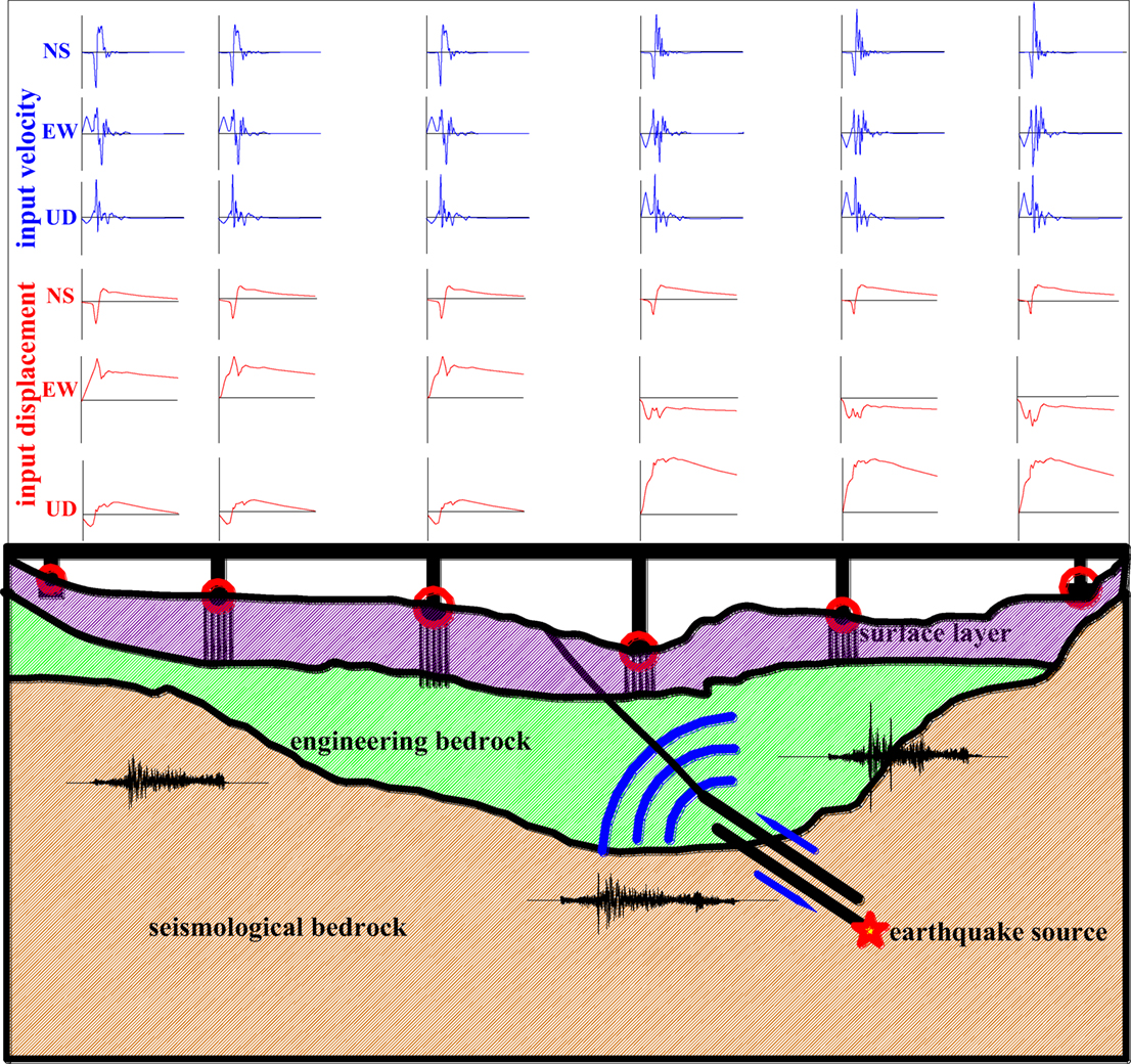
Various facilities and structures have long spatial extents and/or natural periods, such as long-span bridges, embankments, pipelines, and high-rise or base-isolated buildings. A number of these are located in the vicinity of surface faults or across active tectonic faults, e.g., the bridge crossing a fault as illustrated in Figure 1. The ground displacements (as shown in Figures 2A,B) induced by fault activities are important factors in the safety of structures. Recent design philosophies are only based on considering the inertia force, velocity, and dynamic displacement. However, the observed performance of these essential structures following recent earthquakes suggests that conventional design methods do not satisfy the required performance levels for permanent displacement, as shown in Figure 1 (middle part of the displacement waveforms). If there is no other alternative than to locate structures across an active fault, then obtaining the spatially varying strong ground motions, especially the permanent tectonic displacements across the fault, is very useful for seismic design.
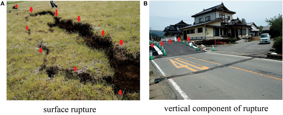
Figure 2. Surface rupture of the 2016 Kumamoto Earthquake (A) surface rupture (B) vertical component of rupture.
Numerous studies have focused on this topic. For instance, Ucak et al. (2014) calculated synthetic broadband ground motions at the location of the Bolu Viadcuct using a hybrid simulation approach in which low-frequency parts were given by a discrete wavenumber representation method and high-frequency parts were obtained by stochastic modeling. Kojima and Takewaki (2015) proposed that a double impulse input can be treated as a substitute for the fling-step near-fault ground motion, while, up to now, no rational seismic design philosophy has been established for structures crossing active faults. Thus, in this paper, we describe a hybrid method to simulate near-fault ground motions. Our method combines the stochastic Green’s function (Irikura, 1983; Irikura and Miyake, 2006) with a theoretical Green’s function method (Hisada, 1994, 1995; Hisada and Bielak, 2003). The stochastic Green’s function method is widely used, especially in Japan. For example, it has been used to estimate the waveforms for the anticipated gigantic Nankai Trough earthquake (see http://www.bousai.go.jp/jishin/nankaii/model/data_teikyou.html, we can fill in the application form to obtain data from the Cabinet Office, Government of Japan). Our motivation is to simulate ground motions based on this widely used stochastic Green’s function method in combination with a method that can accurately express the permanent displacement.
In this paper, we first describe the characteristics of near-fault ground motions. Then, we introduce the proposed hybrid method for near-fault ground motions, including permanent displacements. To evaluate the effectiveness of our approach, the proposed method is applied to two simple fault mechanisms, the strike- and dip-slip faults. Finally, the 1999 Chi-Chi earthquake in Taiwan is simulated to further validate our method.
Characteristics of Near-Fault Ground Motion
Intensive Impulsive Velocity Effect
This effect is observed in the velocity time histories of many strong-motion earthquakes, such as for the 2015 Nepal earthquake in Figure 3A (Parajuli and Kiyono, 2015), and the near-source records of Mian Zu Qing Ping (MZQ, at a distance of about 1.7 km from the fault plane), during the 2008 Wenchuan earthquake, China (Figure 3B), which exhibits a two-sided velocity pulse (Lu et al., 2010). The intensive impulsive velocity effect is induced from the rupture directivity process and occurs in the direction vertical to the fault plane.
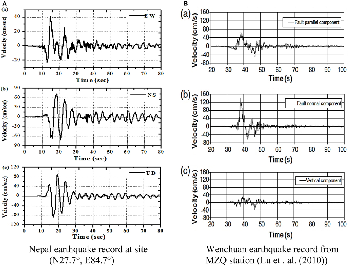
Figure 3. Velocity time histories of near-fault strong ground motions (A) Nepal earthquake record at site (N27.7°, E84.7°), (B) Wenchuan earthquake record from MZQ station Lu et al. (2010).
Permanent Displacement (Fling) Effect
The fling effect is induced from the permanent tectonic offset of a rupturing fault. For example, Figure 4 shows the typical step-like displacements records of Si Fang Ba Jiao (SFB, at a distance of 1.2 km from the fault plane) during the 2008 Wenchuan earthquake and the TCU052 (at 1.7 km to the fault plane) and TCU072 (about 14 km to the fault plane) during the 1999 Chi-Chi, Taiwan, earthquake (Kramer, 1996). These records can be explained by elastic rebound theory. When the shear stress reaches the shear strength of the rock along the fault, the rock fails, and the accumulated strain energy is released. As this rupture progresses, it causes ground motions and induces the permanent displacement of the surface (Lu et al., 2008).
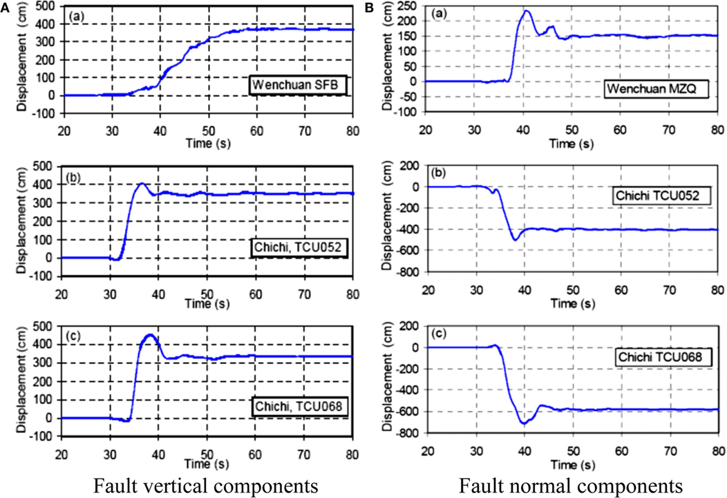
Figure 4. Step-like displacement time histories of near-fault significant earthquake records (A) fault veridical component (B) fault normal component.
Hanging-Wall Effect
The third significant feature is the hanging-wall effect, whereby ground motions at sites located on the hanging wall of a dip-slip fault are larger than at sites located on the footwall at the same distance. Hanging-wall effects have been observed in the records of the 1994 Northridge earthquake and the 1999 Chi-Chi, Taiwan. The main reason for this effect is the wave propagation distance and the multi-reflection and refraction of the propagating waves between the surface and the fault planes (Liu et al., 2006).
Methodology
To simulate the time histories of near-fault ground motions, accurately incorporating the near-fault source radiation pattern is required to account for far- and near-field seismic radiation. The ability to characterize motions for a broad range of fault types (e.g., strike-slip, normal, and reverse faulting) is also important, as are variable slip and full kinematic descriptions of the rupture process. We must be able to accurately simulate the directivity effect as well as the sudden elastic rebound (namely the fling-step). Thus, models must be able to calculate the ground motions very close to the surface fault; here, the fling-step effect and velocity pulses are important characteristics of near-fault ground motions.
Hybrid Method
First, based on the representation theorem, the displacements given by a kinematic fault model can be expressed in the frequency domain as:
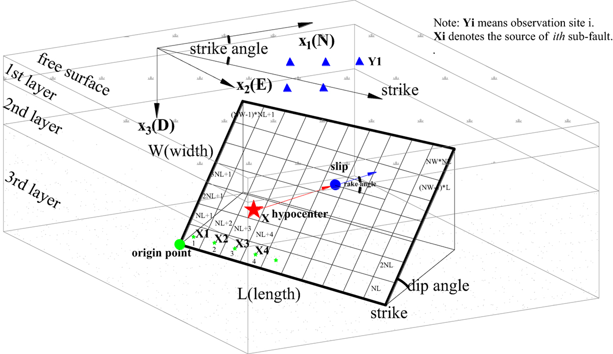
where Uk is the kth component of displacement in Cartesian coordinates at an observation point Y, X is the source point on the fault plane, ω is the circular frequency, S is the fault plane, Tik is the traction Green’s function, and Di is the ith component of the fault slip. The slip rupture model and parameters are shown in Figure 5.
To simulate theoretical strong ground motions for near-faults, Hisada and Bielak (2003) introduced an efficient method for the fault integration of the representation theorem. This method evaluates the fault integration of the dynamic and static terms separately as:
where and are the dynamic and static traction Green’s functions of the layered half-space. On the right-hand side of Eq. 2, the first integral contains the dynamic terms, and the second integral includes the static terms (which means ω = 0).
The stochastic Green’s function method is very popular, flexible, applicable to structural designs, and can also generate dynamic ground displacements in the vicinity of the fault. However, it is difficult to simulate fault movements such as a “static” fling-up (permanent displacement) of the fault. The theoretical Green’s function method can generate both dynamic and static ground motions and has the advantage that the displacement near the fault almost directly reflects the source characteristics. However, its application is limited to idealized layered media and time-consuming. Thus, to incorporate the displacements induced by active faults, the hybrid method of modified stochastic (for dynamic calculations) and theoretical (for static calculations) Green’s functions is proposed for synthesizing the near-fault ground displacement. We shall show that this approach is much faster than some other simulation methods.
Modified Stochastic Green’s Function Method
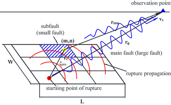
As the observation point is close to the fault plane, the waveforms exhibit sharp peaks of short duration in the region close to the observation point (Hisada and Bielak, 2003) Even if the distance to the fault is very small, the dynamic ground motion can be calculated by superposing small element waveforms. Thus, the stochastic Green’s function method (Irikura, 1983; Irikura and Miyake, 2006) is adopted to calculate the dynamic terms, as shown in Eq. 2. The basic principle of the original statistical Green’s function method is as follows: a large earthquake is composed of a series of small earthquakes and statistically calculated small earthquakes (namely the statistical Green’s function) are properly selected as the ground response caused by small-area sources. That is, statistical Green’s functions are overlaid in a specified manner to obtain the time history of a strong earthquake. Equations 3 and 4 describe the main procedure of this method:
where U(t) is the synthetic main-shock ground motion displacement, u(t) is the observed small ground motion, NL, NW, and ND are the ratios of fault length, fault width, and slip values between large and small events, and tmn is the delay time of the point source (m, n) on the rupture surface. The parameter τ denotes the rise time of a small earthquake, and Vs, VR denote the S-wave velocity near the earthquake source and rupture velocity, respectively. ξmn is the distance from (m, n) located on the fault plane to the starting point, as shown in Figure 6, and n' is an integer that weakens the artificial periodicity of n so that the tick interval represents the sampling rate. The other notation is defined in the schematic diagram of the superposition of small events in Figure 6.
As the conventional stochastic Green’s function method is mainly adopted to generate far-fault ground motions, it only considers the far-field terms of the S-wave. For regions very close to the source, the ground motion features are rather complicated and the attenuation relationship is very different from that of the far-fault ground motions. Thus, the complete waveforms, including the near-, intermediate-, and far-field items of P-waves and S-waves, should be taken into consideration. The complete waveforms have been calculated using a finite-difference method (Dreger et al., 2007), whereas Onishi and Horike (2004) improved the stochastic Green’s function by introducing theoretical radiation coefficients to the P-, SV-, and SH-waves and using a ray tracing technique in the layered half-spaces. In this paper, we introduce a simple model in which the complete waveforms are calculated based on the method proposed by Nozu (2006), which used the ratio of the Fourier transform of the total wave to introduce near-field and intermediate-field terms of P- and S-waves with respect to that of far-field S-wave. This process is described by Eq. 5 [the derivation and more details can be found in Nozu (2006)]. Furthermore, the calculation for far-field P-wave is the same, except that the P-wave velocity is used instead of the S-wave velocity in the radiation pattern.
Theoretical Green’s Function Method
The stochastic Green’s function method does not consider the static displacement, because the statistically calculated small earthquake does not contain permanent displacements. To obtain the near-fault time history, the static terms (second integral on the right-hand side of Eq. 2) describe the attenuation of the slip function due to the static traction of the Green’s function, and the theoretical Green’s function is calculated by the wavenumber integration method (Hisada, 1994, 1995; Hisada and Bielak, 2003). In this study, we only use the second term of Eq. 2, and calculate the static displacement as:
where Uk(Y; ω) is the static displacement (in this situation, ω = 0), and Di is the same as in Eq. 1. Clearly, it is very easy to calculate Eq. 6; the details can be seen in Figure 5.
Synthesis of Near-Fault Ground Motions
To further describe the proposed approach, we applied the combined method to synthesize ground motions for two simple and idealized surface fault models: strike-slip and dip-slip fault in the homogeneous half-space.
Example 1: Strike-Slip Fault Model
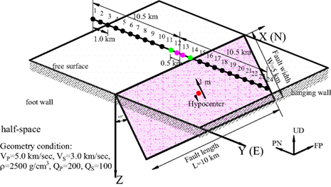
First, a simple and pure strike-slip model of surface faulting (see Figure 7) was simulated by taking into account both the static and dynamic terms of the near-field ground motions. In Figure 7A, the fault size is 10.0 km in length and 5.0 km in width, with strike angles of N0°E, a dip angle of 90°, and rake angle of 0°, and the seismic moments were set to Mo = 3.825 × 1025 dyne cm. Surface observation points (numbered 1–12) were calculated along a line perpendicular to the fault plane. Note that points 1 and 2 are only 100 m and 500 m away from the fault trace, respectively. Similarly, points 3–12 are 1.5~10.5 km away from the fault trace at intervals of 1.0 km. The characteristic fault model is shown in Figure 7B, which was divided into 10 × 5 sub-faults, the asperity has a slip of 1.0 m, stress drop of 141.0 bar and slip of 0.6285 m, stress drop of 28.8 bar for the background. Another important parameter is the slip velocity function; we assume it has the form of an isosceles triangle with 1.0-s duration here. The homogeneous half-space with physical properties is also described in Figure 7A. The static terms are calculated by the proposed representation theorem, Eq. 6, and the dynamic terms are simulated by a modified statistical Green’s function.
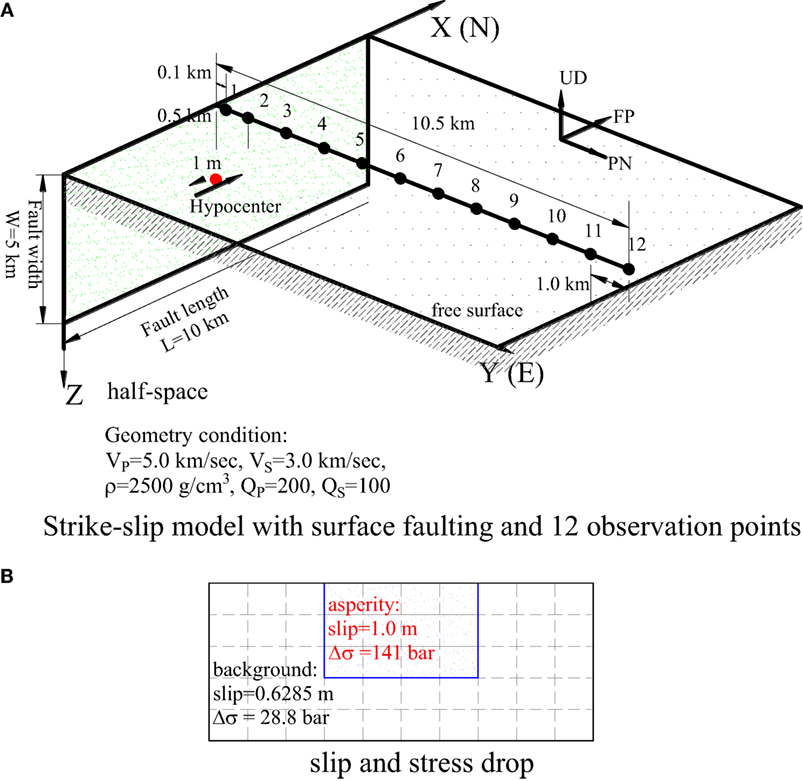
Figure 7. Strike-slip model. (A) Strike-slip model with surface faulting and 12 observation points. (B) Slip and stress drop.
The symmetry of the model indicates that this is a pure strike-slip fault. The fault-normal components (namely along the EW direction) are very small, and the vertical components are negligible compared with the fault-parallel components. Thus, only the calculated velocity and displacement time histories along the fault-normal direction are shown in Figures 8A–F. As mentioned above, the near-fault ground motion is rather complicated.
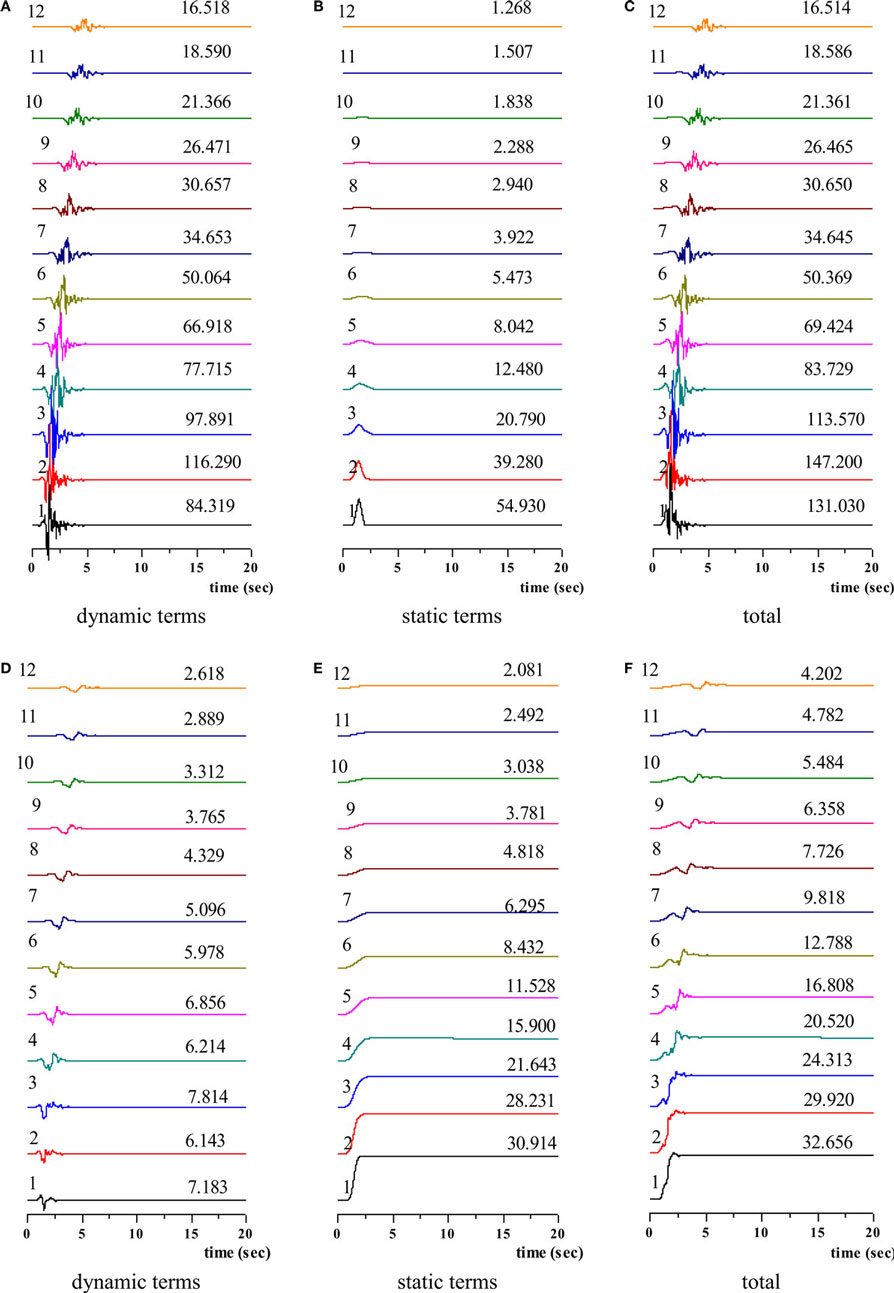
Figure 8. Simulated time histories of velocity [(A) dynamic terms (B) static terms (C) total] and displacement [(D) dynamic terms (E) static terms (F) total] along fault-parallel (NS) direction (Note: the left numbers present the observation point, right numbers present the peak values).
For dynamic terms, in Figure 8A, the velocity time histories for observation points 1~4 (at distances of 0.1~3.5 km from the fault traction) exhibit random dynamic peak values, whereas at sites 4~12, the peak dynamic terms exhibit a degree of attenuation. Somerville (1998) obtained an empirical relationship for the variation of the PGV (peak ground velocity) as a function of the moment magnitude and the distance to the causative fault, assuming that PGV varies as for distances larger than 3.0 km. The simulated velocity time histories exhibit this tendency. The displacement time histories of dynamic terms in Figure 8D also illustrate that the peak displacements of dynamic terms not only exhibit pure time delay but also have a random distribution located very near the causative fault.
For the static terms, Figures 8B,E show that the peak values of velocity and displacement attenuate with distance from the surface fault traction. Compared with the dynamic terms, this decrease is more pronounced. In this situation, almost all the static terms are larger than the dynamic displacements in Figure 8E, which confirms that the permanent displacements should not be neglected when designing near-fault bridges or pipelines.
In the results given by the theoretical Green’s function method, the attenuation is different: very near the fault traction, the static terms are dominant, whereas further away from the fault traction, the dynamic terms prevail. As different analysis methods have been applied here, these differences are acceptable because the hybrid method considers the complete waveforms of the dynamic terms; according to Nozu (2006), the near-fault ground motion is heavily dependent on the frequency and velocity. This illustrates that the near-fault ground motion is rather complicated.
Example 2: Dip-Slip Fault Model
Next, we calculated the near-fault strong motions using a dip-slip surface faulting model. The fault model is shown in Figure 9, with strike angles of N0°E, a dip angle of 45°, and rake angle of 90°(reverse fault), and the seismic moment was Mo = 3.825 × 1025 dyne cm. Here, 24 observation points were positioned on the free surface along the line perpendicular to the fault traction; points 1~12 were located on the footwall, and points 13~24 were on the hanging-wall side. Points 12 and 13 were closest to the fault trace, 100 m on either side, with points 11 and 14 of 500 m away from the fault trace. Points 1~10 and 15~24 were arranged at intervals of 1.0 km. The characteristic fault model with slip distribution and the stress drop was schematically the same as example 1 shown in Figure 7B, and slip function was also assumed as triangle with duration of 1.0 s. The material properties of the layered half-space are also shown in Figure 9.
As this reverse-fault model considers a pure dip-slip fault, the simulated results along the fault-normal (EW) and up–down directions are analyzed. Figures 10A–F show the results along the fault-normal direction, and Figures 11A–F showed the simulation time histories along the up–down direction, including the dynamic terms, static terms, and total velocity and displacement at the 24 observation points.
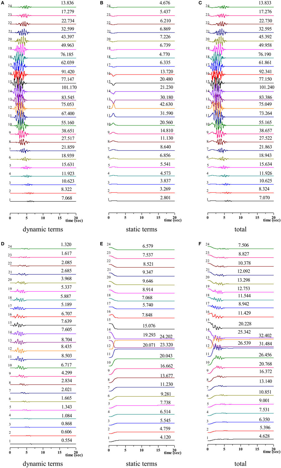
Figure 10. Simulated time histories of velocity [(A) dynamic terms (B) static terms, (C) total] and displacement [(D) dynamic terms (E) static terms (F) total] along EW direction (Note: the left numbers present the observation point, right numbers present the peak values).
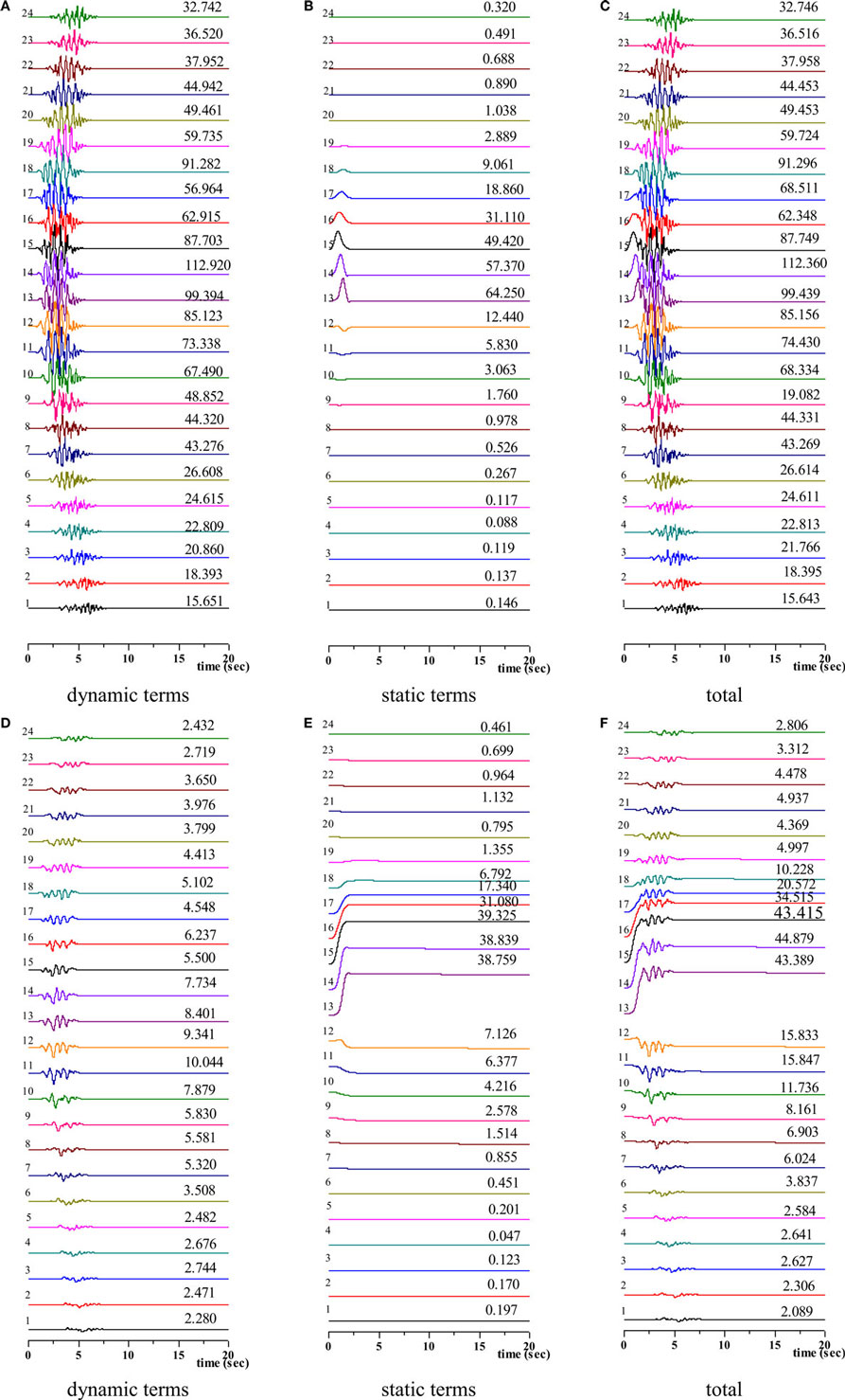
Figure 11. Simulated time histories of velocity [(A) dynamic terms (B) static terms, (C) total] and displacement [(D) dynamic terms (E) static terms (F) total] along up–down direction (Note: the left numbers present the observation point, right numbers present the peak values).
For the EW direction, the velocity time histories in Figure 10A indicated that there are no major differences between the sites located on the hanging wall or the footwall side; the dynamic terms are all larger than the static velocity as compared with Figures 10A,B, whereas the static displacements (Figure 10E) are all larger than the dynamic displacements in Figure 10D. Thus, the permanent displacements should be considered when conducting a seismic analysis of near-fault spatially expanded structures.
Along the up–down direction in Figure 11, the results illustrate the hang-wall effect, i.e., the observation points on the hang-wall indicate larger motions than the observation sites on the footwall, especially the static terms of both velocity in Figure 11A and displacement in Figure 11D.
As the distance from the fault trace increases, the static displacements attenuate rapidly, and the dynamic components become dominant, the same attenuate tendency as in strike-slip fault model.
Synthesis of Strong Ground Motions for the 1999 Chi-Chi Earthquake
Fault Model
The proposed hybrid method was used to simulate the time histories of near-fault ground motions on the 1999 Chi-Chi earthquake in Taiwan, including the permanent displacements.
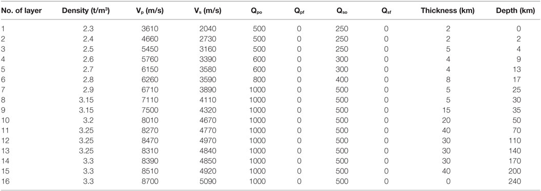
The 1999 Chi-Chi earthquake (Mw 7.6; September 20, 1999, 14:47:15.9 UTC; hypocenter located at 23.853°N, 120.816°E at a depth of 7.5 km) inflicted severe regional-scale damage on Taiwan. The surface fracture trace ran along the Chelunpu fault, with strike angles of N5°E and a dip angle of 30°. According to Wu’s (Wu et al., 2001) fault model A and Hisada’s simulation (Hisada, 0000), the fracture had a length and width of 82 and 42 km, respectively. The characteristic fault model with two asperities is plotted in Figure 12B. The fault plane was divided into 21 × 11 sub-faults, and the seismic moments were set to Moa1 = 8.2315 × 1025 for asperity 1, Moa2 = 6.3874 × 1025 for asperity 2, and Mob = 5.2829 × 10²² for the background of each sub-fault. In addition, the 16-layer soil conditions are listed in Table 1.
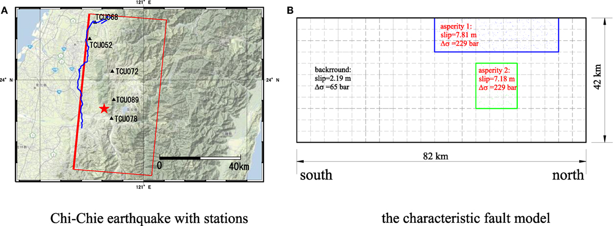
Figure 12. Recording station of Chi-Chi earthquake and fault plane (A) source model of Chi-Chi earthquake and recording stations (B) the characteristic fault model.
We used a rupture velocity of 3.0 km/s, rake angle of 60°, and calculated the ground motions at four observation sites on the hanging wall which shown in Figure 12A, TCU052 (1.7 km away from the surface fault traction), TCU072 (14.2 km away from the surface fault traction), TCU089 (16.4 km away from the surface fault traction), and TCU078 (16.2 km away from the surface fault traction). For the slip velocity, we considered five time windows, based on Nakamura and Miyatake (1997). Note that band-pass filters (0.0~0.01 Hz and 10.0~15.0 Hz) and baseline correction were applied in processing the results.
Simulated Results
For reasons of limited space, we only present the results from two stations, TCU052 and TCU072, including the velocity in Figure 13 and displacement in Figure 14 time histories and comparisons with the observed recordings.
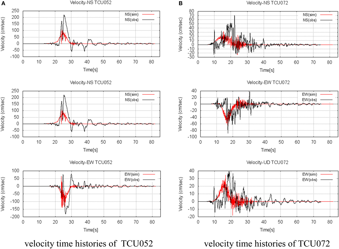
Figure 13. Observed (black line) and simulated (red line) waves for the velocity time histories, along the NS-, EW-, and UD-direction, respectively. (A) velocity time histories of TCU052 (B) velocity time histories of TCU072.
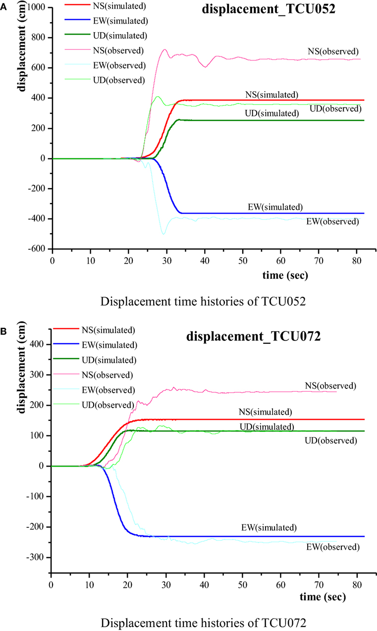
Figure 14. Observed (thick line) and simulated (bold line) waves for the displacement time histories, along the NS-, EW-, UD-direction for (A) TCU052 and (B) TCU072, respectively.
For the velocity time histories in Figure 13, the simulated velocities along three directions are smaller than the observed waves at TCT052 and generally fit well with the observed velocities at TCU072. As the near-fault ground motions are highly dependent on the frequency in the proposed method, it is clear that high-frequency regions affect the simulated results.
In the displacement time histories shown in Figure 14, the vibrations of the simulated results are not so obvious in the waveforms, which suggest that the dynamic parts are smaller than the static terms. The simulated displacement along the NS direction for both TCU052 and TCU072 are notably different to the observed recordings. The displacement along the UD direction at TCU052 in Figure 14A is a little smaller than the observed movement. The other simulated displacements are in good agreement with the observations, which showed that the proposed hybrid method could effectively simulate the near-fault strong ground motions.
Conclusion
In this paper, we have proposed a hybrid method to simulate strong ground motions in near-fault areas for the seismic design of bridge structures. The following conclusions can be stated.
(1) In the proposed hybrid method, the modified stochastic Green’s function method was combined with the theoretical Green’s function method to simulate the displacement and velocity time histories of near-fault ground motions. This method advantages that it can synthesize near-fault ground motions faster and more efficient than other methods.
(2) Velocity and displacement time histories near the fault were calculated for a simple strike-slip and reverse-fault model using this hybrid method. The two simple fault models exhibited the characteristics of near-fault ground motions, the hanging-wall effect, pulse-like velocities, and especially the permanent displacements.
(3) The proposed hybrid method was applied to the 1999 Chi-Chi earthquake, Taiwan, and produced results in good agreement with the observed recordings, especially the displacement time histories.
(4) Using the proposed method, we could simulate near-fault ground motions considering the permanent displacements induced by active faults. The displacements obtained could provide the input displacement for seismic design of road bridges across active faults.
However, the proposed method requires some improvements in future research, e.g., in the dynamic calculations, the random phase should be carefully considered to simulate the impulse-like features, and an empirical relation should be introduced to the low-frequency parts, especially the corner frequency for the filter processing, to avoid double counting.
Author Contributions
All authors contributed to this paper.
Conflict of Interest Statement
The authors declare that the research was conducted in the absence of any commercial or financial relationships that could be construed as a potential conflict of interest.
Acknowledgments
The authors referred to the theoretical Green’s function program developed by Prof. Hisada, Kogakuin University, and observed velocity and displacement time histories of the 1999 Chi-Chi Earthquake, Taiwan (GPS data), which are also available at his website. Moreover, for the modified stochastic Green’s functions, Dr. Nozu, who is from Port and Airport Research Institute, Japan, gave critical and constructive suggestions. This work was supported by Grant-in-Aid for Scientific Research (A) (26249067, principal investigator: Junji Kiyono, Kyoto university). This research was also supported by Doyu-Daichi Limited. The authors would like to express their gratitude for this assistance.
References
Dreger, D., Hurtado, G., Chopra, A. K., and Larsen, S. (2007). Near-Fault Seismic Ground Motions. Report No. EERC 2007-03. Berkeley: Earthquake Engineering Research Center, University of California.
Hisada, Y. (1994). An efficient numerical method for computing synthetic seismograms for a layered half-space with sources and receivers at close or same depths. Bull. Seismol. Soc. Am. 84, 1456–1472. doi:10.1007/PL00012546
Hisada, Y. (1995). An efficient method for computing Green’s functions for a layered half-space with sources and receivers at close depths (part 2). Bull. Seismol. Soc. Am. 85, 1080–1093. doi:10.1785/0120000113
Hisada, Y. (2013). Available at: http://kouzou.cc.kogakuin.ac.jp/Open/Taiwan/%E7%94%B0%E4%B8%AD-%E5%A0%B1%E5%91%8A/.
Hisada, Y., and Bielak, J. (2003). A theoretical method for computing near-fault ground motions in layered half-spaces considering static offset due to surface faulting, with a physical interpretation of fling step and rupture directivity. Bull. Seismol. Soc. Am. 93, 1154–1168. doi:10.1785/0120020165
Irikura, K. (1983). Semi-empirical estimation of strong ground motions during large earthquakes. Bull. Disas. Prev. Inst. Kyoto Univ. 33, 63–104.
Irikura, K., and Miyake, H. (2006). Lecture Note on Strong Motion Seismology. Available at: http://www.kojiro-irikura.jp/pdf/Workshop_irikura.pdf
Kojima, K., and Takewaki, I. (2015). Critical earthquake response of elastic–plastic structures under near-fault ground motions (part 1: fling-step input). Front. Built Environ. 1:12. doi:10.3389/fbuil.2015.00012
Kramer, S. L. (1996). Geotechnical Earthquake Engineering. Upper Saddle River, New Jersey: Prentice Hall.
Liu, Q., Yuan, Y., Jin, X., and Ding, H. (2006). “Basic characteristics of near-fault ground motion,” in Earthquake Engineering and Engineering Vibration, Vol. 26, 1–10. (In Chinese).
Lu, M., Li, X. J., An, X. W., and Zhao, J. X. (2010). A preliminary study on the near-source strong-motion characteristics of the great 2008 Wenchuan earthquake in China. Bull. Seismol. Soc. Am. 100, 2491–2507. doi:10.1785/0120090132
Lu, M., Zhao, J. X., and Zhao, M. Y. (2008). Fault-fling Effect from the near-source strong-motion records of the great 2008 Wenchuan earthquake. Avaliable at: http://www.j-shis.bosai.go.jp/intl/cjk/doc/meeting/1st/27_15_China.pdf
Nakamura, H., and Miyatake, T. (2000). Approximate expression of slip velocity time function for simulation of near-field. Zisin (J. Seismol. Soc. Jpn.) 53, 1–9.
Nozu, A. (2006). “A simple scheme to introduce near-field and intermediate-field terms in stochastic Green’s functions,” in Proceedings of the 12nd Japan Earthquake Engineering Symposium, JAEE (Tokyo, Japan), 190–193. (In Japanese).
Onishi, Y., and Horike, M. (2004). The extended stochastic simulation method for close-fault earthquake motion prediction and comments for its application to the hybrid method. J. Struct. Constr. Eng. 586, 37–44. (In Japanese).
Parajuli, R. R., and Kiyono, J. (2015). Ground motion characteristics of the 2015 gorkha earthquake, survey of damage to stone Masonry structures and structural field tests. Front. Built Environ. 1:23. doi:10.3389/fbuil.2015.00023
Somerville, P. (1998). “Development of an improved representation of near-fault ground motions,” in SMIP98 Seminar on Utilization of Strong-Motion Data, 1–20.
Ucak, A., Mavroeidis, G. P., and Tsopelas, P. (2014). Behavior of a seismically isolated bridge crossing a fault rupture zone. Soil Dynam. Earthq. Eng. 57, 164–178. doi:10.1016/j.soildyn.2013.10.012
Keywords: near-fault ground motion, a hybrid method, static terms, theoretical Green’s function method, dynamic terms, stochastic Green’s function method, complete waveforms
Citation: Wu SL, Charatpangoon B, Kiyono J, Maeda Y, Nakatani T and Li SY (2016) Synthesis of Near-Fault Ground Motion Using a Hybrid Method of Stochastic and Theoretical Green’s Functions. Front. Built Environ. 2:24. doi: 10.3389/fbuil.2016.00024
Received: 08 August 2016; Accepted: 21 September 2016;
Published: 13 October 2016
Edited by:
Fabio Mazza, University of Calabria, ItalyReviewed by:
Xinzheng Lu, Tsinghua University, ChinaEhsan Noroozinejad Farsangi, Kerman Graduate University of Advanced Technology, Iran
Copyright: © 2016 Wu, Charatpangoon, Kiyono, Maeda, Nakatani and Li. This is an open-access article distributed under the terms of the Creative Commons Attribution License (CC BY). The use, distribution or reproduction in other forums is permitted, provided the original author(s) or licensor are credited and that the original publication in this journal is cited, in accordance with accepted academic practice. No use, distribution or reproduction is permitted which does not comply with these terms.
*Correspondence: Shuang Lan Wu, d3Uuc2h1YW5nbGFuLjczdkBzdC5reW90by11LmFjLmpw
 Shuang Lan Wu
 Bhuddarak Charatpangoon2
 Junji Kiyono