- Department of Mechanical Engineering, Korea Advanced Institute of Science and Technology (KAIST), Daejeon, South Korea
Stroke survivors having limited finger coordination require an active hand orthosis to assist them with grasping tasks for daily activities. The orthosis should be portable for constant use; however, portability imposes constraints on the number, size, and weight of the actuators, which increase the difficulty of the design process. Therefore, a tradeoff exists between portability and the assistive force. In this study, a personalized spatial stiffness distribution design is presented for a portable and strengthful hand orthosis. The spatial stiffness distribution of the orthosis was optimized based on measurements of individual hand parameters to satisfy the functional requirements of achieving sufficient grip aperture in the pre-grasping phase and minimal assistive force in the grasping phase. Ten stroke survivors were recruited to evaluate the system. Sufficient grip aperture and high grip strength-to-weight ratio were achieved by the orthosis via a single motor. Moreover, the orthosis significantly restored the range of motion and improved the performance of daily activities. The proposed spatial stiffness distribution can suggest a design solution to make strengthful hand orthoses with reduced weight.
1 Introduction
Stroke is a cerebrovascular event that occurs in 13 million people worldwide every year (Lindsay et al., 2019). Often, it leads to neurological deficits such as spasticity, muscle weakness, and muscle co-contraction in the upper extremities, which negatively affects activities of daily living (ADL) (Chae et al., 2002; Kuo and Hu, 2018). Early in the post-stroke stage, intensive and task-specific training is implemented with the help of therapists and rehabilitation devices to restore impaired motor functions (Bayona et al., 2005; Waddell et al., 2014). However, ∼65% of stroke survivors in the chronic stage cannot use their affected hands to perform ADL owing to challenges in hand function recovery (Dobkin, 2005; Wang et al., 2019). Portable hand orthoses, which can assist with finger movements according to user intentions, are necessary to aid stroke survivors with grasping tasks for ADL (Peters et al., 2017).
For stroke survivors, the limited finger coordination because of spasticity and muscle weakness is the primary obstacle for performing grasping tasks with the affected hand (Kamper et al., 2006; Kuo and Hu, 2018). In particular, flexor spasticity and extensor muscle weakness limit the range of motion (ROM) of finger joints (Hoffmann et al., 2016; Kuo and Hu, 2018). Thus, the orthosis should support both finger flexion and extension. Including actuators, a portable orthosis should weigh <500 g because of its constant use and for easy donning/doffing (Nycz et al., 2016; Ates et al., 2017; Lambelet et al., 2020). Moreover, it should be able to counteract spasticity in the pre-grasping phase to ensure a sufficient grip aperture, and it should generate a grip strength above 15 N (Yurkewich et al., 2019).
Many types of hand orthoses have been developed. Most existing hand orthoses include multiple actuators to assist dexterous finger movements for rehabilitation purposes. The hand orthoses comprise exoskeletons (Ryu et al., 2008; Chiri et al., 2009; Ho et al., 2011; Ates et al., 2015), tendon-driven gloves (Wege and Zimmermann, 2007; Ueki et al., 2012; Aiple and Schiele, 2013; Borboni et al., 2016; Xiloyannis et al., 2016; Kim and Park, 2018; Burns and Vinjamuri, 2020; Alicea et al., 2021), and inflatable robotic gloves (Cappello et al., 2018; Nuckols et al., 2020). The exoskeletal orthoses can assist fingers with accurately controlled joint movements; however, they inherently suffer from poor portability due to their heavy weight. The soft orthoses considerably reduce applied weight on the hand using gloves made from lightweight silicone or fabric; however, they are less convenient to be used in daily living due to multiple actuators with long tendon sheaths and tubes required to transfer assistive force from the actuators to the gloves.
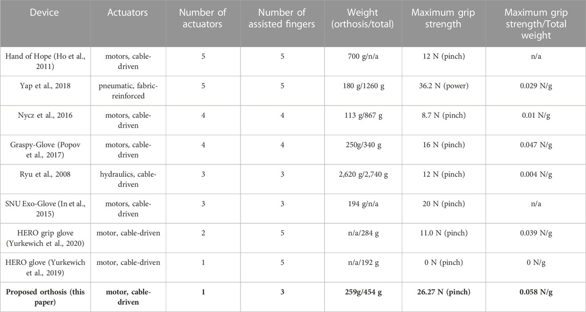
Several portable hand orthoses have been developed by reducing the number of actuators in the soft orthoses for assistive purposes in daily living (In et al., 2015; Polygerinos et al., 2015; Thielbar et al., 2016; Popov et al., 2017; Yap et al., 2018; Yurkewich et al., 2019; 2020). Some portable orthoses (Popov et al., 2017; Yurkewich et al., 2019; 2020) even do not require any long tendon sheaths and tubes for convenient use. Although multiple portable hand orthoses have been developed for stroke survivors, they have not been quantitatively evaluated for their effectiveness at assisting with grasping tasks for ADL due to an issue regarding grip strength. It is because the assistive force of portable hand orthoses is limited by the allowable number, size, and weight of actuators, which inhibits finger extension and grip strength (Yurkewich et al., 2019; 2020). Many researchers have developed portable orthoses of which actuation modules are remotely mounted on the body such as on the waist (Polygerinos et al., 2015; Thielbar et al., 2016; Yap et al., 2018) to reduce the external weight on the hand; however, heavy actuators are still associated with poor usability.
An elastic structure can be used for portable orthoses (Arata et al., 2013; Nycz et al., 2016) to ensure passive finger extension, thus reducing the required number of actuators for grasping assistance. The stiffness of the structure significantly affects grasping performance for each individual; the low stiffness would result in limited grip aperture in the pre-grasping phase by spastic finger joints while the high stiffness would lead to limited grip strength in the grasping phase by requiring unnecessarily high assistive force for flexion. Thus, it is desirable to personalize the spatial stiffness distribution of the structure based on individual degrees of spasticity (Park et al., 2016) to achieve sufficient grip aperture and grip strength with actuators constrained by number, size, and weight. However, there are limited design guidelines to determine the spatial stiffness distribution of hand orthoses for each individual.
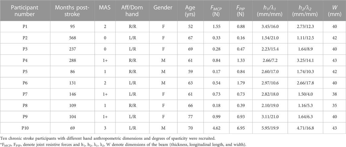
This study presents a personalized spatial stiffness distribution design for a portable and strengthful hand orthosis to assist with grasping tasks (Figure 1). The spatial stiffness distribution is designed as per individuals to achieve a sufficient grip aperture against spasticity in the pre-grasping phase and a minimal assistive force in the grasping phase. Because the degree of spasticity is unique to each stroke survivor, the spatial stiffness distribution is optimized based on measurements of individual hand parameters. The orthosis having the personalized spatial stiffness distribution is made using a 3D printer, and it was evaluated by recruiting chronic stroke survivors with impaired hand functionality. By using only a single small (10
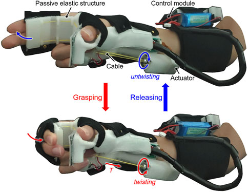
FIGURE 1. The active hand orthosis made by the spatial stiffness distribution design for assisting with grasping tasks during activities of daily living (ADL). The entire orthosis, including the single actuator, was designed to fit compactly on the hand and forearm.
2 Materials and methods
2.1 Overall design
The specifications of the orthosis made by the spatial stiffness distribution design are determined as follows based on the results of previous studies and interviews with clinicians.
1) Portability: The orthosis including the actuators should weigh <500 g (Nycz et al., 2016; Ates et al., 2017; Lambelet et al., 2020) because it will be in constant use throughout the day. Thus, the number of actuators should be minimized.
2) Grasping assistance: The orthosis should assist with the bidirectional movement of the fingers to aid with grasping tasks. The target grip aperture and minimal required grip strength are set to 80 mm (>70 mm (Feix et al., 2014)) and 15 N (Yurkewich et al., 2019), respectively.
3) Comfort and safety: The orthosis should not induce pain, hyperextension, and skin damage during use. The application of a compressive force to finger joints must be avoided when it is assisting with finger movement.
The number of grasp types that the orthosis can assist with is limited because the underactuation of the orthosis is inevitable for portability. Because tripod grasp achieved by three fingers (i.e., the thumb, index finger, and middle finger) was similar with the grasping posture achieved by one of the postural synergies required for a tool use (Santello et al., 1988), it was considered that common objects can be grasped by the tripod grasp. Thus, the tripod grasp is selected for emulation using a single motor.
The orthosis comprises a passive elastic structure (including a beam) fabricated from thermoplastic polyurethane (TPU; Hyvision System, Inc. Seongnam, South Korea), an intention detection module, and a control module (Figure 2A). The orthosis has a total weight of 454 g, and it compactly fits on the affected hand and forearm. The passive elastic structure is made using a 3D printer (Cubicon Single, Hyvision System, Inc. Seongnam, South Korea) and reduces the number of actuators required by realizing the passive extension of fingers. The passive elastic structure allows independent donning/doffing of the orthosis and avoids joint compression during extension of spastic finger joints. The beam of the passive elastic structure where the fingers make contact is designed to optimize the stiffness for ensuring a sufficient grip aperture in the pre-grasping phase and minimizing the required antagonistic assistive force (T) for grasping. The passive elastic structure excluding the beam is designed as per the hand geometry of each user for comfort. Because of finger contracture in the affected hand, a 3D scanner (Sense2, 3D Systems Inc. Rock Hill, SC, United States) is used to scan the unaffected hand when the user grasps an 80-mm-diameter cylinder. The affected hand geometry is generated by mirroring the 3D scanning results assuming symmetry of the hands (Kulaksiz and Gözil, 2002). The thumb module is designed based on the affected hand geometry using the software Geomagic Freeform (3D Systems, Inc. Rock Hill, SC, United States) so that the palmar aspect of the thumb is rigidly fixed at the abducted posture as the user grasps an 80-mm-diameter cylinder.
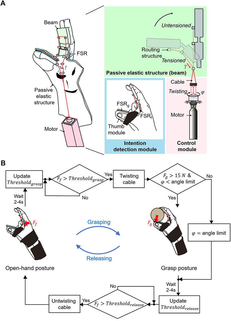
FIGURE 2. Design overview of the active hand orthosis. (A) The orthosis consists of a passive elastic structure for passive extension, a control module for active flexion, and an intention detection module. The rotation angle (
The control module comprises a small motor (10
Because stroke survivors cannot voluntarily extend their fingers because of extensor muscle weakness, the grasping and releasing intentions are detected solely using the FSRf that can measure the flexion force. The grasping and releasing intentions are detected when the FSRf detects a force that exceeds the pre-set values Thresholdgrasp and Thresholdrelease, respectively (Figure 2B). To calculate Thresholdgrasp and Thresholdrelease, the voluntary force of the user is first calculated during voluntary grasping in a setup procedure. The user applies the maximal flexion force for a grasping task while wearing the orthosis. The FSRf measures the peak value for five attempts, and the values are then recorded. The baseline force, which corresponds to the force at rest, is measured before the voluntary grasping. The minimum difference between the peak and baseline forces is defined as the voluntary force. Thresholdgrasp and Thresholdrelease were defined as the sum of the calculated voluntary force and baseline force. These values are updated at the end of every grasping and releasing task because the baseline force varies with spastic contractions over time. At the end of a grasping and releasing task, a waiting period of 2–4 s is implemented until the spastic response settles down, and the force measured after the waiting period is set as the baseline force for the next tasks. The waiting period is determined as per the time required for the force to settle down to 110% of the baseline force that is measured before the voluntary grasping during the setup procedure.
The grasping and releasing tasks are initiated when the user applies a flexion force (Ff) that exceeds the pre-set values (Thresholdgrasp, Thresholdrelease). In the initial state, the fingers are passively extended (open-hand posture) at the initial angle of the motor, which is set when the cable is completely untwisted. Active flexion of the beam is initiated once the user applies a force that exceeds Thresholdgrasp. The active flexion is driven by rotating the motor to twist the cable under a nominal step input current. The motor rotates until the angle limit, which is set to when the end of the beam makes contact with the thumb module. Once the rotation angle reaches the angle limit, a proportional–integral–derivative (PID) controller maintains the angle limit for safety. When the grip strength (Fg) reaches 15 N (Yurkewich et al., 2019) before the motor rotates to the angle limit, the PID controller holds the rotation angle to maintain the holding angle that grasps objects at a 15-N grip strength. The minimally required grip strength of 15 N for grasping (Yurkewich et al., 2019) is used to increase the life cycle of the cable, which can break because of abrasion during twisting. To release an object, the user should flex the fingers to apply a force over Thresholdrelease. Passive extension is achieved by reversely rotating the motor under a nominal input current, which untwists the cable. Once the rotation angle reaches the initial angle, the PID controller holds the initial angle. For false activation (i.e., unintended grasping and releasing) caused by physical perturbation, the user must reapply a force to return their hand to the desired posture.
2.2 Beam design
The beam geometry was designed to satisfy two conditions: it should passively extend the fingers in the pre-grasping phase, and it must be bendable to allow finger flexion under the action of the assistive force in the grasping phase. To achieve these conditions, the geometric constraints of the beam were determined based on the kinematics of the finger movement. The kinematics varies depending on the anthropometric dimensions of an individual hand. The positions of hand landmarks were used as a reference to measure the anthropometric dimensions and determine the geometric constraints on the beam design. The finger joints and following skin creases were selected as hand landmarks (Figure 3A): the palmar digital crease (PDC) and proximal palmar crease (PPC). Note that the PPC is where the proximal phalanx is folded toward the palm to achieve 90° metacarpophalangeal (MCP) flexion. To satisfy the first condition, the beam was designed to cover the proximal and middle phalanges of index and middle fingers (Figure 3B). This design allows the MCP and proximal interphalangeal (PIP) joints to be passively extended while sensory feedback is obtained via the fingertips.
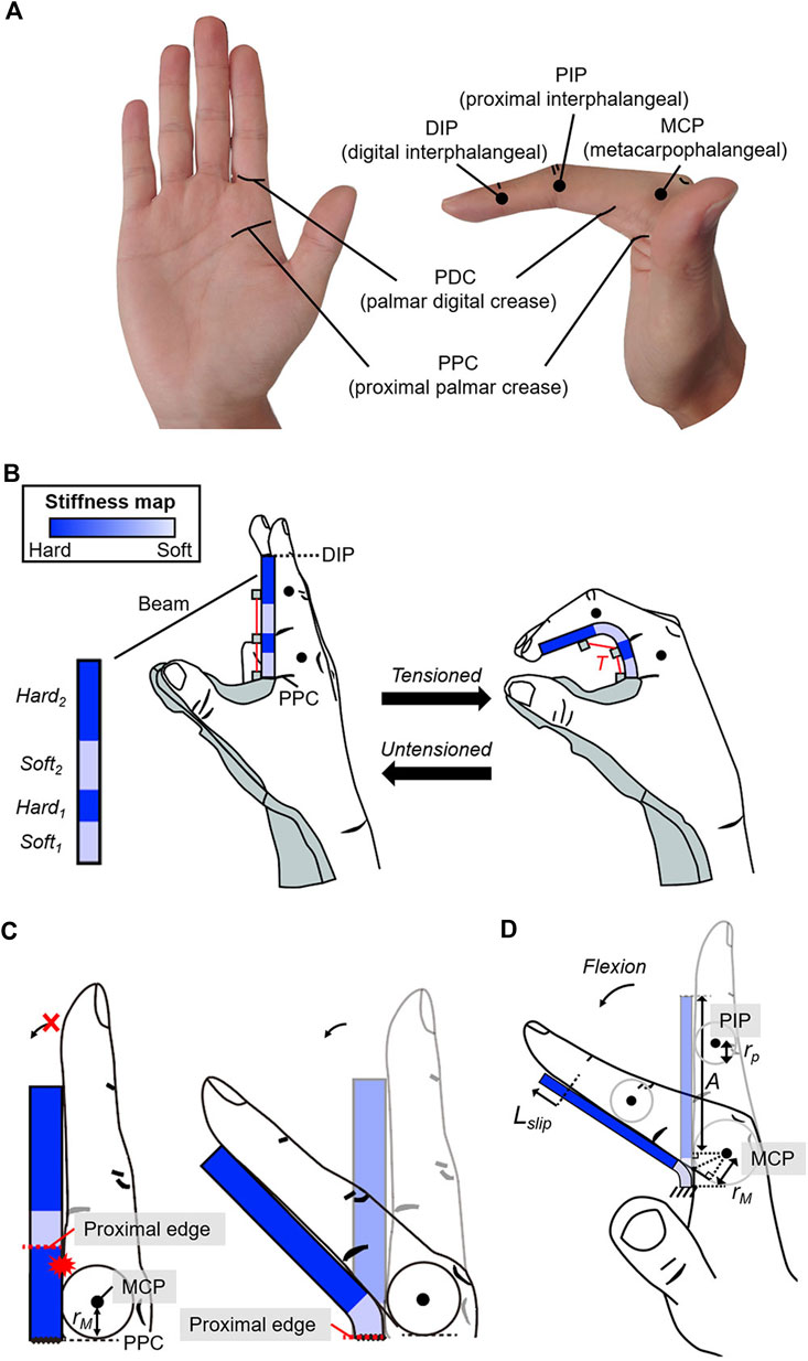
FIGURE 3. Geometric constraints of the beam to enable passive extension and active flexion of the fingers. (A) Hand landmarks used to design the beam. (B) The beam covers the palmar aspect from the PPC to the DIP to enable passive extension of the MCP and PIP joints. The stiffness near the MCP and PIP joints is set lower than that in other regions to allow active flexion of the joints under the assistive force (
To meet the second condition, the stiffness of the beam was designed as follows. Active flexion requires that the beam deflection along the MCP and PIP joints be significantly larger than in other regions; thus, stiffness close to the MCP and PIP joints should be less than that in other regions. The beam comprises two soft regions (Soft1 and Soft2) and two hard regions (Hard1 and Hard2) (Figure 3B). Because the beam is at the palmar aspect of the fingers, the proximal edge of soft regions was constrained to be more proximal than the corresponding joint by at least the radius of the joint to allow finger flexion (Figure 3C). The proximal edge of Soft1 was assigned to the PPC, which is more proximal than the MCP joint by the radius of the MCP joint (rM) for all users. The position of Soft2 was determined by considering the slip occurrence between the beam and fingers during MCP flexion. The beam slips with respect to the fingers (Figure 3D) during MCP flexion. Thus, the proximal edge of Soft2 was set to be more proximal than the PIP joint by a length that is greater than the sum (Lconst2) of the slip distance (Lslip) and radius of the PIP joint (rp). Because 35° of MCP flexion has been reported to occur during tripod grasping (Park et al., 2014), Lconst2 that occurs during MCP flexion was used as a geometric constraint for Soft2, and it can be calculated as follows:
A (Figure 3D) is the length between the distal interphalangeal (DIP) and MCP joints at full extension. rM and rP are the radii of the MCP and PIP joints, respectively. The proximal edge of Soft2 was set to the PDC considered to be more proximal than the PIP joint by length greater than the Lconst2 (An et al., 1983; Buryanov and Kotiuk, 2010). Thus, the determined beam geometry comprises two soft regions (Soft1 and Soft2) and two hard regions (Hard1 and Hard2) at predefined locations to allow bidirectional finger movement.
The stiffness can be adjusted by changing the thickness along the beam (Figure 4). The stiffness of Soft1 and Soft2 is determined by design variables (
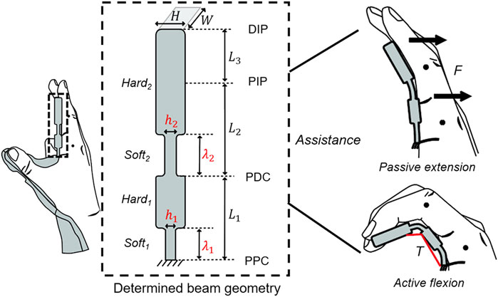
FIGURE 4. Determined beam geometry consisting of two soft regions (Soft1 and Soft2) and hard regions (Hard1 and Hard2) under the geometric constraints. The stiffness of the soft regions is determined by the design variables (
2.3 Stiffness optimization
There exists a tradeoff between an achievable grip aperture and grip strength because an increase in the spatial stiffness leads to an increase in the grip aperture and required assistive force for grasping. The stiffness optimization enables the orthosis to achieve a target grip aperture in the pre-grasping phase while minimizing the required assistive force in the grasping phase. It would enable the orthosis to grasp common objects with increased grip strength by a given small-sized motor. Because stroke survivors have different joint characteristics (Kim et al., 2019) such as degree of spasticity, the stiffness should be optimized as per the measurements of individual hand parameters. Otherwise, the spatial stiffness distribution that is equally designed for all stroke survivors may result in a limited grip aperture for users with a severe degree of spasticity and or require an unnecessarily large amount of assistive force for users with flaccid hands. The stiffness optimization process has two steps: obtaining stiffness solutions that can achieve the target grip aperture and identifying the optimal solution that requires a minimal assistive force.
2.3.1 Stiffness solutions for passive extension
Before determining the stiffness of Soft1 and Soft2, the relevant individual hand parameters should be measured. The anthropometric dimensions of the hand are the primary parameters. In this study, the dimensions were measured using a goniometer (Model 12-1012, Baseline®, Fabrication Enterprises, Inc. NY, United States), and they are used to determine L1, L2, L3, W, and H of the beam. Because finger contracture made it difficult to measure the affected hand, the dimensions were measured for the unaffected hand assuming the symmetry of both hands (Kulaksiz and Gözil, 2002). The joint angles that yield the target grip aperture of 80-mm (ϕMCP and ϕPIP) are the secondary parameters. The target joint angles that should be maintained are used to determine the stiffness of Soft1 and Soft2. Because the joint angles differ among individuals because of the dissimilar hand size, the joint angles should be measured for each user and then be used to set constraints in determining the stiffness of Soft1 and Soft2. The joint angles were measured using the goniometer as a user grasps an 80-mm-diameter cylinder with their unaffected hand. The force applied to the beam by the fingers (i.e., joint resistive force) deflects Soft1 and Soft2 and decreases the grip aperture. This joint resistive force should be known to determine the necessary stiffness for Soft1 and Soft2 to achieve passive extension. Thus, the joint resistive force is the tertiary parameter. Because the joint resistive force differs depending on the degree of spasticity, it should be measured for each user.
Before measuring the force, the location where the force is applied was obtained by static analysis under the condition that the finger and beam contact each other. In this study, finite element analysis (FEA) was used using ABAQUS (6.14, Dassault Systèmes Simulia Corp. Providence, RI, United States) for static analysis. An individual hand–beam model was developed (Figure 5A) that uses the measured dimensions of the index finger and position of the center of the joint rotation. The kinematics of the middle finger was assumed the same as that of the index finger for simplicity. The beam comprises two soft regions and two hard regions as per geometric constraints. Three longitudinal lengths (i.e., min, mid, and max) were used for each soft region of the beam. Because there is no thickness information for the beam, a constant thickness that satisfies the aspect ratio criterion was used for the entire beam. The hard regions were modeled to be rigid by applying kinematic constraints. A dynamic flexural modulus of 46.49 MPa was applied to the beam; this value was measured for TPU by operating a three-point bending test system (DTS Company, Menlo Park, CA, United States) at a strain rate of 0.1/s. The TPU was modeled as an elastic material because the TPU showed a linear stress-strain curve at low strain regions occurred during the active flexion. The modeled finger was flexed based on the individually measured joint angles, and it was found that the contact pressure is concentrated near the PDC and DIP joint (i.e., primary contact areas). Thus, the joint resistive forces were assumed to concentrate at positions of the PDC and DIP joint.
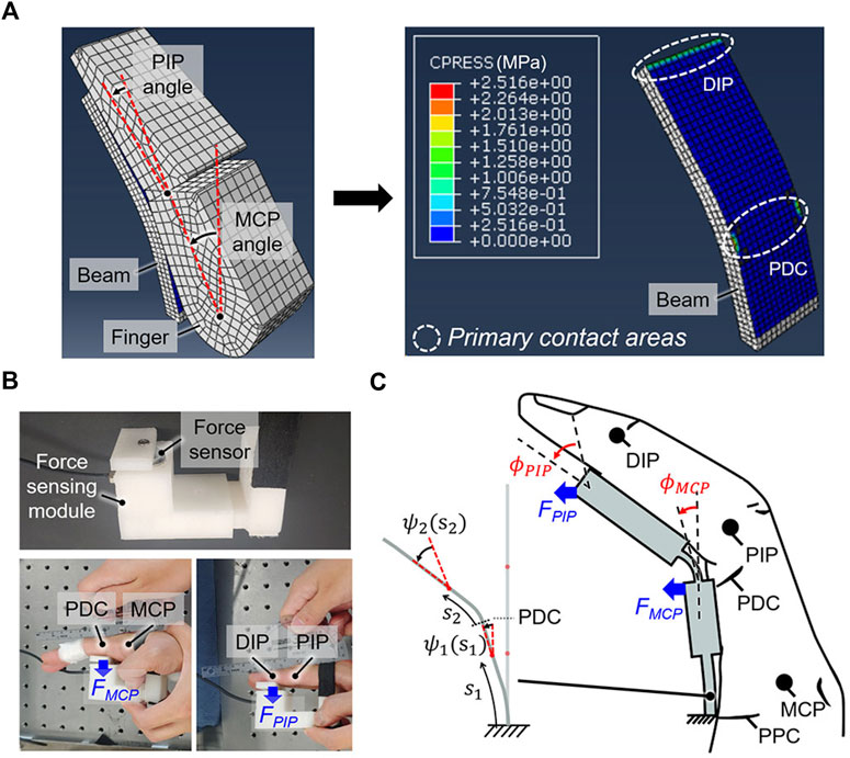
FIGURE 5. Obtaining the stiffness solutions of the beam to achieve passive extension. (A) The contact pressure is concentrated at the primary contact areas, which are located near the PDC and DIP when the finger is flexed against the beam to achieve a target grip aperture of 80 mm. (B) The joint resistive forces (FMCP, FPIP) at the primary contact areas, which are respectively applied to extend the MCP and PIP joints, were measured using a force sensor. (C) Calculating the stiffness solutions for which the beam deflection angles (ψ1, ψ2) at the primary contact areas equal the individually measured joint angles (
The joint resistive forces (FMCP and FPIP) for the user were measured based on the positions of primary contact areas (Figure 5B). In this study, a force-sensing module containing a force sensor (KTOYO 247SA, KTOYO, Ltd. Uijeongbu, South Korea) was used for measurements. The user sits in a chair that is adjusted such that the base of the sternum is approximately parallel to the tabletop. The user then rests their affected arm on the table and extends the elbow as much as possible. The wrist is externally maintained in a neutral posture by the experimenter, and a force sensor at the position of the PDC (i.e., primary contact area) of the index finger to maintain fully extended MCP joint is used to measure FMCP. The PIP joints are taped to prevent fingertips from touching the force-sensing module. A force sensor at the position of the DIP joint (i.e., primary contact area) of the index finger to maintain fully extended PIP joint is used to measure FPIP. For this measurement, the experimenter externally holds the MCP joints in full extension. During the measurement, the force was nearly constant when the spastic response occurred right after the extension settled down. To eliminate the contribution of the spastic response immediately after movement, the force was measured for 1 min, and the average force over the last 10 s is considered as FMCP or FPIP.
The measured hand parameters are used to obtain the stiffness of Soft1 and Soft2 such that the beam can maintain the required joint angles against the joint resistive forces. The beam can be divided into two segments as per the position of the PDC. Thereafter, h1 and h2 were calculated with respect to λ1 and λ2 as follows, respectively (Beléndez et al., 2005):
where ψ1 (s1) and ψ2 (s2) are the beam deflection angles at s1 and s2, which are the arc lengths between the fixed end and a point on the corresponding segment (Figure 5C). h (s1) and h (s2) are the thickness at s1 and s2. M1, M2, and E are the corresponding bending moments and Young’s modulus. The beam stiffness should be set to ensure a grip aperture of 80 mm. The difference between the beam deflection angles and joint angles at the primary contact areas is < 2.95° on average (Figure 5A). Thus, the boundary conditions (B.C1 and B.C2) were set to make the beam deflection angles at the primary contact areas equal to the individually measured joint angles (ϕMCP and ϕPIP). Hard1 and Hard2 were assumed to be sufficiently stiff to ensure that any changes in ψ1 (s1) and ψ2 (s2) are negligible. In this study, MATLAB (2018a, MathWorks Inc. Natick, MA, United States) was used to calculate h1 and h2 based on λ1 and λ2, which are pre-set to change in increments of 1 mm within the geometric constraints. Then, stiffness solutions that satisfy Eq. 2 can be obtained.
The Young’s modulus of TPU was measured under the condition of a quasi-static strain rate (0.0021/s) using a high-precision micromechanical test system (DTS Co., Menlo Park, CA, United States). This measured Young’s modulus (22.35 MPa) was used as E in Eq. 2 and associated with the target deflection required to maintain a grip aperture of 80 mm. In particular, the beam deflection was designed such that it would approach the target deflection over time because of creep. The creep-induced beam deflection was considered to ensure that the grip aperture asymptotically converged to 80 mm during the wearing period.
The spasticity of the flexor muscles can change over time and made it difficult to guarantee that the beam, which has fixed spatial stiffness distribution, would maintain the target grip aperture. A grip aperture less than the target of 80 mm would present a challenge in positioning common objects within the hand for grasping in the pre-grasping phase. Thus, a safety factor was applied to the degree of spatial stiffness; the spatial stiffness distribution was designed to achieve the target grip aperture against maximal joint resistive forces. The joint resistive forces are greatest when the fingers are fully extended. Thus, the maximal joint resistive forces statically measured at the fully extended posture (FMCP and FPIP) were used in Eq. 2 to find the stiffness solutions.
2.3.2 Optimizing the stiffness for active flexion
To identify the optimal solution that requires a minimal assistive force for active flexion among the stiffness solutions, the amount of beam deflection required to emulate the tripod grasp (i.e., target grasp type) should be determined first. The ROMs of finger joints during a tripod grasp were used to determine the required beam deflection. The ROMs were measured during tripod grasping tasks using the unaffected hand (Figure 6A). In this study, the average results from three trials were recorded. Reflective markers were placed atop the fingertip, metacarpal, MCP, PIP, and DIP joints of the index finger to enable motion analysis with a motion capture system (OptiTrack V120: Trio, NaturalPoint, Inc. Corvallis, OR, United States). Principal component analysis was then applied to the 3D trajectory data of the reflective markers to identify the planes of flexion/extension movements. The 3D trajectory data was projected on the plane of flexion/extension, and the joint angles were calculated based on the projected trajectory data for relieving the influence of the abduction/adduction movement (Randazzo et al., 2017). Because the determined beam geometry allows finger flexion under beam deflection, the target beam deflection angles at hard regions were assumed the measured ROMs for assisting fingers with tripod grasping.
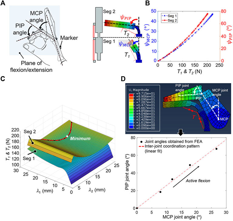
FIGURE 6. Finding the optimal solution among stiffness solutions that minimizes the assistive force for active flexion. (A) The MCP and PIP joint ROMs of the unaffected hand during tripod grasping were measured by capturing the 3D trajectories of the reflective markers. (B) The relationship between the assistive force (
In this study, FEA was used to simulate the active flexion of stiffness solutions to obtain the relationship between beam deflection angles (
The measured ROMs and relationships were used to determine the optimal solution that achieves the tripod grasp with the minimal assistive force. The ROM measurement results for the MCP and PIP joints were set as the targeted beam deflection angles of each segment for calculating T1 and T2. In particular, T1 and T2 that yield
The finger joint angles during active flexion were obtained using an individual hand–beam model. For the model, the optimal solution was used for the beam, and measured dimensions were used for the hand (Figure 6D). The beam was deflected under the assistive force (T), and finger joint angles when the finger makes contact with the beam were calculated. It was confirmed that the PIP joint angle increased linearly with respect to the MCP joint angle, and this inter-joint coordination pattern of the joint angles was obtained to check whether finger joint angles of users increase in accordance with the obtained inter-joint coordination pattern during assistance.
2.4 Experimental evaluation
2.4.1 Participant recruitment
Ten stroke survivors having varying degrees of spasticity were recruited (Table 1) to evaluate the performance of the proposed orthosis at assisting with grasping tasks. The recruited participants were in the chronic stage with limited voluntary ROM. They could follow instructions and had no severe risk of skin breakdown for safety. The participants who scored a MAS grade of four were excluded because passive movement is physically difficult. Moreover, the participants with botulinum toxin type A injection were excluded because the injection can affect the degree of spasticity. The orthosis was personalized as per individuals and 3D-printed. Because the required assistive force for grasping increases as the stiffness of the orthosis increases, the motor that can actively flex the orthosis having the highest stiffness was selected and used for all orthoses to ease the design. The research was approved by the Institutional Review Board of KAIST (KH2020-59, 04/07/2020), and written consent was obtained from each participant after the experiment was explained.
2.4.2 Evaluation criteria
The following criteria were used to evaluate the performance of the proposed orthosis design.
1) Beam deflection and grip aperture: The beam deflection was measured to confirm whether it was equal to the target deflection. The target deflection was obtained using FEA by applying the maximal joint resistive force to the beam having the measured Young’s modulus. The increase in the deflection of the distal end of the beam was used (Figure 7A) to determine whether the beam is deflected closed to the target deflection to yield the target grip aperture. It was measured immediately after being donned by tracking five reflective markers that were positioned along the upward-facing side of the beam. Because it has been reported that no significant plastic deformation occurs after four cycles of active flexion (Qi and Boyce, 2005), the beam deflection was measured again after four repetitions of active flexion. The grip aperture was measured based on markers attached to the index fingertip and thumb tip to verify whether it achieved the target grip aperture of 80 mm.
2) ROM measurement: The ROMs for the MCP and PIP joints of the index finger were measured before and after the orthosis was applied to the affected hand. Reflective markers were placed atop the metacarpal, MCP, PIP, and DIP joints and the fingertip of the index finger for tracking, and joint angles were obtained based on the 3D trajectory data of the markers. The voluntary ROM (i.e.,
where
3) Grasp performance: The maximum grip strength with the orthosis, in addition to the ability of the orthosis to grasp various objects, were evaluated. The objects applied for this test were selected based on the previous study (Kang et al., 2016), and they were as follows: a glass cup, baseball, stapler, golf ball, banana, and rectangular battery. The maximum grip strength was measured at the angle limit of the motor when the participant grasped a rectangular 40-mm-height (i.e., 50% of the target grip aperture) grip strength–sensing module without any voluntary force. For this measurement, the motor was rotated until the angle limit regardless of the grip strength measured by the FSR sensor. The force sensor (KTOYO 247SA, KTOYO, Ltd. Uijeongbu, South Korea) was embedded in the grip strength–sensing module (Figure 7B).
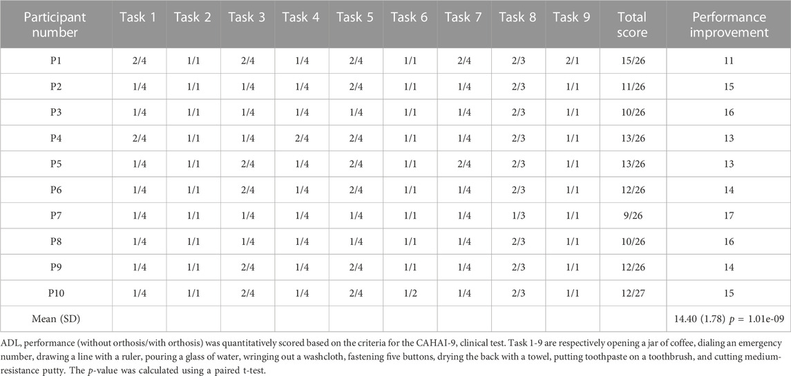
4) Functional assessment and questionnaire: Each participant was instructed to perform nine ADL tasks from the Chedoke Arm and Hand Activity Inventory (CAHAI)-9 (Barreca et al., 2004) to evaluate the assistive performance of the orthosis with grasping tasks. All nine tasks were bimanual activities: 1) opening a jar of coffee, 2) dialing an emergency number, 3) drawing a line with a ruler, 4) pouring a glass of water, 5) wringing out a washcloth, 6) fastening five buttons, 7) drying the back with a towel, 8) putting toothpaste on a toothbrush, and 9) cutting medium-resistance putty. The performance of each ADL task was evaluated on a scale of 1–7 by the experimenter according to the CAHAI-9 criteria (Jane Rowland et al., 2011). Both hands were positioned on the table, and the participants were instructed to refrain from placing their elbows on the table. Because the participants lacked fine control of the affected arm, it was supported by a gravity compensator and experimenter. The participants first performed all nine tasks without the orthosis. After a 5 min break, they repeated tasks with the orthosis under the same environmental conditions. The performance improvement was quantitatively evaluated by comparing the scores with and without the orthosis. After conducting the functional assessment, the participants were asked to answer a questionnaire comprising 1) the weight of the orthosis is manageable, 2) the assistance of the orthosis is satisfactory, and 3) the orthosis is comfortable while using. The questions were determined based on the orthotics and prosthetics user’s survey (OPUS) (Heinemann et al., 2003). The satisfaction of the participants was ranked from one to five, in which the value increases with higher satisfaction.
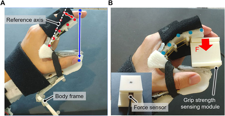
FIGURE 7. Experimental setup for evaluating the orthosis. (A) The beam deflection at the tip (red arrow) and grip aperture (blue arrow) were measured by tracking reflective markers, which were attached to the upward-facing side of the beam (red dot) and fingertips (blue dot). The beam deflection was measured with respect to the reference axis, which was determined based on the markers prior to the orthosis being worn. (B) The grip strength of the orthosis was measured using a grip strength–sensing module under an applied assistive force.
3 Results
3.1 Beam deflection and grip aperture
The beam deflection was less than the target deflection, thereby yielding a grip aperture larger than the target grip aperture of 80 mm. The distal end of the beam deflected by 12.17 ± 10.00 mm immediately after donning, generating the grip aperture of 94.26 ± 10.73 mm. This measured deflection was less than the target deflection of 40.08 ± 7.37 mm primarily owing to viscosity of the TPU. Because of creep occurred after donning and plastic deformation by active flexion, the beam deflection increased by 9.38 ± 5.48 mm after four repetitions of active flexion, which corresponded to an average decrease of 6.74 mm for the grip aperture. Non-etheless, the measured beam deflection of 21.54 ± 9.36 mm still did not equal to the target deflection of 40.08 ± 7.37 mm, yielding a grip aperture of 87.52 ± 6.40 mm. The error for the beam deflection would be because of the safety factor considered in designing the stiffness of the beam. The beam stiffness was set to yield the target grip aperture against the maximal joint resistive force; however, fingers would apply force less than the maximal joint resistive force on the beam. This would primarily make the measured deflection be less than the target deflection, which led to increase in the grip aperture.
3.2 ROM measurement
The orthosis effectively assisted the finger joints for all participants (Figures 8A, B). All participants demonstrated a limited voluntary ROM of 20.7° on an average because of spastic finger joints. They were only able to flex their fingers from a neutral posture to a closed-hand posture. Although the orthosis-enabled finger flexion was limited by the thumb module, the orthosis increased the joint ROM by 31.7° ± 26.6°. Note that the finger flexion was not restricted by the thumb when the voluntary ROM was measured. The ROMs of the MCP and PIP joints were increased by 9.0° ± 12.1° and 22.8° ± 18.2°, respectively. Moreover, the orthosis provided passive assistance to yield a maximal assisted extension angle of 33.2° ± 12.0°; the fingers were significantly more extended compared to the maximal voluntary extension (maximal unassisted extension angle of 118.2° ± 25.8°).
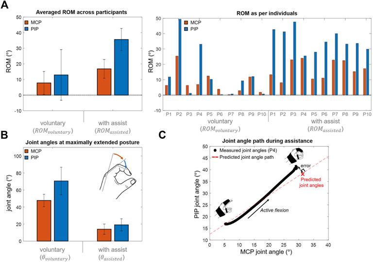
FIGURE 8. Experimental results. (A) Averaged ROM across participants during voluntary and assisted flexions (mean difference of MCP and PIP joint ROMs = 9.0
The finger joint angles increase in accordance with the inter-joint coordination pattern obtained by the individual hand–beam model. The “Measured joint angles” in Figure 8C was obtained based on the measurement results during active flexion. The “Predicted joint angle path” in Figure 8C was obtained by increasing joint angles from the maximal assisted extension posture according to the inter-joint coordination pattern. It was confirmed that the joint angles increase in accordance with the inter-joint coordination pattern. The error between the joint angles at maximal flexed posture and predicted joint angles were 4.9° ± 2.9° which were respectively 4.3° ± 2.6° in the MCP joint and 2.2° ± 1.4° in the PIP joint. The joint resistive force was not considered in the hand-beam model to obtain the inter-joint coordination pattern, and it would result in the error which was only 9.3% of assisted joint ROM on average. The inter-joint coordination of the MCP and PIP joints during assistance can be controlled by spatial stiffness distribution design.
3.3 Grasp performance
All participants could grasp each object with the orthosis. Furthermore, they were able to establish contact between their fingertips and large-size objects (i.e., the glass cup and baseball). However, the large slip between the fingers and beam prevented the fingertips from contacting the small-size objects (i.e., banana, stapler, golf ball, and battery). The maximum grip strength was measured as 26.27 ± 3.90 N, and the orthosis showed a high grip strength-to-weight ratio (Table 2).
3.4 Functional assessment and questionnaire
The results of the CAHAI-9 tasks (Table 3) demonstrated that all participants had difficulty without the orthosis owing to contracture and low grip strength. The score of one or two was assigned for all tasks because participants do not voluntarily show any manipulation of the affected hand. With orthosis, all participants were able to complete the tasks except for tasks 2, 6, and 9 with only arm support and cueing (Figure 9). The orthosis increased the grip aperture and grip strength of participants to improve their performance of most tasks (score increase: 14.40 ± 1.78). To precisely locate targeted objects along the beam for grasping, the unaffected hand was used for positioning because the orthosis cannot assist with in-hand and upper-limb manipulations. Non-etheless, with only the passive assistance of the arm, the orthosis enabled the participants to independently accomplish bimanual tasks by stably holding targeted objects with the affected hand. Specifically, for task 1, they could open a lid of the jar using the unaffected hand because the affected hand could hold a jar. For task 3, they could draw a line by grasping a pen with the affected hand while the unaffected hand is fixing the ruler. For task 4, participants held a glass cup using the affected hand while pouring water with the unaffected hand. For task 5, one side of a washcloth was held by the affected hand, and the unaffected hand wrung out a wash cloth. For task 7, one side of a towel was held by the affected hand, and the unaffected hand dried the back with a towel. Thus, stroke survivors were assigned score of four for these tasks because they can accomplish 100% of tasks with arm support. For task 8, although it was possible to hold a toothpaste using the affected hand to make the unaffected hand unscrew a lid, squeezing the toothpaste using only the affected hand was impossible with the control algorithm used for the orthosis. Thus, a score of three was assigned for task eight by considering that 50% of the task is accomplished. The orthosis could not provide adequate assistance in tasks 6 and 9 because the tripod grasp type was insufficient to manipulate the object. Task two was not completed because the participants were unable to prevent their ring and little fingers from pushing non-targeted buttons.
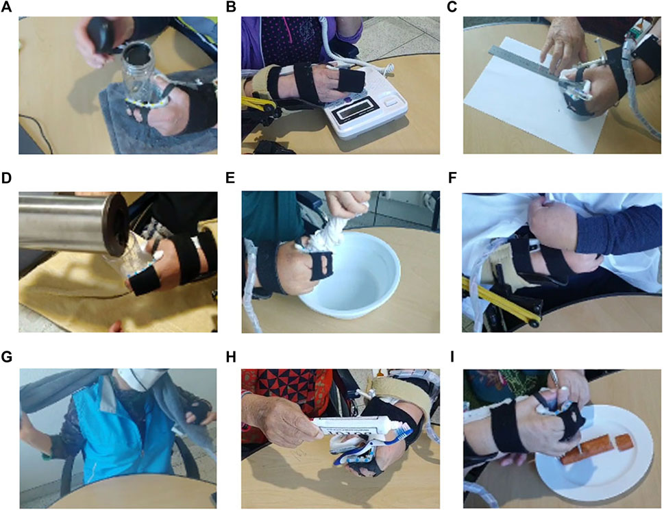
FIGURE 9. Tasks 1–9 from the Chedoke Arm Hand Activity Inventory (CAHAI)-9. (A) Task 1: Opening a jar of coffee. (B) Task 2: Dialing an emergency number. (C) Task 3: Drawing a line with a ruler. (D) Task 4: Pouring a glass of water. (E) Task 5: Wringing out a washcloth. (F) Task 6: fastening five buttons, (G) Task 7: Drying the back with a towel. (H) Task 8: Putting toothpaste on a toothbrush. (I) Task 9: Cutting medium-resistance putty.
The participants answered that the device is sufficiently lightweight (score: 4.3 ± 0.7) and comfortable (score: 4.2 ± 0.5). Moreover, they were satisfied with the assistance of the orthosis (score: 4.3 ± 0.48).
4 Discussion
In this study, a personalized spatial stiffness distribution is presented for a portable and strengthful hand orthosis. The stiffness was optimized for each participant based on measurement of individual hand parameter to satisfy predetermined requirements for the orthosis: maintaining a minimum grip aperture of 80 mm and minimizing the assistive force needed to achieve flexion. The stiffness optimization of the passive elastic structure assists individuals with finger flexor spasticity to achieve the target grip aperture to grasp common objects while minimizing the antagonistic assistive force to generate sufficient grip strength. The experimental results demonstrated that the orthosis achieves a high grip strength-to-weight ratio and weighs only 454 g, including all of the motor, electronics, and battery located at the hand and forearm. It was demonstrated that the strengthful all-in-one orthosis achieved by the spatial stiffness distribution design can assist participants with the bidirectional movement of the affected hand to grasp various objects and thus can aid with bimanual tasks for ADL.
The passive elastic structure enabled spastic finger joints to be extended even for a participant who has MAS grade of three. Previous orthoses (Lee et al., 2014; Nycz et al., 2016; Popov et al., 2017; Kim and Park, 2018; Yurkewich et al., 2020) assist with extension using cables as exotendons. However, for stroke survivors with a severe degree of spasticity, the tension applied by exotendons to assist with extension may apply a relatively large compressive force on the finger joints, which is a safety concern (Felson, 2013; Kim et al., 2019). The proposed orthosis includes a passive elastic structure that is positioned on the palmar aspect of the affected hand to eliminate the requirement for exotendons and increase the moment arms of the extending forces applied at finger joints. Participants replied that they did not feel any pain and discomfort during assisted finger joint extension. The passive elastic structure would enabled the orthosis to assist finger extension against spastic finger joints with reduced joint compression.
The spatial stiffness distribution design of the orthosis significantly affects ROMs of finger joints during assistance. In this study, by adjusting the stiffness along the beam considering the slip between the fingers and beam, the limited increase in ROM during assistance is avoided. In particular, the hard region of beam can limit the ROM of the PIP joint when the slip during finger flexion is not considered in the spatial stiffness distribution design. The soft regions were respectively positioned close to the finger joints considering the slip, and their stiffness were adjusted to emulate the tripod grasp. The proposed design prevents the beam from blocking finger flexion and enables users to conduct tripod grasp. The proposed orthosis was demonstrated to increase the ROM of finger joints by an average of 31.7°, which is similar to that of a previous orthosis (i.e., 46.3°) (Yurkewich et al., 2019).
The results highlight the importance of a user-specific orthosis design. To maximize user compliance and increase grip strength through reduced actuator size and weight, orthosis was personalized for each participant based on the measurements of hand parameters. This was achieved by first considering the individual hand geometry. With the exception of the beam component, the passive elastic structure was designed based on the affected hand geometry generated by 3D scanning. All participants reported that the orthosis was comfortable. The second individualized characteristic that was considered was the joint resistive force, particularly for MCP and PIP joints. The spatial stiffness distribution was personalized based on measurement results of joint resistive force to ensure sufficient grip aperture and high enough grip strength, and it was shown that the orthosis can achieve grasping assistance with a high grip strength-to-weight ratio. The required motor size and weight for grasping assistance would be reduced by considering individual joint characteristics in the spatial stiffness distribution design.
The TSA mechanism was selected to improve the portability of the orthosis using its high contraction force-to-torque ratio and mechanical simplicity. Owing to its characteristics, the actuating module adopting the TSA mechanism becomes compact in comparison with the other actuating modules such as soft fluidic actuators (Zhang et al., 2019). However, the TSA mechanism has the disadvantage of contraction length. It can maximally generate contraction length as 30% of its untwisted length, and this should be considered in hardware design. In this study, the motor was mounted at the forearm to provide the untwisted length required for generating contraction length to flex the orthosis.
The proposed orthosis does have limitations. First, the cable of the TSA mechanism can break during use. The cable breaks after being twisted several times (Palli et al., 2013), which may decrease the usability. Devising an easily replaceable cable module may solve this limitation. Second, the orthosis was unable to assist with two tasks from CAHAI-9 (i.e., cutting medium-resistance putty and fastening five buttons). This is because the single tripod grasp was insufficient to perform these tasks. In particular, the limited degrees of freedom of the orthosis ultimately hindered manipulation of the objects, which prevented it from assisting the participants with tasks requiring dexterous manipulation. For the putty-cutting task, the applied torque caused the fork to rotate when the participant attempted to pierce the putty. For button fastening, dexterous manipulation was required to pull holes in the cloth toward the buttons.
In this study, a personalized spatial stiffness distribution design is presented for a portable and strengthful hand orthosis to assist with grasping tasks. The objective was to design spatial stiffness distribution that can assist bidirectional finger movement with a sufficient grip aperture in the pre-grasping phase and high enough grip strength in the grasping phase. The orthosis includes a passive elastic structure with an individually optimized stiffness and a cable contracted by TSA mechanism using a single motor. In the experiment, the orthosis can assist with grasping tasks for ADL by providing a sufficient grip aperture and grip strength. The orthosis increased the grip aperture and grip strength of all participants, enabling successful grasping even by those with severe degrees of spasticity.
Data availability statement
The raw data supporting the conclusions of this article will be made available by the authors, without undue reservation.
Ethics statement
The studies involving human participants were reviewed and approved by Institutional Review Board, Korea Advanced Institute of Science and Technology. The patients/participants provided their written informed consent to participate in this study. Written informed consent was obtained from the individual(s) for the publication of any potentially identifiable images or data included in this article.
Author contributions
All authors listed have made a substantial, direct, and intellectual contribution to the work and approved it for publication.
Funding
This work was supported by the National Research Foundation of Korea (NRF) grant funded by the Korea government (MSIT) (No. NRF-2020R1A2C2012641).
Conflict of interest
The authors declare that the research was conducted in the absence of any commercial or financial relationships that could be construed as a potential conflict of interest.
Publisher’s note
All claims expressed in this article are solely those of the authors and do not necessarily represent those of their affiliated organizations, or those of the publisher, the editors and the reviewers. Any product that may be evaluated in this article, or claim that may be made by its manufacturer, is not guaranteed or endorsed by the publisher.
Supplementary material
The Supplementary Material for this article can be found online at: https://www.frontiersin.org/articles/10.3389/fbioe.2023.895745/full#supplementary-material
References
Aiple, M., and Schiele, A. (2013). Pushing the limits of the CyberGrasp™ for haptic rendering. Proc. IEEE ICRA 2013, 3541–3546. doi:10.1109/ICRA.2013.6631073
Alicea, R., Xiloyannis, M., Chiaradia, D., Barsotti, M., Frisoli, A., and Masia, L. (2021). A soft, synergy-based robotic glove for grasping assistance. Wearable Technol. 2, e4. doi:10.1017/wtc.2021.3
An, K.-N., Ueba, Y., Chao, E., Cooney, W., and Linscheid, R. (1983). Tendon excursion and moment arm of index finger muscles. J. biomechanics 16, 419–425. doi:10.1016/0021-9290(83)90074-X
Arata, J., Ohmoto, K., Gassert, R., Lambercy, O., Fujimoto, H., and Wada, I. (2013). A new hand exoskeleton device for rehabilitation using a three-layered sliding spring mechanism. Proc. IEEE ICRA 2013, 3902–3907. doi:10.1109/ICRA.2013.6631126
Ates, S., Haarman, C. J., and Stienen, A. H. (2017). SCRIPT passive orthosis: Design of interactive hand and wrist exoskeleton for rehabilitation at home after stroke. Auton. Robots 41, 711–723. doi:10.1007/s10514-016-9589-6
Ates, S., Mora-Morenzo, I., Wessels, M., and Stienen, A. H. (2015). Combined active wrist and hand orthosis for home use: Lessons learned. Proc. ICORR 2015, 398–403. doi:10.1109/ICORR.2015.7281232
Barreca, S., Gowland, C. K., Stratford, P., Huijbregts, M., Griffiths, J., Torresin, W., et al. (2004). Development of the Chedoke arm and hand activity inventory: Theoretical constructs, item generation, and selection. Top. Stroke Rehabil. 11, 31–42. doi:10.1310/JU8P-UVK6-68VW-CF3W
Bayona, N. A., Bitensky, J., Salter, K., and Teasell, R. (2005). The role of task-specific training in rehabilitation therapies. Top. Stroke Rehabil. 12, 58–65. doi:10.1310/BQM5-6YGB-MVJ5-WVCR
Beléndez, T., Pérez-Polo, M., Neipp, C., and Beléndez, A. (2005). Numerical and experimental analysis of large deflections of cantilever beams under a combined load. Phys. Scr. 2005, 61. doi:10.1238/Physica.Topical.118a00061
Borboni, A., Mor, M., and Faglia, R. (2016). Gloreha—Hand robotic rehabilitation: Design, mechanical model, and experiments. J. Dyn. Syst. Meas. Control 138, 111003–111015. doi:10.1115/1.4033831
Burns, M. K., and Vinjamuri, R. (2020). “Design of a soft glove-based robotic hand exoskeleton with embedded synergies,” in Advances in motor neuroprostheses (Springer), 71–87. doi:10.1007/978-3-030-38740-2_5
Buryanov, A., and Kotiuk, V. (2010). Proportions of hand segments. Int. J. Morphol. 28, 755–758. doi:10.4067/S0717-95022010000300015
Cappello, L., Meyer, J. T., Galloway, K. C., Peisner, J. D., Granberry, R., Wagner, D. A., et al. (2018). Assisting hand function after spinal cord injury with a fabric-based soft robotic glove. J. neuroengineering rehabilitation 15, 59–10. doi:10.1186/s12984-018-0391-x
Chae, J., Yang, G., Park, B. K., and Labatia, I. (2002). Muscle weakness and cocontraction in upper limb hemiparesis: Relationship to motor impairment and physical disability. Neurorehabil. Neural Repair 16, 241–248. doi:10.1177/154596830201600303
Chiri, A., Giovacchini, F., Vitiello, N., Cattin, E., Roccella, S., Vecchi, F., et al. (2009). Handexos: Towards an exoskeleton device for the rehabilitation of the hand. Proc. IEEE IROS 2009, 1106–1111. doi:10.1109/IROS.2009.5354376
Dobkin, B. H. (2005). Rehabilitation after stroke. N. Engl. J. Med. 352, 1677–1684. doi:10.1056/NEJMcp043511
Feix, T., Bullock, I. M., and Dollar, A. M. (2014). Analysis of human grasping behavior: Object characteristics and grasp type. IEEE Trans. Haptics 7, 311–323. doi:10.1109/TOH.2014.2326871
Felson, D. T. (2013). Osteoarthritis as a disease of mechanics. Osteoarthr. Cartil. 21, 10–15. doi:10.1016/j.joca.2012.09.012
Heinemann, A. W., Bode, R., and O'reilly, C. (2003). Development and measurement properties of the orthotics and prosthetics users’ survey (OPUS): A comprehensive set of clinical outcome instruments. Prosthet. Orthot. Int. 27, 191–206. doi:10.1080/03093640308726682
Ho, N., Tong, K., Hu, X., Fung, K., Wei, X., Rong, W., et al. (2011). An EMG-driven exoskeleton hand robotic training device on chronic stroke subjects: Task training system for stroke rehabilitation. Proc. IEEE ICORR 2011, 5975340. doi:10.1109/ICORR.2011.5975340
Hoffmann, G., Conrad, M. O., Qiu, D., and Kamper, D. G. (2016). Contributions of voluntary activation deficits to hand weakness after stroke. Top. Stroke Rehabil. 23, 384–392. doi:10.1179/1945511915y.0000000023
In, H., Kang, B. B., Sin, M., and Cho, K. -J. (2015). Exo-glove: A wearable robot for the hand with a soft tendon routing system. EEE Robotics & Automation Magazine 22, 97–105. doi:10.1109/MRA.2014.2362863
Jane Rowland, T., Turpin, M., Gustafsson, L., David Henderson, R., and James Read, S. (2011). Chedoke arm and hand activity inventory-9 (CAHAI-9): Perceived clinical utility within 14 days of stroke. Top. stroke rehabilitation 18, 382–393. doi:10.1310/tsr1804-382
Kamper, D. G., Fischer, H. C., Cruz, E. G., and Rymer, W. Z. (2006). Weakness is the primary contributor to finger impairment in chronic stroke. Arch. Phys. Med. Rehabil. 87, 1262–1269. doi:10.1016/j.apmr.2006.05.013
Kang, B. B., Lee, H. H., Jeong, U., Chung, J., and Cho, K.-J. (2016). Development of a polymer-based tendon-driven wearable robotic hand. Proc. IEEE ICRA 2006, 3750–3755. doi:10.1109/ICRA.2016.7487562
Kim, D. H., Lee, S. W., and Park, H. S. (2019). Development of a biomimetic extensor mechanism for restoring normal kinematics of finger movements post-stroke. IEEE Trans. Neural Syst. Rehabil. Eng. 27, 2107–2117. doi:10.1109/TNSRE.2019.2938616
Kim, D. H., and Park, H.-S. (2018). Cable actuated dexterous (CADEX) glove for effective rehabilitation of the hand for patients with neurological diseases. Proc. IEEE IROS 2018, 2305–2310. doi:10.1109/IROS.2018.8594336
Kulaksiz, G., and Gözil, R. (2002). The effect of hand preference on hand anthropometric measurements in healthy individuals. Ann. Anat. 35, 257–265. doi:10.1016/S0940-9602(02)80119-4
Kuo, C.-L., and Hu, G.-C. (2018). Post-stroke spasticity: A review of epidemiology, pathophysiology, and treatments. Int. J. Gerontol. 12, 280–284. doi:10.1016/j.ijge.2018.05.005
Lambelet, C., Temiraliuly, D., Siegenthaler, M., Wirth, M., Woolley, D. G., Lambercy, O., et al. (2020). Characterization and wearability evaluation of a fully portable wrist exoskeleton for unsupervised training after stroke. J. Neuroeng. Rehabil. 17, 1–16. doi:10.1186/s12984-020-00749-4
Lee, S. W., Landers, K. A., and Park, H.-S. (2014). Development of a biomimetic hand exotendon device (BiomHED) for restoration of functional hand movement post-stroke. IEEE Trans. Neural Syst. Rehabil. Eng. 22, 886–898. doi:10.1109/TNSRE.2014.2298362
Lindsay, M. P., Norrving, B., Sacco, R. L., Brainin, M., Hacke, W., Martins, S., et al. (2019). World stroke organization (WSO): Global stroke fact sheet 2019. Int. J. Stroke 14, 806–817. doi:10.1177/1747493019881353
Nuckols, K., Hohimer, C. J., Glover, C., De Lucena, D. S., Moyo, W., Wagner, D., et al. (2020). “Effects of a soft robotic glove using a high repetition protocol in chronic stroke: A pilot study,” in 2020 8th IEEE RAS/EMBS International Conference for Biomedical Robotics and Biomechatronics (BioRob): IEEE), 428–433. doi:10.1109/BioRob49111.2020.9224291
Nycz, C. J., Bützer, T., Lambercy, O., Arata, J., Fischer, G. S., and Gassert, R. (2016). Design and characterization of a lightweight and fully portable remote actuation system for use with a hand exoskeleton. IEEE Robot. Autom. Lett. 1, 976–983. doi:10.1109/LRA.2016.2528296
Palli, G., Natale, C., May, C., Melchiorri, C., and Wurtz, T. (2013). Modeling and control of the twisted string actuation system. IEEE ASME Trans. Mechatron. 18, 664–673. doi:10.1109/TMECH.2011.2181855
Park, J., Seo, N. J., Son, J., Kim, W., and Cheong, J. (2014). Postural variation of hand precision grips by object size. J. Mech. Sci. Technol. 28, 1641–1651. doi:10.1007/s12206-014-0309-x
Park, S., Bishop, L., Post, T., Xiao, Y., Stein, J., and Ciocarlie, M. (2016). On the feasibility of wearable exotendon networks for whole-hand movement patterns in stroke patients. Proc. IEEE ICRA 2016, 3729–3735. doi:10.1109/ICRA.2016.7487560
Peters, H. T., Page, S. J., and Persch, A. (2017). Giving them a hand: Wearing a myoelectric elbow-wrist-hand orthosis reduces upper extremity impairment in chronic stroke. Arch. Phys. Med. Rehabil. 98, 1821–1827. doi:10.1016/j.apmr.2016.12.016
Polygerinos, P., Wang, Z., Galloway, K. C., Wood, R. J., and Walsh, C. J. (2015). Soft robotic glove for combined assistance and at-home rehabilitation. Robotics Aut. Syst. 73, 135–143. doi:10.1016/j.robot.2014.08.014
Popov, D., Gaponov, I., and Ryu, J.-H. (2017). Portable exoskeleton glove with soft structure for hand assistance in activities of daily living. IEEE ASME Trans. Mechatron. 22, 865–875. doi:10.1109/TMECH.2016.2641932
Qi, H. J., and Boyce, M. C. (2005). Stress–strain behavior of thermoplastic polyurethanes. Mech. Mater. 37, 817–839. doi:10.1016/j.mechmat.2004.08.001
Randazzo, L., Iturrate, I., Perdikis, S., and Millán, J. d. R. (2017). mano: A wearable hand exoskeleton for activities of daily living and neurorehabilitation. IEEE Robot. Autom. Lett. 3, 500–507. doi:10.1109/LRA.2017.2771329
Ryu, D., Moon, K.-W., Nam, H., Lee, Y., Chun, C., Kang, S., et al. (2008). Micro hydraulic system using slim artificial muscles for a wearable haptic glove. Proc. IEEE IROS 2008, 3028–3033. doi:10.1109/IROS.2008.4651159
Santello, M., Flanders, M., and Soechting, J. F. (1998). Postural hand synergies for tool use. J. Neurosci.18, 10105–10115. doi:10.1007/s002210000420
Thielbar, K. O., Triandafilou, K. M., Fischer, H. C., O’Toole, J. M., Corrigan, M. L., Ochoa, J. M., et al. (2016). Benefits of using a voice and EMG-driven actuated glove to support occupational therapy for stroke survivors. IEEE Trans. Neural Syst. Rehabil. Eng. 25, 297–305. doi:10.1109/TNSRE.2016.2569070
Ueki, S., Kawasaki, H., Ito, S., Nishimoto, Y., Abe, M., Aoki, T., et al. (2012). Development of a hand-assist robot with multi-degrees-of-freedom for rehabilitation therapy. IEEE ASME Trans. Mechatron. 17, 136–146. doi:10.1109/TMECH.2010.2090353
Waddell, K. J., Birkenmeier, R. L., Moore, J. L., Hornby, T. G., and Lang, C. E. (2014). Feasibility of high-repetition, task-specific training for individuals with upper-extremity paresis. Am. J. Occup. Ther. 68, 444–453. doi:10.5014/ajot.2014.011619
Wang, H., Arceo, R., Chen, S., Ding, L., Jia, J., and Yao, J. (2019). Effectiveness of interventions to improve hand motor function in individuals with moderate to severe stroke: A systematic review protocol. BMJ Open 9, e032413. doi:10.1136/bmjopen-2019-032413
Wege, A., and Zimmermann, A. (2007). Electromyography sensor based control for a hand exoskeleton. Proc. ROBIO 2007, 1470–1475. doi:10.1109/ROBIO.2007.4522381
Xiloyannis, M., Cappello, L., Khanh, D. B., Yen, S.-C., and Masia, L. (2016). “Modelling and design of a synergy-based actuator for a tendon-driven soft robotic glove,” in 2016 6th IEEE International Conference on Biomedical Robotics and Biomechatronics (BioRob): IEEE), 1213–1219. doi:10.1109/BIOROB.2016.7523796
Yap, H. K., Lim, J. H., Nasrallah, F., and Yeow, C.-H. (2018). Corrigendum: Design and preliminary feasibility study of a soft robotic glove for hand function assistance in stroke survivors. Front. Neurosci. 12, 323. doi:10.3389/fnins.2018.00323
Yurkewich, A., Hebert, D., Wang, R. H., and Mihailidis, A. (2019). Hand extension robot orthosis (HERO) glove: Development and testing with stroke survivors with severe hand impairment. IEEE Trans. Neural Syst. Rehabil. Eng. 27, 916–926. doi:10.1109/TNSRE.2019.2910011
Yurkewich, A., Kozak, I. J., Hebert, D., Wang, R. H., and Mihailidis, A. (2020). Hand extension robot orthosis (HERO) grip glove: Enabling independence amongst persons with severe hand impairments after stroke. J. Neuroeng. Rehabil. 17, 33–37. doi:10.1186/s12984-020-00659-5
Keywords: hand orthosis, personalized, portable, spatial stiffness distribution, strengthful, stroke
Citation: Park CB and Park H-S (2023) Portable 3D-printed hand orthosis with spatial stiffness distribution personalized for assisting grasping in daily living. Front. Bioeng. Biotechnol. 11:895745. doi: 10.3389/fbioe.2023.895745
Received: 14 March 2022; Accepted: 20 January 2023;
Published: 02 February 2023.
Edited by:
Zhen (Jeff) Luo, University of Technology Sydney, AustraliaReviewed by:
Rahim Mutlu, University of Wollongong in Dubai, United Arab EmiratesLorenzo Masia, Heidelberg University, Germany
Copyright © 2023 Park and Park. This is an open-access article distributed under the terms of the Creative Commons Attribution License (CC BY). The use, distribution or reproduction in other forums is permitted, provided the original author(s) and the copyright owner(s) are credited and that the original publication in this journal is cited, in accordance with accepted academic practice. No use, distribution or reproduction is permitted which does not comply with these terms.
*Correspondence: Hyung-Soon Park, aHl1bmdzcGFya0BrYWlzdC5hYy5rcg==
 Chan Beom Park
 Hyung-Soon Park