 Yuling Zhang
 Tong Li
 Haoran Tao1,2
 Fengchen Liu
 Bingshan Hu
 Minghui Wu
 Hongliu Yu
- 1School of Health Science and Engineering, University of Shanghai for Science and Technology, Shanghai, China
- 2Shanghai Engineering Research Center of Assistive Devices, Shanghai, China
- 3School of Mechanical and Automotive Engineering, Shanghai University of Engineering Science, Shanghai, China
Introduction: With the aggravation of aging and the growing number of stroke patients suffering from hemiplegia in China, rehabilitation robots have become an integral part of rehabilitation training. However, traditional rehabilitation robots cannot modify the training parameters adaptively to match the upper limbs’ rehabilitation status automatically and apply them in rehabilitation training effectively, which will improve the efficacy of rehabilitation training.
Methods: In this study, a two-degree-of-freedom flexible drive joint rehabilitation robot platform was built. The forgetting factor recursive least squares method (FFRLS) was utilized to estimate the impedance parameters of human upper limb end. A reward function was established to select the optimal stiffness parameters of the rehabilitation robot.
Results: The results confirmed the effectiveness of the adaptive impedance control strategy. The findings of the adaptive impedance control studies showed that the adaptive impedance control had a significantly greater reward than the constant impedance control, which was in line with the simulation results of the variable impedance control. Moreover, it was observed that the levels of robot assistance could be suitably modified based on the subject’s different participation.
Discussion: The results facilitated stroke patients’ upper limb rehabilitation by enabling the rehabilitation robot to adaptively change the impedance parameters according to the functional status of the affected limb. In clinic therapy, the proposed control strategy may help to adjust the reward function for different patients to improve the rehabilitation efficacy eventually.
1 Introduction
Stroke is globally recognized as the second leading cause of both disability and mortality (Sun et al., 2022). The incidence of stroke worldwide reached 13.7 million new cases, with China alone accounting for 3.94 million new cases (Ma et al., 2021; Vasu et al., 2021). The severity of stroke affects the probability of hemiplegia, as well as the changes in gait speed, balance, spasticity, and range of motion (Hong et al., 2018). With the aggravation of aging and the growing number of stroke patients suffering from hemiplegia in China, the impact of stroke is becoming increasingly noticeable (Honghai et al., 2022). The current number of rehabilitation physicians and therapists is hard to meet the needs of rehabilitation training for the numerous hemiplegic patients. The rehabilitation robot is the outcome of the fusion between robot technology and rehabilitation engineering, which may assist patients with rehabilitation training to a great extent by replacing rehabilitation physicians. Fabio et al. proved the feasibility and effectiveness of hand rehabilitation assisted by rehabilitation robot (Vanoglio et al., 2016). Rehabilitation robot offers several advantages over traditional therapy performed by therapists, including consistent delivery of therapy, objective and quantitative assessment, and virtual reality interfaces to enhance the rehabilitation experience (Wang et al., 2019). The traditional upper limb rehabilitation robot can only perform the programmed rehabilitation movements repeatedly, lacking the ability to adaptively adjust the training parameters based on the affected limb’s participation during active rehabilitation training. Therefore, robot-assisted rehabilitation can more effectively motivate patients to complete their rehabilitation training (Islam et al., 2021).
The impedance parameter of the upper limb is a useful method to evaluate the extent of the affected limb’s engagement in rehabilitation exercises, and impedance control is a widely-used technique for regulating the levels of assistance provided by robotic systems during rehabilitation training (Perez-Ibarra et al., 2015). In order to provide appropriate assistant force in training, different control strategies have been proposed by relevant studies. Perez Ibarra et al. conducted two adaptive impedance control strategies and indicated that incorporating the damping parameters of patients into the patient impedance model could enhance the velocity correlation (Perez-Ibarra et al., 2019). Krebs et al. developed an impedance control algorithm based on performance metrics such as speed, time, or EMG signals to adaptively adjust the duration and levels of assistance provided by the robot during movement (Krebs et al., 2003). In order to adjust the interaction change between the human-machine system, Wolbrecht combined the model-based adaptive impedance control with real-time torque calculation as feed-forward for the affected limb (Wolbrecht et al., 2008). Losey et al. proposed a sensorless force estimation component to evaluate the patient’s ability state and subsequently modified the training mode of the rehabilitation platform (Pehlivan et al., 2016). Although the resistance training for stroke patients has become a popular method to facilitate rehabilitation, most rehabilitation robots’ resistance training offers constant resistance, which lacks adaptability to the patients’ variable status.
Some studies considered the adaptation of resistance in robot-assisted rehabilitation. Guozheng Xu used the biological damping and stiffness parameters identified online to monitor the changes of muscle strength of the subjects automatically and modified the required resistance to be aligned with the changes in the muscle strength of the subjects (Xu et al., 2017). OttC proposed a control framework for passive flexible joint rehabilitation robot and designed the impedance controller which was verified on the DLR lightweight robots and was only suitable for the cases of constant impedance parameters (Albu-Schaffer et al., 2007). Researchers from the Chinese University of Hong Kong suggested an iterative learning impedance controller for rehabilitation robots, providing a theoretical basis to ensure dynamic stability in variable impedance control driven by compliance-driven rehabilitation robots (Li et al., 2018). A nonlinear model relating to an adaptive bilateral impedance controller was proposed by Mojtaba Sharifi’s group, which was suitable for various collaborative tele-rehabilitation of patient-rehabilitation physician interaction in a multi-degree of freedom tele-robotics system (Sharifi et al., 2017). Adaptive impedance control also played a role in exoskeleton rehabilitation robots, using a nonlinear time-delay disturbance observer (Brahmi et al., 2021). In the current rehabilitation robotics studies, the existing human impedance parameter identification methods can hardly identify the impedance parameters of human upper limb in real time and apply them in rehabilitation training dynamically and effectively.
In the process of rehabilitation training, more and more people consider the importance of variable impedance for rehabilitation training, and the interaction force between human-machine system to make accurate evaluation of the patient’s state. However, the present training model still cannot mobilize the participation of patients. If the rehabilitation robot can identify the impedance parameters of the upper limb end and modify the rehabilitation strategy by adjusting the impedance parameters of the rehabilitation robot adaptively according to the patient’s status, the rehabilitation efficiency can be improved significantly, which is more conducive to the rehabilitation of the affected limb.
In this study, aiming to increase the effectiveness of upper limb rehabilitation robot, a robot rehabilitation platform was established and an adaptive impedance control strategy was proposed, which could adaptively change the impedance parameters according to the subject’s participation. The paper is organized as follows: Section II describes a mechanical platform of rehabilitation robot built for the following study and the adaptive impedance control strategy. Section III demonstrates the simulation verification and the experiment results. Section IV conducts the discussion about the results, and Section V draws the conclusion of the study.
2 Materials and methods
2.1 Rehabilitation robot system
2.1.1 Mechanical platform and control system
As shown in Figure 1, the flexible joint rehabilitation robot platform was constructed. Based on the two-degree-of-freedom flexible joint upper limb rehabilitation robot, two connecting rods were coupled in series using a flexible driver. Tube A and B were made of carbon fiber tubes, which had the advantages of lightweight and strong material. The end force sensor adopted the SRI’s six-axis (force and moment) force sensor M3714A, which could simultaneously measure the force and moment in the end of Cartesian coordinate system. The robotic joint was one of Seenpin’s XGA series. The joint integrated the motor, reducer, elastomer, controller, and a variety of sensors. The joint was characterized by high power density, high speed, and a high torque output.

FIGURE 1. The flexible upper limb rehabilitation robot.
The external bus control was applied on the platform. The host and the joint were connected by a network cable. The signal transmission between the two joints and the host was achieved by Ethernet communication. The control system supported MATLAB one-stop development environment, which reduced the time cost of debugging the underlying hardware and network construction for the experiment. Key joint parameters were shown in the following Table 1. The stiffness of the joint adopted in the experiment was 170 Nm/rad.
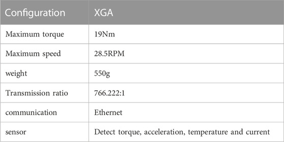
TABLE 1. XGA key joint parameters.
2.1.2 Robot kinematics model
The training diagram of the two-degree-of-freedom flexible joint upper limb rehabilitation robot could be simplified as Figure 2. The upper limb rehabilitation robot was composed of two rods (rod A and rod B),
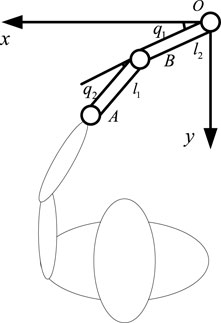
FIGURE 2. The training diagram of the two-degree-of-freedom flexible joint upper limb rehabilitation robot.
The inverse kinematics formula was derived from the forward kinematics:
2.2 Adaptive impedance control strategy
The adaptive impedance control diagram based on human impedance parameter identification was shown in Figure 3, which mainly included impedance parameter estimation of the affected limb, stiffness optimization, impedance controller, trajectory planning, inverse kinematics, and robot controller, etc. The robot first determined the rehabilitation task, chose the task node, carried out trajectory planning for the rehabilitation robot through quintic polynomial interpolation to get the expected end trajectory Xd, and then calculated the joint expected trajectory through inverse kinematics qd as the controller input. The position of the joint controller was regulated by PD control. Next, the impedance parameters Kh of the affected limb were identified online using the FFRLS. The impedance parameters of the upper limb end were also acquired. The optimal impedance Kr was calculated by equations (14) and (15), and the terminal position correction
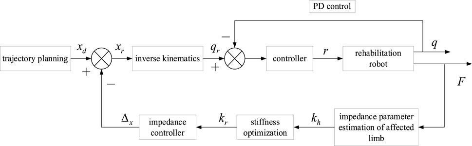
FIGURE 3. The adaptive impedance control diagram based on human impedance parameter identification.
2.2.1 Identification of upper limb impedance parameters
Some studies have considered mechanical impedance control as an important method of human motion control. The complex human arm model was simplified as a Cartesian impedance model. The internal model of the arm was transferred to the end of the human arm in the horizontal plane. Therefore, stiffness, damping, and mass became the three components of the mechanical impedance at the end of the human upper limb, relating to force, position, speed, and acceleration respectively. In order to use this model to assume human-computer interaction in the rehabilitation system, it was necessary to estimate the impedance at the end of the human arm. In this section, a model of human upper limb was established and the impedance at the end of human upper limb was estimated by FFRLS.
Since the musculoskeletal system was assumed to be a mass-spring-damping system, the dynamic motion equation of the mass-spring-damper system was used as a mathematical model to measure the dynamic impedance of the upper limb. The impedance model of the upper limb was depicted in Figure 4, which could be used to measure the dynamic impedance of the upper limb under during movement. When the upper limb was in the stable state, the impedance model of the human upper limb end in the Cartesian coordinate system could be displayed as follows:
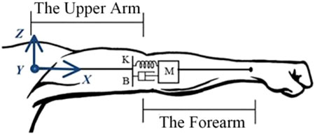
FIGURE 4. The impedance model of the human upper limb.
M, B, K
In the process of rehabilitation training, the impedance parameters of human upper limb were variable. With the changes in the rehabilitation cycle, the impedance parameters of human upper limb modified slowly. For the slow time-varying system, the recursive least square (RLS) method had its limitations. As k increased, the values of P(k) and K(k) decreased, resulting in declining corrections for
Take the cost function:
The RLS derivation formula of forgetting factor was as follows:
The method of selecting initial values
2.2.2 Optimal stiffness selection
At different stages of their rehabilitation, patients need different training modalities, requiring a specific stiffness from the rehabilitation robot (Zou et al., 2022). In order to increase the effectiveness of rehabilitation therapy assisted by rehabilitation robot, patients’ active participation must be encouraged by the robot controller (Luo et al., 2017; Guo et al., 2022a). At the same time, if the patient’s movement deviated from the expected movement, it should be restrained. Therefore, the reward function was set to balance patients’ participation and trajectory shift error. The reward function was defined as:
Eq. 9 was substituted into Eq. 8,
The reward function r took the partial derivative with respect to
In order to maximize the reward function,
During rehabilitation training, the inertia, motion acceleration, and speed of the rehabilitation robot were very small. The inertia force and Coriolis force could be safely disregarded. In addition, compared with the joint torque of the rehabilitation robot, friction was also found to be negligible. Assuming that the affected limb end achieved a stable state within a short time, the force of the rehabilitation robot was equal to that exerted by the patient:
Eq. 12 was substituted into Eq. 14 to obtain the optimal stiffness of impedance control of rehabilitation robot:
When the affected limb had minimal participation (
3 Experiment results
In order to verify the impedance identification algorithm and the adaptive impedance control technology proposed in this study, three sets of experiments were carried out in this section: impedance parameter identification verification and variable impedance control simulation experiment, as well as the adaptive impedance control verification.
3.1 Impedance parameter identification verification
As shown in Figure 5, the platform for impedance identification experiment was set up. The end handle of the rehabilitation robot was connected to the elastic body (rubber band). The other end of the elastic body was fixed, and the elastic body was fixed stiffness within a certain range. The six-dimensional force sensor with the end connected to the grip could measure the force and the torque in three directions in Cartesian space. The Cartesian coordinate system was installed at the rotation center of the first joint. Since the experiment platform belonged to the tabletop upper limb rehabilitation robot, only coordinate systems in the x and y directions were established.
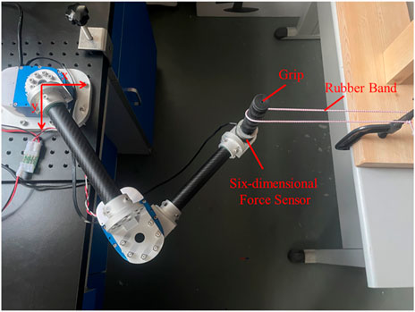
FIGURE 5. The impedance identification experiment platform.
Since the peak moment of the joint was 19 Nm, a spring with excessive stiffness could not be used for the impedance parameter identification experiment. Therefore, a rubber band chosen for the experiment had an elastic stiffness of 25 N/m. The end stiffness parameters were varied by changing the number of strands, stiffness, and position of the rubber bands. Firstly, two strands of rubber bands were selected for the impedance parameter identification experiment. The initial point of the end was (0.4 m, 0), and the movement was planned to (0.3 m, 0). The trajectory planning adopted the quintic polynomial interpolation method. Under the initial condition of the experiment, the elastic band was just taut, and the force sensor could detect the tension of the elastomer at the end, which was in the same plane as the elastomer at the other fixed end. It was planned to move from point A (0.4 m, 0) to point B (0.3 m, 0). The trajectory planning results in the x direction were shown in the following figure using quintic polynomials. The position, speed, and acceleration of the end from top to bottom were illustrated in Figure 6A. It could be observed that the speed and acceleration in the initial and terminal states were 0. This method could successfully avoid the impact of the rehabilitation robot on the motor during the process of starting and stopping. Meanwhile, the smooth trajectory also made the rehabilitation process more steady, which was beneficial to the rehabilitation of the affected limb. The expected trajectories of the two joints were obtained by inverse kinematics, as shown in Figure 6B,
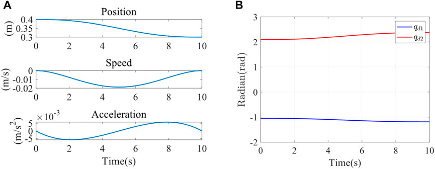
FIGURE 6. (A) X-direction trajectory planning in Cartesian space. (B) Joint 1 and joint 2 expected trajectory.
The interaction force
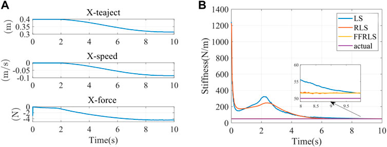
FIGURE 7. (A) The input parameters of impedance identification experiment (B) Impedance parameter identification results.
Impedance parameter identification errors were shown in Table 2. Since the stiffness estimation of the first few seconds by RLS and LS was divergent, it did not have statistical significance. All data in Table 2 were calculated after the stiffness identification curves of FFRLS, RLS, and LS. The root-mean-square errors of stiffness identification by FFRLS (
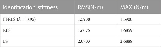
TABLE 2. Impedance parameter identification errors.
3.2 Variable impedance control simulation verification
The feasibility of the above impedance control was verified by simulation in Matlab 2023a. To verify the system’s ability of control stiffness under the external disturbances, we simulated the stiffness of the upper limb end of the healthy participants by modifying impedance parameters, thereby altering the system’s stiffness behavior. This demonstrated its control capability over impedance characteristics. The simulation platform was set up based on actual platform parameters. The parameters of kinematic model were set as follows: m1 = 1 kg, m2 = 0.7 kg, I1 = 0.25, I2 = 0.1, ll = l2 = 0.4, lc1 = lc2 = 0.2; m1 and m2 were the masses of rods A and B respectively. ll and l2 were the lengths of rods A and B respectively. lc1 and lc2 were the distances from the center of mass of rods A and B to the rotation center, respectively. I1 and I2 were the moments of inertia of rods A and B, respectively. Parameter g represented the gravitational acceleration and was taken as 9.8 m/s. The control stiffness parameter was established as follows:
The end load of Cartesian coordinate system was established as follows:
That is, the stiffness changed at a fixed frequency within a certain range, which was reflected in the varying stiffness of the manipulator’s end in different directions on the plane. As shown in Figure 8, the solid and dashed lines were the curves of the stiffness of the two different joints of the robot over time.
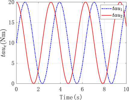
FIGURE 8. The stiffness of two different joints of the robot.
Under the above external conditions, the corresponding load force was applied to it. And it was expected that the resulting torque output and error performance could reflect the stiffness control performance. Figures 9A,B were the position tracking error and the derivative change curve caused by the impedance control of the two joints of the robot, respectively. As observed in Figure 9A, in the face of the load imposed by the external environment, the tracking error
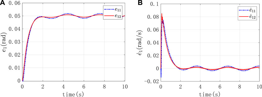
FIGURE 9. (A) The position tracking error caused by the impedance control (B) The derivative change curve caused by the impedance control.
Figure 10 was the graph of the output torque of the two joints changing over time, and it displayed that the joint itself output the corresponding output torque to counteract the external input torque.
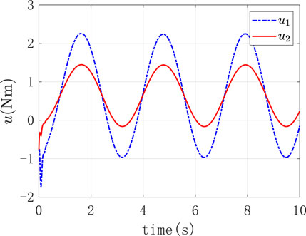
FIGURE 10. The output torque of the two joints.
3.3 Adaptive impedance control verification
To verify the adaptive impedance control system in this study, a healthy male participant (24 years old, 1.88 m in height, 84 kg in weight) was recruited in the experiments, as shown in Figure 1, The study was reviewed by Shanghai University of Medicine and Health Sciences ethics, batch number 2022-ZYXM4-04-420300197109053525. The experiment was designed as follows: the rehabilitation task required the subject to move the end of the upper limb from A (0.5 m, 0) to C (0.2 m, 0), and each training time was 10s. Under the condition of constant impedance control and adaptive impedance control, the experiments were carried out with varying participation of the affected limb (i.e., different impedance parameters). The trajectory planning results of x direction using quintic polynomials were reported in Figure 11A, including the position, speed, and acceleration of the end from top to bottom. At the starting point A and the end point C, there was no speed or acceleration. This approach effectively reduced the impact of the rehabilitation robot on the motor during the phases of starting and stopping. Furthermore, the well-executed trajectory enhanced the overall stability of the rehabilitation process, thereby promoting the recovery of the affected limb. The expected trajectories of both joints were determined by inverse kinematics, as illustrated in Figure 11B.
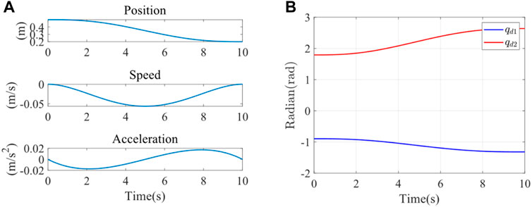
FIGURE 11. (A) X-direction trajectory planning (B) Expected trajectory of joint 1 and joint 2.
The parameters
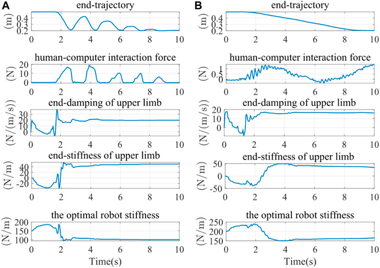
FIGURE 12. The results of experiments under different conditions of the participation. (A) High participation experiment results (B) Low participation experiment results.
The terminal trajectories and interaction forces for both the constant impedance control (Kd = 100 N/m) and the adaptive impedance control were shown in Figure 13A. In both experiments, the interactive forces of adaptive impedance and constant impedance consistently showed high participation levels for the affected limb. Demonstrating that The reward obtained from the adaptive impedance control during the rehabilitation training was significantly higher than that of the constant impedance control with Kd = 100 N/m, as illustrated by the reward functionsin Figure 13B. This confirmed the effectiveness and robustness of the adaptive impedance control strategy proposed in this study.
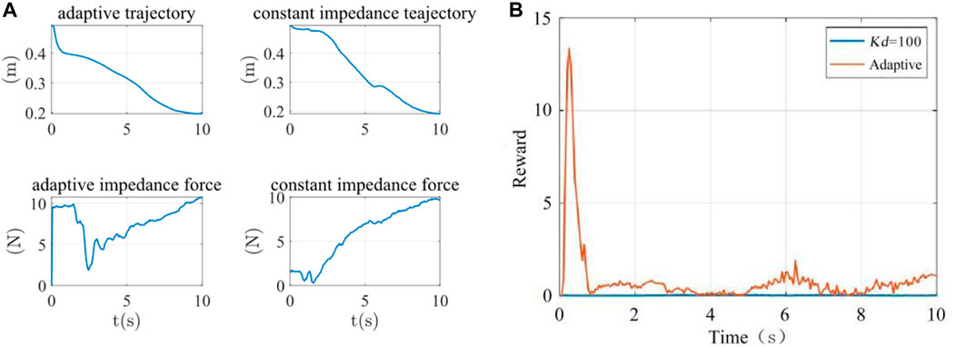
FIGURE 13. (A) The terminal trajectory and interaction force (B) Reward function.
The analysis of the reward function was shown in Table 3. The average rewards of constant impedance control (Kd = 100 N/m) and adaptive impedance control were 0.0152 and 0.8514, and the maximum rewards were 0.0471 and 13.3437, respectively.

TABLE 3. The analysis of reward function.
4 Discussion
In this study, we constructed a mechanical platform and developed a novel adaptive impedance control strategy for the upper limb rehabilitation robot. We utilized a mass-spring-damping system to simulate the musculoskeletal system. With the changes in rehabilitation cycle, we used FFRLS to improve the accuracy of parameter estimation error. This method, in contrast to earlier LS or RLS, could constantly track changes in the impedance parameters online and did not decrease system parameter identification due to increased stiffness. We employed the reward function to strike a balance between the subject’s participation and the trajectory deviation error, further achieving the optimal stiffness of impedance control of the rehabilitation robot.
Various techniques were employed in some studies to estimate and adjust participants’ optimal stiffness. An algorithm that could adaptively change the impedance control’s stiffness parameters in response to the observed values of the interaction force between patients and robots was proposed by Riener et al. Through the linear adaptive law, when the workload of the patient was detected to increase, the stiffness value was reduced (Riener et al., 2005). Ground on the evaluation of human active torque, Shahid et al. employed a similar method to control the stiffness of the manipulator (Hussain et al., 2013). Although their methods achieved control results, this study fully considered the levels of the subject’s participation and enthusiasm in rehabilitation training in the form of a reward function. Patients’ active participation awareness played a significant role in promoting the effect of rehabilitation training (Pawlak et al., 2022).
Moreover, this study designed the experiments under different participation to get the different parameters from the robot. When patients showed the signs of fatigue or reduced movement ability, the robot could increase the assistance level to maintain training continuity and efficacy, avoiding potential secondary injuries or training outcomes (Yang et al., 2023). Conversely, when patients exhibited a high level of participation, the robot might reduce its assistance to encourage patients to make more use of their own muscle, which supported neural plasticity and the rehabilitation of motor functions (Kawahira et al., 2010). Further studies via this approach enables more personalized rehabilitation training, satisfying the specific needs of different patients, thereby improving the efficiency of rehabilitation and accelerating the patient’s return to normal life and work.
In the simulation experiment, it was observed that the corresponding torque output at the end of the robotic arm could resist the corresponding load force when the platform was facing variable external load force and the error was controlled within a narrow range, proving the effectiveness of the adaptive impedance control strategy. The limit of the simulation was that the stiffness change law was set by ourselves to simulate the actual situation. However, the output stiffness value of the assist-as-needed strategy was optimized according to the stiffness of the affected limb. We will optimize the experimental settings by taking assist-as-needed rehabilitation procedures into account in subsequent studies.
Since impedance control achieved regulation and stabilization of robot motion by establishing a mathematical relationship between the interaction forces and the reference trajectories (Al-Shuka et al., 2018), we compared adaptive impedance control and constant impedance control for experimental verification. By setting different parameters to simulate varying levels of participant engagement, the results obtained were consistent with the experiment in which a healthy subject was involved. We also obtained that the average and maximum rewards of adaptive impedance control were higher than those of constant impedance control at Kd = 100 N/m. Luo, Duan, and Berenice conducted comparative simulation experiments on constant impedance control and variable impedance control (Luo et al., 2017; Maldonado et al., 2015; Duan et al., 2018). In these researches, Luo used different levels of simulated stiffness values, Duan compared the two methods in different environments, and Berenice simulated the situations of subjects under different task modes. Their research findings indicated that adaptive impedance control had better force tracking performance and potential for facilitating rewards compared to constant impedance control. Adaptive impedance control technology can be utilized in robot-assisted rehabilitation systems under various conditions which further prove the effectiveness of adaptive impedance control in rehabilitation training. Ibarra and Wang also suggested adaptive impedance control strategies, considering the influence of patients on the ankle rehabilitation robot and adjusting the robot aids in real time (Perez-Ibarra et al., 2015; Wang et al., 2019). The intervention of the exoskeleton was considered in the process of training (Guo et al., 2022b).
This control strategy offered significant potential for achieving the best active training effect and creating a controllable impedance environment for the patient. The adaptive control strategy can improve the performance of the human-robot interaction and the effectiveness of the control system for upper limb rehabilitation robot. In addition, the proposed strategy could also be applied to the different rehabilitation robots. In our follow-up studies, we will test the proposed method with more healthy subjects and patients to accurately identify the differences based on the different participation, and we will also apply this control system for the wearing assistive devices to test its effectiveness, improving the rehabilitation efficacy eventually.
5 Conclusion
In this study, an novel adaptive impedance strategy for upper-limb rehabilitation robots was proposed. The efficacy of optimal stiffness control was confirmed through a comparison of performance across various levels of upper limb participation during the rehabilitation process. A comparison of rehabilitation performance between adaptive impedance control and consant impedance control was also conducted. The simulation and the experiments fully verified the effectiveness of this adaptive impedance control strategy.
Data availability statement
The original contributions presented in the study are included in the article/Supplementary Material, further inquiries can be directed to the corresponding author.
Ethics statement
The studies involving humans were approved by Shanghai University of Medicine and Health Sciences ethics. The studies were conducted in accordance with the local legislation and institutional requirements. Written informed consent for participation in this study was provided by the participants’ legal guardians/next of kin. Written informed consent was obtained from the individual(s) for the publication of any potentially identifiable images or data included in this article.
Author contributions
YZ: Project administration, Supervision, Writing–review and editing. TL: Data curation, Formal Analysis, Validation, Writing–original draft. HT: Data curation, Formal Analysis, Methodology, Writing–original draft. FL: Formal Analysis, Writing–review and editing. BH: Funding acquisition, Project administration, Writing–review and editing. MW: Supervision, Writing–review and editing. HY: Project administration, Resources, Supervision, Writing–review and editing.
Funding
The author(s) declare financial support was received for the research, authorship, and/or publication of this article.
Acknowledgments
The authors appreciatively acknowledge the financial support from the National Key Research and Development Program of China under Grant 2022YFC3601400 and the Biomedical Science and Technology Support Project of Shanghai under Grant 22S31901400.
Conflict of interest
The authors declare that the research was conducted in the absence of any commercial or financial relationships that could be construed as a potential conflict of interest.
Publisher’s note
All claims expressed in this article are solely those of the authors and do not necessarily represent those of their affiliated organizations, or those of the publisher, the editors and the reviewers. Any product that may be evaluated in this article, or claim that may be made by its manufacturer, is not guaranteed or endorsed by the publisher.
Supplementary material
The Supplementary Material for this article can be found online at: https://www.frontiersin.org/articles/10.3389/fbioe.2023.1332689/full#supplementary-material
References
Albu-Schaffer, A., Ott, C., and Hirzinger, G. (2007). A unified passivity based control framework for position, torque and impedance control of flexible joint robots. Springer Trac. Adv. Ro 28, 5–21. doi:10.1177/0278364907073776
Al-Shuka, H. F. N., Leonhardt, S., Zhu, W.-H., Song, R., Ding, C., and Li, Y. (2018). Active impedance control of bioinspired motion robotic manipulators: an overview. Appl. Bionics Biomechanics 2018, 1–19. doi:10.1155/2018/8203054
Brahmi, B., Driscoll, M., El Bojairami, I. K., Saad, M., and Brahmi, A. (2021). Novel adaptive impedance control for exoskeleton robot for rehabilitation using a nonlinear time-delay disturbance observer. Isa T 108, 381–392. doi:10.1016/j.isatra.2020.08.036
Duan, J., Gan, Y., Chen, M., and Dai, X. (2018). Adaptive variable impedance control for dynamic contact force tracking in uncertain environment. Robotics Aut. Syst. 102, 54–65. doi:10.1016/j.robot.2018.01.009
Guo, Y. D., Wang, H. P., Tian, Y., and Caldwell, D. G. (2022a). Task performance-based adaptive velocity assist-as-needed control for an upper limb exoskeleton. Biomed. Signal Proces., 73. doi:10.1016/j.bspc.2021.103474
Guo, Y. D., Wang, H. P., Tian, Y., and Xu, J. Z. (2022b). Position/force evaluation-based assist-as-needed control strategy design for upper limb rehabilitation exoskeleton. Neural Comput. Appl. 34 (15), 13075–13090. doi:10.1007/s00521-022-07180-x
Hong, Z., Sui, M., Zhuang, Z., Liu, H., Zheng, X., Cai, C., et al. (2018). Effectiveness of neuromuscular electrical stimulation on lower limbs of patients with hemiplegia after chronic stroke: a systematic review. Archivees Phys. Med. rehabilitation, 1532–1821. doi:10.1016/j.apmr.2017.12.019
Honghai, L., Zhouping, Y., and Lianqing, L. (2022). “Intelligent robotics and applications,” in 15th International Conference, ICIRA 2022, Harbin, China, August, 2022.
Hussain, S., Xie, S. Q., and Jamwal, P. K. (2013). Adaptive impedance control of a robotic orthosis for gait rehabilitation. Ieee T Cybern. 43 (3), 1025–1034. doi:10.1109/tsmcb.2012.2222374
Islam, M. R., Assad-Uz-Zaman, M., Brahmi, B., Bouteraa, Y., Wang, I., and Rahman, M. H. (2021). Design and development of an upper limb rehabilitative robot with dual functionality. Micromachines 12, 870. doi:10.3390/mi12080870
Kawahira, K., Shimodozono, M., Etoh, S., Kamada, K., Noma, T., and Tanaka, N. (2010). Effects of intensive repetition of a new facilitation technique on motor functional recovery of the hemiplegic upper limb and hand. Brain Inj. 24 (10), 1202–1213. doi:10.3109/02699052.2010.506855
Krebs, H. I., Palazzolo, J. J., Dipietro, L., Volpe, B. T., Hogan, N., Rannekleiv, K., et al. (2003). Rehabilitation robotics: performance-based progressive robot-assisted therapy. Auton. Robot. 15 (1), 7–20. doi:10.1023/a:1024494031121
Li, X., Liu, Y. H., and Yu, H. Y. (2018). Iterative learning impedance control for rehabilitation robots driven by series elastic actuators. Automatica 90, 1–7. doi:10.1016/j.automatica.2017.12.031
Long, T., Wang, S. L., Cao, W., Zhou, H., and Fernandez, C. (2023). An improved variable forgetting factor recursive least square-double extend Kalman filtering based on global mean particle swarm optimization algorithm for collaborative state of energy and state of health estimation of lithium-ion batteries. Electrochim Acta, 450. doi:10.1016/j.electacta.2023.142270
Luo, L., Peng, L., Hou, Z., and Wang, W. (2017). “An adaptive impedance controller for upper limb rehabilitation based on estimation of patients' stiffness,” in 2017 IEEE International Conference on Robotics and Biomimetics (ROBIO), Macau, Macao, December, 2017, 532–537.
Ma, Q., Li, R., Wang, L., Yin, P., Wang, Y., Yan, C., et al. (2021). Temporal trend and attributable risk factors of stroke burden in China, 1990-2019: an analysis for the Global Burden of Disease Study 2019. Lancet Public Health 6 (12), e897–e906. doi:10.1016/s2468-2667(21)00228-0
Maldonado, B., Mendoza, M., Bonilla, I., and Reyna-Gutiérrez, I. (2015). “Stiffness-based tuning of an adaptive impedance controller for robot-assisted rehabilitation of upper limbs,” in 2015 37th Annual International Conference of the IEEE Engineering in Medicine and Biology Society (EMBC), Milan, Italy, August 2015, 3578–3581.
Pawlak, N. D., Serafin, L., and Czarkowska-Pączek, B. (2022). Relationship between patients’ subjective involvement in postoperative rehabilitation and quality of life after arthroscopic treatment for osteoarthritic knee – cross-sectional study. Med. Og. Nauk. Zdr. 28 (1), 63–69. doi:10.26444/monz/143835
Pehlivan, A. U., Losey, D. P., and O'Malley, M. K. (2016). Minimal assist-as-needed controller for upper limb robotic rehabilitation. Ieee T Robot. 32 (1), 113–124. doi:10.1109/tro.2015.2503726
Perez-Ibarra, J. C., Siqueira, A. A. G., and Krebs, H. I. (2015). Assist-as-needed ankle rehabilitation based on adaptive impedance control. Int. C Rehab Robot., 723–728. doi:10.1109/ICORR.2015.7281287
Perez-Ibarra, J. C., Siqueira, A. A. G., Silva-Couto, M. A., de Russo, T. L., and Krebs, H. I. (2019). Adaptive impedance control applied to robot-aided neuro-rehabilitation of the ankle. Ieee Robot. Autom. Let. 4 (2), 185–192. doi:10.1109/lra.2018.2885165
Riener, R., Lunenburger, L., Jezernik, S., Anderschitz, M., Colombo, G., and Dietz, V. (2005). Patient-cooperative strategies for robot-aided treadmill training: first experimental results. Ieee Trans. Neural Syst. Rehabilitation Eng. 13 (3), 380–394. doi:10.1109/tnsre.2005.848628
Sharifi, M., Behzadipour, S., Salarieh, H., and Tavakoli, M. (2017). Cooperative modalities in robotic tele-rehabilitation using nonlinear bilateral impedance control. Control Eng. Pract. 67, 52–63. doi:10.1016/j.conengprac.2017.07.002
Sun, T., Wang, Z., He, C., and Yang, L. (2022). Adaptive robust admittance control of robots using duality principle-based impedance selection. Appl. Sci. 12, 12222. doi:10.3390/app122312222
Vanoglio, F., Bernocchi, P., Mulè, C., Garofali, F., Mora, C., Taveggia, G., et al. (2016). Feasibility and efficacy of a robotic device for hand rehabilitation in hemiplegic stroke patients: a randomized pilot controlled study. Clin. Rehabil. 31 (3), 351–360. doi:10.1177/0269215516642606
Vasu, S., Luis, G., and Dileep, R. Y. (2021). Global epidemiology of stroke and access to acute ischemic stroke interventions. Neurology 97 (20 Suppl. 2), S6–S16. doi:10.1212/wnl.0000000000012781
Wang, C., Peng, L., Hou, Z. G., Wang, W. Q., and Su, T. T. (2019). “A novel assist-as-needed controller based on fuzzy-logic inference and human impedance identification for upper-limb rehabilitation,” in 2019 Ieee Symposium Series on Computational Intelligence, Xiamen, China, December 2019, 1133–1139.
Wolbrecht, E. T., Chan, V., Reinkensmeyer, D. J., and Bobrow, J. E. (2008). Optimizing compliant, model-based robotic assistance to promote neurorehabilitation. IEEE Trans. Neural Syst. Rehabilitation Eng. 16 (3), 286–297. doi:10.1109/tnsre.2008.918389
Xu, G. Z., Gao, X., Chen, S., Wang, Q., Zhu, B., and Li, J. F. (2017). A novel approach for robot-assisted upper-limb rehabilitation: progressive resistance training as a paradigm. Int. J. Adv. Robot. Syst. 14 (6), 172988141773667. doi:10.1177/1729881417736670
Yang, R., Shen, Z., Lyu, Y., Zhuang, Y., Li, L., and Song, R. (2023). Voluntary assist-as-needed controller for an ankle power-assist rehabilitation robot. IEEE Trans. Biomed. Eng. 70 (6), 1795–1803. doi:10.1109/tbme.2022.3228070
Keywords: rehabilitation robot, upper limb, impedance identification, adaptive impedance control, optimal stiffness
Citation: Zhang Y, Li T, Tao H, Liu F, Hu B, Wu M and Yu H (2024) Research on adaptive impedance control technology of upper limb rehabilitation robot based on impedance parameter prediction. Front. Bioeng. Biotechnol. 11:1332689. doi: 10.3389/fbioe.2023.1332689
Received: 03 November 2023; Accepted: 08 December 2023;
Published: 03 January 2024.
Edited by:
Wujing Cao, Chinese Academy of Sciences (CAS), ChinaReviewed by:
Dongyang Shang, Northeastern University, ChinaYue Ma, Chinese Academy of Sciences (CAS), China
Copyright © 2024 Zhang, Li, Tao, Liu, Hu, Wu and Yu. This is an open-access article distributed under the terms of the Creative Commons Attribution License (CC BY). The use, distribution or reproduction in other forums is permitted, provided the original author(s) and the copyright owner(s) are credited and that the original publication in this journal is cited, in accordance with accepted academic practice. No use, distribution or reproduction is permitted which does not comply with these terms.
*Correspondence: Minghui Wu, d3VtaW5naHVpQHN1ZXMuZWR1LmNu; Hongliu Yu, eWhsX3Vzc3RAb3V0bG9vay5jb20=