- 1Hubei Digital Textile Equipment Key Laboratory, Wuhan Textile University, Wuhan, Hubei, China
- 2School of Mechanical Engineering and Automation, Wuhan Textile University, Wuhan, Hubei, China
In the biomedical field, polyurethane (PU) is widely used in interventional catheters, artificial hearts, artificial blood vessels, orthopedic materials, medical adhesives, and other medical devices. In this paper, a method based on machine vision was proposed to control the drafting and winding accuracy of PU filament in order to solve the problem of centrifugal runout when the mold rotates. The centrifugal runout of the mold directly affected the preparation efficiency and quality of long artificial blood vessel by wet spinning. Through non-contact real-time detection of the filament diameter and the angle between the axis of filament and the axis of mold, the motion parameters of the two motors driving the moving platform and the drafting roller could be adjusted in real time to achieve the purpose of online real-time control of filament drafting and winding accuracy. The vision control method proposed in this paper was used to carry out the PU tube preparation experiment. The visual measurement results of the filament diameter and the included angle were compared with the manual measurement results. The average value of the diameter error is 0.0096mm, and the average value of winding angle is 0.4777°. The results proved the accuracy of the visual measuring method and testified it feasible to using machine vision instead of manual method to detect filament diameter and winding angle. Properties of the prepared PU tube were tested and analyzed. The filament diameter measured by the 3D microscope was about 0.87 mm and significantly smaller than the filament diameter before winding. This indicated that the winding was uniform, the extrusion was tight, and the adhesion was good.
Introduction
With the continuous research and development of polymer materials, their good performance has attracted extensive attention in the fields of mechanical engineering, textile engineering, aerospace, electronics, biomedicine, chemistry, military industry, architecture and so on. (Cheng and Zhao, 2017; Qu, 2018; Bao, 2019). In the biomedical field, the main applications of polymer materials are artificial organs, artificial tissues, and medical polymer materials. At present, biomedical polymer materials are divided into natural biopolymer materials and synthetic biopolymer materials. For example, cellulose and collagen are natural polymer materials, while PU, silicone rubber and polyethylene are high molecular materials prepared by chemical synthesis (Liang and Huang, 2016). The PU materials can obtain appropriate mechanical properties, wear resistance, elasticity, hydrophobicity, and other properties by adjusting the proportion of components. This makes the research and application of PU materials in the fields of cardiovascular system, urinary system, in vitro body surface and tissue repair have great potential value (Shao et al., 2022). The mechanical properties of PU could also be improved by chemical modification, so that it can be applied and studied in more fields (Wu et al., 2015). For example, Li et al. (2013) modified PU with boron nitride nanotubes to make boron nitride nanotubes (BNNT) PU composites with different volume fractions. Zhang and Su (2012) filled carbon nanotubes into PU to obtain composites with good mechanical properties. Wang et al. (2009) modified PU coating with nano ZnO to improve its anti-aging performance.
Since the 1980s, PU has been widely used in interventional catheters, artificial hearts, artificial blood vessels, orthopedic materials, medical adhesives, and other medical devices (Uscategui et al., 2018). The precision control of PU filament drafting and winding proposed in this paper is to prepare high-quality PU artificial blood vessels. At present, the clinical performance of large caliber (>6 mm) artificial blood vessels is good, while the clinical performance of small caliber (≤6 mm) artificial blood vessels is poor. The main problem is that the suture site of small caliber artificial blood vessel is easy to produce intimal hyperplasia which makes the lumen narrower and leads to thrombosis. Thrombus will affect the patency rate of blood vessels in the body, resulting in the shortening of the life of artificial blood vessels and the need for reoperation. Because of the low production efficiency and high cost of artificial blood vessels, many patients with vascular diseases missed the best treatment time (Wu et al., 2020). Therefore, in recent years, in order to prepare small caliber artificial blood vessels suitable for human body, scientific research workers have done researches on a variety of different materials and produced a series of artificial blood vessels of different materials, such as polyester artificial blood vessels, expanded polytetrafluoroethylene artificial blood vessels, silk artificial blood vessels and PU artificial blood vessels (Shaker et al., 2019).
Among them, PU artificial blood vessel is considered as the best material for making small caliber artificial blood vessel (Xu et al., 2012; Cheng and Fu, 2017), because of its excellent mechanical properties, biocompatibility, water permeability, fatigue resistance, and compliance matching with natural blood vessel. At the same time, its structural design and modification can further improve its performance in human body. In recent years, there are more and more methods to prepare artificial blood vessels with PU materials, such as electro-spinning (Christian et al., 2010), freeze-drying multi-step (Wang Q et al., 2004; Gao et al., 2014), spray phase transformation (Yaguchi, 2002), impregnation (Miyamoto et al., 2002; Pan et al., 2008), wet spinning (Zhang, 2015), etc.
Among them, the impregnation method, freeze-drying multi-step method and spray phase transformation method are more complex and time-consuming, which are not conducive to production. Electro-spinning method is similar to wet spinning method, which first prepares PU materials into filament and then winds them. However, compared with wet spinning method, electro-spinning method is more cumbersome, and it is not easy to improve the porosity of PU filament. Large porosity can accelerate the process of endothelial cell formation and improve the compliance of artificial blood vessels.
The tube preparation method studied in this paper was the wet spinning method. The conventional artificial blood vessel preparation is only a few hundred millimeters long. However, the total length of the PU tube prepared in this paper can reach 1400 mm. The mold used is a stainless-steel pipe with and outer diameter of 6mm, a wall thickness of 1 mm and a length of 2000 mm. Therefore, the overall weight of the mold is large and the length diameter ratio is large. Under the clamping conditions of support at both ends and suspension in the middle, the mold is an arc, as shown in Figure 1A.
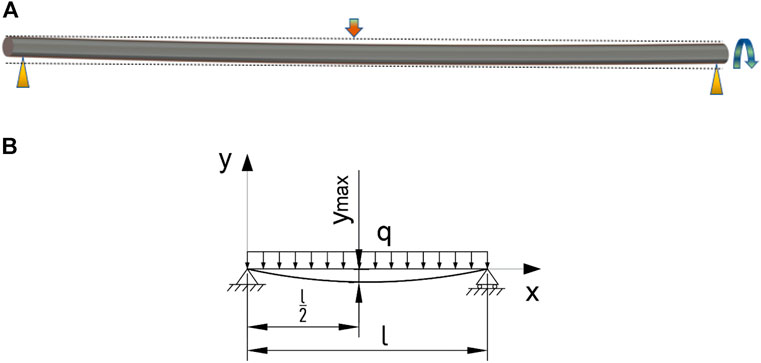
FIGURE 1. Diagram of mold deformation and force analysis. (A) Diagram of mold deformation. (B) Diagram of force analysis.
When only the self-weight is considered, there is only the uniformly distributed load
This directly affects the preparation efficiency and quality of PU tubes. Therefore, the machine vision detection technology was added to the PU filament preparation and PU corrugated tube integrated forming equipment involved in this paper, and used to monitor the forming process of PU tube in real time. The quality of the prepared PU tube was ensured by adjusting the motion parameters. The production efficiency of PU tube could be further improved in the case of unavoidable mold runout. The quality of the PU tube is also reflected in its overall uniformity and film-forming property. Film-forming property refers to the strength of the bonding property of the adjacent two coils of PU filament during the winding process. And the better the film-forming property, the better the mechanical property of the PU tube. There are certain requirements for the diameter and winding process of the PU filament, that is, the diameter of the PU filament should maintain a certain uniformity and the winding process shall ensure the close connection of adjacent filament coils.
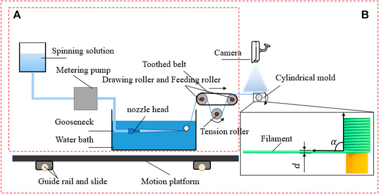
In this paper, the preparation method of PU tube based on machine vision was proposed. The preparation flow and visual control diagram are shown in Figure 2 and Figure 3. Part A in Figure 2 mainly refers to the drawing part of PU.
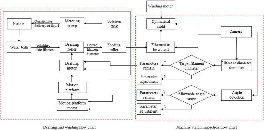
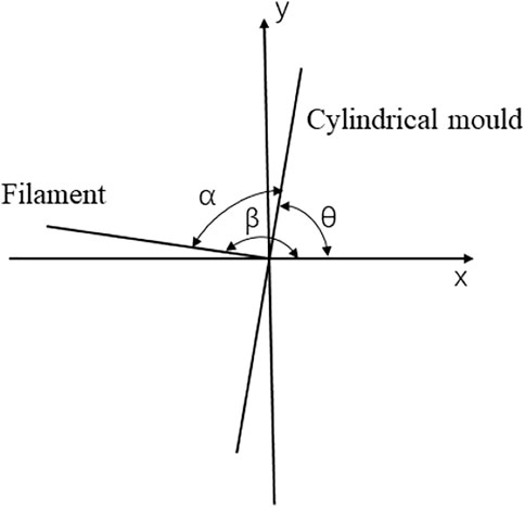
Filament and Part B in Figure 2 refers to the visual inspection and winding part. The hardware facilities mainly include the storage tank of spinning stock solution, metering pump for quantitative solution delivery, small diameter spinneret, water bath, drafting mechanism, winding mechanism, visual camera, and motion platform. Figure 3 showed the preparation process, visual inspection, and target quantity to be controlled of the whole tube. The motion of the drafting mechanism was an important parameter that affected the diameter of PU filament (Wang Z. X et al., 2004; Zhao, 2019), while the motion parameters of the motion platform mainly affect the winding quality. The filament diameter and winding angle could be controlled only by controlling the speed of the drafting roller and the moving speed of the moving platform, to ensure the overall quality of the tube prepared. The winding angle is the included angle between the PU filament axis and the mold axis.
In the previous research, the control of filament diameter and winding angle were mainly observed by human eyes and adjusted according to experience, which led to unstable quality, low efficiency, and large error. It was impossible to directly measure the filament diameter and winding angle by contact method in the preparation process. Therefore, machine vision technology was adopted in the preparation process of PU tube. And the motion parameters were compensated and calculated through the algorithm to form a closed control loop and realize non-contact real-time control, as shown in Figure 3.
The non-contact measurement technology is mainly used in the measurement of high-risk environment, harsh environment, continuous moving objects, and vulnerable products. The existing non-contact measurement methods include electromagnetic induction method (Wu et al., 2013), laser detection method (Zhou, 2009; Li and Cao, 2020), prism free total station non-contact measurement method (Yao, 2020), machine vision detection method (Xiao et al., 2022), etc. The preparation process of PU tube is a high-speed movement process. The controlling of drafting and winding accuracy studied in this paper is completed synchronously in this process, so the machine vision method is more reasonable.
Machine vision which involves the interdisciplinary fields of computer science, image processing and pattern recognition, is an important branch of AI (Xie et al., 2022). It is known as the “eye of industry”, and it is a key technology used to replace the human eye to realize accurate detection, measurement, and control equipment (Liu and Yang, 2021; Zhu et al., 2022). Currently, the commonly used image processing libraries in machine vision include OpenCV, HALCON, MATLAB, VisionPro and LabVIEW.
Although VisionPro has a large market share in North America, its high runtime software license cost, lack of GPU processing and limited 3D visual algorithm library make it not favored by programmers. OpenCV is an open-source code library, which is inconvenient to debug, and its project development cycle is long. Although LabVIEW has high development efficiency, the accuracy and stability of the algorithm under its platform depend on image quality. HALCON is an image processing library under MVTec company in Germany. It has powerful 2D and full range 3D machine vision libraries. Its application scope covers positioning recognition, barcode/QR code recognition, measurement fitting, OCR tools, general visual inspection, defect detection, etc. The price of runtime license is greatly reduced. HALCON provides higher bit depth image processing and supports common operating systems and embedded devices, which makes more and more machine vision practitioners use HALCON to complete projects.
The machine vision related work completed in this paper mainly includes camera calibration, image acquisition, image processing and feature extraction. The calibration template provided by HALCON was used in the calibration. And the radial distortion of the lens and the solution method (Gao et al., 2020) are considered. The function library of HALCON was given full play to, which improved the calibration accuracy and calculation efficiency. And it effectively monitored and regulated the drafting and winding process in the process of PU tube preparation, ensuring the stability of tube preparation, providing the technical support for improving the preparation efficiency of artificial blood vessels, and the reference for the wet spinning process and detection of other materials.
Visual measure of filament diameter and included angle
In the process of PU spinning and winding, the drafting mechanism could control the filament diameter, and the moving speed of the moving platform could determine the angle between the filament and the mold. In the actual preparation process of PU tubes, it was found that if all parameters were set to constant values, the filament diameter would slowly increase with the passage of time, and the increase of filament diameter would also change the angle between the filament and the mold, resulting in poor quality of PU tubes or the preparation failure. In this paper, the machine vision was adopted to detect the filament diameter as well as included angle in real time and the differences between the target values were calculated to obtain new parameters. These new parameters were sent to the control motor, to achieve the purpose of controlling the filament diameter accuracy and winding accuracy. The overall visual inspection flow was shown as Figure 4.
Camera and light source
Machine vision system is basically composed of the camera and light source. The camera is equivalent to the eye. The light source is the key to ensure that the camera can capture the image. A suitable light source directly affects the quality of acquired images, reduces the possible noise in image, reduces the difficulty of image recognition, and improves the positioning and detection accuracy of the machine vision system.
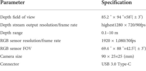
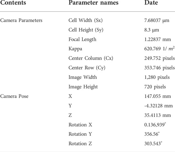
The camera used in this paper is an Intel RealSense depth camera d435i camera. Its main functional parameters are shown in Table 1.
Several common light sources were compared and white LED lamp was selected as the light source in this paper. LED lamp has many kinds of colors, long working life and various shapes, and it can meet different working environments. Fluorescent lamp is cheap, but it has a lot of heat. Xenon lamp has a short working life and a lot of heat. The heat of the light sources has a certain impact on the filament. The cost of halogen lamp is low, but the intensity is insufficient, which affects the effect of image acquisition. Specific properties of common light sources are listed in Table 2.
Camera calibration
Camera calibration is the process of determining the internal and external parameters and distortion parameters of the camera. The distortion of camera lens is the general term of the inherent perspective distortion of optical lens. In the process of image acquisition, there is produce distortion when the path points pass through the camera lens, resulting in the geometric distortion of the image. The distortion cannot be eliminated, so it is necessary to calibrate the camera to correct the distortion. Whether it is image measurement or machine vision application, the calibration of camera parameters is very important. The accuracy of calibration results and the stability of algorithm directly affect the accuracy of machine vision systems. There are many camera calibration methods, and the camera calibration function of HALCON is suitable for many occasions. And it was the calibration method adopted in this paper.
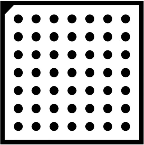
When calibrating the camera, the operator gen_caltab in HALCON is used to generates a calibration plate with seven rows and seven columns, and the distance between the centers of circles is 12.5 mm. The distance between the centers of two adjacent circles is twice the diameter of a single dot, so that the size of the calibration plate is 1/3 to 1/2 of the camera’s field of view, as shown in Figure 5. The calibration steps contain: loading 15–20 images of the calibration board through the offline image loading method, selecting the image with the most appropriate position as the reference pose, calibrating to finally obtain the internal and external parameters of the camera. The specific calibration result data were shown in Table 3.
Image acquisition
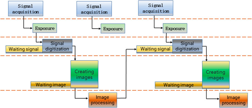
Image acquisition is an important part of machine vision system. It converts the main part and characteristics of visual image into a series of data which can be processed by computer. In the HDevelop development environment of HALCON, there are two image acquisition modes: synchronous acquisition and asynchronous acquisition. In the process of synchronous acquisition, image capturing and image processing are carried out in sequence. After image capturing, Handle of image is generated and then image processing is carried out. After image processing, the next frame of image is captured after waiting for the next acquisition instruction. The specific process is shown in Figure 6.
However, in the process of synchronous acquisition, the working mode is to send the acquisition signal according to the frequency of the frame rate set by the camera. This may cause the signal of the next frame to be missed after the image processing is completed, and the image of the middle frame may be also lost. In this case, the actual frame rate may not reach the theoretical frame rate set by the camera.
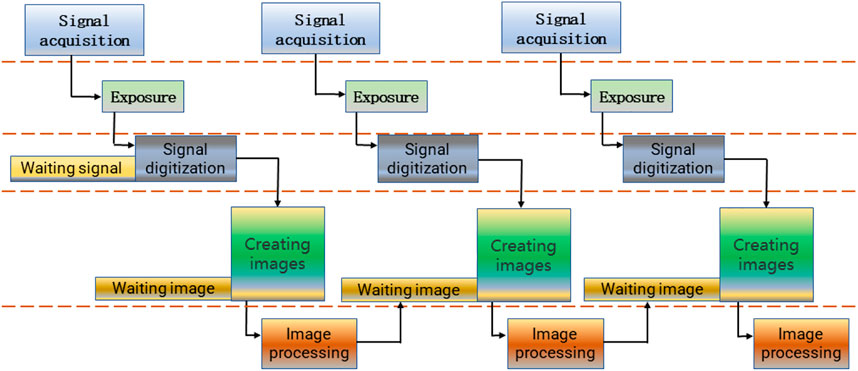
In the asynchronous acquisition operation, the two steps of image capturing and image processing are separated, and can be operated asynchronously. To put it simply, the next frame of image can be captured while processing the present image. The flow diagram is shown in Figure 7. Asynchronous acquisition is the same as the first step of synchronous acquisition. The difference is that after the received image is collected asynchronously, the acquisition handle directly acquires the next frame image, and the work of the image processing operator is to process the previous frame image and continue to process the next frame image. After the processing is completed, it continues to call asynchronous acquisition until all images are acquired. In this way, the full frame rate can be achieved without frame leakage. The dual cache strategy is required when using asynchronous acquisition, because there are two different storage areas for storing and processing images and capturing images.
The asynchronous acquisition method was selected to acquire the required images, considering the characteristics of the above two image acquisition methods and combining with the needs of the real-time detection feedback of drafting and winding proposed in this paper.
Image processing
In this paper, it is necessary to detect the image edge according to the requirements of filament diameter detection. In the aspect of detail enhancement, the second-order differential is better than the first-order differential.
And it is an ideal feature suitable for image sharpening. Using second-order differential Laplacian to sharpen the image is a common method. A spatial sharpening filter can be obtained through constructing a filter template based on the second-order differential discrete formula. This algorithm subtracts the second derivative of the gray value of the current position from the gray value of all positions of the image. Through this algorithm, the small gray value in the gray value of the edge position will become smaller, the large gray value will be larger, and the second derivative of the gray value of other positions will be zero, so this operation will not affect the gray value of the image.
A two-dimensional image expressed by Laplace operator can be expressed as:
Since the x and y directions need to be considered for image sharpening, when the position in the x direction is fixed, the second derivative of the gray level of the image in the y direction is:
When the position in the y direction is fixed, the second derivative of the gray level of the image in the x direction is:
When both x and y directions are considered, the second derivative of the image gray level, that is, the 2D Laplace operator of the image, is expressed as:
The Laplace operator to enhance the image can be written as:
Where c represents a constant, and the value is one or -1.
Image segmentation divide the image into several disjoint regions according to the characteristics of gray, color, spatial texture, and geometric shape, so that these features show consistency or similarity in the same region and obvious differences between different regions, to separate the target from the background. There are four general image segmentation methods, which are based on threshold, edge, region, and graph theory respectively. In this paper, a threshold-based segmentation method was used to segment the image. The image segmentation method based on threshold divides the gray threshold according to the gray characteristics, then compare the gray value with the gray threshold, and divide each pixel into regions. The threshold-based binarization process of an input image can be expressed as:
Where T represents the threshold. When the gray value is greater than or equal to T, the value of this pixel is 255, which is the image point we need. When the gray value is less than T, the value of this pixel is 0, which is treated as background point.
In the actual winding detection, the gray difference between the winding filament, the rotating mold and the background is very large. Using the threshold operator in HALCON to segment the image is simple and fast. This operator can be expressed as:
Where
Figure 9 showed the effect picture and gray histogram of the winding mold after image segmentation using the threshold operator.
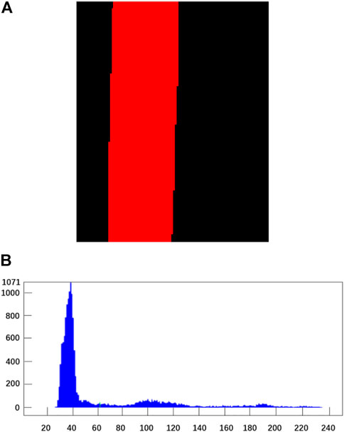
FIGURE 9. image Segmentation processing diagram of winding mould. (A) Original image. (B) Gray histogram.
Contour Extraction and angle calculation
For controlling the drafting and winding of PU filament, it is necessary to detect the included angle α and filament diameter
In the process of solving the diameter
Control of drafting and winding
Control of drafting
There are two difficulties in the preparation of PU tubes. Namely, the control of filament diameter and the control of filament winding tightness. According to the motion analysis of the drafting mechanism in the schematic diagram of tube preparation, the control of the filament diameter is closely related to the speed of the drafting roller and the extrusion amount of the metering pump. In order to simplify the control process and improve the calculation efficiency and accuracy, the method of controlling variables was adopted to make the speed difference between the solution extrusion amount and the output amount of the filament, to control the diameter of the filament. The equation of the filament diameter can be written as:
Where
In the actual drafting process, the diameter of the drafting roll
Control of winding
According to the analysis of winding motion in the schematic diagram of PU tuber preparation, the tight winding of filament on the mold was completed under the joint action of the mold rotation and the horizontal movement of filament on the moving platform. The schematic diagram of the process was shown in Figure 12A.In the figure,

FIGURE 12. Winding diagram and winding diagram. (A) Winding Diagram (Top View). (B) Reverse Winding Diagram.
According to the winding process, during the winding process, the filament was required to keep a small amount of stretching, so that the filament could closely fit the surface of the mold when it was wound on the mold. Therefore, the mold rotation speed
As the included angle was too small, the filament would wind back, as shown in Figure 12B. So, according to the actual experimental experience, the angle was controlled within 78°–88°, and the tightness between the filament coils was good. Included angle α was controlled by adjusting the moving speed
At the beginning
In the same way, due to the runout of the mold and the extrusion deformation of the filament when they were closely connected, t is smaller than
Where,
Combining Eq. 9 and Eq. 10, the controlling variable
To sum up, when the mold speed
Experimental results and analysis
Visual detection results and analysis
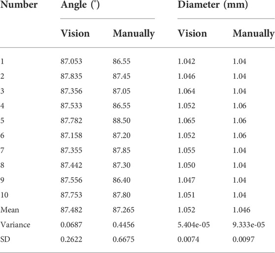
In the process of tube preparation experiment, the winding filament diameter
It could be found by analysis that the average value of the diameter error was 0.0096mm, the average value of the winding angle error is 0.4777°. The results proved the accuracy of the visual measuring method and proved it feasible to using machine vision instead of manual method to detect filament diameter and winding angle.
Performance test and analysis of finished tube
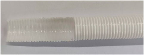
The prepared PU tube was shown in Figure 13. The inner and outer appearance of the tube were relatively uniform, without cracks, with good shape retention, indicating the filament coils were closely bonded.
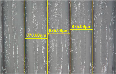
Micrograph of the prepared PU tube is shown in Figure 14. From the marked yellow dimension line, the measurement results were 870.60μm, 875.09μm and 875.09 μm respectively, which indicated the filament diameter uniformity of the winding filament was good, and the drafting process was stable. The diameters were significantly smaller compared with the filament diameters measured in Table 4, indicating the filaments were tightly extruded during the winding process, with good adhesion. And there was an obvious filler that was PU film in the gap between the filament coils, which indicated that the film-forming effect was good.
Conclusion
In this paper, a method of drawing and winding precision control for PU filament based on machine vision was proposed. This method was used to carry out the PU tube preparation experiment. The visual measurement results of the filament diameter and winding angle during the preparation process were compared with the manual measurement results and the properties of the prepared PU tube were tested and analyzed. The comparison and analyzation results proved the feasibility and accuracy of the vision measurement method and the effectiveness of the vision control method.
In the next work, we will further verify the feasibility and stability of the visual control method, try to reduce mold runout and difficulty of visual processing in terms of hardware, and improve the calculation efficiency and control accuracy.
Data availability statement
The original contributions presented in the study are included in the article/Supplementary Materials, further inquiries can be directed to the corresponding author.
Author contributions
SW and XL drafted and revised the manuscript. HY and RJ performed the experimental trials.
Funding
This project is supported by the Scientific Research Program of Department of Education of Hubei Province (Project No. Q20171609). All experiments were performed at Analytical and Testing Center, the Institute of Technology Wuhan Textile University.
Conflict of interest
The authors declare that the research was conducted in the absence of any commercial or financial relationships that could be construed as a potential conflict of interest.
Publisher’s note
All claims expressed in this article are solely those of the authors and do not necessarily represent those of their affiliated organizations, or those of the publisher, the editors and the reviewers. Any product that may be evaluated in this article, or claim that may be made by its manufacturer, is not guaranteed or endorsed by the publisher.
References
Bao, H. (2019). Discussion on development status and application trend of polymer materials. Inf. Rec. Mater. 20 (05), 4–5. doi:10.16009/j.cnki.cn13-1295/tq.2019.05.003 |
Cheng, G., and Fu, H. (2017). Advances in studies on the promotion of endothelialization by polyurethane artificial blood vessel. Peak Data Sci. 6 (3), 26–28. doi:10.19551/j.cnki.issn1672-9129.2017.05.010 |
Cheng, Z., and Zhao, Q. (2017). A brief analysis of the development status and application trend of polymer materials. Sci. Technol. Innovation Her. 14 (32), 69–70. doi:10.16660/j.cnki.1674-098X.2017.32.069 |
Christian, Z., Bergmeister, H., Stoiber, M., Schima, H., and Weigel, G. (2010). Electrospun polyurethane vascular grafts: In vitro mechanical behavior and endothelial adhesion molecule expression. J. Biomed. Mat. Res. A 93 (2), 716–723. doi:10.1002/jbm.a.32584 |
Gao, Cg, Fan, Yi, and Tong, W. (2020). Research on robot vision calibration and application based on Halcon. Mod. Electron. Technol. 43 (18), 178–181. doi:10.16652/j.issn.1004-373x.2020.18.047 |
Gao, Y., Li, J., and Tan, Hg (2014). Preparation and characterization of small diameter PU porous tubes. China Plast. Ind. 42 (5), 112121–113116. doi:10.3969/j.issn.1005-5770.2014.05.027 |
Li, L., Chen, Y., and Zbigniew, H. (2013). Boron nitride nanotube reinforced polyurethane composites. Prog. Nat. Sci. Mater. Int. 23 (2), 170–173. doi:10.1016/j.pnsc.2013.03.004 |
Li, Y., and Cao, F. (2020). Laser non-contact inspection system for metal surface roughness. Laser J. 41 (08), 35–39. doi:10.14016/j.cnki.jgzz.2020.08.035 |
Liang, H., and Huang, K. (2016). Development status and trend of biomedical polymer materials. Adv. Mater. Ind. (2), 12–15. doi:10.3969/j.issn.1008-892X.2016.02.004 |
Liu, C., and Yang, T. (2021). Application and industrial development of machine vision in intelligent manufacturing. Mach. Tool Hydraulics 49 (11), 172–178. doi:10.3969/j.issn.1001-3881.2021.11.036 |
Miyamoto, K., Sugimoto, T., Okada, M., and Maeda, S. (2002). Usefulness of polyurethane for small-caliber vascular prostheses in comparison with autologous vein graft. J. Artif. Organs 5 (2), 113–116. doi:10.1007/s100470200020 |
Pan, S., Li, S., Tang, X., Zheng, H., Wu, Y., and Tao, J. (2008). Study on implantation of small diameter polyurethane microporous vascular graft in animals. Chin. J. Biomed. Eng. 27 (3), 451–456. doi:10.3969/j.issn.0258-8021.2008.03.024 |
Qu, H. (2018). Brief discussion on the application status and development trend of polymer materials. Sci. Technol. Inf. 16 (26), 158–159. doi:10.16661/j.cnki.1672-3791.2018.26.158 |
Shaker, S., Li, C., Zhou, T., and Wang, L. (2019). The development status and trend prospect of artificial blood vessels. Tech. Text. 37 (3), 1–5. doi:10.3969/j.issn.1004-7093.2019.03.001 |
Shao, S., Wu, H., Tang, L., Li, J., Li, Z., and Tan, H. (2022). Research and application progress of medical PU materials. PU Ind. 37 (2), 1–6. doi:10.3969/j.issn.1005-1902.2022.02.001 |
Uscategui Yomaira, L., Diaz Luis, E., and Valero Manuel, F. (2018). Biomedical applications of polyurethanes. Quimica Nova 41 (4), 434–445. doi:10.21577/0100-4042.20170191 |
Wang, Z., Liu, F., Han, E., Ke, W., and Luo, S. (2009). Effect of ZnO nanoparticles on anti-aging properties of polyurethane coating. Sci. Bull. (Beijing). 54 (19), 3464–3472. doi:10.1007/s11434-009-0024-7 |
Wang, Q, Q., Lv, C., Liang, X., He, F., Zhang, R.i, and Ling, L. (2004). Study on the stress-strain curve of polyacrylonitrile fiber during drawing in water bath. New Carbon Mater. 19 (1), 38–44. doi:10.3969/j.issn.1007-8827.2004.01.008 |
Wang, Z. X, Z. X., Liu, S. Q., Guidoin, R., and Kodama, M. (2004). PU vascular grafts with thorough porositydoes an internal or an external membrane wrapping improve their in vivo blood compatibility and biofunctionality. Artif. Cells Blood Substitutes Biotechnol. 32 (3), 463–484. doi:10.1081/bio-200027524 | |
Wu, H., Duan, R., Li, L., Gong, J., Ying, L., and Xue, L. (2013). Non-contact detection method of pigs in experimental pipelines. Exp. Technol. Manag. 30 (11), 63–65+69. doi:10.16791/j.cnki.sjg.2013.11.018 |
Wu, S., Qian, T., Dong, X., and Lu, M. (2015). Research progress of PU modification. Jiangsu Build. Mater. (2), 28–31. doi:10.3969/j.issn.1004-5538.2015.02.010 |
Wu, Y., Xing, M., Wang, L., and Guan, G. (2020). Polyvinyl alcohol/polyacrylamide hydrogel-based small-bore artificial vascular material. J. Donghua Univ. Nat. Sci. 46 (1), 6074–6167. doi:10.3969/j.issn.1671-0444.2020.01.010 |
Xiao, J., He, W., and Ouyang, X. (2022). Research on rapid defect detection method of special-shaped spring based on machine vision. Mach. Tool Hydraulics. 50 (2), 99–104. doi:10.3969/j.issn.1001-3881.2022.02.019 |
Xie, Y., Sheng, Y., Qiu, M., and Gui, F. (2022). An adaptive decoding biased random key genetic algorithm for cloud workflow scheduling. Eng. Appl. Artif. Intell. 112 (2022), 104879. doi:10.1016/j.engappai.2022.104879 |
Xu, Y., Zhong, Y., Fu, Q., and Xie, X. (2012). Recent progress in polyurethane vascular grafts. J. Funct. Mater. 43, 6–9.
Yaguchi, , Funakubo, A., Okoshi, T., and Noishiki, Y. (2002). Fabrication of small-diameter polyurethane vascular grafts with microporous structure. J. Artif. Organs 5 (2), 117–122. FunakuboOkoshiNoishiki. doi:10.1007/s100470200021 |
Yao, D. (2020). Non-contact rapid detection method for verticality of large chimneys. Theor. Res. Urban Constr. (05), 40–41. doi:10.19569/j.cnki.cn119313/tu.202005035 |
Zhang, F., and Su, Z. (2012). Effects of size and surface modification of multi-walled carbon nanotubes on mechanical properties of PU-based nanocomposites. J. Wuhan Univ. Technol. Mater. Sci. 27 (4), 608–614. doi:10.1007/s11595-012-0514-3 |
Zhang, J. (2015). Preparation and evaluation of poly (ethyllactide-lactide-caprolactone) artificial blood vessel. Tian Jing: NankaiUniversity. doi:10.7666/d.Y2940123 |
Zhao, B. (2019). Research on theoretical model of spunbond polymer fiber drafting. Polyest. Ind. 32 (5), 16–20. doi:10.3969/j.issn.1008-8261.2019.05.005 |
Zhou, J. (2009). Non-contact detection method of left and right heart system and its sensor design [D]. Hangzhou Dianzi University. doi:10.7666/d.d094304 |
Keywords: PU filament, tube preparation, visual measurement, drafting control, winding control
Citation: Wu S, Yang H, Liu X and Jia R (2022) Precision control of polyurethane filament drafting and winding based on machine vision. Front. Bioeng. Biotechnol. 10:978212. doi: 10.3389/fbioe.2022.978212
Received: 25 June 2022; Accepted: 08 August 2022;
Published: 16 September 2022.
Edited by:
Zhihua Cui, Taiyuan University of Science and Technology, ChinaReviewed by:
Ahmed Elsabbagh, Ain Shams University, EgyptHu Zhu, Nanjing University of Posts and Telecommunications, China
Zhenghong Yu, Guangdong Polytechnic of Science and Technology, China
Copyright © 2022 Wu, Yang, Liu and Jia. This is an open-access article distributed under the terms of the Creative Commons Attribution License (CC BY). The use, distribution or reproduction in other forums is permitted, provided the original author(s) and the copyright owner(s) are credited and that the original publication in this journal is cited, in accordance with accepted academic practice. No use, distribution or reproduction is permitted which does not comply with these terms.
*Correspondence: Xiangyan Liu, d2hsaXV4eUB3dHUuZWR1LmNu
 Shilin Wu
 Huayu Yang2