 Xiangsheng Gao
 Yuhang Zhao
 Min Wang1
 Ziyu Liu
 Chaozong Liu
94% of researchers rate our articles as excellent or good
Learn more about the work of our research integrity team to safeguard the quality of each article we publish.
Find out more
ORIGINAL RESEARCH article
Front. Bioeng. Biotechnol., 16 May 2022
Sec. Biomaterials
Volume 10 - 2022 | https://doi.org/10.3389/fbioe.2022.850184
This article is part of the Research TopicBiological and Functional Restoration of Mechano- and Electro conductive Tissues and Organs: A Regenerative ApproachView all 11 articles
Patients who has been implanted with hip implant usually undergo revision surgery. The reason is that high stiff implants would cause non-physiological distribution loadings, which is also known as stress shielding, and finally lead to bone loss and aseptic loosening. Titanium implants are widely used in human bone tissues; however, the subsequent elastic modulus mismatch problem has become increasingly serious, and can lead to stress-shielding effects. This study aimed to develop a parametric design methodology of porous titanium alloy hip implant with gradient elastic modulus, and mitigate the stress-shielding effect. Four independent adjustable dimensions of the porous structure were parametrically designed, and the Kriging algorithm was used to establish the mapping relationship between the four adjustable dimensions and the porosity, surface-to-volume ratio, and elastic modulus. Moreover, the equivalent stress on the surface of the femur was optimized by response surface methodology, and the optimal gradient elastic modulus of the implant was obtained. Finally, through the Kriging approximation model and optimization results of the finite element method, the dimensions of each segment of the porous structure that could effectively mitigate the stress-shielding effect were determined. Experimental results demonstrated that the parameterized design method of the porous implant with gradient elastic modulus proposed in this study increased the strain value on the femoral surface by 17.1% on average. Consequently, the stress-shielding effect of the femoral tissue induced by the titanium alloy implant was effectively mitigated.
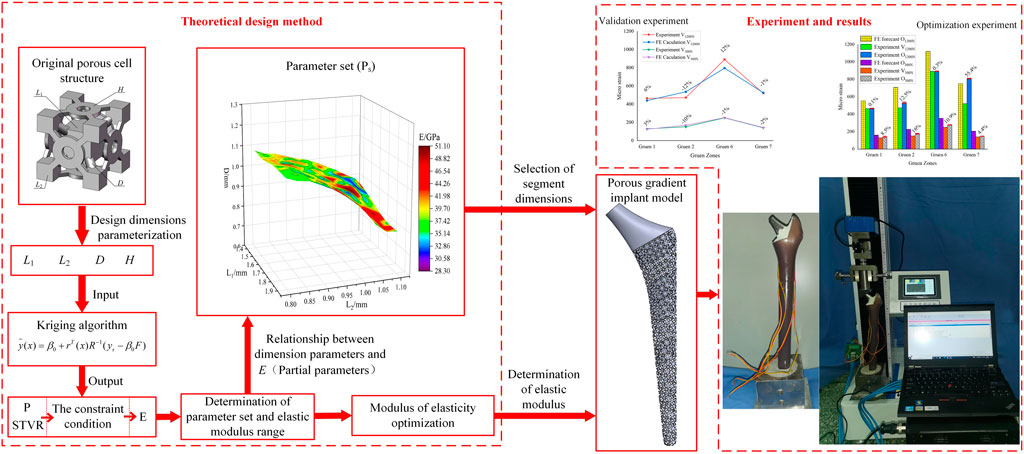
GRAPHICAL ABSTRACT
Highlights
➢ Propose a Kriging-based parametric design method for gradient porous structure.
➢ Optimize the elastic modulus based on the response surface methodology to adjust the stress distribution of femur.
➢ Develop an implant with gradient porous structure to mitigate the stress-shielding effect and verified by experiments.
Patients who has been implanted with hip implant may suffer secondary injuries after periprosthetic fracture or feeling severe painfulness. One of the reasons is that high stiff implants would cause non-physiological distribution loadings, which is also known as stress shielding, and finally lead to bone loss and aseptic loosening (Naghavi et al., 2019).
However, inserting a stiff implant into human body would result in non-physiological distribution loadings (Ahmed et al., 2020). In that case, it would cause a decrease of the periprosthetic bone strain (Huiskes et al., 1992) and then lead to bone loss and aseptic loosening (Xu and Robinson, 2008; Jeyapalina et al., 2014). Managing stress distribution would one of the main issue for implants, and the design should provide suitable strain-related stimulus for altering bone mass by bone remodeling (bone resorption or bone apposition) (Prendergast and Taylor, 1994).
In recent years, cellular metallic structures are of particular interest in orthopedic implant applications, since they can be effectively used for the replacement of broken or damaged bones (Abate et al., 2021). In all metal implant materials that can be designed for cell structure, titanium alloys are promising materials used as bone implants due to their unique properties such as high specific strength, excellent biocompatibility, and corrosion resistance (Geetha et al., 2009; Niinomi et al., 2012). Nevertheless, the elastic modulus of human bone (<30 GPa) is much lower than that of solid titanium (∼110 GPa) (Abdel-Hady Gepreel and Niinomi, 2013). The mismatch of the elastic modulus between bone tissues and solid implants causes stress shielding that can weaken the bone and stop bone growth. Previous studies have reported that this stress can be reduced by implants with porous structure, mainly by adjusting their pore size and porosity (Gibson, 2005), (Honda et al., 2013). For example, trabecular metal with a porous structure has been found in several studies to show good results in revision arthroplasty for severe acetabular bone loss (Christie, 2002; Flecher, Sporer, and Paprosky, 2008; Davies et al., 2011). Such porous structures have been proven to provide a firm fixation of the implant (Nazir et al., 2019), since they can not only reduce the elastic modulus of the titanium alloy, but also facilitate bone osseointegration (Takemoto et al., 2005; Wiria et al., 2010; Torres-Sanchez et al., 2017) and in-growth (Babaie and Bhaduri, 2018).
More specifically, the elastic modulus of a titanium alloy can be adjusted by the design of the porous structure, thereby mitigating the stress shielding effect. The elastic modulus of an implant can be custom-defined, and by controlling the porosity, the implant can obtain mechanical properties and structure similar to those of bone (Yan et al., 2015). For example, Lee et al. (2014) investigated the effect of space scaffolding on the structure and mechanical properties of porous titanium, and they concluded that porosity determines the modulus of elasticity. Mullen (Mullen et al., 2009) constructed a honeycomb titanium structure based on octahedral cells and Arabnejad (Arabnejad et al., 2016) developed two high-strength tensile dominant topologies; both exhibited the potential of such structures for orthopaedic implants. Based on newly-designed honeycomb structures and five different existing honeycomb structures, Abate et al. (2020) discussed the optimization effects of cell size, lattice topology, porosity, and honeycomb structure on mechanical properties. Their results demonstrated that the optimized honeycomb structures had much lower stress and deformation. Xu et al. (2021) investigated six composite lattice structures with different support radii consisting of simple cubic, body-centered cubic (BCC), and edge-centered cubic cells. Luxner et al. (2007) and Han et al. (2017) also suggested that BCC structures can have relatively higher porosity controllability and better mechanical properties than other structures. Among these structures, the BCC structure was found more suitable for parametric design. The excellent properties of the BCC structure had also been demonstrated experimentally by Cuadrado (Cuadrado et al., 2017).
Previous studies have assessed the actual performance of implants using porous structures within the femur. For instance, in order to reduce the stiffness and allow the inward growth of bone tissue, Jetté et al. (2018) proposed a hip implant design characterized by a porous structure based on a diamond cubic lattice. Alkhatib et al. (2019) developed finite element (FE) models of titanium alloy porous implants and effective porous implants, and verified that porosity affects the stress-shielding effect. Functional gradient materials (FGM) have gradually become the focus of the implant structure research, providing a new method for implant structure design (Moussa et al., 2020). To minimize the stress shielding effect and extend the life of implants, Sun et al. (2018) developed a FE model for bone implants and provided a general approach for designing patient-specific implants with a gradient modulus distribution. Oshkour et al. (2013) developed a functional gradient hip implant to reduce the stress shielding effect and improve the total hip replacement performance. Limmahakhun et al. (2017) assessed the possibility of using graded porous Co-Cr alloys in implants. A comparison of four shapes of femoral stems demonstrated that round implants undergo less deformation and have lower von Mises stresses (Chethan et al., 2019). In general, implants with a functional gradient structure similar to that of bone tissue are ideal for achieving the required mechanical and biological properties (Leong et al., 2008; Han et al., 2019; Chen H. et al., 2020).
In the design of hip implants with porous structure, the design methods are divided into parametric and non-parametric methods based on whether the porous structure is generated by an algorithm. In non-parametric design, most of the structures were similar, and only minor changes could be made (Chen H. et al., 2020). In parametric design, different methods were mainly used to calculate and predict certain characteristic quantities after parameterization. For instance, Ahmadi et al. (2014) proposed an analytical solution to predict the elastic modulus, Poisson’s ratio, elastic buckling limit, and yield stress of a diamond cell structure based on some specific parameters. Shi et al. (2019) parametrically designed the porous structures based on three-dimensional periodic miniaturized surface (TPMS), which have a good osseointegration effect. However, no parametric optimization of porous structures was conducted in these researches. In terms of the hip implant design, the stress distribution is uneven, the elastic modulus of implant should be adjusted with the stress distribution, so the gradient porous structures should be used in the implant design. Recently, there is a lack of effective methods and corresponding experimental analysis for the femur implant design with gradient modulus.
At present, the Kriging approximation model is widely used in the engineering field. For example, Gao et al. (2013) proposed a Kriging approximation model that can quickly and effectively estimate the dynamic characteristics of the machine tool in order to study the changes of the dynamic characteristics of the machine tool in the manufacturing space. However, it has not been fully developed and applied in the field of biomedical engineering. Therefore, a new parametric design method was proposed to mitigate the stress-shielding effect by optimizing the porous structure of gradient implants using the Kriging algorithm and FE method based on the target elastic modulus on the femoral surface in this study. The contents of this paper are arranged as follows. In Section 2, the development of the FE model of the hip implant was discussed and validation experiments were carried out; in Section 3, a Kriging model was developed to express the relationship between adjustable dimensions and STVR, porosity and elastic modulus, and from these relationships the adjustable dimensions set and the range of elastic modulus for subsequent optimization were derived. Through the FE method, optimization of the elastic modulus was carried out based on the constraint range of elastic modulus, and the optimal porous structure dimensions were determined based on the optimized elastic modulus and the adjustable dimension parameter set; in Section 4, the effects of the optimized design were analyzed and experimentally verified, and finally, in Section 5, the content of this research was summarized.
In clinical practice, the most widely used material for artificial substitute bone is titanium alloy. The aim of this research is to reduce the elastic modulus of the titanium alloy implant by properly designing its gradient porous structure, so that it can adjust the stress distribution of the femur. This way, the stress-shielding effect caused by the modulus inequality will be mitigated. Therefore, it is necessary to develop a three-dimensional solid model for the subsequent parametric design, which comprises the femoral body and the titanium alloy implant. The models used in this study were taken from the GRABCAD (Popular models, 2020), and the selected femoral model and internal implant model were displayed in Figures 1A,B, respectively.
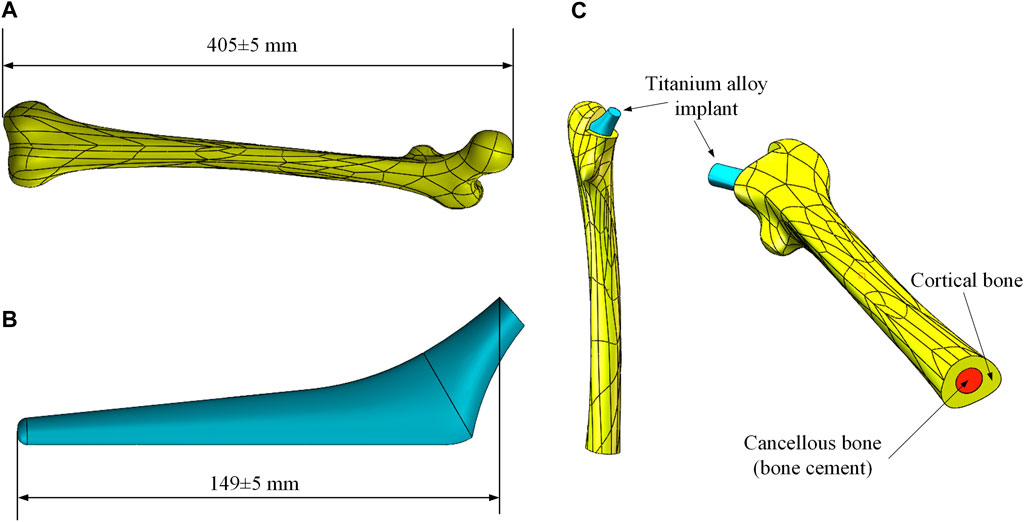
FIGURE 1. Femur and implant models. (A) Femoral model; (B) Titanium alloy implant model; (C) Combined models.
Before the development of the FE model, the excess part of the bone was excised for placing the implant and the cancellous bone. Since the elastic modulus of cancellous bone is similar to that of bone cement, the cancellous bone was replaced with bone cement in this study. Based on the shape of the femur, a solid model of bone cement was designed in the middle of its interior (The red part in Figure 1C). The final femoral model was illustrated in Figure 1C. This model was then imported into FE analysis software for static analysis. The material properties of each part of the model were listed in Table 1.
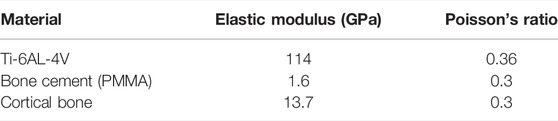
TABLE 1. Material properties of each part (Liu et al., 2019).
In this research, a binding contact was adopted. Convergence analysis was performed on the stress under different elements sizes in order to determine which element size was stable and accurate. Five different global element sizes were selected for comparison (Table 2), and the equivalent stress distribution under these sizes when the other conditions were the same was shown in Figure 2A.
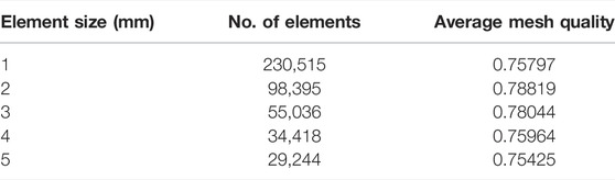
TABLE 2. Mesh properties for convergence analysis.
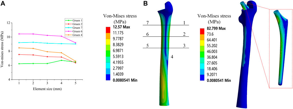
FIGURE 2. (A) Mesh convergence analysis; (B) Von Mises stress distribution and Gruen zones partition method.
Figure 2A shows the equivalent stress distribution results, where it could be observed that, when the global element size was greater than 2 mm, the equivalent stress magnitude at each position exhibited a large change. When the global element size was less than 2 mm, the change of the equivalent stress at each position became smaller and more stable. Consequently, in this study, a global element size of 2 mm was used to develop the mesh.
The load of an Asian adult male standing on one leg was considered, as referenced in previous studies (Alkhatib et al., 2019), (Farmakis et al., 2019). More specifically, a positive pressure of 1200 N was used as the main load acting on the upper end of the implant. As the most commonly used evaluation index in the field of hip implant research, and referring to previous studies (Nam et al., 2019), the equivalent stress of the seven Gruen zones on the surface of the femur were also used as the main evaluation index in this study. The contours of the average equivalent stress distribution calculated by the FE model are presented in Figure 2B.
The content of this section focuses mainly on the experimental validation of the FE model developed in Section 2.1. The materials required for the experiments include: femur, titanium alloy implant, bone cement, strain gauge, and tensile strength test machine. The femur was a composite femur purchased from the Sawbones website (Best Anatomical Medical Training Models Company, 2020) for mechanical experiments, and its mechanical properties were similar to those of human bones. The bone cement was purchased from Heraeus Medical GmbH in Germany, and the titanium alloy implants were made of Ti-6Al-4V through 3D printing.
The processed titanium alloy implant was inserted into the cavity reserved at the upper end of the femur and fixed with bone cement (Figure 3A). After the bone cement solidified, the femur was fixed in the designed base with cement, and was allowed to solidify for 48 h (Figure 3B). In the experiment, a load of 1200 N was applied by the tensile strength test machine, and the strain gauges were used to measure the micro-strain of the four Gruen zones on the outer femur surface. It should be noted that, due to the experimental conditions, the experimental values of all seven Gruen zones could not be measured in this study, so the strain was measured at four Gruen zones and the subsequent optimization process was based on the four Gruen zones used in this experiment. The positions of the four measurement Gruen zones used for simulation and experimentation were calibrated on the basis of a reference point, i.e., a reference point at the same position was selected on the model and the experimental entity, and the subsequent measurement points were calibrated on the basis of this reference point. In addition, another experiment under a load of 300 N was performed in order to compare the experimental results. The experimental loading situation was demonstrated in Figure 3C. The micro-strain of each zone under these two load conditions could be observed in the Supplementary Material. The micro-strain values measured experimentally at the four Gruen zones on the femoral surface were compared with the those calculated by the FE model; thus, the correctness of the FE model was verified based on the magnitude of the error.
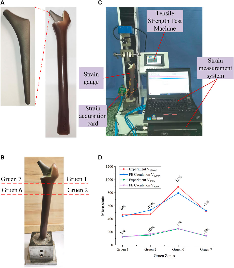
FIGURE 3. (A) Experimental processing of the bionic femur; (B) Combination and fixation of the femur and implant; (C) The process of validation experiment; (D) Comparison of validation experimental results and simulation results.
The comparison between the experimental and FE analysis results was shown in Figure 3D. Among them, V1200N and V300N represent the micro-strain values when the load was 1200 and 300 N, respectively. As it could be observed in Figure 3D, when the load was 1200 N, the maximum error was 12% and the smallest difference between the micro-strain values was in the Gruen seven zone, where the error was only -1%. In the 300 N load test, the maximum error appeared also in the Gruen 2 zone (10%), while the minimum error was found in the Gruen 6 zone. After experimental measurement and analysis, it was found that the micro-strain value in Gruen 2 was far from the FE result. This may have been caused by a number of reasons, including the lack of a reference coordinate system in the experiment, i.e., the experimental and simulation points may have not been corresponding exactly. Moreover, the relative difference between the numerical and experimental values may have also been caused by the difference between the numerical simulation and the actual boundary conditions at the femur and implant interface (Jetté et al., 2018). At the same time, the use of bone cement may have also affected the results. But in general, the error between the micro-strain values calculated by the FE model and the experimental results was small; thus, the FE model developed in this study could be considered correct and valid.
The FE model was experimentally verified in Section 2, and the parametric design of the porous structure of the implant was based on this model. In this section, the parametric design of the titanium alloy implant was mainly divided into two parts: the determination of the dimension parameter set (
In the process of parametric optimization in this section, the mapping relationship between the internal dimensions of the cellular structure and the equivalent stress on the femoral surface cannot be directly established by the FE method. Moreover, compared with the FE method, the Kriging method can also perform personalized optimization according to the constraints of the cell. Therefore, in order to improve the efficiency of optimization and realize the parametric design of porowus structures, the respective advantages of the two methods were combined for the design of implants with gradient moduli in this study. In order to express the mapping relationship between various parameters, the Kriging approximation model was developed based on the original porous cell structure, and the dimension parameter set for subsequent optimization design was determined. Specifically, the Kriging model was developed to express the relationship between adjustable dimensions and STVR, porosity and elastic modulus, and the adjustable dimensions set and the set of elastic modulus for subsequent optimization were derived from these relationships. The upper and lower limits of the adjustable dimension parameter set satisfying the conditions (Eqs 3 and 4) was used to determine the upper and lower limits of the elastic modulus to be input into the response surface optimization range settings, and then the elastic modulus was optimized by the response surface optimization provided by the FE method (Figure 4A). The optimal equivalent elastic modulus of each segment could be determined when the conditions of Eq. 2 were satisfied. The dimension parameters of each cell were determined in the adjustable dimension parameter set (
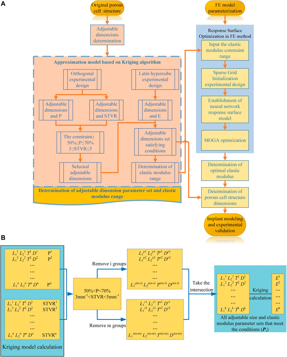
FIGURE 4. Optimization process. (A) Flowchart of the implant design and optimization process; (B) Process of parametric optimization based on Kriging model.
The general optimization algorithm is defined as follows:
The constraints are as follows:
I Porosity
II Surface-to-volume ratio
III Equivalent elastic modulus
where E, σ, and
In order to satisfy the optimization goals for the different femur positions, the solid model of the titanium alloy implant was divided into eight segments from A to H (Figure 5A). In the A segment, which was the main force-bearing part, titanium alloy entities were used. The elastic modulus of the other seven segments varied according to the optimization results. In order to simplify the optimization process and guarantee the adjustability of the structure, a BCC cell able to individually change the local dimensions was designed (Figure 5B). This type of structure is universal, and the subsequent optimization was based on this structure. By changing its internal dimensions, each segment could obtain a suitable elastic modulus.
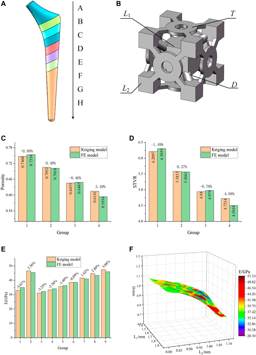
FIGURE 5. Designed porous structure and error analysis of the Kriging model. (A) Segmented implant; (B) Initial cell structure and adjustable dimensions; (C) Error of porosity calculated by the Kriging model and the FE model; (D) Error of STVR calculated by the Kriging model and the FE model; (E) Error of elastic modulus calculated by the Kriging model and the FE model; (F) Relationship between E and the three groups of dimensions in the dimension parameter set.
Considering the requirements for bone in-growth and manufacturability, Chen et al. (2020) reported that a scaffold with a porosity of 60% has the best cell proliferation and osteogenic differentiation (in vitro experiment) and bone in-growth (in vivo experiment). Jetté et al. (2018) suggested that, when designing porous structures, the porosity should be between 40 and 70%. Abate et al. (2021) showed that the cellular implants with porosity of 56 and 58% have the potential to be used in orthopedic and prosthetic applications to improve osseointegration. When using BCC structures, the porosity in the range of 50–70% can be used to design gradient porous implants so that the mechanical properties of cortical bone can be simulated (Chowdhury et al., 2021). At the same time, bone growth, migration, and cell adhesion are also affected by the surface-to-volume ratio (STVR) of the porous structure. Studies by Beaupré (Beaupre et al., 1990) and Coelho (Coelho et al., 2009) had indicated that a tight bone fixation could be provided by the implant if the STVR of their porous structure was in a range of 3–5 mm−1. Therefore, in this study, a porosity ranging within 50–70% and an STVR ranging within 3-5 mm−1 were used as constraints for the optimization of the porous cell structure dimensions. The porosity and STVR should satisfy the above constraints by changing the adjustable dimensions of the porous structure. According to the original structure in Figure 5B, the freely and independent adjustable dimensions were the side length L1 of the center cube, the side length L2 of the outer cube, the pillar diameter D, and the thickness T of the connecting plate. Therefore, only the mapping relationships between the four dimensions and P, STVR were needed in order to determine all the structural dimensions that satisfy the above constraints.
In order to determine these mapping relationship, two Kriging approximation model were developed, where the four adjustment dimensions were used as the input parameters, P and STVR were used as the output response parameters, and the genetic algorithm was used to optimize the Kriging model parameters and increase its precision. In order to develop a Kriging model, it is necessary to design orthogonal experiments for the input and output parameters. This method can make the role of each factor clear, and can pick out representative test points for experiments to find the best level matching, and can greatly reduce the number of experiments, and there is no strict limit on the number of factors. The optimization process of the Kriging model and the results of the orthogonal experiment were provided in the Supplementary Material. In this study, a total of 16 sets of experiments with four factors and four levels were used and the model was determined based on the results of the orthogonal experiments. Four groups of adjustment dimensions that were not trained by the Kriging model and completely different from those listed in the Supplementary Material were selected to compare the actual value calculated by the FE model with that predicted by this model and evaluate the accuracy of the model. The results were presented in Figures 5C,D.
As it can be observed in Figures 5C,D, the error between the results predicted by the developed Kriging model and those obtained by the FE simulation was small. Regardless of whether it was the predicted porosity or STVR, after inputting the same dimensions parameters, the maximum error between the results obtained by the Kriging model and the FE model appeared in Group 4. The reason is that when one or more of the four adjustable dimensions are too large or too small, the design deviation will increase significantly. Nevertheless, the maximum error within the dimension design range was only 4.88%, and this model could be considered accurate. All manufacturable adjustable dimensions were input into the model, and the porosity and STVR values corresponding to all manufacturable adjustable dimensions could be determined through the Kriging model. After removing the values that do not satisfy the constraints (Figure 4B), the adjustable dimensions set that satisfy the conditions could be obtained.
Similarly, the mapping relationship between the adjustable dimensions and the elastic modulus of this structure also needs to be expressed through a Kriging model. Different from the previous experimental design method, since the relationship between adjustable dimensions and elastic modulus is more complicated, the design of experiment needs to be completed with the help of FE method. After its parameterized modeling, the original porous structure was imported into the ANSYS, which was used to calculate the deformation values. The adjustment dimensions were used as the input parameters and the deformation values were used as the output parameters. Subsequently, the Latin hypercube experimental design method was used to obtain 25 groups of experiments (Supplementary Material). In order to establish the mapping relationship between the adjustment dimensions and the elastic modulus, it is necessary to convert the deformation values into the elastic modulus, as described by Eq. 6. The Kriging model between the adjustable dimensions and the elastic modulus was determined through these 25 groups of experimental data.
where E is the elastic modulus of the porous structure, F is the force acting on the porous structure, S is its cross-sectional area,
In order to verify the accuracy of this model, nine groups of untrained adjustable dimensions were selected, and the actual value calculated by the FE model was compared with that predicted by the model. The error of this model was evaluated as shown in Figure 5E, where it can be observed that the maximum error between the elastic modulus predicted by the Kriging model and that calculated by the FE model was only 5.61%; thus, this model could be considered as accurate. The previously obtained values of all the eligible adjustable dimensions were substituted into this Kriging model to calculate the elastic modulus. Therefore, the elastic modulus range used for subsequent optimization and its corresponding adjustable parameter set (
In Section 3.1, the elastic modulus range that satisfies the constraints was determined through the Kriging model. In this section, the response surface optimization of FE method was used to select from that range appropriate elastic modulus values for the implant.
After the FE model had been parameterized, the elastic modulus was set as the input value, and the equivalent stress as the output value. The response surface optimization was used to perform the final optimization design. Response surface optimization comprises mainly three parts: experimental design, approximation model development, and genetic algorithm optimization. In this study, the extremes of the elastic modulus range obtained in Section 3.1 were set as the upper and lower limits of the input values that need to be defined during the experimental design of the parameterized model. The sparse grid initialization method was used to determine the experimental samples in the experimental design, one advantage of sparse grid initialization is that it refines only in the directions necessary, so that fewer design points are needed for the same quality response surface and another is that it is effective at handling discontinuities. A neural network approximation model was developed using these samples in the response surface type selection. Multilayer perceptron neural networks is used in the neural network model inside workbench, this model works well for highly nonlinear responses and is suitable for use when the number of input parameters is high. Finally, the multi-objective genetic algorithm (MOGA) was used to optimize the elastic modulus based on the approximation model, and the maximum value of the equivalent stress on the femoral surface was taken as the target for optimization. Through the above optimization design method, the elastic modulus of the reference point used for the design of the implant and the corresponding equivalent stress value of the femoral surface were obtained.
As it can be seen in Table 3, the elastic modulus of each segment of the optimized implant was different, and the elastic modulus of Segments B and D were larger. In order to verify the effectiveness of this optimization method, the elastic modulus values listed in Table 3 were added to the FE model to perform simulations. The simulation results were compared with the equivalent stress in Table 3, and the comparison results were shown in Figure 6B. It could be observed that the difference between the equivalent stress obtained after optimization and that calculated by the actual elastic modulus was not large, and the maximum error was 4.26%, which was in line with the expectations.
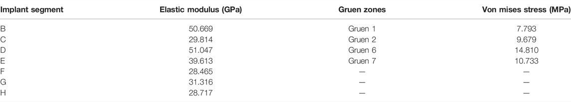
TABLE 3. Optimization results.
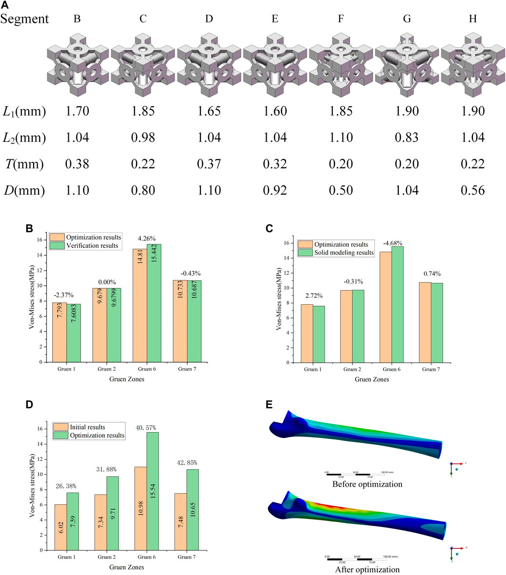
FIGURE 6. (A) Porous structure of the B-H segment; (B) Validation of optimization results; (C) Error between the optimization of the elastic modulus and the solid modeling after optimization; (D) Optimization effect analysis; (E) Equivalent stress distribution of the femur before and after optimization.
The dimensions of each part corresponding to the optimized elastic modulus in Table 3 could be found from the adjustable dimension parameter set (
It can be observed that the equivalent stress on the femoral surface calculated by the FE model was not much different from the optimized result, and the maximum error was within 5%. Consequently, the method proposed in this study to optimize the porous structure of the implant was effective, and the error produced was small. According to the comparison between optimized and initial results (Figure 6D), the equivalent stress on the femoral surface was increased by at least 26% after optimization compared to the unoptimized results. The best optimization effect was in Gruen 7, where the equivalent stress was increased by 42.8%. In addition, it could be seen from Figure 6E that compared with the equivalent stress of the femur before optimization, the equivalent stress of the femur after optimization increases significantly, and the area where the stress increases was also larger.
Through the mutual validation of the FE model, the implant with porous structure optimized by the proposed method also exhibited good results in the calculation, and the equivalent stress on the surface of the femur was improved.
In Section 3, the porous cell structures were parametrically designed and the Kriging model and FE method were used to obtain a set of dimensions parameters that satisfy the constraints (Figure 6A). After optimizing the elastic modulus, the optimal porous structure model of each segment of the titanium alloy implant was developed (Figure 7A). In order to verify the actual effect of this optimization method, the experimental analysis was performed again with full reference to the model validation experiment performed in Section 2.2. In order to ensure the validity of this optimization effect analysis experiment, 10 measurements were taken for this optimization experiment and performed statistical analysis on these 10 experiments as shown in Figure 7C. The 3D printed implant used in the experiments was presented in Figure 7B and the experimental data were provided in the Supplementary Material. The effect of the optimization results obtained by the experiment was depicted in Figure 7C.
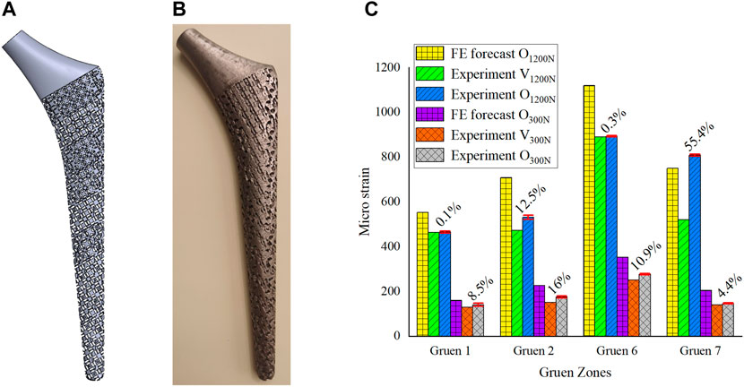
FIGURE 7. (A) 3D model of gradient porous implant; (B) The hip implant manufactured by 3D printing; (C) Analysis of the optimization effect.
In Figure 7C, V1200N is the validation experimental result before optimization (Section 2.2), O1200N is the experimental result after optimization, and there are also optimization results predicted by the FE model. The same is true for the experiment under a load of 300 N. From the statistical analysis obtained from 10 experiments in Figure 7C, it could be seen that the results of multiple experiments performed in this optimization experiment were relatively stable, and it could be observed that the experimental measurement results after optimization were better than those before optimization. The micro-strain on the femoral surface was increased by 17.1% on average under 1200 N load and by 10% on average under 300 N load. The most obvious improvement in both cases was still at Gruen 7, which was the same as the FE prediction. Under the load of 300N, the implant was firmly attached to the femur by the bone cement, and the stress stimulation on the femur was relatively uniform, so it could be seen that the micro strain on the femoral surface increased more evenly. However, at a load of 1200 N, due to the high load applied to the implant, the force state between the implant and the femur is similar to that of a lever, i.e. Gruen 2, the support point, and Gruen 7, the stress point, are the main load-bearing areas, while Zones 1 and 6 are unstressed or less stressed, which results in a non-uniform growth of micro strain on the femoral surface as shown in Figure 7. In addition, due to some of the reasons mentioned in Section 2.2 and the manufacturing errors of 3D printed porous implants, the experimental results were generally inferior to the FE simulation ones.
In this paper, a new parametric design method was proposed to mitigate the stress-shielding effect by optimizing the gradient porous structure of implants. A FE model of a hip implant for elastic modulus optimization was developed and validated experimentally. The porous structure was parametrically designed, the mapping relationship between the adjustable dimensions and porosity, STVR, and elastic modulus was established, and the adjustable dimensions set and the set of elastic modulus for subsequent optimization were derived from these relationships. These parameter sets calculated by the Kriging model were used as the constraints for the subsequent optimization of input and output parameters. By combining the results calculated by the kriging model, an optimal implant with porous structure and gradient elastic modulus was designed by the FE method. The experimental results demonstrated that the femoral surface micro-strain was increased by 17.1% and 10% on average compared with the unoptimized results. Consequently, it can be concluded that the parametric optimization design method proposed in this paper was effective and could substantially mitigate the stress-shielding effect by reducing the elastic modulus of the implant. The parametric design method proposed in this research is based on a general structure, the local dimensions of which can change individually; thus, this method is suitable for various situations where the elastic modulus needs to be adjusted through porous structure parametric design. In the future, the method of parametric design in this paper will be used to study the differentiation of the porous structure of implants in femurs of different ages.
The original contributions presented in the study are included in the article/Supplementary Material, further inquiries can be directed to the corresponding authors.
All authors listed have made a substantial, direct, and intellectual contribution to the work and approved it for publication. XG conceived the modeling and analysis, and wrote the manuscript as well. YZ and XG conducted the experiment and modeling. MW conducted the data analysis. CL and ZL supervised this work and revised the manuscript.
The author(s) disclosed receipt of the following financial support for the research, authorship, and/or publication of this article: This study was supported by the National Natural Science Foundation of China (grant numbers: 51875008, 51505012, and 51575014), Royal Society via an International Exchange Programme (Grant No: IEC\NSFC\191253), International Research Cooperation Seed Fund of Beijing University of Technology (grant number: 2021A10), European Commission via a H2020-MSCA-RISE programme (BAMOS, Grant No: 734156), Innovative UK via Newton Fund (Grant No:102872) and Engineering and Physical Science Research Council (EPSRC) via DTP CASE programme (Grant No:EP/T517793/1).
The authors declare that the research was conducted in the absence of any commercial or financial relationships that could be construed as a potential conflict of interest.
All claims expressed in this article are solely those of the authors and do not necessarily represent those of their affiliated organizations, or those of the publisher, the editors and the reviewers. Any product that may be evaluated in this article, or claim that may be made by its manufacturer, is not guaranteed or endorsed by the publisher.
This is a short text to acknowledge the contributions of specific colleagues, institutions, or agencies that aided the efforts of the authors.
The Supplementary Material for this article can be found online at: https://www.frontiersin.org/articles/10.3389/fbioe.2022.850184/full#supplementary-material
Abate, K. M., Nazir, A., and Jeng, J.-Y. (2021). Design, Optimization, and Selective Laser Melting of Vin Tiles Cellular Structure-Based Hip Implant. Int. J. Adv. Manuf Technol. 112, 2037–2050. doi:10.1007/s00170-020-06323-5
Abate, K. M., Nazir, A., Yeh, Y.-P., Chen, J.-E., and Jeng, J.-Y. (2020). Design, Optimization, and Validation of Mechanical Properties of Different Cellular Structures for Biomedical Application. Int. J. Adv. Manuf Technol. 106, 1253–1265. doi:10.1007/s00170-019-04671-5
Abdel-Hady Gepreel, M., and Niinomi, M. (2013). Biocompatibility of Ti-Alloys for Long-Term Implantation. J. Mech. Behav. Biomed. Mater. 20, 407–415. doi:10.1016/j.jmbbm.2012.11.014
Ahmadi, S. M., Campoli, G., Amin Yavari, S., Sajadi, B., Wauthle, R., Schrooten, J., et al. (2014). Mechanical Behavior of Regular Open-Cell Porous Biomaterials Made of Diamond Lattice Unit Cells. J. Mech. Behav. Biomed. Mater. 34, 106–115. doi:10.1016/j.jmbbm.2014.02.003
Ahmed, K., Greene, R. J., Aston, W., Briggs, T., Pendegrass, C., Moazen, M., et al. (2020). Experimental Validation of an ITAP Numerical Model and the Effect of Implant Stem Stiffness on Bone Strain Energy. Ann. Biomed. Eng. 48, 1382–1395. doi:10.1007/s10439-020-02456-6
Alkhatib, S. E., Mehboob, H., and Tarlochan, F. (2019). Finite Element Analysis of Porous Titanium Alloy Hip Stem to Evaluate the Biomechanical Performance During Walking and Stair Climbing. J. Bionic Eng. 16, 1103–1115. doi:10.1007/s42235-019-0122-4
Arabnejad, S., Burnett Johnston, R., Pura, J. A., Singh, B., Tanzer, M., and Pasini, D. (2016). High-Strength Porous Biomaterials for Bone Replacement: A Strategy to Assess the Interplay Between Cell Morphology, Mechanical Properties, Bone Ingrowth and Manufacturing Constraints. Acta Biomater. 30, 345–356. doi:10.1016/j.actbio.2015.10.048
Babaie, E., and Bhaduri, S. B. (2018). Fabrication Aspects of Porous Biomaterials in Orthopedic Applications: A Review. ACS Biomater. Sci. Eng. 4, 1–39. doi:10.1021/acsbiomaterials.7b00615
Beaupré, G. S., Orr, T. E., and Carter, D. R. (1990). An Approach for Time-Dependent Bone Modeling and Remodeling-Theoretical Development. J. Orthop. Res. 8 (5), 651–661. doi:10.1002/jor.1100080506
Best Anatomical Medical Training Models Company (2020). Sawbones Is the Leader in Medical Training Models for Orthopedic and Medical Education. Sawbones Available at: https://www.sawbones.com/.
Chen, H., Han, Q., Wang, C., Liu, Y., Chen, B., and Wang, J. (2020a). Porous Scaffold Design for Additive Manufacturing in Orthopedics: A Review. Front. Bioeng. Biotechnol. 8, 609. doi:10.3389/fbioe.2020.00609
Chen, Z., Yan, X., Yin, S., Liu, L., Liu, X., Zhao, G., et al. (2020b). Influence of the Pore Size and Porosity of Selective Laser Melted Ti6Al4V ELI Porous Scaffold on Cell Proliferation, Osteogenesis and Bone Ingrowth. Mater. Sci. Eng. C 106, 110289. doi:10.1016/j.msec.2019.110289
Chethan, K. N., Shyamasunder Bhat, N., Zuber, M., and Satish Shenoy, B. (2019). Finite Element Analysis of Different Hip Implant Designs Along with Femur Under Static Loading Conditions. J. Biomed. Phys. Eng. 9, 507–516. doi:10.31661/jbpe.v0i0.1210
Chowdhury, S., Anand, A., Singh, A., and Pal, B. (2021). Evaluation of Mechanical Properties of Ti-25Nb BCC Porous Cell Structure and Their Association with Structure Porosity: A Combined Finite Element Analysis and Analytical Approach for Orthopedic Application. Proc. Inst. Mech. Eng. H 235, 827–837. doi:10.1177/09544119211011309
Christie, M. J. (2002). Clinical Applications of Trabecular Metal. Am. J. Orthop. (Belle Mead. Nj) 31, 219–220. Available at: http://europepmc.org/abstract/MED/12008854.
Coelho, P. G., Fernandes, P. R., Rodrigues, H. C., Cardoso, J. B., and Guedes, J. M. (2009). Numerical Modeling of Bone Tissue Adaptation-A Hierarchical Approach for Bone Apparent Density and Trabecular Structure. J. Biomech. 42, 830–837. doi:10.1016/j.jbiomech.2009.01.020
Cuadrado, A., Yánez, A., Martel, O., Deviaene, S., and Monopoli, D. (2017). Influence of Load Orientation and of Types of Loads on the Mechanical Properties of Porous Ti6Al4V Biomaterials. Mater. Des. 135, 309–318. doi:10.1016/j.matdes.2017.09.045
Davies, J. H., Laflamme, G. Y., Delisle, J., and Fernandes, J. (2011). Trabecular Metal Used for Major Bone Loss in Acetabular Hip Revision. The J. Arthroplasty 26, 1245–1250. doi:10.1016/j.arth.2011.02.022
Farmakis, I.-I. K., Potsika, V. T., Smyris, A.-F., Gelalis, I. D., Fotiadis, D. I., and Pakos, E. E. (2019). A Biomechanical Study of the Effect of Weight Loading Conditions on the Mechanical Environment of the Hip Joint Endoprosthesis. Clin. Biomech. 70, 197–202. doi:10.1016/j.clinbiomech.2019.10.002
Flecher, X., Sporer, S., and Paprosky, W. (2008). Management of Severe Bone Loss in Acetabular Revision Using a Trabecular Metal Shell. J. Arthroplasty 23, 949–955. doi:10.1016/j.arth.2007.08.019
Gao, X.-s., Zhang, Y.-d., Gao, H.-d., and Gao, H.-w. (2013). Dynamic Characteristic Analysis of Whole Machine Tools Based on Kriging Model. J. Cent. South. Univ. 20, 3094–3102. doi:10.1007/s11771-013-1833-z
Geetha, M., Singh, A. K., Asokamani, R., and Gogia, A. K. (2009). Ti Based Biomaterials, the Ultimate Choice for Orthopaedic Implants - A Review. Prog. Mater. Sci. 54, 397–425. doi:10.1016/j.pmatsci.2008.06.004
Gibson, L. J. (2005). Biomechanics of Cellular Solids. J. Biomech. 38, 377–399. doi:10.1016/j.jbiomech.2004.09.027
Han, C., Yan, C., Wen, S., Xu, T., Li, S., Liu, J., et al. (2017). Effects of the Unit Cell Topology on the Compression Properties of Porous Co-Cr Scaffolds Fabricated via Selective Laser Melting. Rpj 23, 16–27. doi:10.1108/RPJ-08-2015-0114
Han, Q., Wang, C., Chen, H., Zhao, X., and Wang, J. (2019). Porous Tantalum and Titanium in Orthopedics: A Review. ACS Biomater. Sci. Eng. 5, 5798–5824. doi:10.1021/acsbiomaterials.9b00493
Honda, T., Katano, Y., Kuzuya, T., Hayashi, K., Ishigami, M., Itoh, A., et al. (2013). Comparison of the Efficacy of Ribavirin Plus Peginterferon Alfa-2b for Chronic Hepatitis C Infection in Patients with and without Coagulation Disorders. J. Med. Virol. 85, 228–234. doi:10.1002/jmv.23444
Huiskes, R., Weinans, H., and Rietbergen, B. V. (1992). The Relationship Between Stress Shielding and Bone Resorption Around Total Hip Stems and the Effects of Flexible Materials. Clin. Orthopaedics Relat. Res. 274, 124–134. doi:10.1097/00003086-199201000-00014
Jetté, B., Brailovski, V., Dumas, M., Simoneau, C., and Terriault, P. (2018). Femoral Stem Incorporating a Diamond Cubic Lattice Structure: Design, Manufacture and Testing. J. Mech. Behav. Biomed. Mater. 77, 58–72. doi:10.1016/j.jmbbm.2017.08.034
Jeyapalina, S., Beck, P. J., Bloebaum, R. D., and Bachus, K. N. (2014). Progression of Bone Ingrowth and Attachment Strength for Stability of Percutaneous Osseointegrated Prostheses. Clin. Orthopaedics Relat. Research® 472, 2957–2965. doi:10.1007/s11999-013-3381-0
Lee, B., Lee, T., Lee, Y., Lee, D. J., Jeong, J., Yuh, J., et al. (2014). Space-Holder Effect on Designing Pore Structure and Determining Mechanical Properties in Porous Titanium. Mater. Des. 57, 712–718. doi:10.1016/j.matdes.2013.12.078
Leong, K., Chua, C., Sudarmadji, N., and Yeong, W. (2008). Engineering Functionally Graded Tissue Engineering Scaffolds. J. Mech. Behav. Biomed. Mater. 1, 140–152. doi:10.1016/j.jmbbm.2007.11.002
Limmahakhun, S., Oloyede, A., Chantarapanich, N., Jiamwatthanachai, P., Sitthiseripratip, K., Xiao, Y., et al. (2017). Alternative Designs of Load−Sharing Cobalt Chromium Graded Femoral Stems. Mater. Today Commun. 12, 1–10. doi:10.1016/j.mtcomm.2017.05.002
Liu, T. S., Gao, R., Wei, T., and Sun, H. Q. (2019). Three-Dimensional Finite Element Analysis of the Stress Distribution of Bone Tissue Around Porous Titanium Implant. Zhonghua Kou Qiang Yi Xue Za Zhi 54, 35–40. doi:10.3760/cma.j.issn.1002-0098.2019.01.007
Luxner, M. H., Stampfl, J., and Pettermann, H. E. (2007). Numerical Simulations of 3D Open Cell Structures - Influence of Structural Irregularities on Elasto-Plasticity and Deformation Localization. Int. J. Sol. Structures 44, 2990–3003. doi:10.1016/j.ijsolstr.2006.08.039
Moussa, A., Rahman, S., Xu, M., Tanzer, M., and Pasini, D. (2020). Topology Optimization of 3D-Printed Structurally Porous Cage for Acetabular Reinforcement in Total Hip Arthroplasty. J. Mech. Behav. Biomed. Mater. 105, 103705. doi:10.1016/j.jmbbm.2020.103705
Mullen, L., Stamp, R. C., Brooks, W. K., Jones, E., and Sutcliffe, C. J. (2009). Selective Laser Melting: A Regular Unit Cell Approach for the Manufacture of Porous, Titanium, Bone In‐Growth Constructs, Suitable for Orthopedic Applications. J. Biomed. Mater. Res. 89B, 325–334. doi:10.1002/jbm.b.31219
Naghavi, S. A., Hua, J., Moazen, M., Taylor, S., and Liu, C. (2019). On the FE Modelling of Short-Stem Porous Hip Implant Design for Preventing Stress Shielding & Promoting Osseointegration 2nd International Conference on Biomaterials, Bio-Design and Manufacturing.
Nam, D., Salih, R., Barrack, R. L., and Nunley, R. M. (2019). An Evaluation of Proximal Femur Bone Density in Young, Active Patients Undergoing Total Hip Arthroplasty at One Year Postoperatively. HIP Int. 29, 51–57. doi:10.1177/1120700018761152
Nazir, A., Abate, K. M., Kumar, A., and Jeng, J.-Y. (2019). A State-Of-The-Art Review on Types, Design, Optimization, and Additive Manufacturing of Cellular Structures. Int. J. Adv. Manuf. Technol. 104, 3489–3510. doi:10.1007/s00170-019-04085-3
Niinomi, M., Nakai, M., and Hieda, J. (2012). Development of New Metallic Alloys for Biomedical Applications. Acta Biomater. 8, 3888–3903. doi:10.1016/j.actbio.2012.06.037
Oshkour, A. A., A Abu Osman, N., Davoodi, M. M., Yau, Y. H., Tarlochan, F., B Wan Abas, W. A., et al. (2013). Finite Element Analysis on Longitudinal and Radial Functionally Graded Femoral Prosthesis. Int. J. Numer. Meth. Biomed. Engng. 29 (12), 1412–1427. doi:10.1002/cnm.2583
Popular models (2020). 3D CAD Model Collection. GrabCAD Community Library. Available at: https://grabcad.com/dashboard.
Prendergast, P. J., and Taylor, D. (1994). Prediction of Bone Adaptation Using Damage Accumulation. J. Biomech. 27, 1067–1076. doi:10.1016/0021-9290(94)90223-2
Shi, J., Liang, H., Jiang, J., Tang, W., and Yang, J. (20192019). Design and Performance Evaluation of Porous Titanium alloy Structures for Bone Implantation. Math. Probl. Eng. 2019, 1–9. doi:10.1155/2019/5268280
Sun, C., Wang, L., Kang, J., Li, D., and Jin, Z. (2018). Biomechanical Optimization of Elastic Modulus Distribution in Porous Femoral Stem for Artificial Hip Joints. J. Bionic Eng. 15, 693–702. doi:10.1007/s42235-018-0057-1
Takemoto, M., Fujibayashi, S., Neo, M., Suzuki, J., Kokubo, T., and Nakamura, T. (2005). Mechanical Properties and Osteoconductivity of Porous Bioactive Titanium. Biomaterials 26, 6014–6023. doi:10.1016/j.biomaterials.2005.03.019
Torres-Sanchez, C., Al Mushref, F. R. A., Norrito, M., Yendall, K., Liu, Y., and Conway, P. P. (2017). The Effect of Pore Size and Porosity on Mechanical Properties and Biological Response of Porous Titanium Scaffolds. Mater. Sci. Eng. C 77, 219–228. doi:10.1016/j.msec.2017.03.249
Wiria, F. E., Shyan, J. Y. M., Lim, P. N., Wen, F. G. C., Yeo, J. F., and Cao, T. (2010). Printing of Titanium Implant Prototype. Mater. Des. 31, S101–S105. doi:10.1016/j.matdes.2009.12.050
Xu, W., and Robinson, K. (2008). X-Ray Image Review of the Bone Remodeling Around an Osseointegrated Trans-Femoral Implant and a Finite Element Simulation Case Study. Ann. Biomed. Eng. 36, 435–443. doi:10.1007/s10439-007-9430-7
Xu, W., Yu, A., Lu, X., Tamaddon, M., Wang, M., Zhang, J., et al. (2021). Design and Performance Evaluation of Additively Manufactured Composite Lattice Structures of Commercially Pure Ti (CP-Ti). Bioactive Mater. 6, 1215–1222. doi:10.1016/j.bioactmat.2020.10.005
Keywords: hip implant, stress-shielding, kriging algorithm, gradient porous structure, parametric design
Citation: Gao X, Zhao Y, Wang M, Liu Z and Liu C (2022) Parametric Design of Hip Implant With Gradient Porous Structure. Front. Bioeng. Biotechnol. 10:850184. doi: 10.3389/fbioe.2022.850184
Received: 07 January 2022; Accepted: 11 April 2022;
Published: 16 May 2022.
Edited by:
Yun Qian, Shanghai Jiao Tong University, ChinaReviewed by:
Yuting Lv, Shandong University of Science and Technology, ChinaCopyright © 2022 Gao, Zhao, Wang, Liu and Liu. This is an open-access article distributed under the terms of the Creative Commons Attribution License (CC BY). The use, distribution or reproduction in other forums is permitted, provided the original author(s) and the copyright owner(s) are credited and that the original publication in this journal is cited, in accordance with accepted academic practice. No use, distribution or reproduction is permitted which does not comply with these terms.
*Correspondence: Ziyu Liu, bGl1X3ppeXVAYnVhYS5lZHUuY24=; Chaozong Liu, Y2hhb3pvbmcubGl1QHVjbC5hYy51aw==
Disclaimer: All claims expressed in this article are solely those of the authors and do not necessarily represent those of their affiliated organizations, or those of the publisher, the editors and the reviewers. Any product that may be evaluated in this article or claim that may be made by its manufacturer is not guaranteed or endorsed by the publisher.
Research integrity at Frontiers
Learn more about the work of our research integrity team to safeguard the quality of each article we publish.