 Kyungbae Kim
 Candace K. Chan
95% of researchers rate our articles as excellent or good
Learn more about the work of our research integrity team to safeguard the quality of each article we publish.
Find out more
ORIGINAL RESEARCH article
Front. Batter. Electrochem. , 06 March 2024
Sec. Battery Systems and Applications
Volume 3 - 2024 | https://doi.org/10.3389/fbael.2024.1371167
This article is part of the Research Topic Women in Battery Science and Technology View all 13 articles
Understanding mechanical failure modes of Li-ion battery electrodes of varying sizes and capacities is crucially important for the development of mechanically robust and high energy density flexible lithium-ion batteries (FLIBs). Three types of pouch cells (nominal capacities of 15, 25, and 50 mAh) were examined to understand how various design features used in the cells affected their mechanical failure modes and electrochemical performance after repeated introduction of compression and tension during bending. Postmortem microstructure analysis was carried out to identify the impacts of repeated flexing; several failure modes such as crack propagation, particle detachment, composite delamination, separator damage, electrode tears, and micro-short circuits were observed. We find that the observed mechanical failure modes are mainly dependent on the: 1) size and shape of the electrode composite materials, 2) configuration of the components within the cell (e.g., method of electrode folding, location of welded tabs), and 3) orientation of the long axis of the cell with respect to the bending axis. It was observed that the discharge capacity for all cell types studied herein was only slightly decreased (∼6–7% at 2C-rate) even after 3,000 repeated bends at a 25 mm radius of curvature provided if the bending axis is aligned to the long dimension of the cell. The results of this study provide valuable information on possible failure modes in Li-ion battery electrodes subjected to repeated flexing and how they can be mitigated to improve the dependability of practical pouch cells for FLIBs.
In recent years, the demand for flexible lithium-ion batteries (FLIBs) has grown with the increasing popularity of flexible devices such as foldable smartphones and wearable accessories (Lee et al., 2013; Chen et al., 2021; Jeong et al., 2022). This trend is primarily driven by the development of foldable or flexible technologies, including cell phones, watches, and Internet of Things (IoT)-enabled electronics (Mokhtari et al., 2020; Woo et al., 2020; Lee et al., 2022). These batteries must meet the high energy density requirements while retaining mechanical flexibility to keep pace with the needs of such devices. However, the use of conventional rigid batteries still hinders this development due to their mechanical property limitations and safety issues (Harris et al., 2017; Zhu et al., 2020; Chen et al., 2021; Wehner et al., 2021; Bates et al., 2022).
Of the three main types of conventional rigid LIBs available to use in small portable devices (pouch, cylindrical, and coin cells) (Divakaran et al., 2021), the flexibility and conformability of pouch-type LIBs make them a common choice for use in flexible devices. Pouch cells are packaged with laminates comprising a heat-sealable polymer inner layer, a metallized layer such as Al, and a protective polymer outer layer. The use of multiple layers is advantageous for encapsulating the electrodes and separators while also achieving the desired macroscopic shape of the cell and maintaining good mechanical durability (Mackanic et al., 2020). However, despite the inherent flexibility of pouch cells, there are still limitations for their application as flexible batteries due to several reasons. First, the appropriate thickness for both electrode films and current collectors needs to be established, to ensure they can withstand flexing (Zhou et al., 2015; Kuang et al., 2019; Wang et al., 2021; Wu et al., 2021; Zhang et al., 2021; Li et al., 2022). To increase the electrode areal capacity, casting of thick slurry films or stacking multiple electrodes may be needed. However, use of thick electrodes can generate a large strain between the top surface and bulk structure of the electrode film during flexing (Zheng et al., 2012; Ebner et al., 2013; Ji et al., 2021), leading to the inevitable detachment or delamination of electrode materials from the current collectors. Second, the physical properties of other components of the pouch cell, such as the welded metal tabs or seal of the packaging, should be considered to improve the mechanical flexibility and durability of the cells (Jansen et al., 2002; Mackanic et al., 2020; Jia et al., 2021). Though these components play a crucial role in the electrical connections and hermetic sealing of the packaging material, they are often overlooked. In particular, the welded region where the current collector and metal tab meet the seal of the packaging is typically thicker than the stack of the electrodes inside the pouch cell.
There are several additional factors that influence the flexibility of electrodes. Conventional current collectors present a challenge in flexible batteries due to poor adhesion between the metal foil and electrode, which can cause detachment of the electrode film during repeated bending or twisting. For this reason, many studies have demonstrated free-standing electrodes or flexible current collectors for flexible batteries (Cheng et al., 2013; Song et al., 2014; Gaikwad et al., 2015; Park et al., 2017; Qian et al., 2018; Kim et al., 2023). Furthermore, the separators and packaging materials have different mechanical properties than the electrodes, which can decrease the mechanical flexibility of the pouch cell and cause surface and interfacial cracks and breakage (Yu et al., 2021; Liu et al., 2022). This type of damage can lead to unforeseen side reactions between the electrode and electrolyte, which can result in swelling, gas buildup, and thermal runaway, ultimately leading to safety failures.
We note that very few published studies focus on characterizing the failure modes induced by repeated flexing or bending of pouch cells. Most studies (Blake et al., 2016; Li et al., 2019; Galos et al., 2020; Lall et al., 2020; Ge et al., 2022) concentrate on showcasing the bending abilities of batteries without focusing on the detailed mechanical failure modes of the key components of the pouch cell. However, to improve the performance of flexible batteries, it is crucial to detect and address any potential failure modes in the bent components of the pouch cell. To fill this knowledge gap, this article delves into the study of mechanical failure modes caused by repeated flexing of ultrathin pouch cells made from conventional components, with the aim to understand the impacts of cell design on the electrochemical performance of the cells. This study involves three types of commercially available ultrathin lithium polymer batteries with nominal capacities of 15, 25, and 50 mAh. The three pouch cells are constructed with similar designs, where one single-sided coated electrode is folded over a double-sided coated electrode, with a single membrane separator in between the electrodes. In this work, we subject the pouch cells to different orientations of repeated flexing followed by electrochemical cycling and postmortem microstructural characterization. Through comparison of the microstructures of bent and electrochemically cycled cell components (i.e., cathode, anode, and separator), we find that the observed mechanical failure modes are mainly dependent on the: 1) size and shape of the electrode composite materials, 2) configuration of the components within the cell (e.g., method of electrode folding, location of welded tabs), and 3) orientation of the long axis of the cell with respect to the bending axis. The findings from this experimental research will provide valuable insights into the design of more reliable practical pouch cells for FLIBs.
All of the ultrathin lithium polymer pouch cells investigated herein were purchased from PowerStream Technology. It should be noted that PowerStream Technology was neither involved in nor has authority over this study. The chosen cells had nominal capacities at 1°C of 15 (PGEB0054018), 25 (PGEB042255), and 50 mAh (PGEB0083559) and varying rectangular shapes and sizes, which are reported in Table 1.
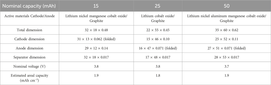
TABLE 1. Specifications of ultrathin pouch cells investigated in this study. The dimensions are written as width × length × thickness in units of millimeters; the dimensions of the single-sided electrodes when folded are reported. The estimated areal capacity was determined from the measured capacity and the cathode area (for double-sided cathodes, the areal capacity refers to the capacity of one side only).
The cells were mounted on a polycarbonate sheet (Lexan, Grainger, thickness: 20 mil = 508 µm), which was used as a substrate to support the cells during the bending tests. We opted to use Lexan as the flexing substrate because of its exceptional ability to withstand fracturing even after several thousand cycles of repeated bending. Each Lexan-supported ultrathin pouch cell was subjected to 3,000 flexing cycles using a bending machine (H-Sky Tech Ltd., Hong Kong) with the radius of curvature fixed at 25 mm (i.e., bending diameter of 50 mm). The cells were repeatedly bent back and forth at a rate of 60 times min−1, with a 0.5 s pause at the planar (i.e., not bent) and fully bent positions. Each type of pouch cell was subjected to bending in two orientations, horizontal and vertical (more details in Figure 1 and corresponding description), and each condition was performed on three different cells of the same type. Post-bending microscopy was performed on the component surfaces that were facing away from the Lexan support.
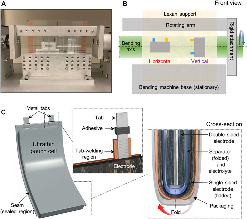
FIGURE 1. (A) Photograph of the front view of the bending machine with samples supported on a Lexan sheet. (B) Schematic illustration for the two bending orientations used in this study, where the tabs of the pouch cell are positioned perpendicular or parallel to the bending axes, which are labeled as horizontal and vertical bending. (C) Schematic illustration of the ultrathin pouch cell configuration, tab-welding region, and cell cross-section for cells investigated in this study.
Charge-discharge cycles were performed using a battery cycler (CT20001A Landt Instruments) between 4.2 and 3.0 V. Galvanostatic charging was performed using a C/10 rate until the cell voltage reached 4.2 V, at which point constant voltage charging was performed until the estimated C/50 current was achieved; discharge was carried out galvanostatically at various currents from C/10 to 2C. Prior to the bending tests, electrochemical cycling (“pre-flex cycling”) was carried out to check the capacity of each pouch cell. Three cycles of pre-flex cycling were performed with charge and discharge rates of C/10. The cells designated “as-received” were then subjected to further cycling at different C-rates starting with discharge at C/10. The other pouch cells were mechanically flexed in the fully discharged state as described in Sec. 2.2 after pre-flex cycling. After mechanical flexing, these cells were then electrochemically cycled in the same manner as described for the “as-received” cells. The capacity measured at 1C (discharge) was taken to be the nominal capacity of an individual pouch cell. The average discharge capacity of three pouch cells for each condition and the standard error were calculated, and the percentage of capacity retained was determined with respect to the capacity measured during pre-flex cycling. All the electrochemical measurements were performed at room temperature.
Microstructure analysis was carried out on the cells to study the effect of repeated flexing on the microstructure of the electrodes. Once the bending tests and electrochemical cycling were complete, the pouch cells were moved to an Ar-filled glovebox with O2 and H2O levels <0.1 ppm. The cells were then disassembled, and the electrode and separator components were washed multiple times with dimethyl carbonate to remove the electrolyte prior to the postmortem microscopy observations. The components were examined with optical microscopy (OM, Nikon LV100D) and scanning electron microscopy (SEM, Zeiss Auriga) with energy dispersive X-ray spectroscopy (EDS). A digital electronic micrometer (Mitutoyo Micrometer Series 293-340-30) was used to determine the thickness of the disassembled cell components. The dimensions of the cell components were also measured.
When conducting a flexing test on a pouch cell, it is important to ensure that the bending angle and position of the pouch with respect to the bending axis are consistent. This is because the cell will experience different levels of stress depending on where the cell components are arranged with respect to the bending axis. Another detail to consider is the part of the pouch where the tabs (terminals) extend from the laminate packaging. Usually, tabs are made of thin metal strips a few mm in width that are ultrasonically welded onto the current collectors; the welded region is generally thicker and less flexible than other parts. The ends of the tabs are also typically sandwiched on either side with a heat sealable adhesive that improves bonding to the packaging at the region where the tabs extend out of the pouch. Generally, this region is a potential site for catastrophic failure (e.g., due to tabs breaking, laminate seal failure, electrolyte leakage, etc.) even in LIBs that are not flexed, but the orientation of the tabs with respect to the main bending axis can play a major role on the integrity of the cells used for FLIBs. Therefore, it was important in this study to carry out the bending tests in a systematic and reproducible manner.
The bending machine used in this study contains a rotating arm and a stationary base (Figures 1A, B). To maintain consistency, the Lexan-supported pouch cells were secured in between aluminum plates, which are attached to the rotating arm at the top and the stationary base at the bottom. Because our goal in this study was to observe less obvious failure modes in the batteries, we intentionally chose to avoid placing the tabs directly in the region that experiences the most stress (i.e., the bending axis) during repeated flexing. We instead positioned the cells in two different orientations, horizontally and vertically, so that the bending axis would pass through the center of the cells. Figures 1A, B illustrates the front view of the bending machine with pouch cells mounted in two different orientations, where “horizontal” means the welded tabs are positioned perpendicular to the bending axis, while the tabs are parallel to the bending axis in the “vertical” orientation. The length subjected to bending was found to be approximately 26 mm (i.e., 13 mm on each side of the bending axis). Schematics of the side view (Supplementary Figure S1), more details about the bending test, and a description of the methodology for determining the bending radius of curvature and length subjected to bending are found in the Supplementary Material. When subjected to repeated cycles with a small bending radius (e.g., less than 10 mm), we found that the Lexan sheet exhibits a tendency to crack because of its stiffness. Therefore, a bending radius of 25 mm was the condition used in this study, which is a typical requirement for flexible batteries used in roll-up displays and bendable phones (Chang et al., 2020). We found that subjecting the cells to 3,000 back and forth bending cycles at a 25 mm bending radius was able to cause mechanical failure and allow for observation of the failure modes. Indeed, almost all of the cells displayed evidence of swelling from gas generation (Supplementary Figure S2); typically, this was observed after bending was completed, but did not appear to hinder the ability of the cells to be electrochemically cycled.
The ultrathin pouch cells investigated in this study were constructed using typical pouch cell designs, with some notable distinctions that will be discussed in detail for each cell. Figure 1C depicts a schematic illustration of a pouch cell with insets showing the region where the tabs extend from the packaging and the electrode configuration in a cross-section view. All cells employed one single-sided electrode and one double-sided electrode, which were separated by the polymer membrane that was filled with liquid or polymer electrolyte. The dimensions of the single-sided electrode and separator were larger than the double-sided electrode, and therefore could be folded around the double-sided electrode. The tabs were welded to the current collectors and the entire assembly was enclosed in laminate packaging. The selected batteries exhibited moderate cell areal capacities of approximately 2 mAh cm−2 or less, which is a common standard in the FLIB market. The overall specifications are compared in Table 1. Composition analysis of the cells using EDS showed that the electrodes have similar active materials comprising lithium cobalt oxide or lithium nickel manganese cobalt oxide cathodes and graphite anodes (Supplementary Figure S3). Although the morphology and composition of the electrode films were similar, it is worth noting that the cathode materials in the 50 mAh pouch cells displayed a slightly different morphology from the others, comprising agglomerates of smaller particles, also commonly called the ‘meatball’ microstructure (Xu et al., 2018). Specifically, the SEM images showed that these primary particles are a few hundred nanometers in size and are connected to form secondary particles a few microns in diameter (Supplementary Figure S3C). Given that the composition and microstructure of the active materials in each of the cells appeared to be slightly different, this study also allows for the identification of specific mechanical failures due to the notable differences in physical properties among the various components undergoing flexing.
Figure 2A depicts the cell configuration in the 15 mAh cell. The pouch cell consists of a double-sided anode and a single-sided cathode. The cathode and a single separator are folded around the anode, but Figure 2A depicts the cell when these components are partially unfolded to illustrate the larger area and length of the cathode and separator as compared to the anode. The metal tabs are welded to the current collector along the shorter edge of each electrode and both tabs are covered with Kapton tape. According to the measured electrode dimensions (Table 1), the cross-section area of the anode is slightly smaller than that of the cathode (when folded), which is unusual for practical LIBs (Kim et al., 2015). Also, the anode tab-welding region is placed opposite of the cathode active material, which is likely why the Kapton tape was used to electrically isolate that region. The as-received cells showed moderate performance and capacity loss with increasing C-rate, with only 50% of the initial C/10 discharge capacity retained at 2C (Figure 2B). Cells subjected to repeated bending displayed more significant decreases in capacity compared to the as-received cells. In particular, poor cycling performance was observed after cells were bent in the vertical orientation, with a 13% loss in C/10 discharge capacity compared to the pre-flex cycling capacity. As shown in Figures 2C–E, the bent cells showed high voltage polarization with increasing C-rate. The cells repeatedly bent in the horizontal orientation only exhibited 53% of the pre-flex C/10 capacity at 2C, while for the vertical orientation, the 2C capacity was only 2% of the pre-flex capacity. After discharging the cells at 2C, the recovered capacity at C/5 was 83% for the horizontal orientation and 65% for the vertical.
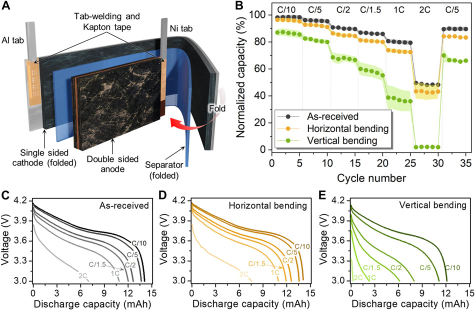
FIGURE 2. (A) Schematic of 15 mAh pouch cell configuration illustrating the cell component details and (B) electrochemical performance comparison at various C-rates before and after bending along the horizontal and vertical bending axes. Voltage profiles of 15 mAh pouch cell tested at various C-rates: (C) As-received and after (D) horizontal and (E) vertical bending.
To understand the role of bending orientation on the cell’s failure modes, the microstructural features of the electrodes after cell disassembly were investigated. Figure 3A shows photographs of the cathode, separator, and anode after they were removed from the horizontally bent cell and unfolded (inset shows the folded assembly). The electrode surfaces did not display noticeable creases as a result of repeated bending (Figure 3A), while several prominent creases were observed near the sealed seam of the packaging material (Supplementary Figure S4A). We believe that the stresses incurred near the horizontal bending axis caused the creasing and (in some cells) seal failure, resulting in electrolyte leakage (these cells were not further electrochemically cycled). Also, while the cathode film was observed to be torn in half at the crease where it was folded around the anode, the region where the tab was welded to the current collector remained well attached (enlarged image in Supplementary Figure S4B). Figures 3B, D show SEM images of the cathode and anode, respectively, while Figure 3C shows OM images of the separator. A closer look at the surface of the cathode along the bending axis revealed numerous micro-cracks (Figure 3B, OM images in Supplementary Figure S4C). It is important to note that crack propagation was observed not only around the cathode active materials, but also going through the active material particles. The identity of the fractured particle in Figure 3B was confirmed to be the cathode active material using EDS composition analysis (Supplementary Figure S4D). This suggests that the mechanical stresses experienced by the electrode during bending are sufficient to cause fracture to the cathode particle. Interestingly, the size of these cracks around the cathode particles was relatively small, ∼2 μm, compared to the particle size of the cathode particle. Also, very little damage was observed on the cathode-facing side of the separator, with only a few scratches observed perpendicular to the horizontal bending axis (Figure 3C). In contrast, the anode-facing side of the separator had noticeable damage, including rough scratches, perturbation of the polymer texture and alignment, and color variations. We suspect that due to the coarser shape of the anode materials (Figure 3D), they can damage the separator surface during bending, which can lead to formation of micro-short circuits during bending and/or electrochemical cycling. Indeed, noticeable deposits were observed near the tab-welding region and other areas of the anode after cell disassembly (Supplementary Figure S4E). Some of these appeared to be Li metal deposits, which implies that the physical detachment of anode active materials from the current collector during bending may have led to micro-short circuits and may also be responsible for the high overpotential seen in the discharge. In other cases, these features could be from excessive electrolyte decomposition, for instance on freshly exposed surfaces due to rupture of the solid electrolyte interface (SEI) passivation layer due to particle detachment. Same as for the cathode, micro-cracks were observed on the anode, particularly along the horizontal bending axis (Figure 3D, Supplementary Figure S4F).
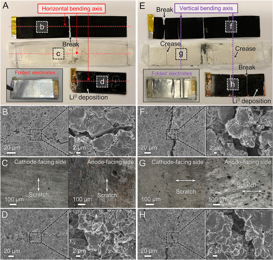
FIGURE 3. Microstructure observation of disassembled 15 mAh pouch cells after horizontal bending (A–D) or vertical bending (E–H) and electrochemical cycling. (A,E) Photographs of components after unfolding, with folded assembly in the inset. (B,F) SEM images of cathode. (C,G) OM images of separator facing each electrode. (D,H) SEM images of anode.
The cells subjected to bending in the vertical orientation showed noticeably different failure modes compared to horizontal bending. Both electrodes and the separator exhibited significant creases, tears, and material loss via particle detachment (Figure 3E, Supplementary Figure S5). In particular, the cathode had larger cracks (>6 µm wide) near the vertical bending axis (Figure 3F) compared to horizontal bending. Despite the strong creasing observed on the surface of the separator (Figure 3E), the OM images of the cathode-facing side of the separator did not show significant damage (Figure 3G). On the anode-facing side of the separator, a significant number of dark stains and deep scratches were seen (Figure 3G), which were caused by the anode materials rubbing off onto the surface. We also observed more deposition of Li metal and electrolyte precipitates (Supplementary Figure S5D), substantially larger cracks (Figure 3H), and delamination of the composite (Supplementary Figure S5E) on the anode after repeated bending in the vertical orientation compared to the horizontal. Interestingly, both bending orientations caused more notable damage to the anode compared to the cathode. Also, in both cases, repeated flexing appears to cause disconnection of electronic pathways (via crack formation) as well as reduction of composite adhesion (causing particle detachment), leading to higher internal resistance and decreased capacity delivery at high C-rates (i.e., reduced power performance).
The 25 mAh pouch cell achieves a higher nominal cell capacity and electrode size by using longer but narrower electrodes than in the 15 mAh cell (Table 1). This cell consists of a double-sided cathode, a single-sided anode, and a single folded separator placed between them (Figure 4A). One notable distinction of this particular pouch cell from the others is that the electrodes underwent a notching process (Lee et al., 2016). Therefore, the welded area was only on the notched portion of the electrode (Figure 4A inset). As shown in Table 1, the total thickness for all cell components in the 25 mAh cell is less than the total for the 15 mAh pouch cell. However, all of the 25 mAh cells evaluated, even the as-received cells, exhibited poor rate capabilities, with the 2C capacity only 33% of the C/10 capacity (Figure 4B). Consequently, both types of bending caused significant capacity loss at high C-rates. After horizontal flexing, the capacity was decreased to 90% of the pre-flex capacity even at a low C-rate of C/10, and it further decreased to 13% at a 2C rate. The discharge curves of cells subjected to horizontal bending also displayed higher overpotential than the as-received and vertically bent cells (Figures 4C–E). However, even in the vertically bending condition, more capacity loss was observed compared to the as-received cells (28% of capacity retention at a 2C rate and 80% in the C/5 recovery cycles).
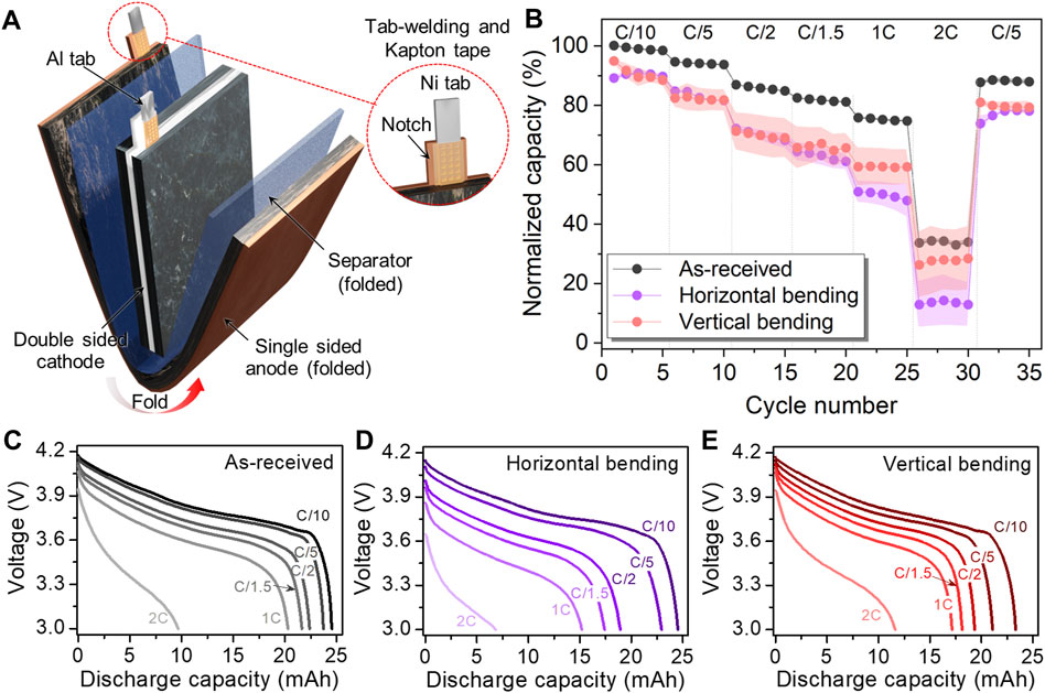
FIGURE 4. (A) Schematic of 25 mAh pouch cell configuration illustrating the cell component details and (B) electrochemical performance comparison at various C-rates before and after bending along the horizontal and vertical bending axes. Voltage profiles of 25 mAh pouch cell tested at various C-rates: (C) As-received and after (D) horizontal and (E) vertical bending.
We identified the reasons for the poor cycling performance in the 25 mAh cells after bending by conducting postmortem microstructure observation (Figure 5). After horizontal bending, noticeable creases appeared on the packaging (Supplementary Figure S6A) as well as both electrodes near the bending axis (Figure 5A) with coloration changes, likely due to the insufficient flexibility of the laminate packaging material. Supplementary Figure S6B includes enlarged images of the electrodes near the creased region. The creasing causes the cell components to no longer be planar, which can decrease the adhesion of the electrode film to the current collector and cause delamination of the composite coating; this was particularly noticeable on the anode (Supplementary Figure S6D). Similar to what was seen in the 15 mAh cell, SEM images showed the presence of crack formation near the bending axis of the electrodes (Figure 5B) but with larger crack widths. Detached particles and scratches perpendicular to the bending axis were also seen on the cathode-facing side of the separator, although no critical holes or damage that could potentially cause a short circuit were found (Figure 5C). The anode-facing side of the separator, especially in the crease area, showed noticeable scratches and discoloration (Figure 5G), similar to the observations in the 15 mAh cells. We believe the rough particle shape of the anode active particles, which are also relatively large, led to the formation of cracks on the surface of the electrode film (Figure 5D) and caused damage to the separator. This is consistent with OM images on the anode, where Li salt precipitates and/or Li metal deposits over a large area were found (Supplementary Figure S6E). EDS mapping of the anode also showed signs of Co, indicating detachment of cathode particles and the failure of the separator (Supplementary Figure S6F).
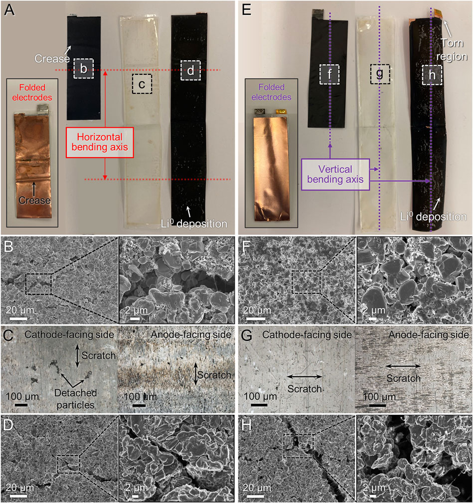
FIGURE 5. Microstructure observation of disassembled 25 mAh pouch cell after horizontal bending (A–D) or vertical bending (E–H) and electrochemical cycling. (A,E) Photographs of components after unfolding, with folded assembly in the inset. (B,F) SEM images of cathode. (C,G) OM images of separator facing each electrode. (D,H) SEM images of anode.
The vertically bent 25 mAh cells showed some different characteristics compared to those that were bent horizontally. The disassembled and unfolded electrodes and separator are presented in Figure 5E with the image of the folded stack in the inset. Similar to the case of horizontal bending, vertical bending caused noticeable creasing on the packaging materials and electrodes; however, the creasing was concentrated near the part where the electrodes were folded (Supplementary Figure S7A) and even led to tears at the fold (e.g., on the anode in Supplementary Figure S7D). The worst case was a tear observed in the tab-welding region (notch) of the anode near the bending axis (Supplementary Figure S7E), which can lead to breakage of the terminal connection. Although SEM imaging of the cathode (Figure 5F) showed little crack propagation near the vertical bending axis, multiple pores were visible throughout the surface of the cathode, which may cause a decrease in film cohesion. Upon examination of the cathode-facing side of the separator, it was noted that there were numerous stains from particle detachment along with vertical scratches that were aligned with the bending axis (Figure 5G). The separator texture was also changed, likely as a result of the tensile stress induced during flexing; in other words, the vertical bending axis may have affected the microstructure of the separator, e.g., by increasing separation between the polymer fibers. This was not as obvious during horizontal bending, likely due to the anisotropy of the separator, which has been widely reported (Love, 2011; Kalnaus et al., 2017). Similar to the cathode-facing side, the anode-facing side of the separator also exhibited noticeable stains from anode composite particles and scratches with texture changes suggesting fiber separation. This observation indicates that the microstructure of the separator and fiber orientation with respect to the bending axis may need to be considered when designing FLIBs. Finally, SEM observation of the anode surface revealed cracks measuring over 10 µm in width (Figure 5H), which revealed the underlying Cu current collector (Supplementary Figure S7F). EDS mapping also detected cathode material traces on the anode surface, possibly transferred through the damaged separator (Supplementary Figure S7F).
As in the 25 mAh pouch cell, the 50 mAh pouch cell consisted of a single-sided anode that was folded around a double-sided cathode. A distinguishing feature of this pouch cell from the others is the use of an additional separator to wrap around both electrodes and the uncoated, folded part of anode current collector, as depicted in Figure 6A, which is similar to the construction used in the flat winding cell stacking method for LIBs (Reinhart et al., 2013). Similar to the electrodes in the 15 mAh cell, the electrodes in the 50 mAh cell use tab-welding entirely along the edge of the current collector rather in a notched region as in the 25 mAh cell. Interestingly, the loss in capacity for the bent 50 mAh cells was not as high compared to the others (Figure 6B) and the voltage profiles showed less overpotential at the different C-rates (Figures 6C–E).
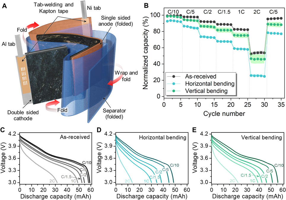
FIGURE 6. (A) Schematic of 50 mAh pouch cell configuration illustrating the cell component details and (B) electrochemical performance comparison at various C-rates before and after bending along the horizontal and vertical bending axes. Voltage profiles of 50 mAh pouch cell tested at various C-rates: (C) As-received and after (D) horizontal and (E) vertical bending.
As described earlier, the bending conditions used in the study resulted in only the 26 mm around the bending axis to be subjected to bending. Therefore, the 50 mAh cell was sufficiently large enough in size that the entire cell did not experience complete flexing when subjected to the horizontal bending condition. The effect of bending was concentrated near the bending axis, as demonstrated in Figure 7 and Supplementary Figure S8. Failure of the laminate seals at the creases (Supplementary Figure S8A) caused electrolyte leakage during the bending process. The disassembled electrodes showed severe creases, breaks, and cracks along the bending axis (Figure 7A), including tears in the welded portion of the current collector (Supplementary Figure S8B) and multiple breakages where the bending axis meets the fold in the anode (Supplementary Figure S8D). Near the bending axis area of the cathode, large cracks >6 µm wide were seen as indicated in Figure 7B. The wide crack width is caused by the large particle size of the cathode material secondary particles. As the secondary particles experience stress during bending, the formation of cracks depends on the size of the detached primary particles (de Vasconcelos et al., 2019). EDS mapping images confirmed the presence of cracks between the secondary particles (Supplementary Figure S8F), and detached cathode materials were found adhered to the separator (dark regions in Figure 7C). Large cracks measuring approximately 20 µm in width were also observed on the anode surface (Figure 7D).
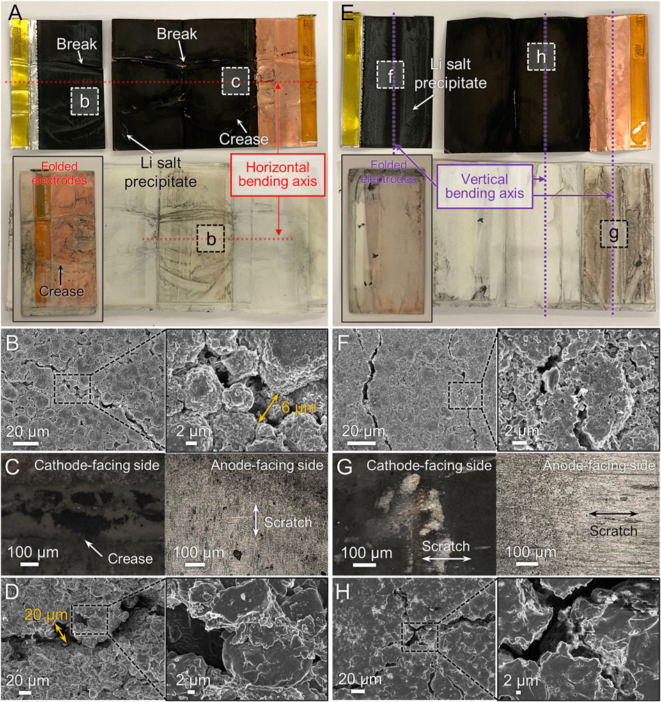
FIGURE 7. Microstructure observation of disassembled 50 mAh pouch cell after horizontal bending (A–D) or vertical bending (E–H) and electrochemical cycling. (A,E) Photograph of components after unfolding, with folded assembly in the inset. (B,F) SEM images of cathode. (C,G) OM images of separator facing each electrode. (D,H) SEM images of anode.
The vertically bent 50 mAh cells showed slightly different postmortem characteristics. No significant tears were seen in the packaging (Supplementary Figure S9A) or on the cathode (Supplementary Figure S9B), and the welded regions were still well connected to the current collector. However, tears along the folded region of the anode current collector were observed (Figure 7E and Supplementary Figure S9D). Extracted active materials or/and residual Li-containing compounds from the electrolyte were also observed on top of both electrodes (Supplementary Figure S9B). Crack propagation on the cathode surface along the bending axis was seen (Figure 7F) with the crack width similar to or smaller than those in the horizontally bent electrode (Figure 7B). It was also consistently observed that the cracks formed in the anode were narrower after vertical bending than in horizontal bending (Figure 7H) although EDS mapping could detect exposed Cu current collector (Supplementary Figure S9F), indicating fairly deep cracks. However, larger portions of the separator were covered with scratches and delaminated materials from electrodes on both sides (Figure 7G) compared to horizontal bending. While the vertically bent cells experienced more curvature due to the length dimension being compatible with the active bending length of 26 mm, the horizontally bent electrodes displayed worse electrochemical performance, despite having less area subjected to bending. It is interesting to note that the 50 mAh pouch cell exhibits better electrochemical performance considering both bending directions compared to the other cells despite all of the observed damage. We believe this is because of the additional separator that was wrapped around the cell components to hold them together and prevent their separation. This setup allows for improved connectivity even if some of the electrode composites become detached from the current collectors. However, it is not completely foolproof as gas buildup observed in the cells after bending, and all of the aforementioned microstructure degradation, suggest that repeated flexing still has significant impacts on the cell integrity.
The mechanical failure modes seen in the ultrathin pouch cells and their impacts on electrochemical performance are schematically summarized in Figure 8. First, due to the repeated back and forth bending used in our study, the same compressive and tensile stresses are applied to both sides of the electrodes. When a pair of single-sided electrodes are flexed with a separator between them, the front and back of the electrodes, as well as each interface, can experience both compressive and tensile stress. However, when utilizing cell components that are not evenly balanced (e.g., different electrode sizes), this may cause different stress distributions between the bulk structure and outer surface of the pouch cell. As a result, the interfaces likely experience different stresses during flexing due to mechanical friction between each portion (Figure 8A). Due to the smaller area of the anode compared to the cathode in the 15 mAh pouch cell, damage to the anode results in more significant loss of capacity.
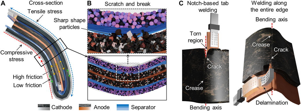
FIGURE 8. Schematics illustrating the correlation of mechanical failure modes and electrochemical performance of the electrode. (A) Various types of stress and (B) differences in particle size and shape in the electrode composite film can lead to scratches on the separator as well as particle detachment (shown in cross-section). (C) Creases, crack propagation, and tears in the electrode and composite delamination can take place in thick parts of the cells (such as near the notch used for tab welding) and/or near the bending axes.
Second, the choice of active material size and microstructure can play an important role in causing failure during bending. Mechanical friction may increase when using large or sharp-edged active material particles in the electrode films (Figure 8B) and cause damage to the separator, as we observed for the anodes in the 15 and 25 mAh pouch cells. The fracture of the cathode single crystals in the 15 mAh cells and the cathode secondary particles in the 50 mAh cells is also notable. Several research groups have investigated the fracture of various cathode active materials using nanoindentation with and without electrochemical cycling (Swallow et al., 2014; Xu et al., 2017; de Vasconcelos et al., 2019) and found the particle morphology of the active materials to be the most important factor in the mechanical fracture process. For example, when particles agglomerate into secondary particles, they are affected by the electrolyte absorption into pores between primary particles, which can increase the binding force between them and increase the fracture strength. In the case of a single crystal structure, large and plate-shaped particles can become easily fractured (Hitt et al., 2022). Cracks in the electrode materials can induce vacancies or pores in the materials and an undesired increase in the void volume. These vacancies may act as sites for side reactions during electrochemical cycling, such as electrolyte decomposition, Li metal deposition, and Li salt precipitation from the electrolyte onto the electrode surfaces, all processes which can lead to loss in capacity (Kim et al., 2019).
Third, the range of bending that the electrode can withstand is also affected by the location of the tab weld. The tab components are typically thicker than the other parts of the entire pouch cell, and the thickness plays a crucial role in determining their overall flexibility (Figure 8C). The orientation of the welded region with respect to the bending axis can also either promote or prevent electrode failure due to tears. The notch-based tab welding used in the 25 mAh cell limited exposure of the tab region to both bending axes, but the smaller welded area also makes it more vulnerable to complete electrical disconnection due to tearing. On the other hand, use of tab welding along the entire edge of the current collector (as in the 15 and 50 mAh cells), exposes a larger area to damage unless the bending axis is parallel to the welded edge.
Fourth, the creases created by folding the electrodes are vulnerable to breakage and should be avoided in order to mitigate electrical disconnection of large portions of the electrodes. Instead, cell assembly processes that do not use folding such as single sheet stacking or Z-folding with single electrodes (Reinhart et al., 2013) would circumvent this problem. The results from the 50 mAh cells show that even if critical mechanical failures occur, maintaining good physical connections through separator wrapping can partially help mitigate the deleterious effects. However, adding an extra separator or protective layer to the flexible battery increases its thickness and reduces flexibility, which can lead to mechanical friction and excessive stress between the layers.
Last but not least, orienting the bending axis so that a rectangular-shaped pouch cell is flexed along its longest dimension appears to be a crucial factor for reducing mechanical failure. This can explain why horizontal bending is better than vertical bending for the short but wide 15 mAh cell, while vertical bending is better than horizontal bending for the tall and narrower 25 and 50 mAh cells. The anisotropy of the texture and mechanical properties of the separator may also need to be considered. In instances where electrode active materials have sharp edges and the separator texture is aligned in the same direction with the bending axis, there is a possibility of critical failure during electrochemical cycling after flexing. This can lead to an increase in localized stress, causing severe damage such as cracks and breakage of cell components. Such critical damage may cause undesired side reactions and unfavorable outcomes during the electrochemical reactions.
The summary of observed failure modes given above suggests that the impact of bending is highly dependent on the physical design factors of the cell. However, we point out that this study was carried out on commercially available cells where the choice of anode, cathode, separator, and cell design could not be controlled systematically to identify the most critical factors. We anticipate that the design of more robust FLIBs will need consideration of the physical design factors as well as improvements in the mechanical properties of the cell components. For instance, electrode composites should be developed (e.g., through choice of binder and/or conducting additive) (Gaikwad and Arias, 2017; Kim et al., 2024) with improved cohesion to resist crack formation and propagation, and better adhesion to prevent delamination and particle detachment during repeated bending. Separators with isotropic mechanical properties and better resistance to puncture by detached particles are also needed. The poor adhesion of the electrode composites and failure of the separator to prevent internal short circuits likely contributed to the severe swelling and gas generation we observed in the cells while they were undergoing the bending cycles (notably, in their fully discharged state and without simultaneous electrochemical cycling–we expect the effect to be exacerbated for charged cells or cells under active operation). Finally, thinner and more flexible laminates with stronger sealing properties to prevent creasing and electrolyte leakage during bending are critically needed, particularly if thicker or higher capacity FLIBs are desired.
In summary, the various kinds of mechanical failure modes in three types of ultrathin Li-ion pouch cells subjected to repeated flexing along two distinct bending axes were identified, as well as the impacts of the observed failures on the electrochemical cycling performance. The cell design and orientation of bending is found to play a large role in the observed microstructure damage to the components and capacity loss. We find the least significant capacity loss when the bending axis is parallel to the longest dimension of the cell. Furthermore, we highlight the importance of avoiding particles with large and sharp shapes in the electrode composites as they can cause significant mechanical damage to the other pouch cell components. Such damage can lead to unfavorable outcomes during electrochemical reactions or short-circuit of the battery. The configuration of components is also crucial for enhancing the electrochemical performance of flexible batteries.
The raw data supporting the conclusions of this article will be made available by the authors, without undue reservation.
KK: Conceptualization, Data curation, Formal Analysis, Investigation, Methodology, Visualization, Writing–original draft. CC: Conceptualization, Data curation, Funding acquisition, Project administration, Supervision, Writing–original draft, Writing–review and editing.
The author(s) declare that financial support was received for the research, authorship, and/or publication of this article. The work was supported by the U.S. Government. The views in this article do not necessarily represent the view of the U.S. Government. The U.S. Government and the publisher, by accepting this article for publication, acknowledge that the U.S. Government retains a nonexclusive, paid-up, irrevocable, worldwide license to publish or reproduce the published form of this work, or allow others to do so, for U.S. Government purposes.
The authors acknowledge the use of facilities within the Eyring Materials Center (supported in part by NNCI-ECCS-1542160) and thank M. Chiu, Z. Song, and H. Jiang for helpful discussions.
The authors declare that the research was conducted in the absence of any commercial or financial relationships that could be construed as a potential conflict of interest.
All claims expressed in this article are solely those of the authors and do not necessarily represent those of their affiliated organizations, or those of the publisher, the editors and the reviewers. Any product that may be evaluated in this article, or claim that may be made by its manufacturer, is not guaranteed or endorsed by the publisher.
The Supplementary Material for this article can be found online at: https://www.frontiersin.org/articles/10.3389/fbael.2024.1371167/full#supplementary-material
Bates, A. M., Preger, Y., Torres-Castro, L., Harrison, K. L., Harris, S. J., and Hewson, J. (2022). Are solid-state batteries safer than lithium-ion batteries? Joule 6, 742–755. doi:10.1016/j.joule.2022.02.007
Blake, A. J., Kohlmeyer, R. R., Drummy, L. F., Gutiérrez-Kolar, J. S., Carpena-Núñez, J., Maruyama, B., et al. (2016). Creasable batteries: understanding failure modes through dynamic electrochemical mechanical testing. ACS Appl. Mat. Interfaces 8, 5196–5204. doi:10.1021/acsami.5b11175
Chang, J., Huang, Q., and Zheng, Z. (2020). A Figure of merit for flexible batteries. Joule 4, 1346–1349. doi:10.1016/j.joule.2020.05.015
Chen, A., Guo, X., Yang, S., Liang, G., Li, Q., Chen, Z., et al. (2021a). Human joint-inspired structural design for a bendable/foldable/stretchable/twistable battery: achieving multiple deformabilities. Energy Environ. Sci. 14, 3599–3608. doi:10.1039/d1ee00480h
Chen, Y., Kang, Y., Zhao, Y., Wang, L., Liu, J., Li, Y., et al. (2021b). A review of lithium-ion battery safety concerns: the issues, strategies, and testing standards. J. Energy Chem. 59, 83–99. doi:10.1016/j.jechem.2020.10.017
Cheng, Q., Song, Z., Ma, T., Smith, B. B., Tang, R., Yu, H., et al. (2013). Folding paper-based lithium-ion batteries for higher areal energy densities. Nano Lett. 13, 4969–4974. doi:10.1021/nl4030374
de Vasconcelos, L. S., Sharma, N., Xu, R., and Zhao, K. (2019). In-situ nanoindentation measurement of local mechanical behavior of a Li-ion battery cathode in liquid electrolyte. Exp. Mech. 59, 337–347. doi:10.1007/s11340-018-00451-6
Divakaran, A. M., Minakshi, M., Bahri, P. A., Paul, S., Kumari, P., Divakaran, A. M., et al. (2021). Rational design on materials for developing next generation lithium-ion secondary battery. Prog. Solid State Chem. 62, 100298. doi:10.1016/j.progsolidstchem.2020.100298
Ebner, M., Marone, F., Stampanoni, M., and Wood, V. (2013). Visualization and quantification of electrochemical and mechanical degradation in Li ion batteries. Science 342, 716–720. doi:10.1126/science.1241882
Gaikwad, A. M., and Arias, A. C. (2017). Understanding the effects of electrode formulation on the mechanical strength of composite electrodes for flexible batteries. ACS Appl. Mat. Interfaces 9, 6390–6400. doi:10.1021/acsami.6b14719
Gaikwad, A. M., Khau, B. V., Davies, G., Hertzberg, B., Steingart, D. A., and Arias, A. C. (2015). A high areal capacity flexible lithium-ion battery with a strain-compliant design. Adv. Energy Mater. 5, 141389. doi:10.1002/aenm.201401389
Galos, J., Best, A. S., and Mouritz, A. P. (2020). Multifunctional sandwich composites containing embedded lithium-ion polymer batteries under bending loads. Mater. Des. 185, 108228. doi:10.1016/j.matdes.2019.108228
Ge, X., Cao, S., Lv, Z., Zhu, Z., Tang, Y., Xia, H., et al. (2022). Mechano-graded electrodes mitigate the mismatch between mechanical reliability and energy density for foldable lithium-ion batteries. Adv. Mater. 34, e2206797. doi:10.1002/adma.202206797
Harris, S. J., Harris, D. J., and Li, C. (2017). Failure statistics for commercial lithium ion batteries: a study of 24 pouch cells. J. Power Sources 342, 589–597. doi:10.1016/j.jpowsour.2016.12.083
Hitt, A., Wang, F., Li, Z., Ge, M., Zhang, Y., Savsatli, Y., et al. (2022). Nanotomographic observation and statistical analysis of overcharging induced cracks in LiCoO2 single crystalline particles. Energy Storage Mater. 52, 320–328. doi:10.1016/j.ensm.2022.08.011
Jansen, A. N., Amine, K., Newman, A. E., Vissers, D. R., and Henriksen, G. L. (2002). Low-cost, flexible battery packaging materials. JOM 54, 29–32. doi:10.1007/bf02822616
Jeong, I., Han, D. Y., Hwang, J., Song, W. J., and Park, S. (2022). Foldable batteries: from materials to devices. Nanoscale Adv. 4, 1494–1516. doi:10.1039/d1na00892g
Ji, W., Qu, H., Zhang, X., Zheng, D., and Qu, D. (2021). Electrode architecture design to promote charge-transport kinetics in high-loading and high-energy lithium-based batteries. Small Methods 5, e2100518. doi:10.1002/smtd.202100518
Jia, S. K., Yang, B. Z., Zhao, C. F., Zhang, Z. Y., Yin, Y. H., Liu, X. B., et al. (2021). Tab engineering-mediated resistance of flexible lithium-ion batteries for high output current. J. Energy Chem. 58, 264–270. doi:10.1016/j.jechem.2020.10.018
Kalnaus, S., Wang, Y., and Turner, J. A. (2017). Mechanical behavior and failure mechanisms of Li-ion battery separators. J. Power Sources 348, 255–263. doi:10.1016/j.jpowsour.2017.03.003
Kim, C. S., Jeong, K. M., Kim, K., and Yi, C. W. (2015). Effects of capacity ratios between anode and cathode on electrochemical properties for lithium polymer batteries. Electrochimica Acta 155, 431–436. doi:10.1016/j.electacta.2014.12.005
Kim, J. Y., Yoo, K. T., Kim, D. O., Lee, M. H., Yang, W. J., and Byeon, J. W. (2019). Evaluation of health and safety of mechanically fatigued rechargeable lithium polymer batteries for flexible electronics applications. Microelectron. Reliab. 100–101, 113441. doi:10.1016/j.microrel.2019.113441
Kim, K., Loh, R., Martinez, R., Chan, C. K., and Hwa, Y. (2024). Failure modes of flexible LiCoO2 cathodes incorporating polyvinylidene fluoride binders with different molecular weights. ACS Appl. Mat. Interfaces 16, 5926–5936. doi:10.1021/acsami.3c17310
Kim, K. H., Song, Y. J., and Ahn, H. J. (2023). Protein-assisted bendable Cu-free anode: hydroxy-functionalized mesoporous carbon matrix for flexible Li-ion batteries. Appl. Surf. Sci. 608, 155084. doi:10.1016/j.apsusc.2022.155084
Kuang, Y., Chen, C., Kirsch, D., and Hu, L. (2019). Thick electrode batteries: principles, opportunities, and challenges. Adv. Energy Mater. 9, 1–19. doi:10.1002/aenm.201901457
Lall, P., Soni, V., and Miller, S. (2020). “Effect of dynamic folding with varying fold orientations and C-rates on flexible power source capacity degradation,” in 2020 19th IEEE Intersociety Conference on Thermal and Thermomechanical Phenomena in Electronic Systems (ITherm), Orlando, FL, USA, 21-23 July 2020 (IEEE), 854–860. doi:10.1109/ITherm45881.2020.9190446
Lee, J. H., Yang, G., Kim, C. H., Mahajan, R. L., Lee, S. Y., and Park, S. J. (2022). Flexible solid-state hybrid supercapacitors for the internet of everything (IoE). Energy Environ. Sci. 15, 2233–2258. doi:10.1039/d1ee03567c
Lee, J. U., Lee, H. E., Heo, S. K., Lee, H. K., and Lee, I. B. (2016). Midterm scheduling for the production of a stack and folding-type battery using a hierarchical method. Ind. Eng. Chem. Res. 55, 10132–10146. doi:10.1021/acs.iecr.6b01808
Lee, Y. H., Kim, J. S., Noh, J., Lee, I., Kim, H. J., Choi, S., et al. (2013). Wearable textile battery rechargeable by solar energy. Nano Lett. 13, 5753–5761. doi:10.1021/nl403860k
Li, H., Tang, Z., Liu, Z., and Zhi, C. (2019). Evaluating flexibility and wearability of flexible energy storage devices. Joule 3, 613–619. doi:10.1016/j.joule.2019.01.013
Li, X., Ling, S., Zeng, L., He, H., Liu, X., and Zhang, C. (2022). Directional freezing assisted 3D printing to solve a flexible battery dilemma: ultrahigh energy/power density and uncompromised mechanical compliance. Adv. Energy Mater. 12, 2200233. doi:10.1002/AENM.202200233
Liu, X., Zhao, J., Wang, J., Le, Z., Nie, P., Wang, H., et al. (2022). Electrolyte-philic and thermal-resistant polyimide separator enhances the performance of flexible silicon/carbon nanofibers for lithium-ion batteries. J. Energy Storage 54, 105324. doi:10.1016/j.est.2022.105324
Love, C. T. (2011). Thermomechanical analysis and durability of commercial micro-porous polymer Li-ion battery separators. J. Power Sources 196, 2905–2912. doi:10.1016/j.jpowsour.2010.10.083
Mackanic, D. G., Kao, M., and Bao, Z. (2020). Enabling deformable and stretchable batteries. Adv. Energy Mater. 10, 1–10. doi:10.1002/aenm.202001424
Mokhtari, F., Cheng, Z., Raad, R., Xi, J., and Foroughi, J. (2020). Piezofibers to smart textiles: a review on recent advances and future outlook for wearable technology. J. Mat. Chem. A 8, 9496–9522. doi:10.1039/d0ta00227e
Park, Y., Park, G., Park, J. g., and Lee, Jw (2017). Robust free-standing electrodes for flexible lithium-ion batteries prepared by a conventional electrode fabrication process. Electrochimica Acta 247, 371–380. doi:10.1016/j.electacta.2017.07.032
Qian, G., Zhu, B., Liao, X., Zhai, H., Srinivasan, A., Fritz, N. J., et al. (2018). Bioinspired, spine-like, flexible, rechargeable lithium-ion batteries with high energy density. Adv. Mater. 30, 1704947. doi:10.1002/adma.201704947
Reinhart, G., Zeilinger, T., Kurfer, J., Westermeier, M., Thiemann, C., Glonegger, M., et al. (2013). “Research and demonstration center for the production of large-area lithium-ion cells,” in Future trends in production engineering. Editors G. Schuh, R. Neugebauer, and E. Uhlmann (Berlin, Heidelberg: Springer), 3–12. doi:10.1007/978-3-642-24491-9_1
Song, Z., Ma, T., Tang, R., Cheng, Q., Wang, X., Krishnaraju, D., et al. (2014). Origami lithium-ion batteries. Nat. Commun. 5, 3140. doi:10.1038/ncomms4140
Swallow, J. G., Woodford, W. H., McGrogan, F. P., Ferralis, N., Chiang, Y.-M., and Van Vliet, K. J. (2014). Effect of electrochemical charging on elastoplastic properties and fracture toughness of LiXCoO2. J. Electrochem. Soc. 161, F3084–F3090. doi:10.1149/2.0141411jes
Wang, F., Zhang, L., Zhang, Q., Yang, J., Duan, G., Xu, W., et al. (2021). Electrode thickness design toward bulk energy storage devices with high areal/volumetric energy density. Appl. Energy 289, 116734. doi:10.1016/j.apenergy.2021.116734
Wehner, L. A., Mittal, N., Liu, T., and Niederberger, M. (2021). Multifunctional batteries: flexible, transient, and transparent. ACS Cent. Sci. 7, 231–244. doi:10.1021/acscentsci.0c01318
Woo, S. G., Yoo, S., Lim, S. H., Yu, J. S., Kim, K., Lee, J., et al. (2020). Galvanically replaced, single-bodied lithium-ion battery fabric electrodes. Adv. Funct. Mater. 30, 1908633. doi:10.1002/adfm.201908633
Wu, J., Ju, Z., Zhang, X., Takeuchi, K. J., Marschilok, A. C., Takeuchi, E. S., et al. (2021). Building efficient ion pathway in highly densified thick electrodes with high gravimetric and volumetric energy densities. Nano Lett. 21, 9339–9346. doi:10.1021/acs.nanolett.1c03724
Xu, R., de Vasconcelos, L. S., Shi, J., Li, J., and Zhao, K. (2018). Disintegration of meatball electrodes for LiNixMnyCozO2 cathode materials. Exp. Mech. 58, 549–559. doi:10.1007/s11340-017-0292-0
Xu, R., Sun, H., de Vasconcelos, L. S., and Zhao, K. (2017). Mechanical and structural degradation of LiNixMnyCozO2 cathode in Li-ion batteries: an Experimental Study. J. Electrochem. Soc. 164, A3333–A3341. doi:10.1149/2.1751713jes
Yu, B., Fan, Y., Mateti, S., Kim, D., Zhao, C., Lu, S., et al. (2021). An ultra-long-life flexible lithium-sulfur battery with lithium cloth anode and polysulfone-functionalized separator. ACS Nano 15, 1358–1369. doi:10.1021/acsnano.0c08627
Zhang, Y., Li, F., Yang, K., Liu, X., Chen, Y., Lao, Z., et al. (2021). Polymer molecular engineering enables rapid electron/Ion transport in ultra-thick electrode for high-energy-density flexible lithium-ion battery. Adv. Funct. Mater. 31, 2100434. doi:10.1002/adfm.202100434
Zheng, H., Li, J., Song, X., Liu, G., and Battaglia, V. S. (2012). A comprehensive understanding of electrode thickness effects on the electrochemical performances of Li-ion battery cathodes. Electrochimica Acta 71, 258–265. doi:10.1016/j.electacta.2012.03.161
Zhou, G., Li, L., Ma, C., Wang, S., Shi, Y., Koratkar, N., et al. (2015). A graphene foam electrode with high sulfur loading for flexible and high energy Li-S batteries. Nano Energy 11, 356–365. doi:10.1016/j.nanoen.2014.11.025
Keywords: flexible batteries, lithium-ion batteries, pouch cells, mechanical failure, design parameters
Citation: Kim K and Chan CK (2024) Design parameters affecting mechanical failure and electrochemical degradation of ultrathin Li-ion pouch cells under repeated flexing. Front. Batteries Electrochem. 3:1371167. doi: 10.3389/fbael.2024.1371167
Received: 16 January 2024; Accepted: 15 February 2024;
Published: 06 March 2024.
Edited by:
Guosheng Li, Pacific Northwest National Laboratory (DOE), United StatesReviewed by:
J. P. Rong, Hithium Energy Storage USA Inc., United StatesCopyright © 2024 Kim and Chan. This is an open-access article distributed under the terms of the Creative Commons Attribution License (CC BY). The use, distribution or reproduction in other forums is permitted, provided the original author(s) and the copyright owner(s) are credited and that the original publication in this journal is cited, in accordance with accepted academic practice. No use, distribution or reproduction is permitted which does not comply with these terms.
*Correspondence: Candace K. Chan, Y2FuZGFjZS5jaGFuQGFzdS5lZHU=
Disclaimer: All claims expressed in this article are solely those of the authors and do not necessarily represent those of their affiliated organizations, or those of the publisher, the editors and the reviewers. Any product that may be evaluated in this article or claim that may be made by its manufacturer is not guaranteed or endorsed by the publisher.
Research integrity at Frontiers
Learn more about the work of our research integrity team to safeguard the quality of each article we publish.