- Institute of Electrical and Micro Engineering, Laboratory of Wave Engineering, Ecole Polytechnique Fédérale de Lausanne (EPFL), Lausanne, Switzerland
We introduce a Lamb-wave medium with tunable propagation velocities, which are controlled by a two-dimensional heating pattern produced by a laser beam. We utilized it to demonstrate that waves in an appropriately designed medium can propagate in the form of concentric squares, in contrast to the circular patterns typically emitted by a point source in a homogeneous two-dimensional medium. In order to avoid the concentration of wave energy in the middle of the sides of the squares, we propose two alternatives: a square wave that either rotates or exponentially decelerates as it expands. Additionally, we present how circular waves can be transformed into spiral waves utilizing the same tunable medium. The described experimental platform offers a new tool to generate shaped pulses for ultrasonic applications, which has the potential to improve the efficiency of energy and information transport.
1 Introduction
There has been a persistent pursuit to control waves with the aim of increasing the efficiency of energy, momentum, and information that propagating waves can transfer. This is not limited solely to wave manipulation at the emitting and receiving points—the overall performance of wave-based devices can also be enhanced by interventions along the entire wave propagation path. The properties of the wave propagation medium can be designed in a way that better serves a wide variety of intended purposes. For example, it can facilitate the distribution of relevant information from the emitter to the receiver or concentrate distributed energy at a specific point where it can be harvested.
Wavefront shaping is frequently used in various optical applications, such as focusing light through scattering media like biological tissues, and enhancing the resolution and contrast of imaging (Booth, 2007; Tay et al., 2014; Fayyaz et al., 2019; Feng et al., 2019; Hampson et al., 2021). It is frequently used in astronomical imaging to correct for atmospheric turbulences (Beckers, 1993). Typically, in optics, a spatial light modulator or a digital micromirror device is used as the reconfigurable element to achieve wavefront shaping (Vellekoop and Mosk, 2007; Vellekoop and Mosk, 2008; Katz et al., 2011; Mosk et al., 2012; Liu et al., 2021; Yu et al., 2022).
Wavefront shaping is also applicable to microwaves for creating beams with specific directivity and pattern shapes. The reconfigurable element in this context is a spatial microwave modulator or binary programmable metasurface (Kaina et al., 2014; Dupré et al., 2015; Li et al., 2016; Chen et al., 2020; Frazier et al., 2020; Lin et al., 2021).
Taking inspiration from the fields of optics and microwaves, spatial sound modulators have been employed to shape sound fields in the audible frequency range. To achieve significant control over the sound field with minimal parameter variations, the active elements of these reconfigurable devices can consist of membrane or hollow cavity resonators. They have been demonstrated based on electromagnetic actuators (Ma et al., 2018), slider displacements (Chen et al., 2019; Wang et al., 2019; Prat-Camps et al., 2020; Zhang et al., 2021), or liquid level height control (Tian et al., 2020) for the purpose of sound focusing or redirecting. However, in the ultrasonic frequency range, wavefront shaping is typically limited to the use of expensive phased arrays or actuators. The reason for this is the increased attenuation levels in the higher ultrasound frequency range, leading to shorter propagation paths.
In this work, we achieve wavefront shaping for Lamb wave pulses by exploiting optothermal effects controlled by a laser, demonstrating pulses that propagate as squares and spirals instead of the standard circular phase fronts. Our experimental setup allows for on-demand control of the propagation velocity in two spatial dimensions within a non-periodic structure. This opens up possibilities for integral control of wave shapes throughout the entire medium and the study of wave propagation in various mathematical spaces. Furthermore, our method is not reliant on resonant behavior and is therefore not limited to a narrow frequency range, which was a limitation in previous implementations (Kaina et al., 2014; Dupré et al., 2015; Chen et al., 2019; Frazier et al., 2020; Prat-Camps et al., 2020; Tian et al., 2020).
2 Materials and methods
The specimen consisted of a 0.4-mm thick foil made from a shape memory polymer (SMP) (manufacturer: SMP Technologies Inc., Tokyo), which exhibits a glass transition temperature in the range from 25°C to 90°C (Firouzeh et al., 2017). As a consequence, its Young’s modulus decreases by a factor of 20 when the temperature is raised by just a few tens of degrees above room temperature. The advantage exploited in this work was the ease of reconfiguring wave propagation properties by altering the temperature field of the SMP foil in two dimensions. Achieving similar performance using an electric field to control propagation properties would be technically complicated, making it a challenging alternative (White et al., 2008; Iqbal and Samiullah, 2013; Apffel and Fort, 2022).
The SMP foil was mounted on a metal frame (Figure 1A) with an opening of 3 cm × 3 cm. The Lamb waves were excited at the position (x, y) = (0, 0) using a laser pulse with a wavelength of 532 nm, energy of 10 mJ, duration of 5 ns (full width at half-maximum), and a repetition rate of 20 Hz, employing a Surelite SL I-20 pump laser (Figure 1B). Lamb waves were excited 10 times for each pixel of the two-dimensional scans in Figures 2B, C, D to Figures 6B, C, D to achieve sufficient averaging. A laser vibrometer PSV-F-500-HV (manufacturer: Polytec) with two integrated galvanometric mirrors was utilized to direct the probe laser beam to the desired scanning position (Figure 1C). The synchronization of the setup components and high repeatability of the ultrasound excitation, propagation, and detection enabled us to render the scans from individual punctual measurements.
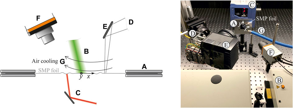
FIGURE 1. The reconfigurable medium consisted of a shape memory polymer (SMP) foil mounted in a metallic frame (A). Lamb waves were excited using a pulsed laser (B). For each scanning position, Lamb waves were separately excited and detected by a laser vibrometer with integrated scanning galvanometric mirrors (C). A heating laser (D) was projected onto the specimen surface by another external galvanometer scan head (E) to perform two-dimensional manipulation of mechanical properties. The temperature field of the specimen was captured by an infrared camera (F). The SMP foil was cooled by room-temperature airflow (G).
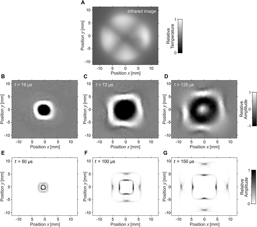
FIGURE 2. The inhomogeneity of the medium (SMP foil) required for square wave propagation was achieved through the temperature field, created by selective laser heating, as visible on the image of the infrared camera (A). Three time instances of the measured Lamb waves generated by a laser pulse propagating in a square shape are presented (B–D). The faster zero-order symmetrical mode is visible only in the numerical simulation (E–G). Focusing on the four areas with slower wave propagation in the middle of the sides of the squares is present (Supplementary Material).
A third laser (FL-1064-CW, manufacturer: Changchun New Industries Optoelectronics Technology) illuminated the specimen from the side opposite to the wave excitation and was a continuous laser with a wavelength of 1064 nm (Figure 1D). Its power varied for different measurements: 7 W for Figure 2, 12 W for Figure 3, 5.4 W for Figure 4, and 2.2 W for Figure 6. The positioning of the heating laser on the side opposite to the laser vibrometer was crucial to avoid disturbances caused by hot air, which could potentially alter the optical path of the laser vibrometer beam.
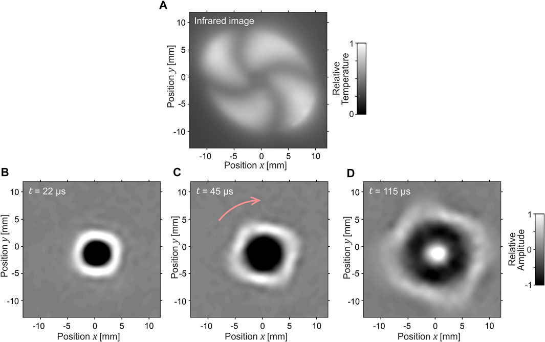
FIGURE 3. One way to reduce the focusing effect is to have the square rotate as it propagates. This rotation is achieved through the temperature field, which can be observed using an infrared camera (A). Three time instances of the square wave as it expands and rotates nearly 45° in the direction indicated by the pink arrow are displayed in (B–D) (Supplementary Material).
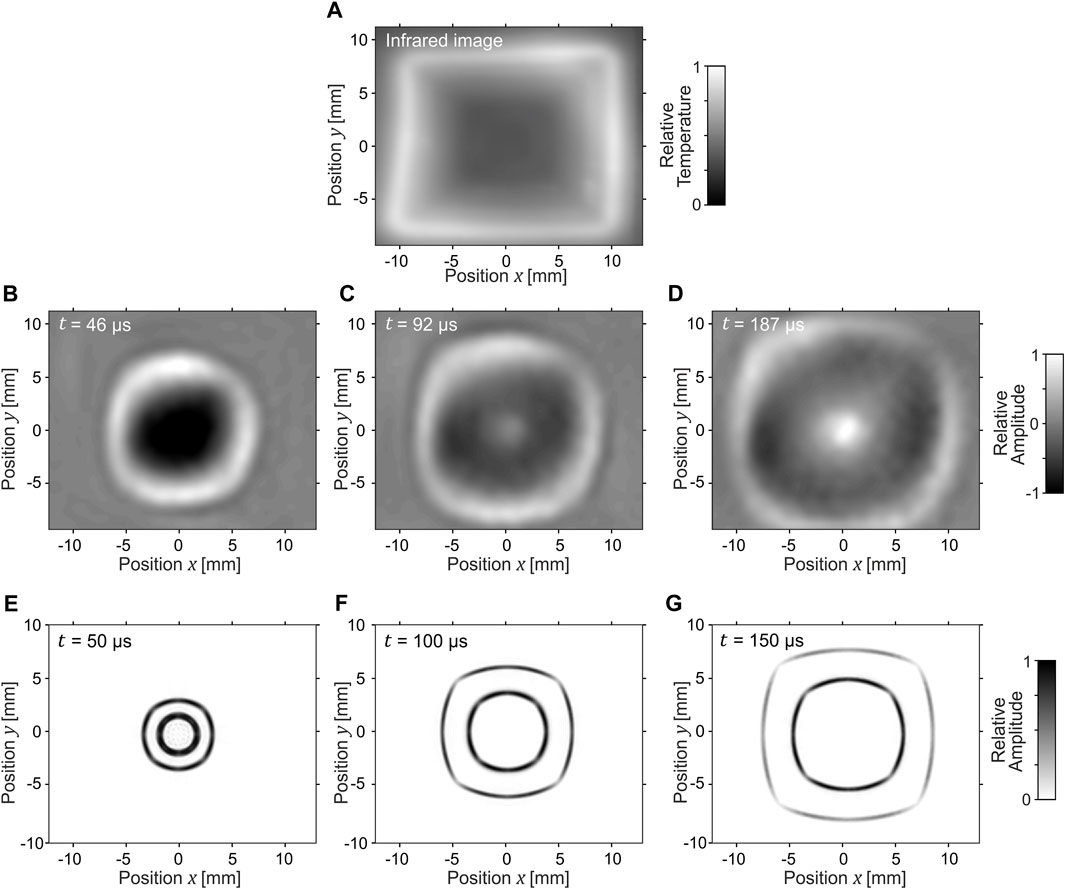
FIGURE 4. The second option to avoid the focusing effect, and the only one to achieve square wave propagation without rotation, is to have the wave slow down exponentially. As seen in the infrared camera image, isothermal areas (indicating the same wave propagation speed) take the forms of squares (A). The zero-order antisymmetric Lamb wave mode is visible in the measurement (B–D), while both symmetrical and antisymmetrical modes are observable in the numerical simulation (E–G) (Supplementary Material).
A XG210 2-axis galvanometer scan head (manufacturer: Mecco) was utilized to project the heating pattern onto the specimen surface (Figure 1E). The temperature field was controlled by the density of the projected lines of the third laser rather than the variation in power intensity. The temperature field was measured using an infrared camera Gobi 640 (manufacturer: Xenics) (Figure 1F). The exposure time was 25 µs. Temperature calibration of the camera for the specific material properties of the SMP foil was not necessary since the relative temperature distribution is of importance, rather than the absolute values. The maximum temperature increase was approximately 40°C. The shape of the projected pattern is described in the following section for each of the measurements individually. The scan repetition rate was approximately 2 Hz.
The heated area of the SMP foil was cooled by room-temperature airflow, which was directed to the specimen surface on the side of the wave excitation using a nozzle (Figure 1G). This approach allowed us to achieve increased spatial temperature gradients.
3 Results
To demonstrate the capability of the reconfigurable medium, we tuned the wave velocity in two-dimensional space to compel the wave fronts of the zero-order antisymmetric Lamb mode to propagate in the forms of squares (two approaches), rotating squares, and spirals. To the best of our knowledge, there is no prior art reporting waves shaped as squares. On the other hand, there are several physical phenomena, typically associated with rotating objects, that can excite spiral-shaped waves capable of propagating in a homogeneous medium (Bordyugov and Engel, 2007; Hermann and Gottwald, 2010; Li et al., 2017). A famous example is the gravitational waves emitted by orbiting binaries (Pretorius, 2005; Kyutoku et al., 2021). Spiral waves have also been observed on a water surface (Islam et al., 2023) and in a cardiac muscle (Davidenko et al., 1992).
Achieving wave propagation in the shape of squares required the wave velocity to be
where the angle
The temperature field, following Eq. 1, was created by projecting 5 concentric circles using a heating laser. Each circle was composed of 80 short lines, with line length determining the illumination intensity and, consequently, the temperature level. The line lengths were longest in the middle of the sides of the square, and there were no lines in the corners of the square. Due to the heat conductivity of the SMP foil, there was a 1 mm width (full width at half maximum) affected by the heating around the illuminated line under the current cooling system configuration. The resulting temperature field, captured by an infrared camera, is displayed in Figure 2A.
Lamb waves propagating in the form of squares are shown at times of 19 µs, 72 µs, and 125 µs after the laser pulse excitation (Figures 2B–D) and compared to the numerical simulation (Figures 2E–G). It's important to note that the measured zero-order symmetrical Lamb wave mode had a significantly lower amplitude in comparison to the zero-order antisymmetrical Lamb wave mode. As a result, it is almost invisible within the color range of Figures 2B–D.
The small discrepancies from a perfect square shape are related to the limited spatial resolution of the temperature profile, which is linked to the thermal conductivity of the SMP foil. We expect that the corners of the squares would be sharper at an increased cooling efficiency.
There is a fundamental physical limit of the method displayed in Figure 2 for achieving square wave propagation, namely the focusing effect observed in both experimental measurements and numerical simulations. The wave propagation velocity gradient leads to wave lensing and energy focusing toward areas with decreased wave velocity (in the middle of the sides of the squares).
In the following, we propose two solutions that allow for square wave propagation while maintaining constant energy along the sides of the square. The first option is rotating the square as it expands. The second option, avoiding the square rotation, is to decrease the wave velocity exponentially in the radial direction away from the source point for all the sides of the square. Both options were implemented using the reconfigurable medium and are described below.
The temperature field required to achieve wave propagation in the form of a rotating square is displayed in Figure 3A. The heating pattern is identical to that of Figure 2, except that it rotates around the source point as r increases. The rotation within the pattern amounts to 45°. This offers the advantage of maintaining a relatively consistent average wave velocity in different radial directions. In specific
The sole option to achieve wave propagation in the form of squares without rotation is to slow it down exponentially as it propagates, where isothermal lines with the same wave velocity take the shape of concentric squares. In our reconfigurable medium (SMP foil), this pattern of wave propagation was achieved by projecting lines along which the heating laser was guided. The positions and lengths of these lines were optimized to closely approximate the exponential decrease in wave propagation velocity. To optimize the line parameters, we considered the known width of the area affected by the thermal conductivity of the SMP foil and assumed a Gaussian heat distribution around each line.
The resulting temperature field of the SMP foil is visible in the infrared image (Figure 4A). To prevent overheating where the heater lines are perpendicular to neighboring ones, the lines did not extend all the way to the square corners.
Figures 4B–D display the wave propagation in the resulting exponentially inhomogeneous medium. The rounded corners of the wave are due to the circular shape of the wave source, with a diameter of 5 mm. Similar square waves are visible in the numerical simulation (Figures 4E, F), with the difference that both symmetrical and antisymmetrical Lamb wave modes are observable.
To quantify the advantage of the exponential solution (Figure 4) in mitigating the effect of wave energy focusing in the middle of the sides of the squares (Figure 2D), we determined the ratio between the maximum amplitude in the middle of the sides of the square and the maximum amplitude in the corners of the square (Figure 5). The maximum wave amplitudes along the radial direction line were determined for each time instance after the wave excitation until distinguishable from the signal noise. The mean value and standard deviation range were calculated from 20 values—5 values for each of the 4 corners (or square sides). 5 values were obtained from 5 radial lines: the first line traveling directly through the middle of the corner (or the square side), two lines located one or two pixels higher, and two lines located one or two pixels lower than the first line.
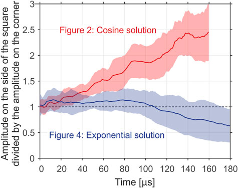
FIGURE 5. Mean ratios between the maximum amplitude in the middle of the sides of the square and the maximum amplitude in the corners of the square as a function of time after the moment of ultrasound excitation. A notable increase in the ratio is observed in the case of the cosine solution (Figure 2) due to the focusing effect. This effect is avoided in the case of the exponential solution (Figure 4).
The ratio between the maximum amplitude in the middle of the sides of the square and the maximum amplitude in the corners of the square increased almost linearly over time during the square wave expansion in the medium with the field of the temperature increase defined by Eq. 1 (cosine solution, Figure 2). It surpassed a value of 2 in the time interval between 100 µs and 120 µs after the wave excitation. In contrast, when the wave propagation velocity decreased exponentially in the radial direction (Figure 4), the ratio remained approximately constant at a value of 1. During the greater expansion of the square wave (110 µs and beyond after the excitation), the ratio even dropped below the value of 1. In other words, the mean value of maximal amplitudes in the corners was in this case higher than the mean value of maximal amplitudes in the middle of the sides of the square.
In addition to the focusing effect (wave divergence towards areas with lower wave velocity), the increase in amplitude in the middle of the sides of the squares in Figure 2 is also related to the fact that at the corresponding time instance square corners are further from the excitation point than the sides of the corners. Therefore, it is important to consider wave attenuation along the radial dimension. Attenuation in the directions of the four square corners in Figure 2 (cosine solution defined by Eq. 1) amounted to −421/mm, −421/mm, −414/mm, and −422/mm (up-left, down-left, down-right, and up-right). This was 1.66 times more compared to the attenuations in the direction of the four square sides: −255/mm, −255/mm, −276/mm, and −225/mm (up, left, down, and right). In contrast, spatial attenuation in the radial direction was approximately constant for all directions in the case of the exponential solution (Figure 4) for the square wave propagation. In the middle of the four square corners it was −210/mm, −208/mm, −219/mm, and −380/mm (up-left, down-left, down-right, and up-right), while in the middle of the four square sides it amounted to −265/mm, −240/mm, −218/mm, and −263/mm (up, left, down, and right). This yielded a mean difference by the mean factor of 1.02. This analysis confirmed our observation, that the propagation of a wave in the form of a square with a constant wave amplitude along its sides and corners is possible if the wave propagation velocity decreases exponentially in the radial direction as indicated in Figure 4A. Please refer to the Supplementary Material for more details about the dependency of the amplitude values on the radial position for each of the corners and square sides separately.
In the final example showing the capabilities of the reconfigurable medium, we demonstrate a two-dimensional pattern that transforms a circular wave into a spiral wave. This transformation is achieved by adjusting the wave velocity on a circular band located at a constant distance from the wave source. As observed in the infrared camera image (Figure 6A), the wave velocity is linearly decreased along this circular band until it reaches its minimum value at a specific angle. At this angle, which corresponds to the 12 o’clock direction or the position (x, y) = (0, 5) in Figure 6A, there is a discontinuous shift in the wave propagation velocity. This shift induces a 2π phase shift of the waves at a specific frequency (7.5 kHz in our case).
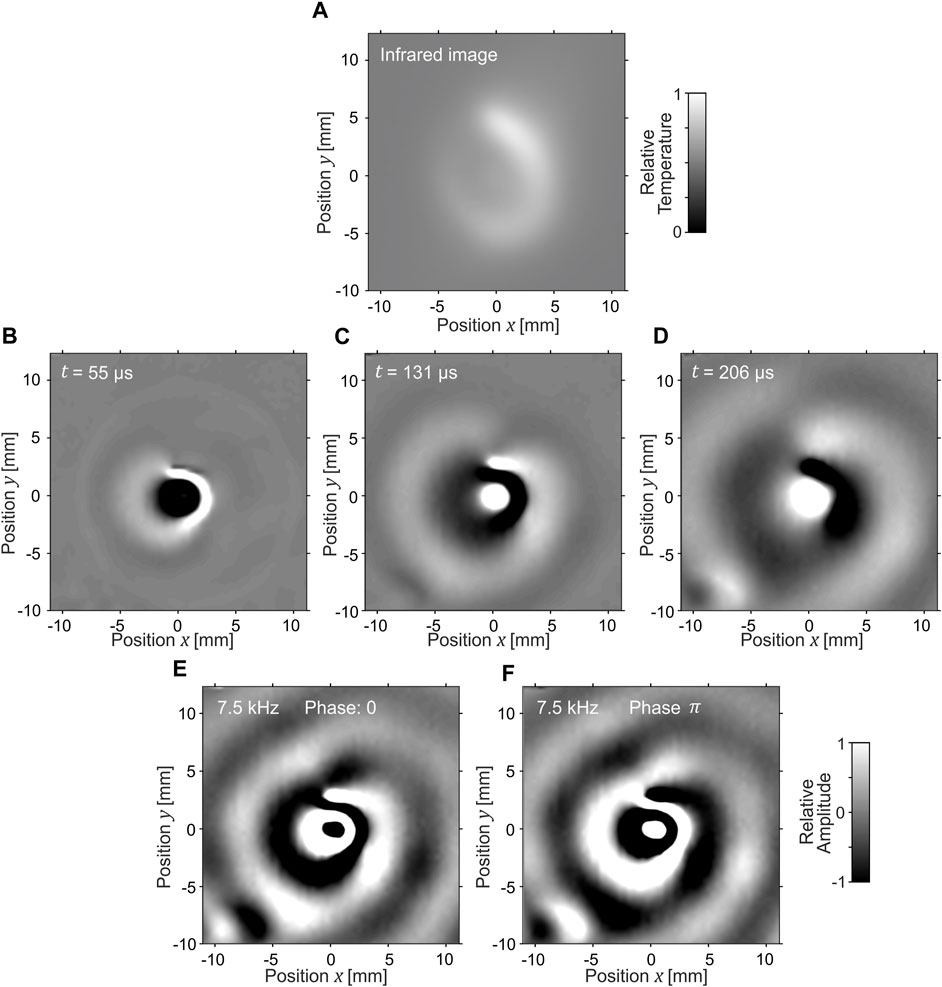
FIGURE 6. The heating pattern surrounding the excitation point transforms the circular wave into a spiral wave (A). The wave is delayed for one wavelength (at the corresponding frequency) in the 12 o’clock direction. Three time instances at the wave transition over this pattern (full frequency range) are shown in (B–D). At the chosen frequency, the wave propagates in the form of spirals in the far field (E, F) (Supplementary Material).
Figures 6B–D displays three time instances in the full frequency range as the wave travels through the region that transforms the circular planar wave into a spiral wave. It is noticeable that after the zero-order antisymmetric Lamb wave exits this region, it exhibits a break of the wavefront (phase shift) in the 12 o’clock direction of propagation. When we consider solely the frequency component with a wavelength equal to this phase shift (7.5 kHz), the waves propagate in the form of spirals in the far field outside of the region where the wave velocity was manipulated Figures 6E, F. An interesting wave behavior emerges during the transition from a circular to a spiral wave. At the point where the wave velocity shifts, the faster wavefront catches up with the slower one (12 o’clock direction from the origins of Figures 6E, F).
4 Discussion and conclusion
We have demonstrated a method that enables two-dimensional manipulation of Lamb wave propagation velocity. With this method, we conducted experimental studies to explore the feasibility of wave propagation in the form of squares and spirals. The experimental results were compared to numerical simulations.
We demonstrated that there is a fundamental physical limit in achieving wave propagation in the form of squares: wave lensing causes energy to concentrate towards the areas with decreased wave velocity, specifically, the center points of the square’s sides. Consequently, there is a lack of wave energy in the corners of the square.
We propose two alternatives for achieving wave propagation in the form of squares with constant energy along the sides of the square. The first solution is to make the wave rotate as it expands, while the second solution is to exponentially slow down the expansion of the square wave. The latter is the only two-dimensional distribution of wave propagation velocity that enable the propagation of square waves (no rotation) with approximately equal amplitude along the sides of the square. In the last example, we show that using the demonstrated reconfigurable medium, it is possible to transform circular planar wave into a spiral wave.
An alternative group of materials with reconfigurable Young’s modulus is based on photo-responsive liquid-crystal polymers (White et al., 2008; Iqbal and Samiullah, 2013). They offer the advantage that their energy can be controlled directly by illuminating light. This would result in shorter transition times compared to the SMP, where a new thermal equilibrium needs to be regained after each modification of the heating pattern.
The introduced method for wavefront shaping of Lamb waves can find applications for efficient energy transport, for example, by concentrating the energy of a vibrating structure (industrial machine, vehicle, or similar) at the point where it can be efficiently harvested. Furthermore, the tunable medium can be used for the purpose of imaging mechanical properties of plates (used as a material for safety-critical structures), where Lamb waves could be guided in an optimal way to most efficiently extract the targeted information, for example, about the production quality. Finally, a similar experimental platform can be used to generate large datasets of ultrasonic signals, contributing to the improvement of machine learning algorithms for product quality classification (Rus and Fleury, 2023). In this application, the presence of a defect is simulated by changing mechanical properties using a heating laser.
Data availability statement
The raw data supporting the conclusion of this article will be made available by the authors, without undue reservation.
Author contributions
JR: Conceptualization, Data curation, Formal Analysis, Investigation, Methodology, Project administration, Software, Visualization, Writing–original draft, Writing–review and editing. AB: Conceptualization, Formal Analysis, Software, Validation, Writing–review and editing. RF: Conceptualization, Funding acquisition, Investigation, Methodology, Project administration, Supervision, Validation, Writing–review and editing.
Funding
The author(s) declare financial support was received for the research, authorship, and/or publication of this article. The research was financially supported by the École Polytechnique Fédérale de Lausanne.
Acknowledgments
The authors acknowledge all the group members of the Laboratory of Wave Engineering.
Conflict of interest
The authors declare that the research was conducted in the absence of any commercial or financial relationships that could be construed as a potential conflict of interest.
The author(s) declared that they were an editorial board member of Frontiers, at the time of submission. This had no impact on the peer review process and the final decision.
Publisher’s note
All claims expressed in this article are solely those of the authors and do not necessarily represent those of their affiliated organizations, or those of the publisher, the editors and the reviewers. Any product that may be evaluated in this article, or claim that may be made by its manufacturer, is not guaranteed or endorsed by the publisher.
Supplementary material
The Supplementary Material for this article can be found online at: https://www.frontiersin.org/articles/10.3389/facou.2023.1337837/full#supplementary-material
References
Apffel, B., and Fort, E. (2022). Frequency conversion cascade by crossing multiple space and time interfaces. Phys. Rev. Lett. 128 (6), 064501. doi:10.1103/PhysRevLett.128.064501
Beckers, J. M. (1993). Adaptive optics for astronomy: principles, performance, and applications. Annu. Rev. Astronomy Astrophysics 31 (1), 13–62. doi:10.1146/annurev.aa.31.090193.000305
Booth, M. J. (2007). Adaptive optics in microscopy. Philosophical Trans. R. Soc. A Math. Phys. Eng. Sci. 365 (1861), 2829–2843. doi:10.1098/rsta.2007.0013
Bordyugov, G., and Engel, H. (2007). Continuation of spiral waves. Phys. D. Nonlinear Phenom. 228 (1), 49–58. doi:10.1016/j.physd.2007.02.005
Chen, L., Nie, Q. F., Ruan, Y., and Cui, H. Y. (2020). Thermal sensing metasurface with programmable wave-front manipulation. J. Appl. Phys. 128 (7), 075105. doi:10.1063/5.0013008
Chen, Z., Shao, S., Negahban, M., and Li, Z. (2019). Tunable metasurface for acoustic wave redirection, focusing and source illusion. J. Phys. D Appl. Phys. 52 (39), 395503. doi:10.1088/1361-6463/ab2abd
Davidenko, J. M., Pertsov, A. V., Salomonsz, R., Baxter, W., and Jalife, J. (1992). Stationary and drifting spiral waves of excitation in isolated cardiac muscle. Nature 355 (6358), 349–351. doi:10.1038/355349a0
Dupré, M., del Hougne, P., Fink, M., Lemoult, F., and Lerosey, G. (2015). Wave-field shaping in cavities: waves trapped in a box with controllable boundaries. Phys. Rev. Lett. 115 (1), 017701. doi:10.1103/PhysRevLett.115.017701
Fayyaz, Z., Mohammadian, N., Reza Rahimi Tabar, M., Manwar, R., and Avanaki, K. (2019). A comparative study of optimization algorithms for wavefront shaping. J. Innovative Opt. Health Sci. 12 (04), 1942002. doi:10.1142/S1793545819420021
Feng, Q., Yang, F., Xu, X., Zhang, B., Ding, Y., and Liu, Q. (2019). Multi-objective optimization genetic algorithm for multi-point light focusing in wavefront shaping. Opt. Express 27 (25), 36459–36473. doi:10.1364/OE.27.036459
Firouzeh, A., Salerno, M., and Paik, J. (2017). Stiffness control with shape memory polymer in underactuated robotic origamis. IEEE Trans. Robotics 33 (4), 765–777. doi:10.1109/TRO.2017.2692266
Frazier, B. W., Antonsen, T. M., Anlage, S. M., and Ott, E. (2020). Wavefront shaping with a tunable metasurface: creating cold spots and coherent perfect absorption at arbitrary frequencies. Phys. Rev. Res. 2 (4), 043422. doi:10.1103/PhysRevResearch.2.043422
Hampson, K. M., Turcotte, R., Miller, D. T., Kurokawa, K., Males, J. R., Ji, N., et al. (2021). Adaptive optics for high-resolution imaging. Nat. Rev. Methods Prim. 1 (1), 68. doi:10.1038/s43586-021-00066-7
Hermann, S., and Gottwald, G. A. (2010). The large core limit of spiral waves in excitable media: a numerical approach. SIAM J. Appl. Dyn. Syst. 9 (2), 536–567. doi:10.1137/090780055
Iqbal, D., and Samiullah, M. H. (2013). Photo-responsive shape-memory and shape-changing liquid-crystal polymer networks. Materials 6 (1), 116–142. doi:10.3390/ma6010116
Islam, M. S., Nakamura, T., Cho, Y.-H., and Mizutani, N. (2023). Investigation of the spiral wave generation and propagation on a numerical circular wave tank model. J. Mar. Sci. Eng. 11 (2), 388. doi:10.3390/jmse11020388
Kaina, N., Dupré, M., Lerosey, G., and Fink, M. (2014). Shaping complex microwave fields in reverberating media with binary tunable metasurfaces. Sci. Rep. 4 (1), 6693. doi:10.1038/srep06693
Katz, O., Small, E., Bromberg, Y., and Silberberg, Y. (2011). Focusing and compression of ultrashort pulses through scattering media. Nat. Photonics 5 (6), 372–377. doi:10.1038/nphoton.2011.72
Kyutoku, K., Shibata, M., and Taniguchi, K. (2021). Coalescence of black hole–neutron star binaries. Living Rev. Relativ. 24 (1), 5. doi:10.1007/s41114-021-00033-4
Li, T.-C., Gao, X., Zheng, F.-F., Pan, D.-B., Zheng, B., and Zhang, H. (2017). A theory for spiral wave drift induced by ac and polarized electric fields in chemical excitable media. Sci. Rep. 7 (1), 8657. doi:10.1038/s41598-017-09092-6
Li, Y. B., Li, L. L., Xu, B. B., Wu, W., Wu, R. Y., Wan, X., et al. (2016). Transmission-type 2-bit programmable metasurface for single-sensor and single-frequency microwave imaging. Sci. Rep. 6 (1), 23731. doi:10.1038/srep23731
Lin, Z., Pan, X., Yao, J., Wu, Y., Wang, Z., Zhang, D., et al. (2021). Characterization of orbital angular momentum applying single-sensor compressive imaging based on a microwave spatial wave modulator. IEEE Trans. Antennas Propag. 69 (10), 6870–6880. doi:10.1109/TAP.2021.3070067
Liu, L., Ma, K., Qu, Y., He, Q., Shao, R., Chen, C., et al. (2021). High-contrast light focusing through scattering media with multi-pixel encoding. Appl. Phys. Express 14 (9), 092009. doi:10.35848/1882-0786/ac200e
Ma, G., Fan, X., Sheng, P., and Fink, M. (2018). Shaping reverberating sound fields with an actively tunable metasurface. Proc. Natl. Acad. Sci. 115 (26), 6638–6643. doi:10.1073/pnas.1801175115
Mosk, A. P., Lagendijk, A., Lerosey, G., and Fink, M. (2012). Controlling waves in space and time for imaging and focusing in complex media. Nat. Photonics 6 (5), 283–292. doi:10.1038/nphoton.2012.88
Prat-Camps, J., Christopoulos, G., Hardwick, J., and Subramanian, S. (2020). A manually reconfigurable reflective spatial sound modulator for ultrasonic waves in air. Adv. Mater. Technol. 5 (8), 2000041. doi:10.1002/admt.202000041
Pretorius, F. (2005). Evolution of binary black-hole spacetimes. Phys. Rev. Lett. 95 (12), 121101. doi:10.1103/PhysRevLett.95.121101
Rus, J., and Fleury, R. (2023). Reduced training data for robust ultrasound signal interpretation by neural networks. PREPRINT (Version 1) available at Research Square. doi:10.21203/rs.3.rs-3639688/v1
Tay, J. W., Lai, P., Suzuki, Y., and Wang, L. V. (2014). Ultrasonically encoded wavefront shaping for focusing into random media. Sci. Rep. 4 (1), 3918. doi:10.1038/srep03918
Tian, Z., Shen, C., Li, J., Reit, E., Bachman, H., Socolar, J. E. S., et al. (2020). Dispersion tuning and route reconfiguration of acoustic waves in valley topological phononic crystals. Nat. Commun. 11 (1), 762. doi:10.1038/s41467-020-14553-0
Vellekoop, I. M., and Mosk, A. P. (2007). Focusing coherent light through opaque strongly scattering media. Opt. Lett. 32 (16), 2309–2311. doi:10.1364/OL.32.002309
Vellekoop, I. M., and Mosk, A. P. (2008). Phase control algorithms for focusing light through turbid media. Opt. Commun. 281 (11), 3071–3080. doi:10.1016/j.optcom.2008.02.022
Wang, X.-L., Yang, J., Liang, B., and Cheng, J.-C. (2019). Tunable annular acoustic metasurface for transmitted wavefront modulation. Appl. Phys. Express 13 (1), 014002. doi:10.7567/1882-0786/ab59a5
White, T. J., Tabiryan, N. V., Serak, S. V., Hrozhyk, U. A., Tondiglia, V. P., Koerner, H., et al. (2008). A high frequency photodriven polymer oscillator. Soft Matter 4 (9), 1796–1798. doi:10.1039/B805434G
Yu, H., Yao, Z., Sui, X., Gu, G., and Chen, Q. (2022). Focusing through disturbed multimode optical fiber based on self-adaptive genetic algorithm. Optik 261, 169129. doi:10.1016/j.ijleo.2022.169129
Keywords: reconfigurable medium, adaptive structures, lamb waves, active media, wavefront shaping
Citation: Rus J, Bossart A and Fleury R (2024) Optothermal shaping of lamb waves with square and spiral phase fronts. Front. Acoust. 1:1337837. doi: 10.3389/facou.2023.1337837
Received: 13 November 2023; Accepted: 22 December 2023;
Published: 15 January 2024.
Edited by:
Stefano Laureti, University of Calabria, ItalyReviewed by:
Thomas Pezeril, UMR6251 Institut de Physique de Rennes (IPR), FranceZhongtao Hu, Beihang University, China
Copyright © 2024 Rus, Bossart and Fleury. This is an open-access article distributed under the terms of the Creative Commons Attribution License (CC BY). The use, distribution or reproduction in other forums is permitted, provided the original author(s) and the copyright owner(s) are credited and that the original publication in this journal is cited, in accordance with accepted academic practice. No use, distribution or reproduction is permitted which does not comply with these terms.
*Correspondence: Janez Rus, janez.rus@tum.de; Romain Fleury, romain.fleury@epfl.ch
 Janez Rus
 Aleksi Bossart
 Romain Fleury