
94% of researchers rate our articles as excellent or good
Learn more about the work of our research integrity team to safeguard the quality of each article we publish.
Find out more
ORIGINAL RESEARCH article
Front. Phys., 29 September 2020
Sec. Medical Physics and Imaging
Volume 8 - 2020 | https://doi.org/10.3389/fphy.2020.567738
This article is part of the Research TopicApplied Nuclear Physics at AcceleratorsView all 57 articles
 Galen Aymar1Tobias Becker2
 Stewart Boogert3Marco Borghesi4
 Robert Bingham1,5Ceri Brenner1Philip N. Burrows6Oliver C. Ettlinger7
 Titus Dascalu8Stephen Gibson3Timothy Greenshaw9Sylvia Gruber10Dorothy Gujral11
 Claire Hardiman11
 Jonathan Hughes9W. G. Jones8,12
 Karen Kirkby13Ajit Kurup8*Jean-Baptiste Lagrange1
 Kenneth Long1,8Wayne Luk8John Matheson1Paul McKenna5,14
 Ruth McLauchlan11Zulfikar Najmudin7Hin T. Lau8
 Jason L. Parsons15,16Jaroslaw Pasternak1,8Juergen Pozimski1,8
 Kevin Prise17
 Monika Puchalska18Peter Ratoff14,19
 Giuseppe Schettino20,21
 William Shields3Susan Smith22John Thomason1Stephen Towe23Peter Weightman8Colin Whyte5Rachel Xiao24
The “Laser-hybrid Accelerator for Radiobiological Applications,” LhARA, is conceived as a novel, flexible facility dedicated to the study of radiobiology. The technologies demonstrated in LhARA, which have wide application, will be developed to allow particle-beam therapy to be delivered in a new regimen, combining a variety of ion species in a single treatment fraction and exploiting ultra-high dose rates. LhARA will be a hybrid accelerator system in which laser interactions drive the creation of a large flux of protons or light ions that are captured using a plasma (Gabor) lens and formed into a beam. The laser-driven source allows protons and ions to be captured at energies significantly above those that pertain in conventional facilities, thus evading the current space-charge limit on the instantaneous dose rate that can be delivered. The laser-hybrid approach, therefore, will allow the radiobiology that determines the response of tissue to ionizing radiation to be studied with protons and light ions using a wide variety of time structures, spectral distributions, and spatial configurations at instantaneous dose rates up to and significantly beyond the ultra-high dose-rate “FLASH” regime. It is proposed that LhARA be developed in two stages. In the first stage, a programme of in vitro radiobiology will be served with proton beams with energies between 10 and 15 MeV. In stage two, the beam will be accelerated using a fixed-field alternating-gradient accelerator (FFA). This will allow experiments to be carried out in vitro and in vivo with proton beam energies of up to 127 MeV. In addition, ion beams with energies up to 33.4 MeV per nucleon will be available for in vitro and in vivo experiments. This paper presents the conceptual design for LhARA and the R&D programme by which the LhARA consortium seeks to establish the facility.
It is well-established that radiation therapy (RT) is an effective treatment for many types of cancer. Most treatments are delivered by machines that accelerate electrons which are then used to produce a beam of high-energy photons (X-rays) which are directed at a tumor to kill cancer cells. However, healthy tissue anywhere in the path of the photon beam is also irradiated and so can be damaged. Modern X-ray therapy is able to reduce this damage by using several beams at different angles. Recent years have seen the use of a new type of machine in which protons are accelerated to produce proton beams (rather than photon beams) which are directed at a tumor. These proton beams can be arranged to deposit almost all of their energy in a small volume within a tumor so they cause little damage to healthy tissue; a major advantage over photon beams. But proton machines are large and expensive, so there is a need for the development of proton machines that are smaller, cheaper and more flexible in how they can be used. The LhARA project is aimed at the development of such proton machines using a new approach based on high power lasers. Such new machines could also make it easier to deliver the dose in very short high-intensity pulses and as a group of micro-beams—exciting recent research has shown that this brings improved effectiveness in killing cancer cells while sparing healthy tissue. The technology to be proved in LhARA should enable a course of RT to be delivered in days rather than weeks. Scientifically, there is a need to understand better the basic processes by which radiation interacts with biological matter to kill cancer cells—the investigation of these processes involves physics as well as biology. Thus the most important aim of LhARA is to pursue this radiobiological research in new regimens and from this to develop better treatments. LhARA will also pursue technological research into laser-hybrid accelerators.
Cancer is the second most common cause of death globally [1]. In 2018, 18.1 million new cancer cases were diagnosed, 9.6 million people died of cancer-related disease, and 43.8 million people were living with cancer [2, 3]. It is estimated that 26.9 million life-years could be saved in low- and middle-income countries if radiotherapy capacity could be scaled up [4]. Novel techniques incorporated in facilities that are at once robust, automated, efficient, and cost-effective are required to deliver the required scale-up in provision.
Radiation therapy a cornerstone of cancer treatment, is used in over 50% of cancer patients [5]. The most frequently used types of RT employ photon or electron beams with MeV-scale energies. Proton and ion beams offer substantial advantages over X-rays because the bulk of the beam energy is deposited in the Bragg peak. This allows dose to be conformed to the tumor while sparing healthy tissue and organs at risk. The benefits of proton and ion-beam therapy (PBT) are widely recognized. PBT today is routinely delivered in fractions of ~ 2 Gy per day over several weeks; each fraction being delivered at a rate of ≲5 Gy/min deposited uniformly over the target treatment volume. There is evidence of therapeutic benefit when dose is delivered at ultra-high rate, ≳40 Gy/s, in “FLASH” RT [6–10] or when multiple micro-beams with diameter <1 mm distributed over a grid with inter-beam spacing ~ 3 mm are used [11–16]. However, the radiobiological mechanisms by which the therapeutic benefit is generated using these approaches are not entirely understood.
LhARA, the Laser-hybrid Accelerator for Radiobiological Applications, is conceived as the new, highly flexible, source of radiation that is required to explore the mechanisms by which the biological response to ionizing radiation is determined by the physical characteristics of the beam. A high-power pulsed laser will be used to drive the creation of a large flux of protons or ions which are captured and formed into a beam by strong-focusing plasma lenses. The plasma (Gabor) lenses provide the same focusing strength as high-field solenoids at a fraction of the cost. Rapid acceleration will be performed using a fixed-field alternating-gradient accelerator (FFA), thereby preserving the unique flexibility in the time, energy, and spatial structure of the beam afforded by the laser-driven source.
The LhARA facility may be developed in two stages. In the first stage, the laser-driven beam, captured and transported using plasma lenses and bending magnets, will serve a programme of in vitro radiobiology with proton beams of energy of up to 15 MeV. In stage two, the beam will be accelerated using an FFA. This will allow experiments to be carried out in vitro and in vivo with proton-beam energies of up to 127 MeV. Ion beams (including C6+) with energies up to 33.4 MeV per nucleon will also be available.
The laser pulse that initiates the production of protons or ions at LhARA may be triggered at a repetition rate of up to 10 Hz. The time structure of the beam may therefore be varied to interrupt the chemical and biological pathways that determine the biological response to ionizing radiation using 10 ns to 40 ns long proton or ion bunches repeated at intervals as small as 100 ms. The technologies chosen to capture, transport, and accelerate the beam in LhARA ensure that this unique capability is preserved. The LhARA beam may be used to deliver an almost uniform dose distribution over a circular area with a maximum diameter of between 1 and 3 cm. Alternatively, the beam can be focused to a spot with diameter of ~ 1 mm.
The technologies that will be developed in LhARA have the potential to make PBT available to the many. The laser-hybrid approach will allow radiobiological studies and eventually radiotherapy to be carried out in completely new regimens, delivering a variety of ion species in a broad range of time structures, spectral distributions, and spatial configurations at instantaneous dose rates up to and potentially significantly beyond the current ultra-high dose-rate “FLASH” regime.
The “pre Conceptual Design Report” (pre-CDR) for LhARA [17] lays the foundations for the development of full conceptual and technical designs for the facility. The pre-CDR also contains a description of the R&D that is required to demonstrate the feasibility of critical LhARA components and systems. This paper presents a summary of the contents of the pre-CDR and lays out the vision of the LhARA consortium.
RT delivered using protons and ions, PBT, has the potential to overcome some of the fundamental limitations of X-rays in cancer treatment through the targeted delivery of the radiation dose [18]. The Particle Therapy Co-Operative Group (PTCOG) currently lists 90 proton therapy facilities and 12 carbon ion therapy facilities worldwide, located predominantly in high-income countries [19]. Low- and middle-income countries (LMIC) are relatively poorly served, indeed nearly 70% of cancer patients globally do not have access to RT [5].
The efficacy of proton and ion beams is characterized by their relative biological effectiveness (RBE) in comparison to a reference photon beam. The treatment-planning software that is in use in the clinic today assumes an RBE value for protons of 1.1 [20], meaning that, compared to X-rays, a lower dose of protons is needed to produce the same therapeutic effect. However, the rapid rise in the linear energy transfer (LET) at the Bragg peak leads to significant uncertainties in the RBE. Furthermore, it is known that RBE depends strongly on many factors, including particle energy, dose, dose rate, the degree of hypoxia, and tissue type [21]. Indeed, RBE values from 1.1 to over 3 have been derived from in vitro clonogenic-survival assay data following proton irradiation of cultured cell lines derived from different tumors [21–23]. RBE values of ~ 3 are accepted for high-LET carbon-ion irradiation, although higher values have been reported [24]. RBE uncertainties for carbon and other ion species are at least as large as they are for protons. These uncertainties can lead to an incorrect estimation of the dose required to treat a particular tumor. Overestimation can lead to the damage of healthy tissue, while an underestimate can lead to the tumor not being treated sufficiently for it to be eradicated.
The radiotherapeutic effect is caused largely by irreparable damage to the cell's DNA. The spectrum of DNA damage induced within tumor cells changes in response to differences in RBE. Larger RBE values, corresponding to higher LET, can increase the frequency and complexity of DNA damage, in particular causing DNA double-strand breaks (DSB) and complex DNA damage (CDD), where multiple DNA lesions are induced in close proximity [25, 26]. These DNA lesions are a major contributor to radiation-induced cell death as they represent a significant barrier to the cellular DNA-repair machinery [25]. However, a number of other biological factors contribute to varying RBE in specific tumors, including the intrinsic radio-sensitivity of the tissue, the level of oxygenation (hypoxia), the growth and re-population characteristics, and the associated tumor micro-environment. Consequently, there is still significant uncertainty in the precise radiobiological mechanisms that arise and how these mechanisms determine the impact of PBT. Detailed systematic studies of the biophysical effects of the interaction of protons and ions, under different physical conditions, with different tissue types will provide important information on RBE variation and could enable enhanced patient treatment-planning algorithms to be devised. In addition, studies examining the impact of combination therapies with PBT (e.g., targeting the DNA damage response, hypoxia signaling mechanisms and also the tumor micro-environment) are currently sparse; performing these studies will therefore provide input vital to the development of future personalized patient-therapy strategies using PBT.
Extending the range of beam characteristics used in PBT delivery may have significant therapeutic benefits. Delivery of RT at high dose rates has led to noticeably reduced lung fibrosis in mice, reduced skin toxicity in mini-pigs, and reduced side-effects in cats with nasal squamous-cell carcinoma, effects currently thought to be mediated via local oxygen depletion [10, 27]. In fact, the first patient with CD30+ T-cell cutaneous lymphoma has been safely treated with electrons delivered at FLASH dose rates [28]. In addition, therapeutic benefit has been demonstrated with the use of multiple micro-beams [12]. However, there is still significant uncertainty regarding the thresholds and the radiobiological mechanisms underlying these effects. Extensive further study both in vitro and in appropriate in vivo models is required.
The LhARA facility will provide access to proton and stable ion beams, provide a wide variety of temporal, spatial, and spectral fractionation schemes, and deliver reliable and reproducible biological data with fewer constraints than at current clinical centers. LhARA will allow direct radiobiological comparisons of the effects of different charged particles at different energies and dose rates and enable unique mechanistic studies (e.g., examination of the oxygen depletion hypothesis for FLASH). In addition, LhARA will enable exhaustive evaluations of RBE using more complex end-points (e.g., angiogenesis and inflammation) in addition to routine survival measurements. The ability to evaluate charged particles in conjunction with other therapies (immunotherapy and chemotherapy) and to perform in vivo experiments with the appropriate animal models is of great importance given the current lack of evidence in these areas. LhARA therefore has the potential to provide the radiobiological data required to improve clinical practice.
The simulations of LhARA presented in this document have been used to estimate the dose delivered as a function of energy for protons and carbon ions. These simulations, described in sections 3.3 and 3.4, show instantaneous particle rates of the order of 109 particles per shot can be achieved, corresponding to average dose rates of up to ≳120 Gy/s for protons and ≳700 Gy/s for carbon ions. These estimates are based on the baseline specifications for LhARA.
High-power lasers have previously been proposed as an alternative to conventional proton and carbon-ion facilities for radiotherapy [29–32]. Laser-driven sources have also been proposed as the basis for electron, proton and ion-beams for radiobiology [33–40]. While a number of cell irradiation experiments have been conducted with laser-accelerated ions [37, 38, 41, 42], these have been limited in scope to a single-shot configuration. More recent projects (e.g., A-SAIL [43], ELI [44], and SCAPA [45]) will also investigate radiobiological effects using laser-driven ion beams. These studies will also address various technological issues [42, 46–49].
A beam line to provide ion-driven beams for multi-disciplinary applications, ELIMAIA (ELI Multidisciplinary Applications of laser-Ion Acceleration) is being brought into operation at the Extreme Light Infrastructure (ELI) [50, 51]. This beam line will include the “ELI MEDical and multidisciplinary applications” (ELIMED) beam line which will allow radiobiological investigations to be carried out [46, 50, 52–55]. LhARA is distinguished from this facility in that the energy at which the beam will be captured has been chosen to maximize the shot-to-shot stability of the particle flux.
Protons and ions at conventional facilities are captured at energies of several tens of keV. At such low energies, the mutual repulsion of the particles, the “space-charge effect,” limits the maximum instantaneous dose rate. The laser-driven source allows protons and ions to be captured at significantly higher energies, thus evading the current space-charge limit. Rapid acceleration will be performed using a fixed-field alternating-gradient accelerator (FFA), thereby preserving the unique flexibility in the time, energy, and spatial structure of the beam afforded by the laser-driven source. Modern lasers are capable of delivering a Joule of energy in pulses that are tens of femtoseconds in length at repetition rates of ≳10 Hz. Laser-driven ion sources create beams that are highly divergent, have a large energy spread, and an intensity that can vary by up to 25% pulse-to-pulse [56]. These issues are addressed in the LhARA conceptual design through the use of Gabor lenses to provide strong focusing and to allow energy selection. In addition, sophisticated instrumentation will be used in a fast feedback-and-control system to ensure that the dose delivered is both accurate and reproducible. This approach will allow multiple ion species, from proton to carbon, to be produced from a single laser by varying the target foil and particle-capture optics.
LhARA will prove the principle of the novel technologies required for the development of future therapy facilities. The legacy of the LhARA programme will therefore be: a unique facility dedicated to the development of a deep understanding of the radiobiology of proton and ion beams; and the demonstration in operation of technologies that will allow PBT to be delivered in completely new regimens.
The LhARA facility, shown schematically in Figure 1, has been designed to serve two end stations for in vitro radiobiology and one end station for in vivo studies. The principle components of Stage 1 of the LhARA accelerator are: the laser-driven proton and ion source; the matching and energy selection section; beam delivery to the low-energy in vitro end station; and the low-energy abort line. Stage 2 is formed by the injection line for the fixed-field alternating-gradient accelerator (FFA); the FFA; the extraction line; the high-energy abort line; beam delivery to the high-energy in vitro end station; and the transfer line to the in vivo end station. Proton beams with energies of between 10 and 15 MeV will be delivered directly from the laser-driven source to the low-energy in vitro end station via a transfer line. The high-energy in vitro end station and the in vivo end station will be served by proton beams with energy between 15 and 127 MeV and by ion beams, including C6+ with energies up to 33.4 MeV/u. The design parameters for the various components of LhARA are given in Tables 1, 2. The design of the LhARA facility is described in the sections that follow.
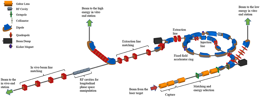
Figure 1. Schematic diagram of the LhARA beam lines. The particle flux from the laser-driven source is shown by the red arrow. The “Capture” section is followed by the “Matching and energy selection” sections, the beam is directed either into the 90° bend that takes it to the low-energy in vitro end station, toward the FFA injection line, or to the low-energy beam dump. Post-acceleration is performed using the FFA, on extraction from which the beam is directed either to the high-energy in vitro end station, the in vivo end station, or the high-energy beam dump. Gabor lenses are shown as orange cylinders, RF cavities as gray cylinders, octupole magnets as green discs, collimators as dark-green bars, dipole magnets are shown in blue, quadrupole magnets are shown in red, beam dumps (black rectangles) and kicker magnets are also shown.
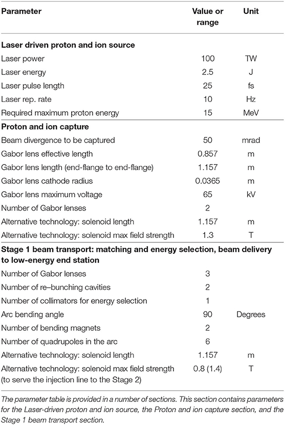
Table 1. Design parameters of the components of the LhARA facility.
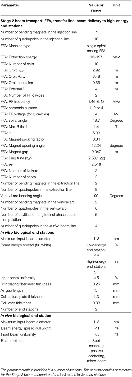
Table 2. Design parameters of the components of the LhARA facility.
A novel solution for proton and ion acceleration is to use a compact, flexible laser-driven source coupled to a state-of-the-art beam-transport line. This allows an accelerating gradient of ≳10 GV/m to be exploited at the laser-driven source. We propose to operate in the laser-driven sheath-acceleration regime [57–60] for ion generation. An intense, short laser pulse will be focused onto a target. The intense electric field generated on the front surface of the target accelerates the surface electrons, driving them into the material. Electrons which gain sufficient energy traverse the target, ionising the material as they go. A strong space-charge electric field, the “sheath,” is created as the accelerated electrons exit the rear surface of the target. This field in turn accelerates protons and ions present as contaminants on the surface. The sheath-acceleration scheme has been shown to produce ion energies >40 MeV/u at the highest laser intensities [56]. The maximum proton energy (Ep) scales with laser intensity (I) as, . The laser required to deliver a significant proton flux at 15 MeV is commercially available.
The distribution of proton and ion energies observed in laser-driven beams exhibits a sharp cut-off at the maximum energy and, historically, the flux of laser-accelerated ion beams has varied significantly shot-to-shot. To reduce these variations, the choice has been made to select particles from the plateau of the two-temperature energy spectrum of the laser-accelerated ion beam [61, 62]. This should enhance ion-beam stability and allow reproducible measurements to be carried out at ultra-high dose rates using a small number of fractions. To create the flux required in the plateau region, it is proposed that a 100 TW laser system is used. A number of commercial lasers are available that are capable of delivering > 2.5 J in pulses of duration < 25 fs, at 10 Hz with contrast better than 1010:1. Shot-to-shot stability of < 1% is promised, an important feature for stable ion-beam production.
Key to the operation of this configuration is a system that refreshes the target material at high repetition-rate in a reproducible manner. A number of schemes have been proposed for such studies, including high-pressure gases [63–65], cryogenic hydrogen ribbons [66–68], liquid sheets [69], and tape drives [70]. For LhARA, a tape drive based on the system developed at Imperial College London is proposed [56]. This system is capable of reliable operation at target thicknesses down to 5 μm, using aluminium or steel foils, and down to 18 μm using plastic tapes. Such tape-drive targets can be operated at high charge (up to 100 pC at 15 ± 1 MeV, i.e., > 109 protons per shot) and can deliver high-quality proton and ion fluxes at repetition rates of up to 10 Hz or greater.
The careful control of the tension of the tape in a tape-drive target is critical for reproducible operation. The tape must be stretched enough to flatten the surface, but not enough to cause plastic deformations. Surface flatness is important for a number of reasons. Rippling of the front surface modifies the laser absorption dramatically; uncharacterised rippling can make shot-to-shot variations significant and unpredictable [70]. Similarly, rear surface perturbations can modify the sheath field, resulting in spatial non-uniformities of the proton beam or suppression of the achievable peak energies. Tape drives with torsion control and monitoring to maintain a high-quality tape surface have been designed and operated in experiments at Imperial College London. The development of these targets continues with a view to the production of new, thinner tapes for improved ion generation and the creation of ion species other than protons and carbon. This is an active area of R&D that will continue with the development of LhARA.
The use of an electron cloud as a focusing element for charged-particle beams was first proposed by Gabor [71]. The electron cloud is confined within the lens using a long cylindrical anode placed within a uniform solenoid field (see Figure 2). Such a configuration is commonly known as a “Penning trap” and has found wide application in many fields [72]. Variations on the Penning trap where axial apertures in the cathodes are introduced, such as the Penning-Malmberg trap [73, 74] are attractive for beam-based applications due to the excellent access provided to the plasma column.
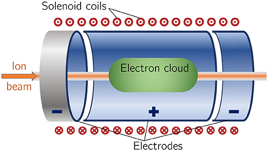
Figure 2. Schematic diagram of a Penning-Malmberg trap of the type proposed for use in the Gabor lenses to be used in LhARA. The solenoid coils, and the direction of current flow, are indicated by the red circles (the central dots indicate current emerging from the picture, crosses current entering it). The confining electrostatic potential is provided using a central cylindrical anode and two cylindrical negative end electrodes. The ion beam enters on-axis from the left and the electron cloud is indicated by the green shaded area.
The focal length of a Gabor lens of length l is given in terms of the electron number density by [76]:
where e is the magnitude of the electric charge of the electron, ne is the number density of the electrons confined within the lens, ϵ0 the permittivity of free space, and U the kinetic energy of the particle beam. The desired focusing strength determines ne which in turn allows the anode voltage and magnetic-field strength to be calculated [75, 76]. The focal lengths required to capture the proton and ion beams at LhARA have been chosen such that the necessary electron number densities lie well within the range achieved in published experiments.
For a given focal length, the magnetic field strength required in the Gabor lens is smaller than that of a solenoid that would give equivalent focusing. In the non-relativistic approximation, the relationship between the magnetic field strength in the Gabor lens, BGBL, and the equivalent solenoid, Bsol, is given by [76]:
where Z is the charge state of the ions. In the case of a proton beam, the reduction factor is 43. This means the cost of the solenoid for a Gabor lens can be significantly lower than the cost of a solenoid of equivalent focusing strength.
Instability of the electron cloud is a concern in the experimental operation of a Gabor lens; azimuthal beam disruption due to the diocotron instability has been observed and described theoretically [77]. Theory indicates that the diocotron instability is most problematic under well-defined geometric conditions. The reliable operation of a Gabor lens in a regime free from this instability has yet to be demonstrated. Gabor lenses promise very strong focusing, simple construction, and low magnetic field, all attractive features for LhARA. However, these attractive features come at the cost of relatively high voltage operation (≳50 kV) and possible vulnerability to instability.
With reliable operation of Gabor lenses as yet unproven, we plan a two-part experimental and theoretical programme of research to investigate their suitability. Initial work will include: the theoretical study of lens stability using a full 3D particle-in-cell code, such as VSIM [78]; and the development of electron-density diagnostics based on interferometric measurement of the resulting refractive-index change. A test Gabor lens will be constructed to allow validation of both the simulation results and a new diagnostic tool using an alpha emitter as a proxy for the LhARA beam. In addition, the initial investigation will include the design of an injection system to fill the lens with the required electron cloud. Should it prove impossible to produce a suitable Gabor lens, it will be necessary to use high-field solenoids to produce the equivalent focusing effect.
The beam transport line to the low-energy in vitro end station must produce a uniform dose distribution at the cell layer. Beam losses must be minimized for radiation safety and to maximize the dose that can be delivered in a single shot. The transport line has been designed to minimize regions in which the beam is brought to a focus to reduce the impact of space-charge forces on the beam phase-space. An optical solution was initially developed using Beamoptics [79] and MADX [80]. Accurate estimation of the performance of the beam line requires the inclusion of space-charge forces and particle-matter interactions. Performance estimation was therefore performed using Monte Carlo particle-tracking from the ion source to the end station. BDSIM [81], which is based on the GEANT4 toolkit, was used for the simulation of energy deposition arising from beam interactions with the material in the accelerator and the end station. GPT [82] was used for evaluating the full 3D impact of space-charge effects.
An idealized Gaussian beam was generated with a spot size of 4 μm FWHM, an angular divergence of 50 mrad, 35 fs FWHM bunch length, and an energy spread of 1 × 10⁻⁶ MeV. The maximum estimated bunch charge is 1 × 10⁹ protons. The presence of a substantial electron flux produced from the laser target compensates the high proton charge density in the vicinity of the ion-production point. To approximate the partial space-charge compensation in this region, it was assumed that co-propagating electrons would fully compensate the space-charge forces over the first 5 cm of beam propagation. Beyond this, the proton beam was assumed to have separated from the co-propagating electrons sufficiently for space-charge to become a significant effect and cause emittance growth. Therefore, a further 5 cm drift was simulated including space-charge forces. At a distance of 10 cm from the ion source, the beam is at the exit of the laser-target vessel. The kinematic distributions of ions in the beam were stored at this point and passed to the relevant BDSIM and GPT simulations of the downstream beam line.
The Stage 1 beam line, shown schematically in Figure 3, is composed of five sections: beam capture; matching and energy selection; beam shaping; vertical arc matching; and an abort line. The capture section uses two Gabor lenses to minimize the transverse momentum of particles in the beam. Beyond the capture section, an RF cavity permits control of the bunch length and manipulation of the longitudinal phase-space. A third Gabor lens then focuses the bunch to a small spot size after which a second RF cavity is located to provide further longitudinal phase-space manipulation. Two further Gabor lenses ensure the beam is again parallel before it enters the vertical 90° arc. All Gabor lenses have an inner radius of 3.65 cm and an effective length of 0.857 m. All lenses operate at a cathode voltage of <65 kV.
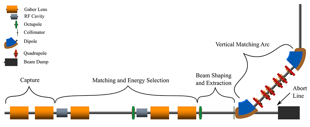
Figure 3. Beam transport for Stage 1 of LhARA visualized in BDSIM, showing five machine sections. The capture section is composed of two Gabor lenses (orange cylinders). The matching and energy selection section includes three Gabor lenses, two RF cavities (gray cylinders) and an octupole magnet (green disc). The beam shaping and extraction section includes a second octupole and a collimator (vertical dark-green bar). The vertical matching arc directs the beam into the low-energy in vitro end station and is composed of two 45° dipoles (blue and brown) and six quadrupoles (red). The total length of this beam line is 17.3 m.
The parallel beam that emerges from the final Gabor lens, provides significant flexibility for the inclusion of beam shaping and extraction systems. Beam uniformity will be achieved using octupole magnets to provide third-order focusing to perturb the first-order focusing of the Gabor lenses. Such schemes have been demonstrated in magnetic lattices in a number of facilities [83–85]. A suitable position for the first octupole was identified to be after the final Gabor lens where the beam is large; its effect on the beam is expected to be significant. Octupoles were only modeled in BDSIM as GPT does not have a standard component with an octupolar field. The typical rectangular transverse distribution resulting from octupolar focusing requires collimation to match the circular aperture through which the beam enters the end station. A collimator is therefore positioned at the start of the vertical arc. Further simulations are required to determine the optimum position of the second octupole and to evaluate the performance of the octopoles. The switching dipole which directs the beam to the injection line of the FFA in Stage 2 will be located between the second octupole and the collimator, requiring the octupole to be ramped down for Stage 2 operation.
The vertical arc uses transparent optics in an achromat matching section to ensure that the first-order transfer map through the arc is equivalent to the identity transformation and that any dispersive effects are canceled. A 2 m drift tube is added after the arc to penetrate the concrete shielding of the end station floor and to bring the beam to bench height. The abort line consists of a drift space followed by a beam dump. Ramping down the first vertical dipole causes the beam to enter the dump and prevents particle transportation to the end station.
The underlying physics of plasma-lens operation cannot be simulated in BDSIM or GPT. It can, however, be approximated using solenoid magnets of equivalent strength. RF cavity fields were not simulated.
To produce the results shown here, 10,000 particles were simulated, corresponding to the estimated maximum bunch charge of 1 × 10⁹ protons. Figure 4 shows excellent agreement between horizontal and vertical transverse beam sizes in BDSIM and MADX, verifying the beam line's performance in the absence of space-charge effects. Reasonable agreement between BDSIM and GPT is also seen when space-charge forces are included in GPT. Emittance growth is observed prior to the first solenoid, affecting the optical parameters throughout the machine. However, the resulting beam dimensions at the cell layer of 1.38 cm horizontally and 1.47 cm vertically are not significantly different from those in BDSIM. If needed, further adjustments of the Gabor lens and arc-quadrupole strengths may compensate for any space-charge effects. The transmission efficiency of the beam line is ~100%.
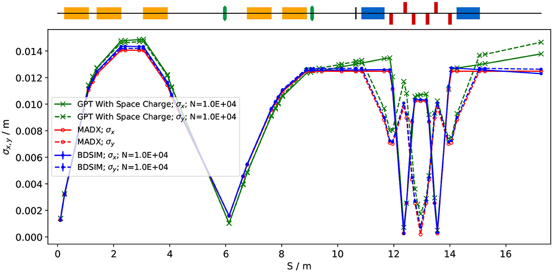
Figure 4. Horizontal (solid lines) and vertical (dashed lines) beam sizes through the in vitro beam transport, simulated including space-charge effects in GPT (green), and without space-charge in MADX (red) and BDSIM (blue).
The small bunch dimensions in both transverse planes at the focus after the third Gabor lens, where the energy selection collimator will be placed, could be of concern if the effect of space-charge has been underestimated. Similar bunch dimensions are achieved in the vertical arc. Here, however, quadrupolar focusing is confined to a single plane to mitigate possible further emittance growth.
To investigate beam uniformity, BDSIM simulations with and without octupoles and collimation for beam shaping were conducted. Each octopole was assumed to have a magnetic length of 0.1 m and pole-tip radius of 5 cm. The strength parameter, k3, of each octupole was arbitrarily set to 6, 000. A 2 cm thick iron collimator with a 40 mm diameter aperture was positioned 1.5 m downstream of the octupole. Figure 5 shows the beam phase-space and particle distributions at the Stage 1 end station for the transverse and longitudinal axes with and without beam shaping. Without octupoles, the spatial profile is Gaussian, as expected. Inclusion of the octupoles and collimation system improves beam uniformity. The total beam width is 3.58 cm horizontally and 3.46 cm vertically, which is sufficient to irradiate one well in a six-well cell-culture plate. Further optimization is required to improve uniformity whilst optimizing beam-line transmission, which is ~70% for the results presented in Figure 5.
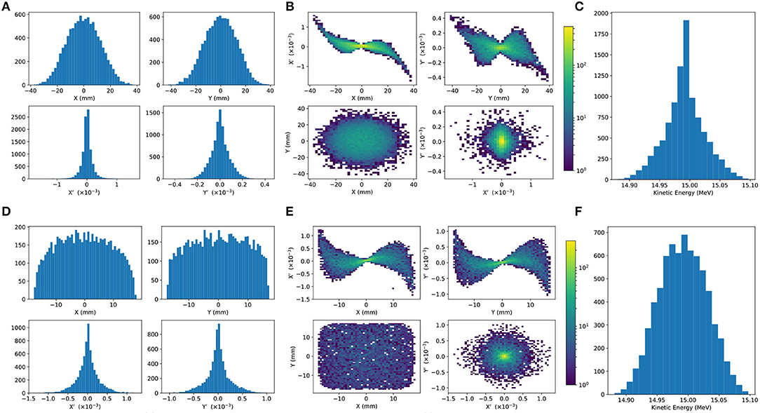
Figure 5. Beam phase space distributions at the end-station in the transverse plane, (X, Y); X′ and Y′ give the slope relative to the Z axis. The transverse phase space is shown in (A,B) for simulations without octupolar focusing and collimation, with the kinetic energy distribution shown in (C). The same phase space distributions simulated with the effect of octupoles and collimation are in figures (D–F).
An aberration can be seen in both transverse planes with and without beam shaping. This effect originates upstream of the octupoles in the solenoids used to approximate the Gabor lenses, and persists to the end station. The aberration is a concern, but is likely to change when the solenoids are replaced by full electromagnetic simulation of the Gabor lenses, at which point it will be further investigated.
The non-Gaussian energy distribution without beam shaping is a result of space-charge forces at the ion source; the distribution persists to the end station as no components which affect the longitudinal phase space were simulated. The Gaussian distribution seen with beam shaping reflects the effects of the collimation.
The proposed design is capable of delivering beams of the desired size to the in vitro end station. Space-charge effects affect the beam-transport performance but it is believed that these can be mitigated with minor adjustments to the Gabor lenses in the capture section. Initial studies indicate that a uniform beam can be delivered with further optimization of the octupoles and collimator.
To mitigate potential emittance growth from space-charge forces, an alternative beam line design was developed in which the final two Gabor lenses in the matching and energy selection section are replaced by four quadrupoles, limiting any bunch focusing to one plane at a time. The resulting machine is reduced in length to 15.4 m. Without space-charge effects, a beam width of 2.5 mm at the end station can be achieved. With space-charge, emittance growth prior to the first solenoid is once again observed leading to an increased beam size at the entrance of the first quadrupole, resulting in a spatially asymmetric and divergent beam at the end station. It is believed that the space-charge effects can be compensated by applying the same Gabor lens optimization as in the baseline design and adjusting the quadrupole settings to deliver beam parameters similar to those achieved in the absence of space charge. The alternative design provides a solution that is more resilient to space-charge effects than the baseline, however, only the lower bound on the desired beam size has been achieved so far. For this design, further optimization is required not only to improve optical performance but also to optimize octupole settings and to determine whether a beam with the desired uniformity can be delivered to the end station.
A fixed-field alternating-gradient accelerator (FFA), based on the spiral scaling principle [86–89], will be used to accelerate the beam in LhARA Stage 2 to obtain energies greater than the 15 MeV protons and 4 MeV/u carbon (C6+) ions delivered by the laser-driven source. FFAs have many advantages for both medical and radiobiological applications, such as: the capability to deliver high and variable dose; rapid cycling with repetition rates ranging from 10 to 100 Hz or beyond; and the ability to deliver various beam energies without the use of energy degraders. An FFA is relatively compact due to the use of combined function magnets, which lowers the overall cost compared to conventional accelerators capable of delivering beams at a variety of energies such as synchrotrons. Extraction can be both simple and efficient and it is possible for multiple extraction ports to be provided. Furthermore, FFAs can accelerate multiple ion species, which is very important for radiobiological experiments and typically very difficult to achieve with cyclotrons.
A typical FFA is able to increase the beam momentum by a factor of three, though a greater factor may be achieved. For LhARA, this translates to a maximum proton-beam energy of 127 MeV from an injected beam of 15 MeV. For carbon ions (C6+) with the same rigidity, a maximum energy of ~33.4 MeV/u can be produced.
The energy at injection into the FFA determines the beam energy at extraction. The injection energy will be changed by varying the focusing strengths in the Stage 1 beam line from the capture section through to the extraction line and the FFA ring. Appropriate adjustments to the frequency and phase of the RF in the FFA ring will also be made. This will allow the required energy slice from the broad spectrum produced at the laser-driven source to be captured and transported to the FFA. The FFA will then accelerate the beam, acting as a 3-fold momentum multiplier. This scheme simplifies the injection and extraction systems since their geometry and location can be kept constant.
A second, “high-energy,” in vitro end station will be served by proton beams with a kinetic energy in the range 15–127 MeV and carbon-ion beams with energies up to 33.4 MeV/u. The extraction line from the FFA leads to a 90° vertical arc to send the beam to the high-energy in vitro end station. If the first dipole of the arc is not energized, the beam will be sent to the in vivo end station. The extraction line of the FFA includes a switching dipole that will send the beam to the high-energy-beam dump if it is not energized. The detailed design of the high-energy abort line, taking into account the requirement that stray radiation does not enter the end stations, will be performed as part of the LhARA R&D programme.
In order to inject the beam into the FFA, the settings of the Stage 1 beam line need to be adjusted to reduce the Twiss β function. The required Stage 1 optical parameters are shown in Figure 6. The beam is diverted by a switching dipole into the injection line which transports the beam to the injection septum magnet. The injection line matches the Twiss β functions in both transverse planes and the dispersion of the beam to the values dictated by the periodic conditions in the FFA cell (Figure 6). The presence of dispersion in the injection line allows a collimator to be installed for momentum selection before injection. The beam is injected from the inside of the ring, which requires that the injection line crosses one of the straight sections between the FFA magnets (see Figure 7).
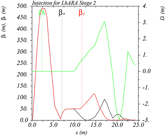
Figure 6. Twiss βx and βy functions and dispersion in the beam line consisting of the modified Stage 1 lattice and the transfer line allowing injection of the beam into the FFA ring. The distance s runs from the laser target to the exit of the injection septum.
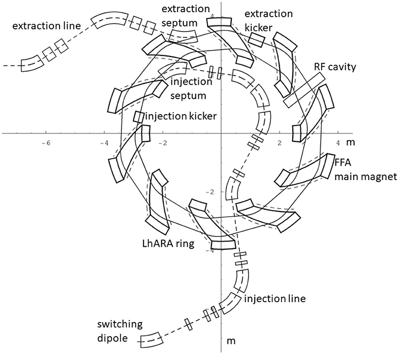
Figure 7. The layout of the injection line from the switching dipole to the injection septum together with the FFA ring, some of its subsystems and the first part of the extraction line.
The magnetic field, By, in the median plane of a scaling spiral FFA is given by [86–88]:
where B0 is the magnetic field at radius R0, k is the field index, ζ corresponds to the spiral angle and F is the “flutter function.” This field law defines a zero-chromaticity condition, which means the working point of the machine is independent of energy (up to field errors and alignment imperfections). This avoids the need to cross any resonances, which would reduce the beam quality and could lead to beam loss.
Table 2 gives the main design parameters of the FFA ring. The ring consists of ten symmetric cells, each containing a single combined-function spiral magnet. The choice of the number of cells is a compromise between the size of the orbit excursion, which dictates the radial extent of the magnet, and the length of the straight sections required to accommodate the injection and extraction systems.
The betatron functions and dispersion in one lattice cell at injection are shown in Figure 8A. The tune diagram, showing the position of the working point of the machine in relation to the main resonance lines, is shown in Figure 8B. Tracking studies were performed using a step-wise tracking code in which the magnetic field is integrated using a Runge-Kutta algorithm [90]. The magnetic field in the median plane was obtained using the ideal scaling law (Equation 3). Enge functions were used to give the fringe fields. The field out of the median plane was obtained using Maxwell's equations and a 6th-order Taylor expansion of the field. The dynamic acceptance for 100 turns, shown for the horizontal and vertical planes in Figures 8C,D, respectively, is significantly larger than the beam emittance. This statement holds even for the pessimistic scenario in which the emittance is assumed to be ten times larger than nominal. These results confirm that a good machine working point has been chosen.
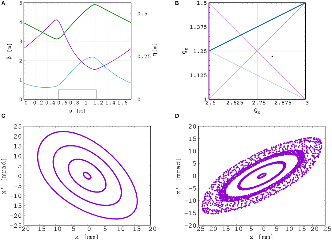
Figure 8. Beam optics and tracking in the FFA. Twiss βh (blue), βv (purple) functions, and dispersion (green) in one lattice cell of the FFA ring (A). The working point of the FFA ring at (2.83, 1.22) on the tune diagram (B). The results of the horizontal (C) and vertical (D) dynamical acceptance study in the FFA ring, where a 1 mm offset is assumed in the vertical and horizontal planes, respectively.
A full aperture, fast injection of the beam will be performed using a magnetic septum, installed on the inside of the ring, followed by a kicker magnet situated in a consecutive lattice cell, as shown in Figure 7. The specifications of the injection system are dictated by the parameters of the beam at injection, which are summarized for the nominal proton beam in Table 3. The beam at injection has a relatively small emittance and short bunch length, which limits the intensity accepted by the ring due to the space-charge effect. An intensity of ~ 109 protons will be accepted by the ring assuming the nominal beam parameters. Space-charge effects will be severe immediately after injection, but will quickly be reduced due to the debunching of the beam. Fast extraction of the beam over the full aperture will be performed using a kicker magnet followed by a magnetic septum installed in a consecutive lattice cell close to the extraction orbit.
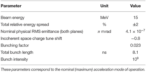
Table 3. Summary of the main parameters for the proton beam at the injection to the FFA ring.
Acceleration of the beam to 127 MeV will be done using an RF system operating at harmonic number h = 1 with an RF frequency range from 2.89 to 6.48 MHz. The RF voltage required for 10 Hz operation is 0.5 kV. However, at this relatively low voltage the energy acceptance at injection is ±0.7%. Operating with a voltage of 4 kV increases the energy acceptance to ±2%. This voltage can be achieved with one cavity [91]. Here, two cavities are proposed to provide greater operational stability. Normal conducting spiral-scaling FFA magnets, similar to the ones needed for LhARA, have been successfully constructed [89, 92] using either distributed, individually-powered coils on a flat pole piece or using a conventional gap-shaping technique. For the LhARA FFA, we propose a variation of the coil-dominated design recently proposed at the Rutherford Appleton Laboratory in R&D studies for the upgrade of the ISIS neutron and muon source. In this case, the nominal scaling field is achieved using a distribution of single-powered windings on a flat pole piece. The parameter k can then be tuned using up to three additional independently-powered windings. The extent of the fringe field across the radius of the magnet must be carefully controlled using a “field clamp” to achieve zero chromaticity. An active clamp, in which additional windings are placed around one end of the magnet, may be used to control the flutter function and thereby vary independently the vertical tune of the FFA ring. The FFA is required to deliver beams over a range of energy; each energy requiring a particular setting for the ring magnets. Therefore, a laminated magnet design may be required to reduce the time needed to change the field. The magnet gap of 4.7 cm given in Table 2 is estimated assuming a flat-pole design for the magnet.
Substantial margins in the beam parameters were assumed in the design of the extraction line from the FFA due to uncertainties in the beam distributions originating from the Stage 1 beam transport, the FFA injection line, and potential distortions introduced by the presence of space-charge effects during acceleration in the ring. The beam emittance was therefore allowed to be as large as a factor of 10 greater than the nominal value, which was derived by assuming that the normalized emittance is conserved from the source, through the Stage 1 beam line, and in the FFA ring. In the nominal case, the physical emittance of the beam is affected by adiabatic damping only. Substantial flexibility in the optics of the extraction line is required, as the extraction line must accommodate a wide spectrum of beam conditions to serve the in vitro and in vivo end-stations.
Detailed studies were carried out for proton beams with kinetic energies of 40 and 127 MeV. Table 4 gives the Twiss β values for different beam sizes for the 40 and 127 MeV proton-beam energies assuming a Gaussian beam distribution. The optics and geometric acceptance of the system is approximately the same for the 40 and 127 MeV beams, justifying the working hypothesis that beam emittance is approximately the same for both beam energies. This assumption will be revised as soon as space-charge simulations for the entire system are available.
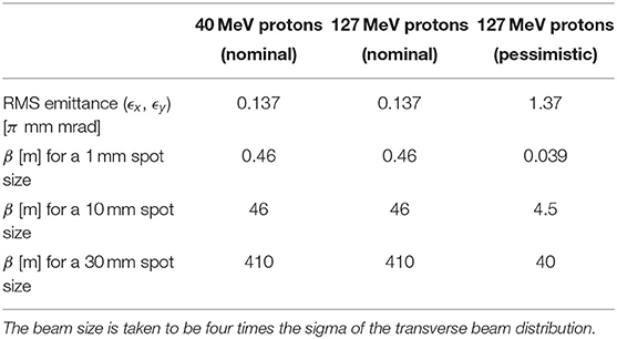
Table 4. Beam emittance values and target β values for different beam sizes for 40 and 127 MeV beams.
The first two dipoles and four quadrupoles of the extraction line bend the beam coming from the extraction septum of the FFA such that it is parallel to the low-energy beam line while ensuring that dispersion is closed. Closing the dispersion is critical, as off-momentum particles will follow trajectories different to those followed by particles with the design momentum and therefore impact the size and shape of the beam downstream. The second part of the extraction line consists of four quadrupoles which transport the beam either to the first dipole of the vertical arc that serves the high-energy in vitro end station or to the in vivo end station if this dipole is not energized. These quadrupoles provide the flexibility required to produce the different beam sizes for the in vitro end station, as specified in Table 4.
The high-energy in vitro beam line transports the beam from the extraction line to the high-energy in vitro end station. The 90° vertical bend is a scaled version of the low-energy vertical arc, following the same design principles, and also consists of two bending dipole magnets and six quadrupole magnets. To accommodate the higher beam energies, the lengths of the magnets were scaled in order to ensure that peak magnetic fields were below the saturation limits of normal conducting magnets. The bending dipole magnet lengths were increased to 1.2 m each and the quadrupole lengths were tripled to 0.3 m. The overall length of the arc then becomes 6 m, compared to 4.6 m for the low energy in vitro arc. This difference in arc length means the high-energy in vitro arc finishes about 0.9 m higher than the low-energy one. This difference can easily be accommodated by adjusting the final drift lengths.
The quadrupole strengths for the scaled high-energy in vitro arc were obtained using MADX calculations, tracking simulations using BDSIM show good agreement with these (see Figure 9). The input beam distribution used in BDSIM was assumed to be Gaussian with Twiss β = 46, which gives a beam size of about 10 mm. Small deviations from the BDSIM results were observed in GPT simulations due to space-charge effects.
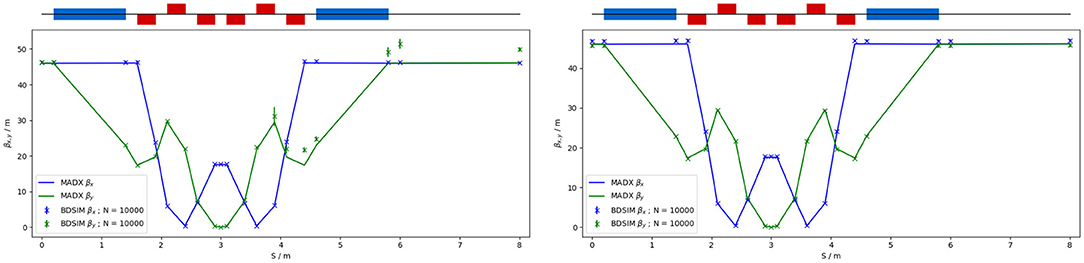
Figure 9. Comparison of MADX and BDSIM simulation of 40 MeV (left) and a nominal 127 MeV (right) proton beam passing through the high energy in vitro arc simulated with 104 particles (in BDSIM).
To facilitate efficient small-animal handling, the end station dedicated to in vivo experiments will be positioned adjacent to the principle road access to the facility. If the first dipole of the high-energy in vitro arc is not energized, the beam is sent to the in vivo end station. From the end of the extraction line, 7.7 m of drift is necessary to clear the first bending dipole of the in vitro arc, to provide space for the five RF cavities needed for longitudinal phase-space manipulation and to allow space for diagnostic devices. Following this drift is a further 6.6 m of beam line that includes four quadrupoles, each of length 0.4 m, which are used to perform the final focusing adjustments of the beam delivered to the in vivo end station. A final 1.5 m drift length is reserved for scanning magnets so spot scanning can be performed and to allow for penetration of the shielding of the in vivo end station. In total, the in vivo beam line is 15.6 m in length.
The flexible design can match the various βx,y values given in Table 4, but not the smallest target value of βx,y = 0.039 m for the pessimistic scenario, which is very challenging. To verify that the optics design can provide the required beam sizes, simulations were performed with BDSIM using an input Gaussian beam generated with the Twiss β values given in Table 4. Figure 10 shows the results for a 40 MeV proton beam and a nominal emittance 127 MeV proton beam matched in order to obtain beam sizes of 1, 10, and 30 mm.
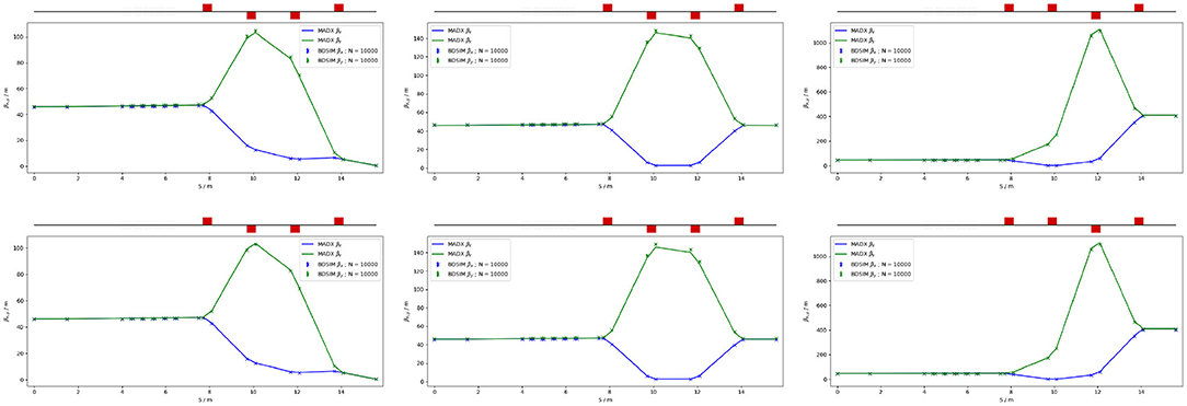
Figure 10. MADX and BDSIM simulations of the in vivo beam line for a 40 MeV proton beam (top row) and a nominal 127 MeV proton beam (bottom row) with quadrupoles matched to obtain βx,y = 0.46 m (left), βx,y = 46 m (middle), and βx,y = 410 m (right) at the end of the beam line for 104 particles.
Commercial off-the-shelf (COTS) instrumentation will be used for Stages 1 and 2 of LhARA wherever possible. However, the characteristics of the beam (e.g., very high charge-per-bunch, low-to-moderate energy) will require that some custom solutions be developed. The authors are developing two concepts, termed SciWire and SmartPhantom, for the low- and high-energy in vitro end stations, respectively. These detectors can also be used for beam diagnostics and may find application at other facilities. Instrumentation for the detection of secondary particles arising from the interaction of the beam with tissue is not discussed here but is an important area that will be studied in the future.
For the Stage 1 beam, the maximum proton energy is 15 MeV. Shot-to-shot characterization of the beam is essential and requires the use of a very thin detector with a fast response. The SciWire [93] is being developed to provide energy and intensity profile measurements for low-energy ion beams. A single SciWire plane consists of two layers of 250 μm square-section scintillating fibers, with the fiber directions in the two layers orthogonal to each other. A series of back-to-back planes provides a homogeneous volume of scintillator. If there are enough planes to stop the beam, the depth of penetration will allow the beam energy to be inferred. This is a destructive measurement so would only be performed when experiments are not running. A single plane, however, can be used for 2D beam-profile measurements while the beam is being delivered for experiments. Light from the SciWire fibers may be detected using a CMOS camera or photodiodes. If the instrumentation is sufficiently fast, the SciWire can be used to derive feedback signals for beam tuning.
To study the dose profile of Stage 2 beams in real time, the SmartPhantom [94] is being developed. This is a water-filled phantom, instrumented with planes of scintillating fibers, used to infer the dose distribution with distance. The detection elements of the SmartPhantom are 250 μm diameter, round scintillating fibers. Each fiber station consists of two planes of fibers, in which the fiber directions are orthogonal. Five fiber stations are arranged in the phantom in front of the cell-culture flask. The fibers may be coupled to photodiodes, or a CMOS camera. Simulations in GEANT4 are being used to develop analysis techniques to determine the position of the Bragg peak shot-by-shot. The beam profile and dose delivered can then be calculated in real time.
The requirement for instrumentation begins with the Ti:Sapphire laser. The laser focal spot will be characterized using a camera-based system and high-speed wavefront measurements [95] from COTS vendors.
For the Stage 1 beam line, beam position monitors (BPMs) will be needed for beam steering. Because of the low beam energy, non-intercepting BPMs using capacitive pickup buttons will be used. Custom pickups will be needed to match the beam pipe geometry, but COTS electronics are available. The beam current will be monitored near the end of each beam line, using integrating current toroids (ICT), backed up with the option of insertable multi-layer Faraday cups (MLFC) to give absolute beam current and energy measurements. Beam profiles could be measured by secondary emission monitor (SEM) grids on both Stage 1 and Stage 2 beam lines. For Stage 1, these monitors will be mounted on pneumatic actuators to avoid scattering. Each end station could be equipped with insertable “pepper-pot” emittance monitors and a transverse deflection cavity with fluorescent screen could be provided for bunch shape measurements.
The BPMs on the FFA will require pickup designs suitable for the unusual, wide and shallow vacuum vessel. The FFA at the KURNS facility in Kyoto has a similar layout [96] and uses a kicker and capacitive pickup to perform tune measurements in each transverse direction. A minimum of one BPM every second cell will be used in the FFA so that the beam orbit can be measured. BPMs will also be required close to the injection and extraction septa. The BPM system may be able to use COTS electronics, but the pickups will be based on the KURNS design of multiple electrodes arranged across the vacuum vessel width.
The data acquisition system needs to be able to store calibration data and apply corrections in real time. It is necessary to be able to find the beam center from a profile, even when the profile may be non-Gaussian and possibly asymmetric. Field programmable gate arrays (FPGAs) can be used to perform fast fitting and pattern recognition of beam profiles. The instrumentation will be integrated with the accelerator control system and will provide fast feedback and adjustment of the beam parameters in real time.
In order to deliver a successful radiobiological research programme, high-end and fully equipped in vitro and in vivo end-stations will be housed within the LhARA facility. The two in vitro end-stations (high and low energy) will contain vertically-delivered beam lines which will be used for the irradiation of 2D monolayer and 3D-cell systems (spheroids and patient-derived organoids) in culture. The beam line within the end-stations will be housed in sealed units that will be directly sourced with appropriate gases (carbon dioxide and nitrogen), allowing the cells within culture plates to be incubated for a short time in stable conditions prior to and during irradiation. This will also enable the chamber to act, where necessary, as a hypoxia unit (e.g. 0.1–5% oxygen concentration). Furthermore, these sealed units will contain robotics to enable the numerous cell culture plates housed within to be placed into and taken out of the beam.
The in vitro end-stations will be located within a research laboratory equipped with state-of-the-art facilities. The laboratory will include all the necessary equipment for bench-top science, sample processing and analysis (e.g., refrigerated centrifuges and light/fluorescent microscopes), along with the equipment required for contaminant-free cell culture (e.g., humidified CO2 cell culture incubators, Class II biological safety cabinets), and for the storage of biological samples and specimens (e.g., −20 and −80°C freezers and fridges). The laboratory will also house an X-ray irradiator (allowing direct RBE comparisons between conventional photon irradiation, and the proton and carbon ions delivered by the accelerator), a hypoxia chamber (for long-term hypoxia studies), a robotic workstation (for handling and processing of large sample numbers, aiding high-throughput screening experiments), and an ultra-pure-water delivery system. These facilities will enable a myriad of biological end-points to be investigated in both normal- and tumor-cell models not only from routine clonogenic survival and growth assays, but also from significantly more complex end-points (e.g., inflammation, angiogenesis, senescence, and autophagy).
The in vivo end-station will be served with relatively high-energy proton and carbon ions capable of penetrating deeper into tissues allowing the irradiation of whole animals. The ability to perform in vivo pre-clinical studies is vital for the future effective translation of the research into human cancer patients where optimum treatment strategies and the reduction of side-effects are crucial. The in vivo end-station will allow the irradiation of a number of small-animal models (e.g., xenograft mouse and rat models) which can further promote an examination of particular ions on the appropriate biological end-points (e.g., tumor growth and normal tissue responses). The end-station will contain a small-animal handling area which will allow for the anaesthetization of animals prior to irradiation. To enable the irradiation of small target volumes with a high level of precision and accuracy, an image guidance system (e.g., computed tomography) will be available. The animals will subsequently be placed in temperature-controlled holder tubes enabling the correct positioning of the relevant irradiation area in front of the beam line. The beam size is sufficient to give flexibility in the different irradiation conditions, in particular through passive scattering, pencil-beam scanning, and micro-beam irradiation, to be investigated at both conventional and FLASH dose rates. It is envisaged that the animals will be taken off-site post-irradiation to a nearby animal-holding facility for a follow-up period where biological measurements will be conducted.
The LhARA facility will encompass two floors of roughly 42 m in length and 18 m in width. The ground floor will contain the laser, accelerator, and in vivo end station while the first floor will house the laboratory area and the two in vitro end stations. The entire facility will require radiation protection in the form of concrete shielding. There will be three principal areas: a radiation controlled-access area, a laser controlled-access area, and a laboratory limited-access area.
For a facility such as LhARA, laser, radiation and biological safety are primary concerns. It is envisaged that LhARA will be built at a national laboratory or equivalent research institute which has an established safety-management system and culture in place.
The infrastructure and integration of the LhARA facility will require R&D in four key areas: risk analysis (project risks), risk assessments (safety risks), radiation simulations, and controls development. The risk analysis will cover all aspects of the facility, such as funding and resource availability, not just technical risks. A safety-risk assessment will be performed to describe and control all potential safety risks in the facility. The safety-risk assessment will, to a reasonable degree, identify all pieces of equipment that require safety mitigations and identify control measures that must be put in place. Coupled closely with the safety-risk assessment, radiation simulations will be developed to characterize the radiation hazards in and around the LhARA facility. The last area to require R&D will be the control systems. It is expected that the facility will use the Experimental Physics and Industrial Control System [97], which can be further developed at this stage.
The dose distributions delivered to the end stations were evaluated using BDSIM. Figure 11 shows the energy lost by the beam as it enters the low-energy in vitro end station. The beam passes through the vacuum window, a layer of scintillating fiber, and a 5 mm air gap. The beam then enters the cell-sample container, assumed to be polystyrene, which supports a 30 μm thick layer of cells, modeled using the GEANT4 material “G4_SKIN_ICRP” [98]. The transverse momentum of protons in the beam was assumed to follow a Gaussian distribution, with a lateral spread small enough for the beam to be fully contained within the required spot size of 3 cm. Figure 11 shows that a proton beam with 10 MeV kinetic energy does not reach the cell layer. The Bragg peak of a 12 MeV proton beam is located close to the cell layer, while a 15 MeV beam, the maximum energy specified for delivery to the low-energy in vitro end station, has a Bragg peak located beyond the cell layer. LhARA's ability to deliver various beam energies will allow the investigation of the radiobiological effects of irradiation using different parts of the Bragg peak, effectively varying the LET across the sample. RF cavities are placed in both the stage 1 and the stage 2 beam lines to allow the manipulation of the energy of the bunch as a function of time. This facility will allow the study of the impact of a “spread-out Bragg peak” (SOBP).
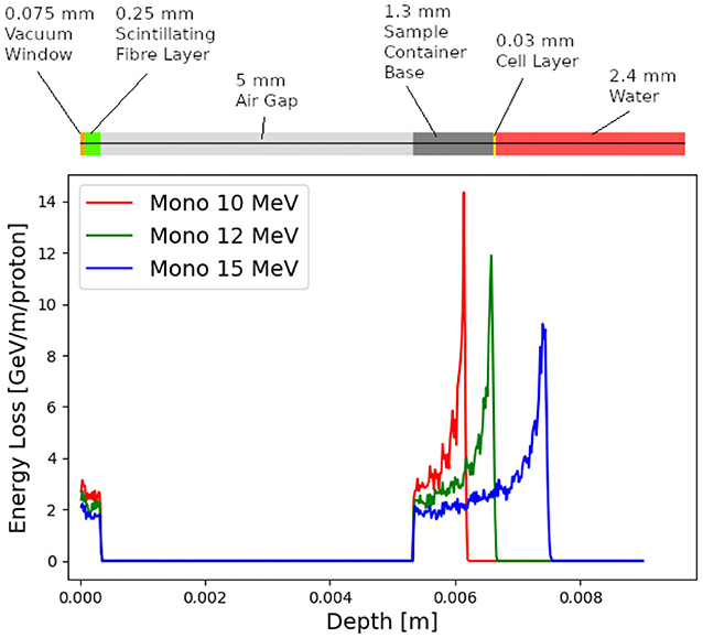
Figure 11. Energy loss as a function of depth in the low-energy in vitro end station for three mono-energetic proton energies: 10, 12, and 15 MeV. Each beam was simulated using 104 particles at the start of the end station. The material through which the beam passes is indicated above the figure. The vacuum window is plotted at a depth value of 0 m. The beam deposits energy in the vacuum window and the layer of scintillating fiber before passing through an air gap and entering the sample container.
The maximum dose that can be delivered was evaluated for a variety of beam energies. In order for the dose to be reported in units of Gray it is necessary to define the volume within which the energy deposition is to be integrated. Therefore, the dose was estimated from simulations by calculating the energy deposited in a volume of water corresponding in size to the sensitive volume of a PTW 23343 Markus ion chamber [99] placed at the position of the Bragg peak in each case. This choice allows the doses and dose-rates reported here to be compared to those of operating facilities. The cylindrical sensitive volume of the ion chamber has a radius of 2.65 mm and a depth of 2 mm, giving a volume of about 4.4 × 10⁻⁸ m3. The total energy deposited within the chamber was recorded and converted into dose in units of Gray.
For the low-energy in vitro end station, the minimum spot size has a diameter of 10 mm, which is larger than the area of the chamber. A single shot of 109 protons at 12 MeV with this spot size deposits 3.1 × 10⁻⁴ J in the chamber volume, corresponding to a dose of 7.1 Gy. For this simulation, the thickness of the sample container was reduced so that the Bragg peak could be positioned within the chamber volume. For the bunch length of 7.0 ns, the maximum instantaneous dose rate is 1.0 × 10⁹ Gy/s and the average dose rate is 71 Gy/s, assuming a repetition rate of 10 Hz. A single shot of 109 protons at 15 MeV deposits 5.6 × 10⁻⁴ J in the chamber volume, corresponding to a dose of 12.8 Gy. This gives an instantaneous dose rate of 1.8 × 10⁹ Gy/s and an average dose rate of 128 Gy/s assuming the same bunch length and repetition rate as for the 12 MeV case.
For the high-energy in vitro end station, a similar design to the low-energy end station was used, but the air gap was increased from 5 mm to 5 cm and a water phantom was placed at the end of the air gap instead of a cell culture plate. The water phantom used in the simulation was based upon the PTC T41023 water phantom [100]. In addition, the smaller minimum design beam size of 1 mm was used. A single shot of 109 protons at 127 MeV deposits 6.9 × 10⁻⁴ J in the chamber at the pristine Bragg peak depth, corresponding to a dose of 15.6 Gy, an instantaneous dose rate of 3.8 × 10⁸ Gy/s and an average dose rate of 156 Gy/s. The end-station design assumed for a 33.4 MeV/u carbon beam was the same as that used for the low-energy in vitro end station due to the limited range in water of the carbon beam. The intensity of the beam is assumed to be a factor of 12 less than that for protons in order to preserve the same strength of the space-charge effect at injection into the FFA with the same beam parameters because the incoherent space charge tune shift is proportional to q2/A and inversely proportional to β2γ3, where q is the particle charge, A its mass number, and β and γ its relativistic parameters. A single pulse of 8.3 × 10⁷ ions deposits 3.2 × 10⁻³ J at the depth of the pristine Bragg peak, leading to an instantaneous dose rate of 9.7 × 10⁸ Gy/s and a maximum average dose rate of 730 Gy/s.
The expected maximum dose rates are summarized in Table 5. The instantaneous dose rates depend on the bunch length which differs depending on the energies. For the low-energy in vitro line, a 7 ns bunch length is assumed for all energies. For the higher energies, a 127 MeV proton beam is delivered with a bunch length of 41.5 ns, and a bunch length of 75.2 ns for a 33.4 MeV/u carbon beam. The same repetition rate of 10 Hz was used for all energies. The minimum beam size at the start of the end station for the 12 and 15 MeV proton-beam simulations was 1 cm. A 1 mm beam size was used for the 127 MeV proton beam and 33.4 MeV/u carbon-ion beam simulations.
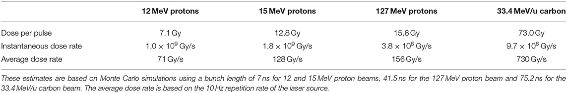
Table 5. Summary of expected maximum dose per pulse and dose rates that LhARA can deliver for minimum beam sizes.
The initial conceptual design of LhARA, the Laser-hybrid Accelerator for Radiobiological Applications, has been described and its performance evaluated in simulations that take into account the key features of the facility. LhARA uses a laser-driven source to create a large flux of protons or light ions which are captured and formed into a beam by strong-focusing plasma lenses, thus evading prevalent space-charge limits on the instantaneous dose rate that can be delivered. Acceleration, performed using a fixed-field alternating-gradient accelerator, preserves the unique flexibility in the time, spectral, and spatial structure of the beam afforded by the laser-driven source. The ability to trigger the laser pulse that initiates the production of protons or ions at LhARA will allow the time structure of the beam to be varied to interrupt the chemical and biological pathways that determine the biological response to ionizing radiation. The almost parallel beam that LhARA will deliver can be varied to illuminate a circular area with a maximum diameter of between 1 and 3 cm with an almost uniform dose, or focused to a spot with diameter of ~ 1 mm. These features will allow radiobiological studies to be carried out in completely new regimens, delivering a variety of ion species in a broad range of time structures and spatial configurations at instantaneous dose rates up to and potentially significantly beyond the current ultra-high dose-rate “FLASH” regime.
The enhanced understanding these studies will provide, may in turn result in new approaches to radiotherapy, decreasing the radio-toxicity for normal tissue while maintaining or enhancing the tumor-control probability. Further, by developing a triggerable system that incorporates dose-deposition imaging in a fast feedback-and-control system, in the long term LhARA has the potential to remove the requirement for a large gantry for proton and ion therapy, laying the foundations for “best in class” treatments to be made available to the many by reducing the footprint of future particle-beam therapy systems.
The radiobiology programme in combination with the demonstration in operation of the laser-hybrid technique means that the LhARA programme has the potential to drive a step-change in the clinical practice of proton- and ion-beam therapy.
The raw data supporting the conclusions of this article will be made available by the authors without undue reservation.
GA: integration engineering. TB: led Maxeler contributions. SB: led JAI team at RHUL. MB: laser-acceleration. RB: plasma-dynamics calculations. CB: led the STFC Central Laser Facility contributions. PB: led the JAI Oxford contributions. OE: particle distributions at the target. TD: beam dynamics calculations. SGi: simulation of the particle transport. TG: University of Liverpool lead author. SGr: ion-beam radiobiology. DG: advised on clinical applications. CH: led the medical-physics team at Charing Cross Hospital. JH: in-vitro and in-vivo end-station design. WJ: provided the Lay Summary. KK: advised on the end-stations. AK: project manager. J-BL: FFA design. KL: project leader. WL: real-time and offline processing. JM: led specification of instrumentation. PM: led Stratchclyde contributions. RM: advised on imaging and instrumentation. ZN: led the laser-driven source team. HL: transfer-line design. JLP: led the radiobiology work package. JPa: led the accelerator-system design. JPo: provided the initial concept. KP: advised on the radiobiology programme. MP: contributed to the end-station diagnostics. PR: led the Cockcroft Institute's contributions. GS: advised on dosimetry. WS: simulated LhARA Stage 1. SS: led the Daresbury Laboratory contributions. JT: led the ISIS engineering effort. ST: advised on technology development. PW: novel diagnostic-systems. CW: plasma-lens project lead. RX: advised on the data-handling aspects. All authors contributed to the article and approved the submitted version.
The work described here was made possible by a grant from the Science and Technology Facilities Council (ST/T002638/1, ST/P002021/1). Additional support was provided by the STFC Rutherford Appleton and Daresbury Laboratories and members of the LhARA consortium.
TB was employed by Maxeler Technologies and RX was employed by the company Corerain Technologies.
The remaining authors declare that the research was conducted in the absence of any commercial or financial relationships that could be construed as a potential conflict of interest.
We gratefully acknowledge all sources of support. A pre-publication review of the pre-CDR for LhARA was carried out by P. Bolton (LMU, Munich), M. Lamont (CERN), Y. Prezado (Institut Curie), and F. Romano (INFN-LNS and the National Physical Laboratory). We were grateful to the review panel for their support and detailed feedback on the draft pre-CDR.
1. The World Health Organisation. Cancer (2020). Available online at: https://www.who.int/news-room/fact-sheets/detail/cancer
2. Bray F, Ferlay J, Soerjomataram I, Siegel RL, Torre LA, Jemal A. Global cancer statistics 2018: GLOBOCAN estimates of incidence and mortality worldwide for 36 cancers in 185 countries. CA Cancer J Clin. (2018) 68:394–424. doi: 10.3322/caac.21492
3. Fitzmaurice C, Akinyemiju TF, Al Lami FH, Alam T, Alizadeh-Navaei R, Allen C, et al. Global, regional, and national cancer incidence, mortality, years of life lost, years lived with disability, and disability-adjusted life-years for 29 cancer groups, 1990 to 2016. JAMA Oncol. (2018) 4:1553. doi: 10.1200/JCO.2018.36.15_suppl.1568
4. Atun R, Jaffray DA, Barton MB, Bray F, Baumann M, Vikram B, et al. Expanding global access to radiotherapy. Lancet Oncol. (2015) 16:1153–86. doi: 10.1016/S1470-2045(15)00222-3
5. Datta NR, Rogers S, Bodis S. Challenges and opportunities to realize “The 2030 Agenda for Sustainable Development” by the United Nations: implications for radiation therapy infrastructure in low- and middle-income countries. Int J Radiat Oncol Biol Phys. (2019) 105:918–33. doi: 10.1016/j.ijrobp.2019.04.033
6. Berry RJ. Effects of radiation dose-rate: from protracted, continuous irradiation to ultra-high dose-rates from pulsed accelerators. Br Med Bull. (1973) 29:44–7. doi: 10.1093/oxfordjournals.bmb.a070955
7. Favaudon V, Caplier L, Monceau V, Pouzoulet F, Sayarath M, Fouillade C, et al. Ultrahigh dose-rate FLASH irradiation increases the differential response between normal and tumor tissue in mice. Sci Transl Med. (2014) 6:245ra93. doi: 10.1126/scitranslmed.3008973
8. Durante M, Bräuer-Krisch E, Hill M. Faster and safer? FLASH ultra-high dose rate in radiotherapy. Br J Radiol. (2018) 91:20170628. doi: 10.1259/bjr.20170628
9. Vozenin MC, Hendry JH, Limoli CL. Biological benefits of ultra-high dose rate FLASH radiotherapy: sleeping beauty awoken. Clin Oncol. (2019) 31:407–15. doi: 10.1016/j.clon.2019.04.001
10. Wilson JD, Hammond EM, Higgins GS, Petersson K. Ultra-high dose rate (FLASH) radiotherapy: silver bullet or fool's gold? Front Oncol. (2020) 9:1563. doi: 10.3389/fonc.2019.01563
11. Prezado Y, Fois G. Proton-minibeam radiation therapy: a proof of concept. Med Phys. (2013) 40:031712. doi: 10.1118/1.4791648
12. Prezado Y, Jouvion G, Hardy D, Patriarca A, Nauraye C, Bergs J, et al. Proton minibeam radiation therapy spares normal rat brain: long-term clinical, radiological and histopathological analysis. Sci Rep. (2017) 7:14403. doi: 10.1038/s41598-017-14786-y
13. Prezado Y, Dos Santos M, Gonzalez W, Jouvion G, Guardiola C, Heinrich S, et al. Transfer of minibeam radiation therapy into a cost-effective equipment for radiobiological studies: a proof of concept. Sci Rep. (2017) 7:17295. doi: 10.1038/s41598-017-17543-3
14. Prezado Y, Jouvion G, Patriarca A, Nauraye C, Guardiola C, Juchaux M, et al. Proton minibeam radiation therapy widens the therapeutic index for high-grade gliomas. Sci Rep. (2018) 8:16479. doi: 10.1038/s41598-018-34796-8
15. González W, Prezado Y. Spatial fractionation of the dose in heavy ions therapy: an optimization study. Med Phys. (2018) 45:2620–7. doi: 10.1002/mp.12902
16. Martínez-Rovira I, González W, Brons S, Prezado Y. Carbon and oxygen minibeam radiation therapy: an experimental dosimetric evaluation. Med Phys. (2017) 44:4223–9. doi: 10.1002/mp.12383
17. The LhARA Consortium. The Laser-hybrid Accelerator for Radiobiological Applications. CCAP-TN-01 (2020). Available online at: https://ccap.hep.ph.ic.ac.uk/trac/raw-attachment/wiki/Communication/Notes/CCAP-TN-01.pdf
18. Loeffler JS, Durante M. Charged particle therapy—optimization, challenges and future directions. Nat Rev Clin Oncol. (2013) 10:411–24. doi: 10.1038/nrclinonc.2013.79
20. Paganetti H, van Luijk P. Biological considerations when comparing proton therapy with photon therapy. Semin Radiat Oncol. Philadelphia, PA: W. B. Saunders (2013) 23:77–87. doi: 10.1016/j.semradonc.2012.11.002
21. Paganetti H. Relative biological effectiveness (RBE) values for proton beam therapy. Variations as a function of biological endpoint, dose, and linear energy transfer. Phys Med Biol. (2014) 59:R419. doi: 10.1088/0031-9155/59/22/R419
22. Chaudhary P, Marshall TI, Perozziello FM, Manti L, Currell FJ, Hanton F, et al. Relative biological effectiveness variation along monoenergetic and modulated Bragg peaks of a 62-MeV therapeutic proton beam: a preclinical assessment. Int J Radiat Oncol Biol Phys. (2014) 90:27–35. doi: 10.1016/j.ijrobp.2014.05.010
23. Wilkens JJ, Oelfke U. A phenomenological model for the relative biological effectiveness in therapeutic proton beams. Phys Med Biol. (2004) 49:2811–25. doi: 10.1088/0031-9155/49/13/004
24. Karger CP, Peschke P. RBE and related modeling in carbon-ion therapy. Phys Med Biol. (2017) 63:01TR02. doi: 10.1088/1361-6560/aa9102
25. Vitti ET, Parsons JL. The radiobiological effects of proton beam therapy: impact on DNA damage and repair. Cancers. (2019) 11:946. doi: 10.3390/cancers11070946
26. Carter RJ, Nickson CM, Thompson JM, Kacperek A, Hill MA, Parsons JL. Complex DNA damage induced by high linear energy transfer alpha-particles and protons triggers a specific cellular DNA damage response. Int J Radiat Oncol Biol Phys. (2018) 100:776–84. doi: 10.1016/j.ijrobp.2017.11.012
27. Wilson J, Hammond EM, Higgins GS, Petersson K. Corrigendum: ultra-high dose rate (FLASH) radiotherapy: silver bullet or fool's gold? Front Oncol. (2020) 10:210. doi: 10.3389/fonc.2020.00210
28. Bourhis J, Sozzi WJ, Jorge PG, Gaide O, Bailat C, Duclos F, et al. Treatment of a first patient with FLASH-radiotherapy. Radiother Oncol. (2019) 139:18–22. doi: 10.1016/j.radonc.2019.06.019
29. Bulanov SV, Esirkepov TZ, Khoroshkov VS, Kuznetsov AV, Pegoraro F. Oncological hadrontherapy with laser ion accelerators. Phys Lett A. (2002) 299:240–7. doi: 10.1016/S0375-9601(02)00521-2
30. Fourkal E, Li JS, Ding M, Tajima T, Ma CM. Particle selection for laser-accelerated proton therapy feasibility study. Med Phys. (2003) 30:1660–70. doi: 10.1118/1.1586268
31. Malka V, Fritzler S, Lefebvre E, d'Humières E, Ferrand R, Grillon G, et al. Practicability of proton therapy using compact laser systems. Med Phys. (2004) 31:1587–92. doi: 10.1118/1.1747751
32. Ledingham KWD, McKenna P, Singhal RP. Applications for nuclear phenomena generated by ultra-intense lasers. Science. (2003) 300:1107–111.
33. Kraft SD, Richter C, Zeil K, Baumann M, Beyreuther E, Bock S, et al. Dose-dependent biological damage of tumour cells by laser-accelerated proton beams. New J Phys. (2010) 12:85003. doi: 10.1088/1367-2630/12/8/085003
34. Fiorini F, Kirby D, Borghesi M, Doria D, Jeynes JC, Kakolee KF, et al. Dosimetry and spectral analysis of a radiobiological experiment using laser-driven proton beams. Phys Med Biol. (2011) 56:6969–82. doi: 10.1088/0031-9155/56/21/013
35. Yogo A, Maeda T, Hori T, Sakaki H, Ogura K, Nishiuchi M, et al. Measurement of relative biological effectiveness of protons in human cancer cells using a laser-driven quasimonoenergetic proton beamline. Appl Phys Lett. (2011) 98:053701. doi: 10.1063/1.3551623
36. Bin J, Allinger K, Assmann W, Dollinger G, Drexler GA, Friedl AA, et al. A laser-driven nanosecond proton source for radiobiological studies. Appl Phys Lett. (2012) 101:243701. doi: 10.1063/1.4769372
37. Doria D, Kakolee KF, Kar S, Litt SK, Fiorini F, Ahmed H, et al. Biological effectiveness on live cells of laser driven protons at dose rates exceeding 109 Gy/s. AIP Adv. (2012) 2:011209. doi: 10.1063/1.3699063
38. Zeil K, Baumann M, Beyreuther E, Burris-Mog T, Cowan TE, Enghardt W, et al. Dose-controlled irradiation of cancer cells with laser-accelerated proton pulses. Appl Phys B. (2013) 110:437–44. doi: 10.1007/s00340-012-5275-3
39. Masood U, Bussmann M, Cowan TE, Enghardt W, Karsch L, Kroll F, et al. A compact solution for ion beam therapy with laser accelerated protons. Appl Phys B. (2014) 117:41–52. doi: 10.1007/s00340-014-5796-z
40. Zlobinskaya O, Siebenwirth C, Greubel C, Hable V, Hertenberger R, Humble N, et al. The effects of ultra-high dose rate proton irradiation on growth delay in the treatment of human tumor xenografts in nude mice. Radiat Res. (2014) 181:177–83. doi: 10.1667/RR13464.1
41. Pommarel L, Vauzour B, Mégnin-Chanet F, Bayart E, Delmas O, Goudjil F, et al. Spectral and spatial shaping of a laser-produced ion beam for radiation-biology experiments. Phys Rev Acceler Beams. (2017) 20:1–10. doi: 10.1103/PhysRevAccelBeams.20.032801
42. Manti L, Perozziello FM, Borghesi M, Candiano G, Chaudhary P, Cirrone GAP, et al. The radiobiology of laser-driven particle beams: focus on sub-lethal responses of normal human cells. J Instrum. (2017) 12:C03084. doi: 10.1088/1748-0221/12/03/C03084
43. A-SAIL Project. A-SAIL Project. (2020). Available online at: https://www.qub.ac.uk/research-centres/A-SAILProject/
44. Cirrone GAP, Margarone D, Maggiore M, Anzalone A, Borghesi M, Jia SB, et al. ELIMED: a new hadron therapy concept based on laser driven ion beams. In: Esarey E, Schroeder CB, Leemans WP, Ledingham KWD, Jaroszynski DA, editors. Laser Acceleration of Electrons, Protons, and Ions II; and Medical Applications of Laser-Generated Beams of Particles II; and Harnessing Relativistic Plasma Waves III, Vol. 8779. Prague: International Society for Optics and Photonics. SPIE (2013). p. 216–25.
45. Wiggins SM, Boyd M, Brunetti E, Butler NMH, Feehan JS, Gray RJ, et al. Application programmes at the Scottish Centre for the application of plasma-based accelerators (SCAPA). In: Jaroszynski DA, Hur M, editors. Relativistic Plasma Waves and Particle Beams as Coherent and Incoherent Radiation Sources III, Vol. 11036. International Society for Optics and Photonics. SPIE (2019). p. 93–103.
46. Romano F, Schillaci F, Cirrone GAP, Cuttone G, Scuderi V, Allegra L, et al. The ELIMED transport and dosimetry beamline for laser-driven ion beams. Nucl Instr Methods Phys Res A. (2016) 829:153–8. doi: 10.1016/j.nima.2016.01.064
47. Masood U, Cowan TE, Enghardt W, Hofmann KM, Karsch L, Kroll F, et al. A light-weight compact proton gantry design with a novel dose delivery system for broad-energetic laser-accelerated beams. Phys Med Biol. (2017) 62:5531–55. doi: 10.1088/1361-6560/aa7124
48. Chaudhary P, Gwynne D, Doria D, Romagnani L, Maiorino C, Padda H, et al. Effectiveness of laser accelerated ultra high dose rate protons in DNA DSB damage induction under hypoxic conditions. In: 44th EPS Conference on Plasma Physics, EPS 2017, Vol. 44F. Belfast: European Physical Society (EPS) (2017). p. P1.217.
49. Margarone D, Cirrone GAP, Cuttone G, Amico A, Andò L, Borghesi M. ELIMAIA: a laser-driven ion accelerator for multidisciplinary applications. Quant Beam Sci. (2018) 2:8. doi: 10.3390/qubs2020008
50. Cirrone GAP, Catalano R, Cuttone G, Margarone D, Schillaci F, Petringa G. Generation control and application of flash radiation beam from laser-matter interaction: the ELIMAIA-ELIMED beamline. Nuovo Cim C. (2020) 43:15. doi: 10.1393/ncc/i2020-20015-6
51. Schillaci F, Andò L, Cirrone G, Cuttone G, Maggiore M, Margarone D. Advanced beam transport solutions for ELIMAIA: a user oriented laser-driven ion beamlines. In: 10th International Particle Accelerator Conference. Melbourne, VIC (2019). p. TUPTS005.
52. Cirrone G, Allegra L, Amato A, Amico A, Candiano G, Caruso A, et al. Status, plans and potential applications of the ELIMED beam line at ELI-beamlines. In: 7th International Particle Accelerator Conference. Busan (2016). p. WEXB01.
53. Milluzzo G, Scuderi V, Amico AG, Borghesi M, Cirrone GAP, Cuttone G, et al. Laser-accelerated ion beam diagnostics with TOF detectors for the ELIMED beam line. JINST. (2017) 12:C02025. doi: 10.1088/1748-0221/12/02/C02025
54. Pipek J, Romano F, Milluzzo G, Cirrone GAP, Cuttone G, Amico AG, et al. Monte Carlo simulation of the ELIMED beamline using Geant4. JINST. (2017) 12:C03027. doi: 10.1088/1748-0221/12/03/C03027
55. Milluzzo G, Pipek J, Amico AG, Cirrone GAP, Cuttone G, Korn G, et al. Geant4 simulation of the ELIMED transport and dosimetry beam line for high-energy laser-driven ion beam multidisciplinary applications. Nucl Instrum Meth A. (2018) 909:298–302. doi: 10.1016/j.nima.2018.02.066
56. Dover NP, Nishiuchi M, Sakaki H, Kondo K, Lowe HF, Alkhimova MA, et al. Demonstration of repetitive energetic proton generation by ultra-intense laser interaction with a tape target. High Energy Density Phys. (2020) 37:100847. doi: 10.1016/j.hedp.2020.100847
57. Clark EL, Krushelnick K, Davies JR, Zepf M, Tatarakis M, Beg FN, et al. Measurements of energetic proton transport through magnetized plasma from intense laser interactions with solids. Phys Rev Lett. (2000) 84:670–3. doi: 10.1103/PhysRevLett.84.670
58. Snavely RA, Key MH, Hatchett SP, Cowan TE, Roth M, Phillips TW, et al. Intense high-energy proton beams from petawatt-laser irradiation of solids. Phys Rev Lett. (2000) 85:2945–8. doi: 10.1103/PhysRevLett.85.2945
59. Daido H, Nishiuchi M, Pirozhkov AS. Review of laser-driven ion sources and their applications. Rep Prog Phys. (2012) 75:56401. doi: 10.1088/0034-4885/75/5/056401
60. Roth M, Schollmeier M. Ion acceleration-target normal sheath acceleration. CAS-CERN Accelerator School: Plasma Wake Acceleration 2014, Proceedings. (2014) 1, 231–270. doi: 10.5170/CERN-2016-001.231
61. Clark EL, Krushelnick K, Zepf M, Beg FN, Tatarakis M, Machacek A, et al. Energetic heavy-ion and proton generation from ultraintense laser-plasma interactions with solids. Phys Rev Lett. (2000) 85:1654–7. doi: 10.1103/PhysRevLett.85.1654
62. Passoni M, Bertagna L, Zani A. Target normal sheath acceleration: theory, comparison with experiments and future perspectives. New J Phys. (2010) 12:045012. doi: 10.1088/1367-2630/12/4/045012
63. Willingale L, Nagel SR, Thomas AGR, Bellei C, Clarke RJ, Dangor AE, et al. Characterization of high-intensity laser propagation in the relativistic transparent regime through measurements of energetic proton beams. Phys Rev Lett. (2009) 102:125002. doi: 10.1103/1007
64. Bin J, Ma W, Wang H, Streeter M, Kreuzer C, Kiefer D, et al. Ion acceleration using relativistic pulse shaping in near-critical-density plasmas. Phys Rev Lett. (2015) 115:064801. doi: 10.1103/PhysRevLett.115.064801
65. Chen SN, Vranic M, Gangolf T, Boella E, Antici P, Bailly-Grandvaux M, et al. Collimated protons accelerated from an overdense gas jet irradiated by a 1 m wavelength high-intensity short-pulse laser. Sci Rep. (2017) 7:13505. doi: 10.1038/s41598-017-12910-6
66. Margarone D, Velyhan A, Dostal J, Ullschmied J, Perin JP, Chatain D, et al. Proton acceleration driven by a nanosecond laser from a cryogenic thin solid-hydrogen ribbon. Phys Rev X. (2016) 6:041030. doi: 10.1103/PhysRevX.6.041030
67. Gauthier M, Curry CB, Göde S, Brack FE, Kim JB, MacDonald MJ, et al. High repetition rate, multi-mev proton source from cryogenic hydrogen jets. Appl Phys Lett. (2017) 111:114102. doi: 10.1063/1.4990487
68. Obst L, Göde S, Rehwald M, Brack FE, Branco J, Bock S, et al. Efficient laser-driven proton acceleration from cylindrical and planar cryogenic hydrogen jets. Sci Rep. (2017) 7:10248. doi: 10.1038/s41598-017-10589-3
69. Morrison JT, Feister S, Frische KD, Austin DR, Ngirmang GK, Murphy NR, et al. MeV proton acceleration at kHz repetition rate from ultra-intense laser liquid interaction. New J Phys. (2018) 20:22001. doi: 10.1088/1367-2630/aaa8d1
70. Noaman-ul Haq M, Ahmed H, Sokollik T, Yu L, Liu Z, Yuan X, et al. Statistical analysis of laser driven protons using a high-repetition-rate tape drive target system. Phys Rev Accel Beams. (2017) 20:041301. doi: 10.1103/PhysRevAccelBeams.20.041301
71. Gabor D. A space-charge lens for the focusing of ion beams. Nature. (1947) 160:89–90. doi: 10.1038/160089b0
72. Thompson RC. Penning traps. In: Trapped Charged Particles. Advanced Textbooks in Physics. World Scientific (Europe) (2015). p. 1–33. doi: 10.1142/9781786340139_0001
73. deGrassie JS, Malmberg JH. Waves and transport in the pure electron plasma. Phys Fluids. (1980) 23:63–81. doi: 10.1063/1.862864
74. Malmberg JH, Driscoll CF, Beck B, Eggleston DL, Fajans J, Fine K, et al. Experiments with pure electron plasmas. AIP Conf Proc. (1988) 175:28–74. doi: 10.1063/1.37613
75. Reiser M. Comparison of Gabor lens, gas focusing, and electrostatic quadrupole focusing for low-energy ion beams. In: Proceedings of the 1989 IEEE Particle Accelerator Conference. Accelerator Science and Technology, Vol. 3. Chicago, IL (1989). p. 1744–7.
76. Pozimski J, Aslaninejad M. Gabor lenses for capture and energy selection of laser driven ion beams in cancer treatment. Laser Part Beams. (2013) 31:723–33. doi: 10.1017/S0263034613000761
77. Meusel O, Droba M, Glaeser B, Schulte K. Experimental studies of stable confined electron clouds using Gabor lenses. Conf Proc C. (2013) 1206051:157–60. doi: 10.5170/CERN-2013-002.157
78. VSim for Plasma (2020). Available online at: https://www.txcorp.com/vsim
79. Autin B, Carli C, D'Amico T, Gröbner O, Martini M, Wildner E. Beam Optics: A Program for Analytical Beam Optics. European Organization for Nuclear Research (CERN). CERN-98-06 (1998). Available online at: http://inis.iaea.org/search/search.aspx?orig_q=RN:30052986
80. Grote H, Schmidt F. MAD-X: an upgrade from MAD8. Conf Proc C. (2003) 030512:3497. doi: 10.1109/PAC.2003.1289960
81. Nevay LJ, Boogert ST, Snuverink J, Abramov A, Deacon LC, Garcia-Morales H, et al. BDSIM: an accelerator tracking code with particle-matter interactions. Comput Phys Commun. (2020) 252:107200. doi: 10.1016/j.cpc.2020.107200
82. De Loos MJ, Van der Geer SB. General Particle Tracer: A New 3D Code for Accelerator and Beamline Design (1996). Available online at: https://cds.cern.ch/record/860825
83. Tsoupas N, Lankshear R, Snead CL, Ward TE, Zucker M, Enge HA. Uniform beam distributions using octupoles. In: Proceedings of PAC 1991. San Francisco, CA (1991). p. 1695–7.
84. Urakabe E, Fujita Y, Hiramoto K, Inoue M, Iwashita Y, Kanazawa M, et al. Beam-profile control using an octupole magnet. Jpn J Appl Phys. (1999) 38:6145–9. doi: 10.1143/JJAP.38.6145
85. Amin T, Barlow R, Ghithan S, Royb G, Schuhb S. Formation of a uniform ion beam using octupole magnets for BioLEIR facility at CERN. JINST. (2018) 13:P04016. doi: 10.1088/1748-0221/13/04/P04016
86. Krest D, Laslett L, Jones LW, Symon K, Terwilliger K. Fixed Field Alternating Gradient Particle Accelerators. Madison, WI: Midwestern Universities Research Association (MURA). MURA-109, MURA-DWK-KRS-LJL-LWJ-KMT-3 (1956).
87. Symon KR, Kerst DW, Jones LW, Laslett LJ, Terwilliger KM. Fixed-field alternating-gradient particle accelerators. Phys Rev. (1956) 103:1837–59. doi: 10.1103/PhysRev.103.1837
88. Fourrier J, Martinache F, Meot F, Pasternak J. Spiral FFAG lattice design tools. Application to 6-D tracking in a proton-therapy class lattice. Nucl Instrum Meth A. (2008) 589:133–42. doi: 10.1016/j.nima.2008.01.082
89. Tanigaki M, Mori Y, Inoue M, Mishima K, Shiroya S, Ishi Y, et al. Present status of the ffag accelerators in kurri for ADS study. In: EPAC 2006–Contributions to the Proceedings. Edinburgh (2006).
90. Lagrange JB, Appleby RB, Garland JM, Pasternak J, Tygier S. Racetrack FFAG muon decay ring for nuSTORM with triplet focusing. JINST. (2018) 13:P09013. doi: 10.1088/1748-0221/13/09/P09013
91. Yonemura Y, Arima H, Ikeda N, Ishibashi K, Maehata K, Noro T, et al. Status of center for accelerator and beam applied science of Kyushu University. In: EPAC 2008–Contributions to the Proceedings. Genoa (2008).
92. Planche T, Fourrier J, Lancelot JL, Meot F, Neuveglise D, Pasternak J. Design of a prototype gap shaping spiral dipole for a variable energy protontherapy FFAG. Nucl Instrum Meth A. (2009) 604:435–42. doi: 10.1016/j.nima.2009.02.026
93. Kurup A. Diagnostics for LhARA. In: Low Energy Ion Beam Diagnostics Workshop. London: Imperial College (2019).
94. Barber G. Outline Design and Cost Estimate for the Smartphantom. CCAP-TN-INST-01, The Centre for the Clinical Application of Particles, Imperial College London. (2018). Available online at: https://ccap.hep.ph.ic.ac.uk/trac/raw-attachment/wiki/Communication/Notes/SmartPhantom.pdf (accessed September 21, 2020).
95. Wang H. Wavefront measurement techniques used in high power lasers. High Power Laser Sci Eng. (2014) 2:e25. doi: 10.1017/hpl.2014.28
97. The EPICS Collaboration. The Experimental Physics and Industrial Control System (2020). Available online at: https://epics-controls.org
98. NIST. NIST Standard Reference Database 124. Gaithersburg, MD: National Institute of Standards and Technology (2017).
99. Ionizing Radiation Detectors. Freiburg: PTW-Freiburg Physikalisch-Technische Werkstatten Dr. Pychlau GmbH (2020). Available online at: https://www.ptwdosimetry.com/fileadmin/user_upload/DETECTORS_Cat_en_16522900_12/blaetterkatalog/blaetterkatalog/pdf/complete.pdf (accessed September 21, 2020).
Keywords: radiobiology, novel acceleration, proton beam therapy (PBT), ion beam therapy, laser-driven acceleration, plasma lens, fixed-field alternating-gradient acceleration
Citation: Aymar G, Becker T, Boogert S, Borghesi M, Bingham R, Brenner C, Burrows PN, Ettlinger OC, Dascalu T, Gibson S, Greenshaw T, Gruber S, Gujral D, Hardiman C, Hughes J, Jones WG, Kirkby K, Kurup A, Lagrange J-B, Long K, Luk W, Matheson J, McKenna P, McLauchlan R, Najmudin Z, Lau HT, Parsons JL, Pasternak J, Pozimski J, Prise K, Puchalska M, Ratoff P, Schettino G, Shields W, Smith S, Thomason J, Towe S, Weightman P, Whyte C and Xiao R (2020) LhARA: The Laser-hybrid Accelerator for Radiobiological Applications. Front. Phys. 8:567738. doi: 10.3389/fphy.2020.567738
Received: 30 May 2020; Accepted: 28 August 2020;
Published: 29 September 2020.
Edited by:
Vincenzo Patera, Sapienza University of Rome, ItalyReviewed by:
Lorenzo Manti, University of Naples Federico II, ItalyCopyright © 2020 Aymar, Becker, Boogert, Borghesi, Bingham, Brenner, Burrows, Ettlinger, Dascalu, Gibson, Greenshaw, Gruber, Gujral, Hardiman, Hughes, Jones, Kirkby, Kurup, Lagrange, Long, Luk, Matheson, McKenna, McLauchlan, Najmudin, Lau, Parsons, Pasternak, Pozimski, Prise, Puchalska, Ratoff, Schettino, Shields, Smith, Thomason, Towe, Weightman, Whyte and Xiao. This is an open-access article distributed under the terms of the Creative Commons Attribution License (CC BY). The use, distribution or reproduction in other forums is permitted, provided the original author(s) and the copyright owner(s) are credited and that the original publication in this journal is cited, in accordance with accepted academic practice. No use, distribution or reproduction is permitted which does not comply with these terms.
*Correspondence: Ajit Kurup, YS5rdXJ1cEBpbXBlcmlhbC5hYy51aw==
Disclaimer: All claims expressed in this article are solely those of the authors and do not necessarily represent those of their affiliated organizations, or those of the publisher, the editors and the reviewers. Any product that may be evaluated in this article or claim that may be made by its manufacturer is not guaranteed or endorsed by the publisher.
Research integrity at Frontiers
Learn more about the work of our research integrity team to safeguard the quality of each article we publish.