- 1Institute of Modern Optics, Nankai University, Tianjin, China
- 2Tianjin Key Laboratory of Optoelectronic Sensor and Sensing Network Technology, Tianjin, China
- 3Tianjin Key Laboratory of Micro-Scale Optical Information Science and Technology, Tianjin, China
A terahertz isolator is demonstrated for the THz nonreciprocal reflections in the magneto-optical microstructure composed of InSb and metasurface with a dielectric interlayer. In the Voigt magnetic field configuration, the reflectance of the p-polarization waves obliquely impinging on the InSb wafer exhibits high nonreciprocity, while the reflectance of the s-polarized wave is reciprocal. Based on the unique magneto-plasmonic modes on the InSb surface, the nonreciprocal reflection in this device can be enhanced by using the destructive interference between the direct reflection and the multiple reflections in the resonance cavity between the InSb and metasurface. After the optimization, the isolation power of the device exceeds 55 dB with the insertion loss of only −3.92 dB under a very weak magnetic field of 0.2 T at room temperature. More importantly, the introduction of the metasurface can reduce the operating frequency of the isolator from 2.434 to 2.136 THz. This low-loss, weak magnetic field, room temperature operating, and high isolation THz isolator shows its broad potential in THz application systems.
Introduction
The rapid development of terahertz (THz) science and technology has a high impact on fundamental science and practical applications, such as security, imaging, spectroscopy, and wireless communications, among others [1–4]. As the high-power THz sources and high-sensitive detectors develop rapidly, high-performance THz functional devices are also crucial to the further development of THz applications, such as modulator [5], filter [6], absorber [7], polarizer [8], and isolator [9], which can control and modulate THz waves in an efficient way. Among these devices, high-performance THz isolators are still in an urgent demand due to the lack of THz magneto-optic (MO) materials and the limitation of device fabrication. An isolator is a nonreciprocal device that allows light propagation in one direction and prevents the back-reflected light from passing in the opposite direction, which plays a crucial role in source protection, impedance matching, and noise-canceling [10, 11].
The ferrite isolators based on different nonreciprocal phenomena at the microwave regime, such as resonance absorption, Faraday rotation, and field displacement, have been implemented in many different media [12]. At visible and infrared wavelengths, the optical isolator typically relies on the Faraday effect and a pair of polarizers with relative 45° orientations to prevent the back-reflected beam from reaching the laser source [13]. However, both methods of using ferrite isolators at microwave frequencies and Faraday isolators at the infrared regime are inappropriate for THz frequencies, so the THz nonreciprocal transmission principles still need to be investigated more deeply. Recently, some materials have been explored as a suitable Faraday medium, such as high-mobility semiconductors [14, 15], graphene [16, 17], ferrofluids [18], and magnetic materials [10]. For example, Tamagnone et al. demonstrated a high-performance isolator based on graphene with the isolation of 18 dB and the insertion loss of 7.5 dB in an applied magnetic field of 7 T [17]. In 2017, Poumirol et al. observed the strong magneto-plasmonic resonances in continuous and patterned graphene at 250 K and 7 T, the magnetic circular dichroism and Faraday rotation can be modulated in intensity and tuned in frequency [19]. In 2018, Lin et al. reported a nonreciprocal THz reflective optical isolator of InSb with the Voigt MO configuration, and the isolation power of the device exceeds 35 dB with the insertion loss of only −6.2 dB [20]. Nevertheless, the present THz isolators are still limited to the large insertion loss, extremely high magnetic field, and low-temperature condition.
Recently, the introduction of MO materials into artificial microstructures provides a new strategy for the development of high-performance tunable THz MO devices. For example, Tan et al. developed a magnetically tunable gyrotropic P-B metasurface, which can obtain a broadband working frequency of 1.02–1.7 THz with the sweeping deflection angle from 36.6 to 83.5° and realize a nonreciprocal absorption with the isolation of 24 dB [21]. Li et al. investigated the THz faraday rotation of magneto-optical films enhanced by helical metasurface, the Faraday effect of the YIG metasurface is about three times that of the pure YIG film [22]. Moreover, the nonreciprocal dispersion of surface magneto-plasmons has been proposed for the one-way THz devices. Hu et al. proposed a one-way device based on nonreciprocal surface magneto plasmons, and the one-way-propagating frequency band can be broadly tuned by the external magnetic fields, which can be used to realize various high performance tunable plasmonic devices such as isolators, switches, and splitters [23]. Besides, some preliminary theoretical works for THz isolators have employed MO metasurfaces. Chen et al. have reported some THz nonreciprocal devices based on magneto microstructures composed of InSb to achieve high isolation ratio of over 40 dB [24]. Fan et al. proposed a THz nonreciprocal isolator based on a magneto-optical microstructure, where the nonreciprocal transmission of the InSb film is converted and enhanced by a pair of orthogonal artificial birefringence gratings, and the isolation reaches 24 dB with the insertion loss is <0.5 dB at room temperature and a low magnetic field [25]. But most of the reports show that the performance of MO isolators still needs to be improved in isolation, insertion loss, and operating frequency at room temperature.
In this paper, we introduce THz MO material into the artificial microstructure to form a resonance cavity between the InSb and metasurface, which realizes a THz reflective isolator in the Voigt MO configuration at room temperature. The unique nonreciprocal magneto-plasmonic properties of InSb/dielectric interface is demonstrated for the THz nonreciprocal reflections, and it can be enhanced by using the destructive interference between the direct reflection and the following multiple reflections in the resonance cavity between the InSb and metasurface. The results show that a high-performance THz optical isolator is achieved in the proposed MO microstructure at 2.136 THz, and the isolation power of the device exceeds 55 dB with the insertion loss of −3.92 dB under a weak magnetic field of 0.2 T at room temperature of 300 K.
Results and Discussions
Magneto-Optical Property of InSb in the THz Regime
The MO material in this work is the InSb that possesses a temperature-tunable charge carrier density and high electron mobility [26]. When the biased magnetic field B is applied parallel to the InSb surface along the y direction, the dielectric function of InSb becomes a nonreciprocal tensor, which can be described by Han et al. [27], Fan et al. [9], and Chen et al. [24].
where three different tensor components can be expressed as: [28, 29]
where ε∞ = 15.68 is the high-frequency limit permittivity, and the cyclotron frequency ωc is proportional to the magnetic field B by ωc = eB/m*, where B is the magnetic flux density, e is the electron charge, m* is the effective mass of the carrier, m* = 0.014 me, and me is the mass of electron. γ = e/(μm*) is the collision frequency of carriers, where μ is the carrier mobility, μ = 7.7 × 10⁴ (T/300)−1.66 cm2·V−1·s−1 [30, 31]. ωp is the plasma frequency, defined as ωp = (Ne2/ε0m*)1/2, where ε0 is the free-space permittivity; N is the carrier density, and the N strongly depends on the temperature T, which follows [32, 33]
where kb = 8.625 × 10⁻⁵ eV/K is the Boltzmann constant. εph is the phonon contribution to the dielectric function, where γph = 3.77 THz is the phonon damping rate, the transverse and longitudinal optical phonon frequencies are ωt and ωl, respectively, and ωt/2π = 5.90 THz, ωl/2π = 5.54 THz [15]. Therefore, the dielectric property of the InSb greatly depends on the magnetic field B and the temperature T. Under a weak magnetic field, the spin magnetic moment of free carrier in InSb will strongly couple with the external magnetic field, which forms the magnetized plasma with its cyclotron resonance frequency ωc just falling in the THz band.
Nonreciprocal Reflectance of InSb Based on Magneto-Plasmonics
Firstly, we investigate the nonreciprocal of reflectance for the pure InSb at room temperature, and its schematic design is displayed in Figure 1A. THz waves are incident obliquely in the x–z plane on the devices with the linear p-polarization (i.e., THz electric field in the x–z plane), and an external magnetic field is applied in the Voigt geometry along the y axis. The Maxwell's equations and the continuity conditions for the fields and can be used to calculate the reflected THz amplitude at the air/InSb interface. The amplitude reflection coefficients rp and rs of the p- and s-polarized waves at the air/InSb interface can be expressed as follows [34], and the detailed derivation process can be found in Supplementary Material:
where α is the oblique incidence angle to the air/InSb interface (Figure 1A), is the refracted angle inside InSb given by Snell's law . The refracted angle in the p-polarization is different from and is given by the wave vector k = (ω/c)(sinα, 0, κ), where . Therefore, the magneto-optical property of the InSb wafer at room temperature depends not only on the external magnetic field but also strongly on the incident angle. According to Equations (2) and (4), the complex reflection coefficient rp of the p-polarized wave are different for positive and negative angles α, resulting in a nonreciprocal reflection in the forward and backward directions, rp(+α) ≠ rp(−α), as shown in Figure 1B. Here, the difference between rp(+α) and rp(−α) is benefit from the difference is benefit from the nonreciprocity of the excited magneto-plasmonic mode, this nonreciprocity causes the coupling frequency of the forward and backward transmitted waves and the magneto-plasmonic to be different, one at high frequency and the other at low frequency, thus the coupling frequency splits. In fact, the degree of splitting is determined by the magnetic resonance frequency, which is proportional to the external magnetic field. Note that the reflectance of the s-polarized wave is reciprocal, according to Equation (5).
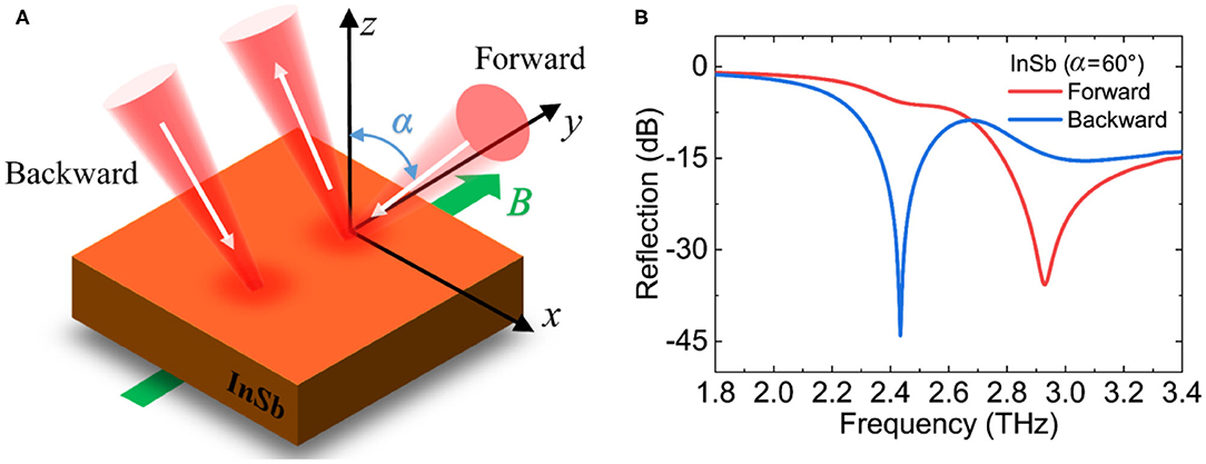
Figure 1. (A) Schematic diagram of the THz optical isolator for the InSb wafer with magnetic field along the y axis. A THz beam is incident in the x–z plane with the incident angle of α and is p-polarized. (B) The reflection spectrum of the forward wave and backward wave when α = 60° and B = 0.2 T.
We theoretically calculated the forward reflectance R(+α) = −20 × log[rp(+α)] and the backward reflectance R(−α) = −20 × log[rp(−α)] with the external magnetic field increases from 0 to 0.4 T when the oblique incidence angle α = 60, as shown in Figures 2A,C by using Equations (2–4). In the absence of an external magnetic field, εzx = −εxz = 0 and εxx = εyy, which leads to a reciprocal reflection R(+α) = R(−α) on the air/InSb interface. When the external magnetic field is applied, the incident THz waves are strongly resonant with the magnetized plasma on the surface of InSb, forming the magneto-plasmonic mode. This surface mode is localized on the dielectric/InSb interface and the incident THz waves cannot be reflected, so some dark blue regions occur in Figures 2A–D, which just correspond to the very low reflection of the magneto-plasmonic mode. More importantly, as the external magnetic field increases, this mode splits: the resonance mode of forward reflection gradually moves to the higher frequency, while the resonance mode of the backward reflection gradually moves to the lower frequency. A huge difference R(+α)≠R(−α) happens in the resonance frequency band at a certain magnetic field, which means a strong nonreciprocal reflection in the forward and backward directions defined as the isolation Iso = R(+α)−R(−α). Two different isolation bands for forward (yellow region) and backward (dark blue region) reflections are shown in Figure 2E, and the maximum isolation can be obtained under an external magnetic field of 0.2 T. Moreover, the forward reflectance, the backward reflectance and the isolation with the increase of the incident angle from 45 to 75° are shown in Figures 2B,D,F, when the external magnetic field is fixed at 0.2 T. The resonance and isolation peaks of the forward and the backward reflections gradually move to the high frequency.
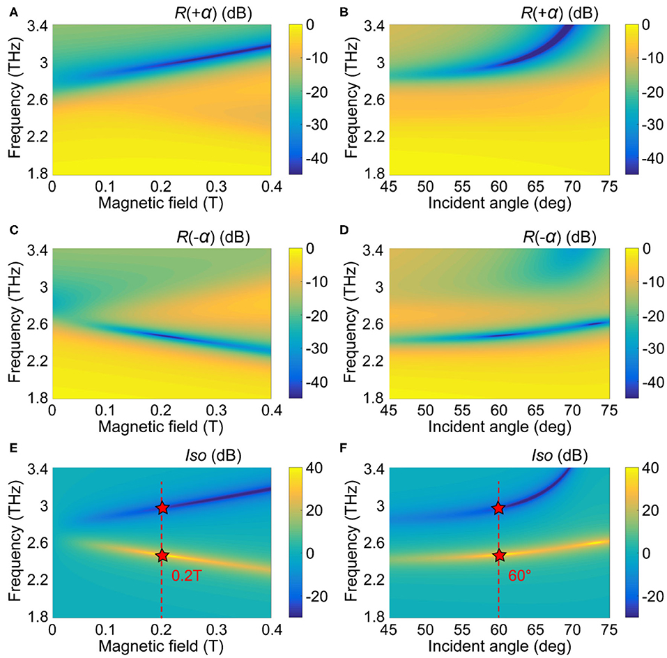
Figure 2. The calculated reflections of the forward R(+α) (A) and backward wave R(−α) (C), and the isolation Iso (E) for the InSb wafer with the different external magnetic fields at room temperature of 300 K when α = 60°. The calculated reflections of the forward R(+α) (B) and backward wave R(−α) (D), and the calculated isolation Iso (F) for the InSb wafer with the different incident angles at room temperature when B = 0.2 T.
The two key performance parameters of the isolator need to be pointed out: one is the insertion loss, which depends on the reflectance of the forward or backward beam; the other is the isolation between the forward reflectance and backward reflectance. A relatively large isolation can be achieved in Figure 2F with the incident angle of around 60 or 73°. Here, we choose the optimized incident angle of 60° with the comprehensive consideration of the insertion loss and isolation. The simulation results from CST simulation shown in Figure 1B indicate that a nonreciprocal reflection can be obtained in the InSb with the optimized oblique incident angle of 60° under a weak magnetic field of 0.2 T: the reflectance in the forward direction is high, and the backward traveling beam is absorbed by InSb, so that the reflectance in the backward direction is almost zero. At 2.434 THz, the isolation is Iso = R(+α)−R(−α) = 38.2 dB and the insertion loss R(+α) = −5.8 dB. Moreover, the isolation at 2.929 THz is Iso = R(−α)−R(+α) = 21.4 dB with the insertion loss R(−α) = −14.3 dB.
Nonreciprocal Reflectance of MO Microstructure by Combining InSb With Metasurface
Furthermore, we designed a THz optical isolator by combining InSb with metasurface, the magnetic field is applied along the y axis in the Voigt geometry, and the linear p-polarized THz wave is incident on the MO microstructure at a certain oblique incident angle α to achieve a nonreciprocal reflection, as shown in Figure 3A. A periodically patterned metasurface with a thickness of 200 nm is coated on the silica spacer layer with a thickness of d = 50 μm. The unit cell of the patterned metasurface is labeled in Figure 3B, and the unit cell period P = 60 μm along the x and y axis. The outside length of the square ring is l = 57 μm with the width is w = 2 μm. The diameter of the inner ring is D = 49 μm. The bottom layer is the InSb wafer substrate with a thickness of 500 μm.
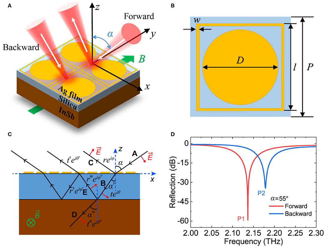
Figure 3. (A) Schematic diagram of the proposed THz optical isolator for the InSb with metasurface. (B) The geometry of the unit cell metasurface, P = 60 μm, l = 57 μm, w = 2 μm and D = 49 μm. (C) Multiple reflections and interference model of the proposed THz optical isolator for the InSb with metasurface. (D) The reflection spectrum of the forward wave and backward wave when α = 55° and B = 0.2 T.
As depicted in Figure 3C, the model contains two interfaces: the top air/metasurface interface and back dielectric/InSb interface. A plane wave incident upon the isolator at angle α. At the air/metasurface interface, the incident wave is divided into two parts, one of which is reflected into the air with a reflection coefficient , and the other transmits into the spacer with a transmission coefficient . The latter continues to propagate until it reaches the dielectric/InSb interface, with a complex propagation constant , where k0 is the wave vector in free space. Then the wave is transmitted to the dielectric/InSb interface at angle α′, which partially reflects back to the dielectric with a reflection coefficient and partially transmits into the InSb with a transmission coefficient . After that, the reflected wave occurs again at the air/metasurface interface with coefficients and . The overall reflection is the superposition of the multiple reflections and transmissions at the two interfaces: [35]
where the reflection coefficient r″ at the dielectric/InSb interface can also be derived by the Maxwell's equations and the continuity conditions for the fields and [34]. We then calculate the amplitude reflection coefficients and of the p- and s-polarized waves at the dielectric/InSb interface as follows, and the detailed derivation process can be found in Supplementary Material:
where α′ is the incidence angle to the dielectric/InSb interface (Figure 3C), is the refracted angle inside InSb given by Snell's law . The refracted angle in the p-polarization is different from and is given by the wave vector k = (ω/c)(sinα, 0, κ), where .
On account of the nonreciprocal dispersion of the magneto-plasmonic modes, the amplitude reflection coefficients for the p-polarized wave at the dielectric/InSb interface has the nonreciprocal effect (Equation 7), which further leads to an overall nonreciprocal reflection that superimposed of the multiple reflections and transmissions at the two interfaces (Equation 6). While the reflection coefficients for the s-polarized wave at the dielectric/InSb interface is reciprocal (Equation 8), and the overall reflection is reciprocal accordingly. The metallic metasurface and the InSb substrate form a resonance cavity to generate the multiple reflections between the two interfaces, and a destructive interference occurs between the direct reflection and the following multiple reflections when the amplitude and phase meet the matching conditions, so that a sharper resonance peak can be achieved in the reflection spectrum. The localization effect between metasurface and InSb enhances the nonreciprocal magneto-plasmonic modes on the InSb surface. Compared to pure InSb, the performance of the MO microstructure is improved with a lower operating frequency, a greater isolation, and a lower insertion loss, as shown in Figure 3D.
Similarly, we discuss the influence of the external magnetic field and the incident angle. Firstly, the incident angle is fixed at α = 55°, when the external magnetic field B = 0 T, the resonance peaks of the forward and the backward reflections are completely coincident, which means that the reflection exhibits reciprocal characteristics at this time. With the increase of the external magnetic field from 0 to 0.4 T, the resonance peak for the forward reflection gradually moves to the low frequency, as shown in Figure 4A. Meanwhile, the resonance peak for the backward reflection slightly moves to the high frequency, as shown in Figure 4C. Hence, the MO microstructure shows a nonreciprocal reflection, and the maximum isolation can be obtained under an external magnetic field of 0.2 T, as shown in Figure 4E. Then, we fixed the external magnetic field at 0.2 T, and the forward reflectance R(+α), the backward reflectance R(−α) and the isolation Iso as the incident angle increases from 40 to 70° are shown in Figures 4B,D,F. The results show that the resonance peaks for both the forward and the backward reflection gradually move to the low frequency, thus the isolation peaks gradually move to the low frequency. The maximum isolation can be achieved with an optimized incident angle of 55°. In this case, the isolation in 2.136 THz can be up to Iso = R(+α)−R(−α) = 55.38 dB with the insertion loss of R(+α) = −3.92 dB. Besides, the isolation at 2.178 THz is Iso = R(−α)−R(+α) = 28.94 dB with the insertion loss of R(−α) = −5.58 dB. It can be clearly seen that the MO microstructure based on InSb and metasurface has higher isolation and lower insertion loss than that of pure InSb, and its operating frequency to achieve nonreciprocal isolation is also reduced.
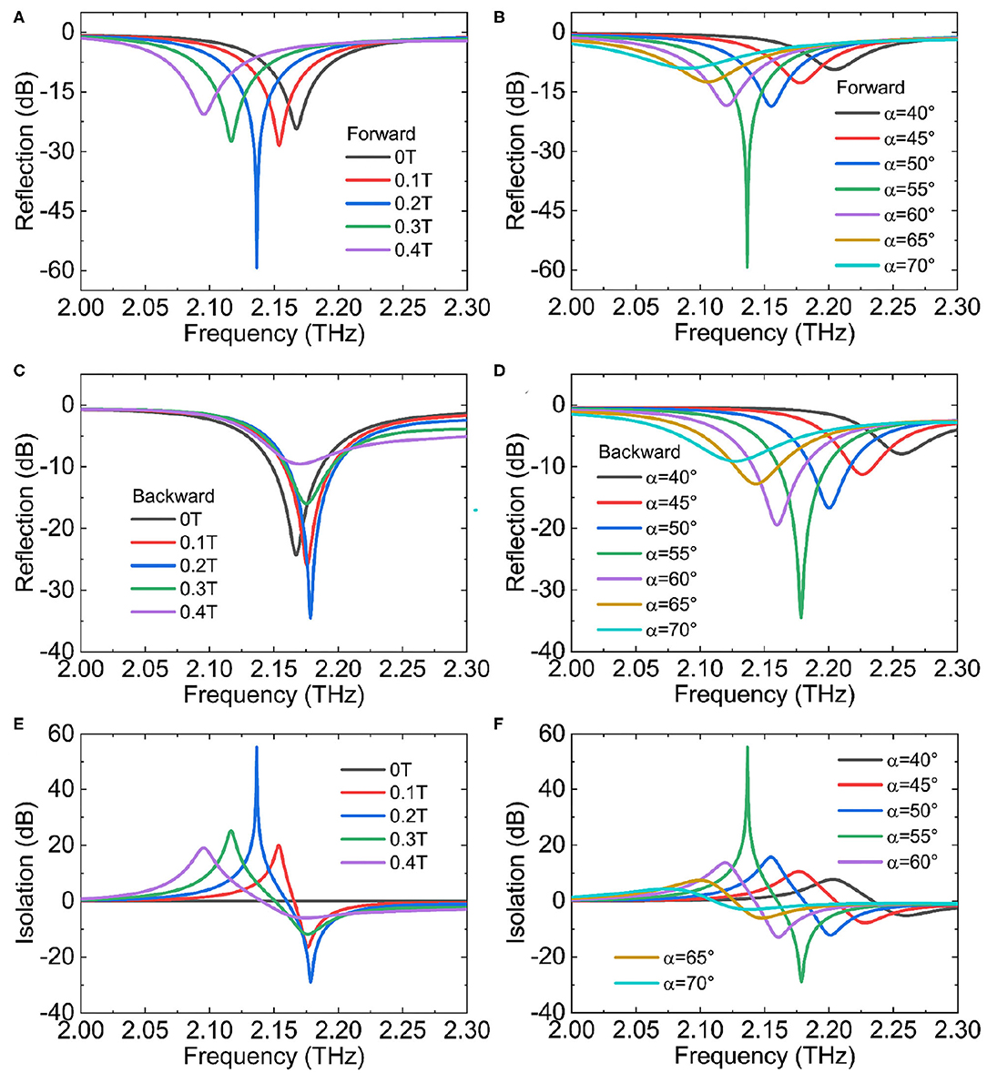
Figure 4. (A) Reflection spectra of the forward waves, (C) reflection spectra of the backward waves and (E) isolation spectra under the different external magnetic fields when α = 55° at room temperature. (B) Reflection spectra of the forward waves, (D) reflection spectra of the backward waves and (F) isolation spectra under the different incident angles when B = 0.2 T.
The near field distributions of forward and backward reflections are simulated to verify the nonreciprocal reflecting status of the MO microstructure by the FEM method from COMSOL. At 2.136 THz, the isolator only allows backward reflected light to pass through, and prohibits forward reflected light, as shown in Figure 5A. On the contrary, the isolator at 2.178 THz only allows forward reflected light to pass through, and prohibits backward reflected light, as shown in Figure 5B. The electric field distribution of the Ex component demonstrates the nonreciprocal reflection characteristics of the isolator, and the reflected angle is 55° in this case, as shown in Figure 5. It is worth mentioning here that the p-polarized reflected wave has not only the electric field of the Ex component but also the Ez component, and the electric field of the Ez component has similar distribution characteristics with the Ex component.
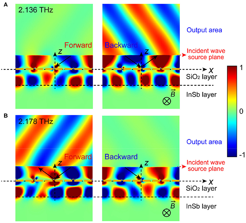
Figure 5. The schematic diagrams of the proposed THz optical isolator when α = 55° and B = 0.2 T at room temperature and the near field distribution of the Ex component: the forward wave experiences negligible reflectance and the backward wave experiences high reflectance at 2.136 THz (A); or the forward wave experiences high reflectance and the backward wave experiences negligible reflectance at 2.178 THz (B).
As previously mentioned, the occurrence of the resonance peak in the reflection spectrum is due to the destructive interference between the direct reflection and the following multiple reflections. Consequently, the resonance peak of the forward reflection is not at the same frequency as the backward reflection, thereby realizing a nonreciprocal isolation. This can be confirmed by the electric field patterns for the cutting plane and the spatial magnetic field distributions simulated in Figure 6. At 2.136 THz, for the forward wave, the electric field is mainly distributed at the interface of the metasurface and the dielectric layer between the metasurface and InSb, and the reflectance can be practically zero, indicating that the destructive interference occurs between the direct reflection at the metasurface/dielectric interface and the following multiple reflections. Hence, the wave can be effectively trapped in the cavity between the metasurface and InSb and the high absorption is achieved eventually. However, most of the waves are reflected at the metasurface/dielectric interface for the backward wave, whereas only a small part of the waves enters the dielectric layer, and the direct reflection and the following multiple reflections do not meet the conditions of destructive interference, consequently, the MO microstructure exhibits high reflectance, as shown in Figure 6A. On the contrary, at 2.178 THz, the destructive interference occurs in the backward wave, giving rise to a high absorption and a negligible reflectance, which is almost the same as the above case of the forward wave. Nevertheless, for the backward wave, although most of the waves enter the dielectric layer, the direct reflection and the following multiple reflections do not meet the conditions of destructive interference, which makes the MO microstructure exhibit high reflectance (Figure 6B).
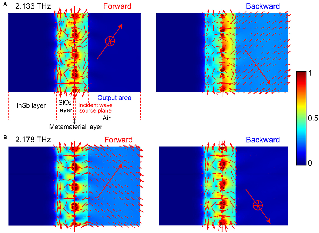
Figure 6. The electric field (color) and the magnetic field (arrows) distributions of the proposed THz optical isolator when α = 55° and B = 0.2 T at different frequencies: f = 2.136 THz (A) and f = 2.178 THz (B). THz waves are incident from the source plane to the MO microstructure (i.e., to the left), and then reflected by the MO microstructure. The reflected wave finally enters the air on the right side. The left side of the source plane is the total field distribution, including the incident field and the reflected field. The right side of the source plane is the pure reflected field distribution.
Recently, some THz isolators about chiral metamaterials have been reported [36, 37], the high-performance asymmetric transmission has been theoretically and experimentally demonstrated in bilayer chiral metamaterial, and the anisotropy and chirality of the metamaterial give rise to cross-polarization conversion. Although the reciprocal transmission device can achieve an asymmetrical one-way transmission when the light of the same polarization state is incident on the device in forward and backward directions, it cannot be used as an isolator. In contrast, the device in our work relies on the nonreciprocal characteristic of MO materials, and the MO non-reciprocal device can realize the function of one-way isolation transmission.
Conclusions
In summary, we explored the nonreciprocal reflectance of MO microstructure in the applied magnetic field in the Voigt geometry. The InSb magnetized by an applied magnetic field in the Voigt geometry has unique nonreciprocal magneto-plasmonic modes in the THz regime. On this bases, we introduce a resonant cavity between the InSb and metasurface, which is used to cause destructive interference between the direct reflection and the following multiple reflections, and eventually causes the high absorption, thereby generating a nonreciprocal strong resonance peak in the reflection spectrum and thus achieving a high-performance THz isolator. At the optimal incidence angle (55°) and the weak applied magnetic field (0.2 T) at room temperature, the isolation exceeds 55 dB, and the insertion loss is only −3.92 dB at 2.136 THz, which is significantly improved compared to the pure InSb. This nonreciprocal reflection mechanism and device structures can promote the development of THz isolators toward working at room temperature and low magnetic field with lower insertion loss and higher isolation.
Data Availability Statement
All datasets generated for this study are included in the article/supplementary material.
Author Contributions
YJ and FF designed the proposed structure of the isolator, performed the simulations and theoretical calculations as well as the results analysis. YJ carried out the writing of the paper. FF and SC provided the guideline of the research and modified the language of the manuscript. ZT helped to finish the simulations. All authors read and approved the final manuscript.
Funding
This work was supported by National Key Research and Development Program of China (2017YFA0701000); National Natural Science Foundation of China (61831012 and 61971242); Natural Science Foundation of Tianjin City (19JCYBJC16600); Young Elite Scientists Sponsorship Program by Tianjin (TJSQNTJ-2017-12).
Conflict of Interest
The authors declare that the research was conducted in the absence of any commercial or financial relationships that could be construed as a potential conflict of interest.
Supplementary Material
The Supplementary Material for this article can be found online at: https://www.frontiersin.org/articles/10.3389/fphy.2020.00334/full#supplementary-material
References
1. Ho L, Pepper M, Taday P. Terahertz spectroscopy: signatures and fingerprints. Nat Photonics. (2008) 2:541–3. doi: 10.1038/nphoton.2008.174
2. Cooper KB, Dengler RJ, Llombart N, Thomas B, Chattopadhyay G, Siegel PH. THz imaging radar for standoff personnel screening. IEEE Trans Terah Sci Tech. (2011) 1:169–82. doi: 10.1109/TTHZ.2011.2159556
3. Kleine-Ostmann T, Nagatsuma T. A review on terahertz communications research. J Infrared Millim Te. (2011) 32:143–71. doi: 10.1007/s10762-010-9758-1
4. Jin KH, Kim Y-G, Cho SH, Ye JC, Yee D-S. High-speed terahertz reflection three-dimensional imaging for nondestructive evaluation. Opt Express. (2012) 20:25432–40. doi: 10.1364/OE.20.025432
5. Mittendorff M, Li S, Murphy TE. Graphene-based waveguide-integrated terahertz modulator. ACS Photonics. (2017) 4:316–21. doi: 10.1021/acsphotonics.6b00751
6. Yang J, Gong C, Sun L, Chen P, Lin L, Liu W. Tunable reflecting terahertz filter based on chirped metamaterial structure. Sci Rep. (2016) 6:38732. doi: 10.1038/srep38732
7. Tan W, Zhang C, Li C, Zhou X, Jia X, Feng Z, et al. Selective coherent perfect absorption of subradiant mode in ultrathin bi-layer metamaterials via antisymmetric excitation. Appl Phys Lett. (2017) 110:181111. doi: 10.1063/1.4983087
8. Chang C-C, Zhao Z, Li D, Taylor AJ, Fan S, Chen H-T. Broadband linear-to-circular polarization conversion enabled by birefringent off-resonance reflective metasurfaces. Phys Rev Lett. (2019) 122:237401. doi: 10.1103/PhysRevLett.123.237401
9. Fan F, Chang SJ, Gu WH, Wang XH, Chen AQ. Magnetically tunable terahertz isolator based on structured semiconductor magneto plasmonics. IEEE Photonics Technol Lett. (2012) 24:2080–3. doi: 10.1109/LPT.2012.2219858
10. Shalaby M, Peccianti M, Ozturk Y, Morandotti R. A magnetic non-reciprocal isolator for broadband terahertz operation. Nat Commun. (2013) 4:1558. doi: 10.1038/ncomms2572
11. Fan F, Chen S, Chang SJ. A review of magneto-optical microstructure devices at terahertz frequencies. IEEE J Sel Top Quantum Electron. (2017) 23:8500111. doi: 10.1109/JSTQE.2016.2537259
12. Ghaffar FA, Bray JR, Vaseem M, Roy L, Shamim A. Theory and design of tunable full-mode and half-mode ferrite waveguide isolators. IEEE Tran Magn. (2019) 55:4003408. doi: 10.1109/TMAG.2019.2910028
13. Hilico L, Douillet A, Karr JP, Tournié E. Note: a high transmission Faraday optical isolator in the 9.2 μm range. Rev Sci Instrum. (2011) 82:096106. doi: 10.1063/1.3640004
14. Shuvaev AM, Astakhov GV, Pimenov A, Brune C, Buhmann H, Molenkamp LW. Giant magneto-optical faraday effect in HgTe thin films in the terahertz spectral range. Phys Rev Lett. (2011) 106:107404. doi: 10.1103/PhysRevLett.106.107404
15. Arikawa T, Wang XF, Belyanin AA, Kono J. Giant tunable Faraday effect in a semiconductor magneto-plasma for broadband terahertz polarization optics. Opt Express. (2012) 20:19484–92. doi: 10.1364/OE.20.019484
16. Shimano R, Yumoto G, Yoo JY, Matsunaga R, Tanabe S, Hibino H, et al. Quantum Faraday and Kerr rotations in graphene. Nat Commun. (2013) 4:1841. doi: 10.1038/ncomms2866
17. Tamagnone M, Moldovan C, Poumirol J-M, Kuzmenko AB, Ionescu AM, Mosig JR, et al. Near optimal graphene terahertz non-reciprocal isolator. Nat Commun. (2016) 7:11216. doi: 10.1038/ncomms11216
18. Shalaby M, Peccianti M, Ozturk Y, Clerici M, Al-Naib I, Razzari L, et al. Terahertz Faraday rotation in a magnetic liquid: high magneto-optical figure of merit and broadband operation in a ferrofluid. Appl Phys Lett. (2012) 100:241107. doi: 10.1063/1.4729132
19. Poumirol JM, Liu PQ, Slipchenko TM, Nikitin AY, Martin-Moreno L, Faist J, et al. Electrically controlled terahertz magneto-optical phenomena in continuous and patterned graphene. Nat Commun. (2017) 8:14626. doi: 10.1038/ncomms14626
20. Lin S, Silva S, Zhou JF, Talbayev D. A one-way mirror: high-performance terahertz optical isolator based on magnetoplasmonics. Adv Opt Mater. (2018) 6:1800572. doi: 10.1002/adom.201800572
21. Tan Z, Fan F, Chang S. Active broadband manipulation of terahertz photonic spin based on gyrotropic pancharatnam-berry metasurface. IEEE J Sel Top Quantum Electron. (2020) 26:1–8. doi: 10.1109/JSTQE.2020.2984560
22. Li T-F, Li Y-L, Zhang Z-Y, Yang Q-H, Fan F, Wen Q-Y, et al. Terahertz Faraday rotation of magneto-optical films enhanced by helical metasurface. Appl Phys Lett. (2020) 116:251102. doi: 10.1063/5.0009704
23. Hu B, Wang QJ, Zhang Y. Broadly tunable one-way terahertz plasmonic waveguide based on nonreciprocal surface magneto plasmons. Opt Lett. (2012) 37:1895–7. doi: 10.1364/OL.37.001895
24. Chen S, Fan F, Wang X, Wu P, Zhang H, Chang S. Terahertz isolator based on nonreciprocal magneto-metasurface. Opt Express. (2015) 23:1015–24. doi: 10.1364/OE.23.001015
25. Fan F, Xiong CZ, Chen JR, Chang SJ. Terahertz nonreciprocal isolator based on a magneto-optical microstructure at room temperature. Opt Lett. (2018) 43:687–90. doi: 10.1364/OL.43.000687
26. Yu SK, Heffernan KH, Talbayev D. Beyond the effective mass approximation: a predictive theory of the nonlinear optical response of conduction electrons. Phys Rev B. (2017) 95:125201. doi: 10.1103/PhysRevB.95.125201
27. Han JG, Lakhtakia A, Qiu CW. Terahertz metamaterials with semiconductor split-ring resonators for magnetostatic tunability. Opt Express. (2008) 16:14390–6. doi: 10.1364/OE.16.014390
28. Brion JJ, Wallis RF, Hartstein A, Burstein E. Theory of surface magnetoplasmons in semiconductors. Phys Rev Lett. (1972) 28:1455–8. doi: 10.1103/PhysRevLett.28.1455
29. Hu B, Zhang Y, Wang QJ. Surface magneto plasmons and their applications in the infrared frequencies. Nanophotonics. (2015) 4:383–96. doi: 10.1515/nanoph-2014-0026
30. Wang X, Belyanin AA, Crooker SA, Mittleman DM, Kono J. Interference-induced terahertz transparency in a semiconductor magneto-plasma. Nature Phys. (2010) 6:126–30. doi: 10.1038/nphys1480
31. Mu QY, Fan F, Chen S, Xu ST, Xiong CZ, Zhang X, et al. Tunable magneto-optical polarization device for terahertz waves based on InSb and its plasmonic structure. Photon Res. (2019) 7:325–31. doi: 10.1364/PRJ.7.000325
32. Oszwałldowski M, Zimpel M. Temperature dependence of intrinsic carrier concentration and density of states effective mass of heavy holes in InSb. J Phys Chem Solids. (1988) 49:1179–85. doi: 10.1016/0022-3697(88)90173-4
33. Rivas JG, Janke C, Bolivar PH, Kurz H. Transmission of THz radiation through InSb gratings of subwavelength apertures. Opt Express. (2005) 13:847–59. doi: 10.1364/OPEX.13.000847
34. Remer L, Mohler E, Grill W, Lüthi B. Nonreciprocity in the optical reflection of magnetoplasmas. Phys Rev B. (1984) 30:3277–82. doi: 10.1103/PhysRevB.30.3277
35. Chen HT, Zhou JF, O'hara JF, Chen F, Azad AK, Taylor AJ. Antireflection coating using metamaterials and identification of its mechanism. Phys Rev Lett. (2010) 105:073901–4. doi: 10.1103/PhysRevLett.105.073901
36. Shi J, Liu X, Yu S, Lv T, Zhu Z, Ma HF, et al. Dual-band asymmetric transmission of linear polarization in bilayered chiral metamaterial. Appl Phys Lett. (2013) 102:191905. doi: 10.1063/1.4805075
Keywords: terahertz, isolators, magneto-optical device, metamaterials, surface plasmon
Citation: Ji Y, Fan F, Tan Z and Chang S (2020) Terahertz Nonreciprocal Isolator Based on Magneto-Plasmon and Destructive Interference at Room Temperature. Front. Phys. 8:334. doi: 10.3389/fphy.2020.00334
Received: 13 February 2020; Accepted: 20 July 2020;
Published: 26 August 2020.
Edited by:
Lin Chen, University of Shanghai for Science and Technology, ChinaReviewed by:
Shen Xiaopeng, China University of Mining and Technology, ChinaJinhui Shi, Harbin Engineering University, China
Copyright © 2020 Ji, Fan, Tan and Chang. This is an open-access article distributed under the terms of the Creative Commons Attribution License (CC BY). The use, distribution or reproduction in other forums is permitted, provided the original author(s) and the copyright owner(s) are credited and that the original publication in this journal is cited, in accordance with accepted academic practice. No use, distribution or reproduction is permitted which does not comply with these terms.
*Correspondence: Fei Fan, ZmFuZmVpX2dkekAxMjYuY29t; Shengjiang Chang, c2pjaGFuZ0BuYW5rYWkuZWR1LmNu
 Yunyun Ji1,2
 Fei Fan