 Tony Gerges
 Vincent Semet1
 Simon Auguste Lambert
- 1Université de Lyon, INSA Lyon, Université Claude Bernard Lyon 1, Ecole Centrale de Lyon, CNRS, Ampère UMR5005, Villeurbanne, France
- 2Université de Lyon, INSA Lyon, Université Claude Bernard Lyon 1, UJM-Saint Etienne, CNRS, Inserm, CREATIS UMR 5220, U1206, Lyon, France
Over the last four decades, magnetic resonance imaging has become the gold standard imaging technique in many medical diagnoses for brain, cardiac, and liver disease. However, due to low critical mass and great scientific challenges, instrumentation dedicated to preclinical MRI imaging has lagged behind instrumentation for clinical applications. The aim of this paper is to demonstrate that a set of new technologies such as the 3D Molded Interconnect Devices technology preferably named below as 3D Plastronics, 3D Printing, and Microfluidics may be considered to provide a completely new way for designing preclinical MRI setups, i.e., the 3D prototyping and manufacturing of the MR coil, the sample holder, and the peripherals, all together. The fabricated MRI setup can be used both for MRI of small biological samples and for in vivo imaging of a mouse brain. This work is the first step toward the full 3D manufacturing of tailor-made multifunctional MRI probes.
Introduction
Over the last four decades, magnetic resonance imaging (MRI) has become the gold standard imaging technique in many medical diagnoses related to brain [1], cardiac [2], and liver disease [3]. MRI techniques are used both in clinical and preclinical studies to non-invasively visualize and quantify alterations of biological tissues at different spatial and time scales. More recently, there has been growing interest in multiparametric acquisitions in order to assess the complexity of heterogeneous biological tissue changes involved in target diseases. In this context, the fast and tremendous advances in MRI have been possible thanks to huge technological developments leading to a substantial increase of the signal to noise ratio (SNR) obtained either by an increase of the static magnetic field intensity [4] or by the development of new radiofrequency (RF) coils [5]. The frontiers of the technology are constantly pushed back. For example, phased array coils with up to 128 small surface coils which allow increased SNR and reduced scan durations have been manufactured [6–9]. However, due to low critical mass and great scientific challenges, instrumentation dedicated to preclinical MRI imaging has lagged behind instrumentation for clinical applications [10]. In fact, working with preclinical MRI implies working with smaller coils operating at higher frequency than clinical coils. This leads to reduced SNR due to higher electric and sample losses, and tunability becomes more of an issue. Therefore, the main goal of this work is to provide a new set of low cost and adaptable manufacturing tools in order to facilitate the development of a dedicated preclinical MRI setup.
To achieve this goal, we have to take into account that MRI of small in vitro, ex vivo, and in vivo samples require specialized MR setups that must satisfy specific constraints. In order to reach high spatial resolution images with high SNR, the development of highly sensitive small MR coils with forms fitting to the complex 3D shape of the samples is required. This domain corresponds to the so-called “mid-range coils” where the product of the actual frequency by the coil diameter is in the 2–30 MHz-m range. It is known that MR coil losses are not negligible compared to sample losses and must be minimized in order to maximize the SNR [10]. Moreover, in preclinical imaging of small samples, additional sensors or actuators, called peripherals, must be used in order to regulate physiological and environmental conditions to ensure viability of tissue or good animal care over the MRI examination time. To fulfill the space occupation requirements, the MRI setups must be designed such that they smartly integrate these peripherals within the MRI coil in a compact manner, as well as the need for tuning and matching devices.
To date, development of preclinical MRI setups dedicated to a specific application consist of using commercial MR coils available at an MR facility that fits as much as possible to the sample. Then, the fixation of the sample and the integration of peripherals within the MR coil rely on poorly reliable methods, such as tape, for instance. Therefore, new strategies must be used to facilitate the development of customized MRI setups for preclinical applications which take into account all of the different constraints. First of all, conventional electronics technology (mainly based on 2D rigid printed boards made of FR4 polymer material) does not offer the possibility to manufacture MR coils with a 3D complex geometry, which is needed to maximize the filling factor (i.e., the ratio of magnetic field energy stored inside the sample volume vs. the total magnetic energy stored in the coil) and the radiofrequency magnetic field homogeneity. In addition, dedicated holders are needed to prevent any motion of the sample, which is mandatory for high spatial resolution imaging. These specifications are obtained, if any, by conventional machining (milling, forming, etc.) available at mechanical workshops. However, these techniques are expensive and lack the scalability and adaptability required to design dedicated MRI setups for many different specific preclinical experiments. Moreover, the limited space available in preclinical MR scanners has to be taken into account when considering the mechanical assembly of the MRI setup together with the constraints in terms of MRI compatibility (material compatibility with high magnetic field, reduced uncontrolled coupling between electrical conductors, etc.). Finally, contrary to clinical MRI where sample noise is dominating due to the use of large MR receive coils placed close to the body, in preclinical imaging a greater proportion of noise compared to sample noise can reduce the MR coil sensitivity. Therefore, choice of coil material (conductive and dielectric materials), design (width, spacing, and thickness of conductive tracks) and manufacturing process (surface roughness required to deposit conductive tracks) becomes critical [11].
Taking into account all these requirements, the aim of this paper is to demonstrate that a set of new technologies such as the 3D Molded Interconnect Devices technology (3D MID) [12], preferably named below as 3D Plastronics, 3D Printing [13] and Microfluidics [14], may be considered to provide a completely new way for designing preclinical MRI setups, i.e., the 3D prototyping and manufacturing of the MR coil, the sample holder, and the peripherals, all together.
3D Plastronics is a fast growing field that aims to implement electronic functions directly on the surface of 3D polymer substrates. 3D conductive tracks are structured to interconnect electronic components, such as Surface Mount Devices (for example capacitors in this work), which are soldered on the surfaces. In some cases, such as in this work, the 3D conductive tracks can be directly used [antennas [15], inductances [16], eddy current sensor [17], etc.]. 3D Plastronics allows improved integration of heterogeneous functions (mechatronic, optical, thermal, fluidic, etc.) in the packaging of the devices, which is no longer limited to mechanical functions. This technology is already being used in the design of 3D antennas [18], microfluidics [19], pH sensors [20], physical sensors, and optical assemblies [21]. The technology allows a greater freedom in three-dimensional design, for example, 3D antennas or even 3D arrays of 3D inductances [17]. Different technologies are available to manufacture plastronic devices, such as Laser Direct Structuring (LDS) [22], two-shot injection molding [23], In Mold Electronics (IME) [24, 25], 3D microcontact printing [26], laser substractive structuring [27], aerosol jet [28, 29], and direct ink writing [30]. Often the fabricated devices are named “3D-Molded Interconnect Devices” (3D-MID), although (according to us) 3D-MID should only refer to the LDS process (see [12] for a review on LDS). Plastronic devices can be mass produced, but this subject is outside of the scope of this paper.
In this paper, we describe prototyping the plastronic devices for the production of small series as requested by the targeted application field. This consists of manufacturing the 3D polymer substrates by 3D printing (for example by stereolithography SLA or fused deposition modeling FDM) and structuring the conductive network by means of a modified LDS process using a lacquer [ProtoPaint process [12]] or by ink jetting or robot casting of conductive material. The former has the disadvantage of making use of an expensive laser based machine, while the latter makes use of conductive materials with poor conductivity [typically 40% of the conductivity of bulk silver [31]]. In addition, with ink jetting, it is difficult to define conductive tracks on sloped parts due to the low viscosity of inks (typically 1–20 cp). Therefore, it is important to develop low cost and flexible technologies for prototyping plastronic devices and to demonstrate their capability.
The aim of this manuscript is to describe how to prototype 3D plastronic devices in the field of preclinical MRI with low cost and adaptable techniques. The 3D substrates supporting the coils are obtained by 3D printing and the coils and conductive interconnexions are directly implemented by a combination of electroless deposition and electrodeposition steps. The feasibility of metalizing 3D printed substrates is demonstrated by developing a volume coil dedicated to both small in vitro/ex vivo samples and in vivo mouse brain imaging. As an example of peripheral integration, temperature monitoring of the animal when using the coil for in vivo brain imaging is performed by use of 3D printed fluidic system allowing circulation of hot water. Special effort is focused on positioning the samples as well as the mouse for brain in vivo imaging.
Materials and Methods
Overview of the MRI Set Up and Fabrication Process
The 3D plastronic device for MRI imaging of small samples and rodent brains (also called below MRI setup) is shown in Figure 1. It consists of a Helmholtz coil, which demarcates the sample space, and a coupling loop, whose vertical position can be adjusted in order to match the Helmholtz coil impedance to the one of the receiver channel of the MRI machine.
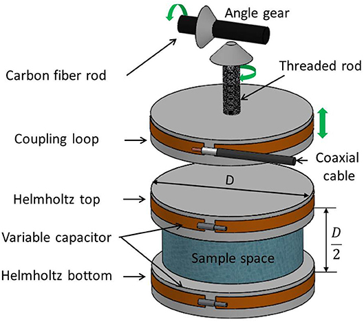
Figure 1. 3D plastronic MR coil composed of three metallized parts: the Helmholtz bottom and top coils and the coupling loop. Helmholtz bottom and top coils are inductively coupled and are tuned with variable capacitors in order that the ensemble, i.e., the Helmholtz coil, is resonating at the Larmor frequency. The distance from the coupling loop to the Helmholtz coil can be manually adjusted through a mechanical shaft (threaded rod, angle gear, and shank) in order to match MR coil impedance to one of the receiver channels (the green arrow shows motion direction of the coupling loop, the threaded rod, and the shank).
The MRI setup is dedicated to small samples and rodent brain imaging. In Figure 2, the sample to be imaged is an anesthetized mouse placed in the prone position on a heated bed. The bottom Helmholtz coil fits in this bed so that the mouse head lays on it. The installation of the animal is performed manually by the operator (direction of motion of mobile parts are indicated by green arrows). During the installation (Figure 2A), the movement of the heating bed onto a support base is guided laterally by a dovetail, whilst the top Helmholtz coil is lifted in order to leave sufficient space for the head of the mouse. After sliding the heating bed so that the head of the animal is in the imaging volume, the top Helmholtz coil can be lowered so that the mouse is maintained by the neck (Figure 2B). A coaxial cable is connected at one end to the coupling loop and at the other end to a RF SMB connector. For imaging, the MRI setup can be placed in the middle of the MRI bore and connected by means of the RF SMB connector through a coaxial cable to the reception channel of the MRI system. It is noteworthy that no tape is used to maintain the animal. When in vitro/ex vivo imaging is required, a small vat (26 mm diameter, 15 mm height) filled with the sample can be easily placed in the Helmholtz coil instead of the mouse head.
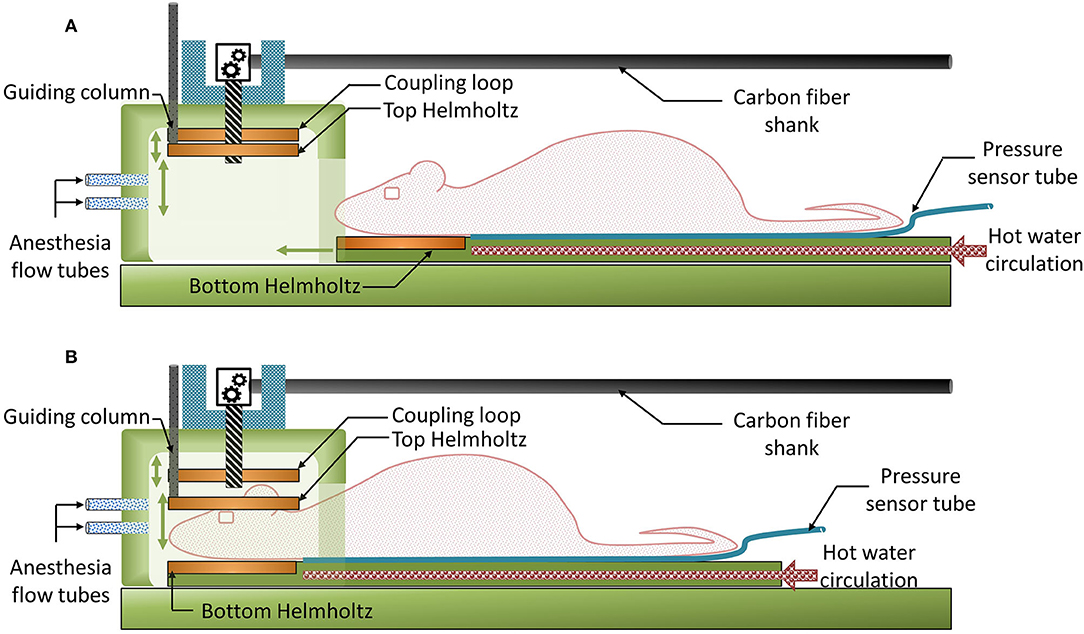
Figure 2. 2D operating diagrams of the 3D plastronic MRI set-up. (A) The top Helmholtz coil can be lifted in order to leave sufficient space for the head of the mouse (or the sample). (B) After sliding the heating bed so that the head of the animal is in the imaging volume, the top Helmholtz coil can be lowered so that the mouse is maintained by the neck.
Except for a few elements, which require being precisely adjusted (see below), the components of the MRI setup have been manufactured by 3D printing, mostly by stereolithography (SLA). In effect, we decided to minimize the use of Fused Deposition Modeling (FDM) because of the poor surface roughness of the parts manufactured with this process and also because of their poor accuracy, which makes the realization of a complex assembly difficult.
Two methods have been compared for the copper deposition on the surface of the 3D substrates. The first one consists of using copper tapes and was considered as the reference as the MR coil is made of bulk copper. The second one consists of using electroless deposition (ELD) for metallizing the entire surface of the 3D parts and then removing locally the unwanted copper, to define the conductive tracks. The advantage of using copper tape instead of flexible FR4 or copper wire is that the trace geometries are exactly the same for both copper deposition process (a little difference between trace thickness) and there is no additional dielectric (dielectric substrate). The only difference is hence the quality of the copper deposit that will be estimated in the present work by measurements on the bench and by imaging.
Description of the MR Coil
The MR coil used in the present work was a volume coil based on a Helmholtz design for two reasons: (i) it requires soldering of only a few capacitors compared to birdcage coil and (ii) the homogeneity of the RF field (B1) is sufficient to perform experiments in transmit/receive mode. As discussed below, several metallization processes could thereby be easily tested and validated by a RF characterization step on the bench followed by MRI examination. The iteration steps between fabrication and characterization were hence simplified.
The Helmholtz coil was composed of two circular inductively coupled parts and resonated at two frequencies corresponding to the two coupling modes of the Helmholtz coil. The lower resonant frequency corresponds to the currents having the same direction in both loops (i.e., the imaging mode), whereas the upper resonant frequency corresponds to the currents having opposite directions (i.e., the gradient mode). Each part was tuned using a fix (ATC 100B8R2DTN500) and a variable capacitor (TG 091 ROHS, Exxelia, France) for fine tuning in order to set the frequency of the lower frequency to the proton Larmor frequency, i.e., here 200 MHz. The distance between the two parts was equal to half the diameter of one loop (∅), in order to ensure good RF field homogeneity. A small diameter and flexible coaxial cable (RG316) was soldered to the coupling loop and the other extremity to a RF SMB connector that was integrated on top of the packaging chamber. The MR coil was connected to the receiver channel of the MR system by plugging a half wavelength coaxial cable to this connector. This cable length was chosen to minimize wave reflections and hence RF losses within the cable. No cable trap was integrated to suppress common mode currents. Nevertheless, good stability of the coil was observed during bench and imaging experiments.
The Helmholtz coil was inductively coupled to the transmit-receive switch inside the scanner's RF output box using a coupling loop (Figure 2A) placed on top of the upper Helmholtz coil. The distance of coupling loop to the upper Helmholtz coil had to be vertically adjusted to match the coil to 50 Ω. This was performed by the operator by means of a mechanical shaft, made of 80 cm long carbon fiber shank, with one end outside the bore of the MRI magnet [32]. The other end side of the shank, inside the bore of the MRI magnet, was connected to an angle gear made of two plastic bevel gears orthogonally oriented and connected to a vertical threaded plastic rod (5 mm diameter, 1 thread/mm) (Figure 3). As a result, vertical motion of the coupling loop was easily performed by manually turning the carbon fiber shank. It is worth noting that the carbon fiber shank, the gears, the threaded rod, and their supporting bracket are the only non-SLA parts of the device since they have to be precise parts. The rod was threaded at the mechanical workshop of the University to ensure good manufacturing precision and assembly of the angle gear in order to achieve smooth movement.
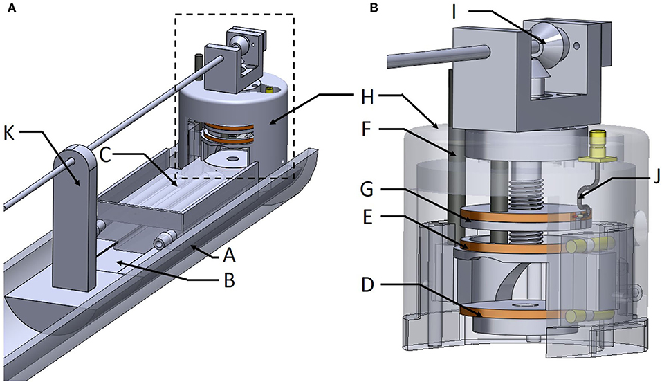
Figure 3. The whole MRI setup (A) and the MR coil integrated within the packaging chamber for better confinement of the sample, which facilitates temperature and/or anesthesia monitoring (B).
Description of the MRI Setup
As mentioned in the introduction, designing RF coils for preclinical imaging must satisfy stringent requirements in term of space occupation, filling factor, and tuning/matching devices. Therefore, dimensioning and integration of the Helmholtz coil in a functional and easy way to handle the MRI setup for small in vitro/ex vivo and in vivo mouse brain imaging was a critical step in this work. To this end, as the envisioned device had to be able to image a mouse brain in vivo, the loop diameter was set to 30 mm so that the distance d between the loops was 15 mm. This provides enough space for positioning the mouse's head at the center of the Helmholtz coil and maximizing the filling factor.
The 3D design of the MRI setup which integrates the Helmholtz coil and the fluidics and sensors is presented on Figures 3A,B. One half tube of PMMA (Part A) is used as the main support for the device and is screwed on a positioning table with three linear axes of translation. Thus, it is possible to align the device with the MRI magnet bore and place it at the right position for imaging. Part B is a guideway support base, glued to part A, to provide stable basic support for the samples and the coil. Part C is the heating bed with the guiding dovetail and the bottom Helmholtz coil (Part D). Part E is the top Helmholtz coil which is bored to allow guiding with a vertical column (Part F). This feature allows lifting of the top of the Helmholtz coil (about 5 mm) when placing the mouse's head in the instrument. Part G is the coupling loop already described above. Part H allows covering the Helmholtz coil with a packaging chamber for better confinement of the sample, which facilitates temperature and/or anesthesia monitoring. Anesthesia inlets were integrated on this chamber and facing the nose of the animal. The angle gear (Part I) is fixed on top of this packaging chamber. The coaxial cable (Part J) is soldered on a SMB board-to-board connector (903-305J-51R, Amphenol®, USA) fixed also on the top of this chamber. Part K is a support for the carbon fiber shank. Parts B to H have been printed using a stereolithography process (Form 2 printer–Formlabs) with high temperature resin (FLHTAM02); the supports were manually removed using a flush cutter. Otherwise, Part K has been printed using fused deposition modeling (FDM) process and a soluble support (HIPS) was used.
Metallization of the Coils
As explained above, two methods of metallization are compared. The first one makes use of copper tape (AT525, Advance Tapes, UK) cut, wrapped, and glued around the 3D SLA parts. The thickness of the copper was measured at 35 μm by X-ray fluorescence (Bowman).
The second method is summarized in Figure 4 with the upper Helmoltz coil as an example. The part is SLA printed (Figure 4A). After cleaning of the part, removal of the supports typically used in SLA manufacturing, and postcuring, the part is metallized by Electroless Deposition (ELD) of copper. This consists of immersing the part in a palladium catalyst solution (Macuplex Activator-D34C, MacDermid), rinsing in water, and plating in an electroless copper bath (Mid Copper 100XB, MacDermid) for about 120 min. As a result, the 3D outside surface of the part is entirely metallized with copper with a 5–6 μm typical thickness (Figure 4B). The next step is to delineate the conductive tracks. For this, scotch tape is cut and put on the part to protect the coil surface (Figure 4C) and the part is etched with a solution of ferric chloride (Bernier P-2035L) for 5 min at 30°C to remove the unwanted copper. After cleaning and drying, the final part is the 3D substrate with a copper coil (Figure 4D). From a previous study, it is known that increasing the thickness of the electroless copper improves SNR by decreasing the AC resistance and thus increasing the quality factor, which is inversely propotional to this resistance [17]. Therefore, the thickness of the copper is enhanced by electrolytic deposition of Cu: the part is placed into a 220 g/l copper sulfate (CuSO4) solution, with 3.1% sulphuric acid (H2SO4), 0.2 ml/l Hydrochloric acid (HCl), and brilliance additives (2 ml/l Rubin T200-A, 8 ml/l Rubin T200-G and 2 ml/l Rubin T200-E). A concentric cylindrical copper electrode is placed around the part at 10 mm, approximately. A 10 mA/cm2 current is supplied for 2 h between the electrode and the coil surface, to obtain 25 μm of additional copper thickness.
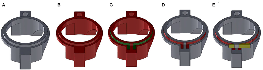
Figure 4. Overview of the fabrication process for a plastronic coil as exemplified for the Helmholtz top coil. (A) SLA printed part. (B) Metallization of the entire outside surface of the part with electroless copper (red). (C) Definition of the position of the coil with protective scotch tape (green). (D) Part after etching with ferric chloride showing the copper coil (red). (E) Final part after soldering of the variable capacitor (yellow) to tune the coil resonance.
At this stage, the overall thickness of the copper layer (measured by X-ray fluorescence [Bowman]) is in the 30 μm range (see below).
Lastly, when using high temperature SLA resin, it is possible to directly solder the capacitors or the connecting cable (Figure 4E).
Small Animal Heating System and Its Thermal Characterization
A system for homoeothermic maintenance of a small animal was integrated in the MRI setup, which was based on the circulation of hot water in a serpentine fluidic system inside the mouse bed (Part C of Figure 3). This part was directly 3D printed with a circular section of 3.5 mm diameter inside the mouse bed. Temperature and flow monitoring of water were performed using a 4100B Fisherbrand bath circulator connected to the mouse bed via flexible silicon tubes plug on 3D printed inlets. The heating performance of the animal bed was characterized by thermal imaging with a Fluke Ti480 Pro Infrared Camera, which provides a temperature map of the bed.
Coil Characterization on Bench
Unloaded (QU) and loaded (QL) quality factors were measured using the single loop probe method [33]. This characterization step was required to verify the quality of the copper deposit of each element of the Helmholtz coil before characterization of the assembly of the 2 loops, i.e., the Helmholtz coil. The coil was loaded with a 0.9% sodium solution to mimic the loading effect of small samples such as a mouse brain. As introduced in [34], loop efficiency (QU/QL), noise power ratio (NPR), and noise figure of the coil (NF) were defined as follows:
NF measures the SNR decrease attributable to losses in the coil which means that a lossless coil has NF=0. Thus, this parameter is beneficial to study the quality of our manufacturing process to build coils.
QU and QL of the assembled Helmholtz coil were also measured connecting the coupling loop to a network analyzer to perform s11 measurements. RF characterization of the Helmholtz coil through the coupling loop was needed to estimate the imaging performance of the MR coil. As explained in [35], particular attention was paid to accurately determine the −3 dB level by decreasing the power level of the VNA and using an adapted frequency span. Then the intrinsic Q of the Helmholtz coil with the coupling loop was twice the Q measured at the −3 dB level.
Coil Characterization by Imaging of a Homogeneous Agarose Phantom
The different coils were characterized in imaging conditions on a 4.7 T magnet. Phantoms were made with 1.5% agarose powder (Sigma A9414) diluted in 0.9% sodium chloride solution to mimic load effect of small samples such as a mouse brain. To estimate imaging performances of the MR coil, SNR measurements were performed using a 3D Flash sequence with parameters reported in Table 1. SNR measurements for the phantoms were extracted from magnitude images using the average signal intensity over a region of interest (ROI) in the agarose gel and the standard deviation in the background ROI. The ROI in the phantom was a cubic ROI centered onto the phantom region. The background ROI was set into the lowest-noise region along the frequency-encoding axis. Before imaging, tuning and matching of the MR coil were checked using the “Wobble” procedure of the Bruker system. The tuning and matching were adjusted manually using a ceramic screwdriver and turning the carbon fiber shank, respectively.
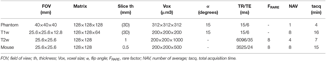
Table 1. Sequence parameters used to measure SNR on phantom, to acquire ex vivo lamb's kidney T1 weighted (T1w) and T2 weighted (T2w) images, and in vivo imaging of one mouse.
Ex vivo Imaging of a Lamb's Kidney
Imaging of a lamb's kidney was performed using the coil metallized with the electroless manufacturing process to serve as an illustration. A piece of lamb's kidney was immersed in sodium chloride solution to limit degradation of tissues during the MR examination time. Two MR sequences were performed: one T1-weighted 3D Flash sequence (T1w) and one T2-weighted RARE sequence (T2w). Sequence parameters are reported in Table 1. The MR coil was operated in transmit/receive mode.
In vivo Imaging of a Mouse Brain
Adult male “strain” mice (30–40 days) were obtained from Charles River (L'Arbresle, France). Prior to the examination, the mice were housed “3 to 4” per cage, in a 300 cm2 plastic cage with straw bedding under standard laboratory conditions (22°C, 12-h light/dark cycles). Animals had access to food and water ad libitum.The experiments were in accordance with the rules and regulations of the Université Claude Bernard Lyon 1 Ethics Committee on animal experimentation. Mice were anesthetized using an isoflurane tabletop station (TEM Sega®, Lormont, France). The respiratory index was monitored during the experimentation by using a pressure sensor placed on the mouse bed in contact with the mouse abdomen. During the induction phase, mice were anesthetized with 3% of isoflurane vaporized in air, and the aspiration flow was set up on 0.4 L/min. During imaging, the anesthesia was maintained with 1.4–1.7% isoflurane vaporization and aspiration flow set up on 0.4 L/min. Mice were scanned longitudinally across post-scanning. The MR examination was started by a localizer to obtain brain location and orientation. Then a 2D-RARE sequence was acquired with the parameters reported in Table 1. Finally, mice were transferred to a heated cage for 5–10 min in order to recover from anesthesia, and then returned to their home cages.
Results
Fabrication of the MRI Setup
3D designs of the different parts of the MR coil and pictures of the corresponding manufactured parts are presented in Figure 5. The coupling loop was drilled and threaded with M5 thread and screwed onto the threaded rod. Soldering of capacitors was easily performed. No damage to the copper tracks was noticed. Assembling of the different parts into the packaging chamber as well as the angle gear and the RF SMB connector onto it were done, without noticeable difficulties.
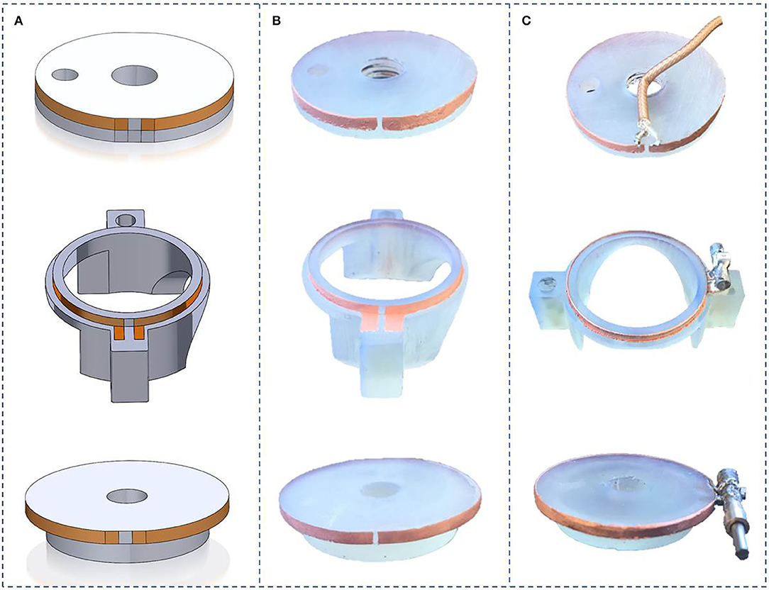
Figure 5. Helmholtz coils realization steps: (A) Solidworks model design, (B) Electroless copper plating of coils on 3D printed parts, (C) Copper thickening by electrolytic Cu plating of coils and soldering of the capacitors.
The whole full 3D printed MRI setup is presented on Figure 6 with, on the left hand side, a zoom on the MR coil integrated within the packaging chamber and, on the right hand side, the whole MRI setup with the mouse positioned for MR-examination. This latter picture illustrates the fact that particular attention has been put on avoiding tape to maintain the mouse which facilitates handling of the probe for in vivo mouse brain imaging. Positioning of the mouse within the coil onto the bed took <10 s. This is particularly fast compared to the time needed to position a mouse in a more conventionally used 32 mm diameter birdcage coil which first requires positioning and taping the mouse in a half pipe bed with the respiratory inserted and then to insert the animal within the MR coil, making it difficult to accurately position the head at the center. Moreover, as the tuning was not changing from one load to another, only initial matching of the MR coil was necessary and took only 1 min. Overall anesthetization and positioning of the animal plus the coil matching lasted <10 min. Finally, the different parts in contact with the animal were easily accessible and the cleaning of the MRI set up after use was fast and easy.
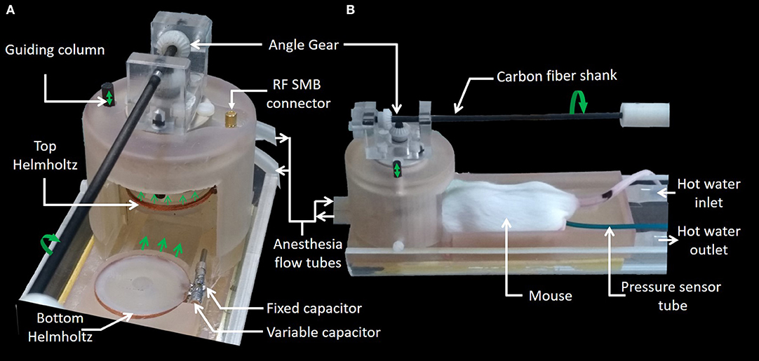
Figure 6. 3D plastronic MRI set-up. (A) MR coil within the packaging chamber. (B) Mouse positioned within the MRI setup and ready for MR examination.
RF Characterization on-Bench
Table 2 summarizes the radiofrequency characterization and deposited-copper thickness measurements. QU of the elements made with copper tape were slightly higher than the ones made with electroless/electrodeposition methods. Surprisingly, QU of the assembled Helmholtz coil 2 (characterized with the VNA through the coupling loop) was higher than for the assembled Helmholtz coil 1. Nevertheless, both Helmholtz coils have similar NF which resulted in equivalent SNR.
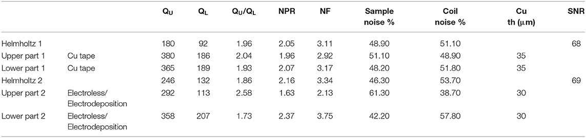
Table 2. Radiofrequency characterization on bench and SNR measurements on homogeneous agarose phantom imaging.
Temperature Mapping of the Heating System
Figure 7 shows the temperature map of the mouse bed when hot water (regulated at 42°C in the bath) flowed through the water circuit. The 3D printed mouse bed had one manufacturing defect (due to the hollow structures) that led to water leakage. This was stopped by gluing a plastic film (yellow rectangle on Figure 7) on the bed that decreased the thermal conductivity at that small surface of the part. Nevertheless, the mouse bed temperature was in the range of about 22–25°C with ambient temperature within the bore of the MRI system at about 10°C. No leakage of water was observed during 3 h of operation.
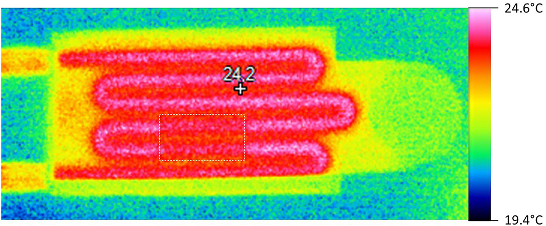
Figure 7. Temperature map of the mouse bed.
Coil Characterization by Imaging
Coil tuning did not change significantly as a function of the load. Once the coil was tuned for one sample, only coil matching was needed to perform MRI acquisition. SNR values measured on agarose phantoms were similar for the coil made with copper tape and with the new metallization process, respectively.
Ex vivo and in vivo High Resolution MRI of Small Samples
Isotropic high spatial resolution images acquired in short acquisition times were compatible with MRI microscopy of small samples. Illustration of ex vivo and in vivo imaging obtained with the MR coil designed with the second metallization process are presented on Figure 8, respectively. A high and uniform SNR was observed over both the whole brain and the whole lamb's kidney. The acquired images show good contrast amongst tissues with different underlying microarchitecture such as cavities, white matter, and gray matter. Many anatomical details within the mouse brain are clearly identifiable in Figures 8A,C, such as the ventricles, the corpus callosum, the caudoputamen, the thalamus, the hippocampus, and the different subregions of the cerebellum. A second example is the lamb's kidney, where the renal pelvis, renal columns, renal pyramids, and renal cortex are easily identified.
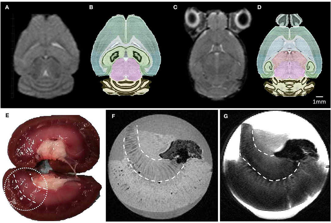
Figure 8. (A–C) Raw MR images of a mouse brain at 2.4 and 3.35 mm depth, respectively. These images were acquired in 15 min using a 2D-RARE sequence with a spatial resolution of 200 × 200 × 500 μm3. (B–D) photos of the corresponding horizontal mouse brain sections obtained from the AGEA online application of the Allen Mouse Brain Atlas. (E) Lamb kidney picture and its corresponding ex vivo MR T1 (F) and T2 (G) weighted images, acquired in 16 and 7 min with spatial resolution of 200 μm3 and 200 × 200 × 500 μm3, respectively. Details of the MR sequence parameters are reported in Table 1.
Discussion
Plastronic: A New Adaptable and Easy Way of Designing and Manufacturing 3D MRI Setups
The smart integration of the Helmholtz coil has been achieved due to the combination of a 3D printed process with a copper metallization technology specially designed for 3D printed polymers. The metallization process used in this work, based on a combination of electroless deposition and electrodeposition, has been validated both by RF characterization on the bench and by imaging. This has resulted in similar RF performance (Quality factor) and SNR as the previous model made with bulk copper tape.
The interest for 3D Plastronics has steadily increased over the past few years and is starting to demonstrate its high potential in the field of sensors and actuators manufacturing [36–38]. Most related works present results on flexible 2D films in order to fit 3D complex shapes, such as human hands, for instance [39]. Moreover, even if particular efforts have been made to embed the electrical components, the severe physical environment constraints related to the use of MRI systems require a shift of paradigm to adapt plastronic processes to MR sensors (dielectric properties, biocompatible materials, cryogenic materials for high sensitivity cryogenic coils, MR compatibility of electrical components and fabrication processes, etc. …). Fortunately, polymers are usually intrinsically compatible with the use in a high magnetic field MRI environment, i.e., in presence of a high static magnetic field. Nevertheless, some polymers can lead to susceptibility artifacts that can be deleterious for the formation of an image. Finally, as demonstrated in this work, it can be advantageous to directly deposit metal on rigid form fitting parts in order to obtain a good filling factor while preventing any motion of the sample. This is particularly relevant in case of MR microscopy.
Recently 3D printing has been used to manufacture custom compatible MRI components for mouse fixation and integration of a dedicated mouse head quadrature coil [40]. One advantage of 3D printing in an MRI lab argued by the authors is to “create individual appliances directly in the lab within reasonably short time periods.” In other words, 3D printing allows for efficient 3D prototyping of MRI setup with smart integration of different parts. Nevertheless, in this reported work the design of the setup was constrained by a commercial coil with already fixed dimensions and hence has limitations in terms of integration of the coil itself. Therefore, to go further, it appears highly beneficial to develop new manufacturing processes of the coil itself, based on an additive manufacturing process compatible with 3D printing processes. To this end the metallization process proposed by J.R. Corea et al. and based on screen-printed flexible MRI coils is a major step forward in the design of MRI coils based on additive manufacturing processes [41]. Nevertheless, this process has few drawbacks: first, this process cannot be applied on small rigid parts, and second, the conductivity of the deposit is relatively low which was not a major problem for designing relatively large surface coils (>8 cm in diameter) for clinical applications that are sample-noise dominated. This latter becomes critical when considering “mid-range” coils made for small sample imaging where noise originates mainly from the coil [10, 11]. Moreover, this technique requires several layer depositions in order to achieve sufficient copper thickness in order to reach a satisfactory quality factor [42]. Finally, as recently demonstrated for very small coils [43], non-planar metallization processes can become advantageous compared to processes that apply bent metal sheets to rigid parts, which can cause metal to break when the radius of curvature is small. In addition, attaching the flexible part can be complex and unreliable.
Benefit for Designing Preclinical MR Coils
In the present work, a single MRI setup has been manufactured that can perform different types of MR experiments without the need to introduce additional devices or change the RF coil. Small in vitro and ex vivo sample imaging as well as mouse brain in vivo imaging have been carried out.
Particular effort has been put into simplifying positioning procedures for small samples and also for animals in the context of in vivo imaging. With a smart integration of the different parts into the MR coil, it has been possible to maintain samples and animals without need of tape in a stable manner (as demonstrated in [40]) so that good quality high spatial resolution images have been obtained on small samples. This type of setup is very close to the 3R approach (Replacement/Reduction/Refinement) that is increasingly recommended in preclinical studies [44].
By synergistically combining 3D printing and 3D metallization processes, we demonstrate a 3D prototyping procedure that allows space to be optimized in the MRI setup. This is particularly important for small-bore preclinical MRI coils where space is limited, especially as other peripherals such as mechanical actuators for magnetic resonance electrography or devices for homoeothermic maintenance of small animals are required and must be smartly integrated in a limited space. In addition, it has been demonstrated that a heating system based on warm water flow can be easily implemented and integrated in a preclinical in vivo MRI setup. Our designs of the MRI setup are available as Supplementary Material to this article.
Limitations of the Manufactured MRI Setup
The MRI setup presented in this paper has several limitations in terms of sensitivity of the MR coil which is related to the noise figure of the coil [34], in terms of homogeneity of the Helmholtz coil which is known to be low compared to a more commonly used birdcage coil, and in terms of integration of tuning and matching devices. Moreover, noise figure values of Table 1 have shown that the manufactured coils are at the limit of noise domains of the sample and the coil. This implies that coil noise was not negligible (QU/QL≈1) which was important to validate the quality of the copper as it was not totally masked by sample noise. Nevertheless, the sensitivity of the coil was limited and could be improved by cooling the copper tracks as demonstrated in Ref. [45] where the coil size and geometry for mouse brain imaging was comparable to the coil shown here. Unfortunately, the available cryogenic solutions developed by MRI vendors for surface coils cannot be easily adapted to volume coils. New manufacturing processes of cryostats could be developed in the future based on plastronic technology. In addition, an important metric for small MRI coil is the RF sensitivity dependence on dielectric losses that could become significant especially when sample losses or conductive losses are very low. In this work the dielectric loss tangent of the resin on which copper was deposited was not measured but could explain the Q variations. On another note the sensitivity of the MRI coil relies strongly on the filling factor which is particularly difficult to achieve for small samples. In the present work particular attention was paid to this effect, but further enhancement of the filling factor could be reached by depositing copper inside the upper part of the Helmholtz coil and by metallizing the sample cup itself. But, whatever the sensitivity of the present coil is, the Helmholtz geometry was used for the sake of simplicity and simplified the optimization step of our metallization process that required multiple test-retests. In a previous study, SNR performance of the present MRI setup made with flexible PTFE copper foils (RT/duroid® 5880LZ Laminates) has been compared to a vendor-provided birdcage coil [46] and provided similar SNR. The same SNR with the actual setup should be expected. A modified Helmholtz coil with four rings could lead to improved homogeneity [47]. Moreover, the photopolymer used in this work might lead to unwanted susceptibility artifacts. These artifacts lead to small, localized perturbations of the static magnetic field that cannot be nulled using the shim fields available on scanner. Nevertheless, as mentioned in [48] this polymer leads to zero NMR signal, and for the MR sequences used here no artifacts have been noticed. To ascertain MR compatibility and artifact free imaging of the photopolymer, MRI properties of the material should be further investigated as in [40].
Finally the matching device developed in this work was very stable and robust, but somewhat bulky. To gain in automatization and compactness of the setup, it could be beneficial to call for noiseless actuators such as piezo actuators for matching and tuning of the MRI coil as demonstrated in [49, 50].
Conclusion and Outlook
The fabricated MRI setup can be used both for in vitro/ex vivo MRI of small samples and for in vivo imaging of a mouse brain. Most components of the device have been 3D printed and directly metallized in order to create the copper tracks of the coil in three dimensions. Two methods for metallization have been tested with similar results. The first is based on the use of copper tape whilst the second is based on a combination of electroless and electrodeposition of copper. The advantage of the second method is that it is reliable and can be applied to different geometries. This metallization process has been validated on the bench and in imaging conditions using a similar coil geometry. This allows addressing of issues related to the design of “mid-range” coils, i.e., fabrication of small complex 3D coils while minimizing coil noise and integrating numerous support and functional parts in a limited space. This MRI setup is perfect to provide a continuum assessment of a mouse brain from in vitro to in vivo stage using MRI. Above all, this MRI setup was developed to validate our manufacturing process and more specifically the metallization process. The precise RF characterization of single loops provides valuable Q ratio data acquired on a simple geometry that can help to validate other manufacturing processes without need of building the entire Helmholtz coil used in the present work. Finally, the manufacturing process used here could be applied to build more sophisticated coil geometries with better SNR and field homogeneity performances.
In the future, this field of research could widely change the design of the MRI coil to a complete system that integrates physiological sensors based on MR compatible optical sensors and/or mechanical actuators based on electroactive ink deposits. This work is the first step toward the full 3D manufacturing of tailor-made multifunctional MRI probes.
Data Availability Statement
All datasets generated for this study are included in the article/Supplementary Material.
Ethics Statement
The animal study was reviewed and approved by CEEA Université Claude Bernard Lyon 1 Ethics Committee n°:55.
Author Contributions
VS, MC, and SL conceptualized the work. TG, VS, PL, and SL carried out device fabrication and characterization. Scanning experiments were designed and performed by SG and SL. TG, VS, PL, MC, and SL discussed the results and commented on the manuscript. All authors contributed to the article and approved the submitted version.
Funding
This work was supported by a grant from the Agence National de la Recherche (Estimate Project N° ANR-18-CE19-0009-01). We are indebted to Romain Delamea for designing and testing the first generation of set-up during his internship, which was financed by the Fondation pour l'Université de Lyon, which support is also acknowledged. It benefited from experimental expertise acquired on the PILoT platform, a member of the France Life Imaging network (ANR-11-INBS-0006) and from the facilities of the platform Plastronique 3D et Packaging Avancé from AMPERE laboratory.
Conflict of Interest
The authors declare that the research was conducted in the absence of any commercial or financial relationships that could be construed as a potential conflict of interest.
Acknowledgments
We would like to thank the financial support provided by Ingénierie@Lyon, member of the Carnot Institutes Network (MetaFab 3D project). We thank Dr. Corinne El Khoueiry for helping in editing the biology text and figure.
Supplementary Material
The Supplementary Material for this article can be found online at: https://www.frontiersin.org/articles/10.3389/fphy.2020.00240/full#supplementary-material
References
1. Chalela JA, Kidwell CS, Nentwich LM, Luby M, Butman JA, Demchuk AM, et al. Magnetic resonance imaging and computed tomography in emergency assessment of patients with suspected acute stroke: a prospective comparison. Lancet. (2007) 369:293–8. doi: 10.1016/S0140-6736(07)60151-2
2. von Knobelsdorff-Brenkenhoff F, Schulz-Menger J. Role of cardiovascular magnetic resonance in the guidelines of the European Society of Cardiology. J Cardiovasc Magn Reson. (2016) 18:6. doi: 10.1186/s12968-016-0225-6
3. Van Beers BE, Daire J-L, Garteiser P. New imaging techniques for liver diseases. J Hepatol. (2015) 62:690–700. doi: 10.1016/j.jhep.2014.10.014
4. Robitaille P-ML. Ultra high field magnetic resonance imaging: a historical perspective. In: Robitaille P-M, Berliner L, editors. Ultra High Field Magnetic Resonance Imaging. Boston, MA: Springer US. (2006). p. 1–17. Available online at: https://doi.org/10.1007/978-0-387-49648-1_1
6. Heidemann RM, Özsarlak Ö, Parizel PM, Michiels J, Kiefer B, Jellus V, et al. A brief review of parallel magnetic resonance imaging. Eur Radiol. (2003) 13:2323–37. doi: 10.1007/s00330-003-1992-7
7. Keil B, Wald LL. Massively parallel MRI detector arrays. J f Magn Reson. (2013) 229:75–89. doi: 10.1016/j.jmr.2013.02.001
8. Pruessmann KP, Weiger M, Scheidegger MB, Boesiger P. SENSE: sensitivity encoding for fast MRI. Magn Reson Med. (1999) 42:952–62. doi: 10.1002/(SICI)1522-2594(199911)42:5<952::AID-MRM16>3.0.CO;2-S
9. Hardy CJ, Giaquinto RO, Piel JE, Rohling KW, Marinelli L, Blezek DJ, et al. 128-Channel body MRI with a flexible high-density receiver-coil array. Journal of magnetic resonance imaging : JMRI. (2008). 28:1219–25. doi: 10.1002/jmri.21463
10. Doty FD, Entzminger G, Kulkarni J, Pamarthy K, Staab JP. Radio frequency coil technology for small-animal MRI. NMR Biomed. (2007) 20:304–25. doi: 10.1002/nbm.1149
11. Darrasse L, Ginefri J-C. Perspectives with cryogenic RF probes in biomedical MRI. Biochimie. (2003) 85:915–37. doi: 10.1016/j.biochi.2003.09.016
12. Franke J, editor. Three-Dimensional Molded Interconnect Devices (3D-MID): Materials, Manufacturing, Assembly and Applications for Injection Molded Circuit Carriers. München: Carl Hanser Verlag GmbH & Co. KG (2014). Available online at: http://www.hanser-elibrary.com/doi/book/10.3139/9781569905524 (accessed December 10, 2019).
13. Hull CW, Lewis CW. Methods and Apparatus for Production of Three-Dimensional Objects by Stereolithography. US4999143A. (1991). Available online at: https://patents.google.com/patent/US4999143A/en (accessed December 10, 2019).
14. Whitesides GM. The origins and the future of microfluidics. Nature. (2006) 442:368–73. doi: 10.1038/nature05058
15. Unnikrishnan D, Kaddour D, Tedjini S. Microstrip transmission lines and antennas on Molded Interconnect Devices materials. In: 2013 13th Mediterranean Microwave Symposium (MMS). Saida: IEEE (2013). p. 1–4. Available online at: http://ieeexplore.ieee.org/document/6663072/ (acceesed January 6, 2020).
16. Sergkei K, Lombard P, Semet V, Allard B, Moguedet M, Cabrera M. The potential of 3D-MID technology for omnidirectional inductive wireless power transfer. In: 2018 13th International Congress Molded Interconnect Devices (MID). (2018). p. 1–6. doi: 10.1109/ICMID.2018.8526962
17. Kamotesov S, Lombard P, Vollaire C, Semet V, Cabrera M, Dahmani R, et al. Modelization and characterization of 2D and 3D mid inductors for multidirectional inductive proximity sensing. In: 2016 12th International Congress Molded Interconnect Devices (MID). (2016). p. 1–6. doi: 10.1109/ICMID.2016.7738936
18. Adams JJ, Duoss EB, Malkowski TF, Motala MJ, Ahn BY, Nuzzo RG, et al. Conformal Printing of Electrically Small Antennas on Three-Dimensional Surfaces. Adv Mater. (2011) 23:1335–40. doi: 10.1002/adma.201003734
19. Schmidt M-P, Oseev A, Engel C, Brose A, Schmidt B, Hirsch S. Flexible free-standing SU-8 microfluidic impedance spectroscopy sensor for 3-D molded interconnect devices application. J Sens Syst. (2016) 5:55–61. doi: 10.5194/jsss-5-55-2016
20. Ait-Ali IF. Développement et intégration de microcapteurs de pH et de température dans des dispositifs microfluidiques polymères. Lyon 1. (2014). Available online at: http://www.theses.fr/2014LYO10003 (accessed October 25, 2016).
21. Seybold J, Kessler U, Fritz K-P, Kück H. Precision micro assembly of optical components on MID and PCB. In: Sarkar P, Iwata T, editors. Advances in Cryptology – ASIACRYPT. (2014). Berlin, Heidelberg: Springer Berlin Heidelberg (2014). p. 30–6. Available online at: http://link.springer.com/10.1007/978-3-662-45586-9_5 (accessed Sepember 26, 2019).
22. Heininger N, Kivikoski M, Lee Y-H. Advanced antennas for mobile phones. In: Proceedings of International Symposium on Antennas, Propagation. Seoul (2005). p. 3–5.
23. Chen JY, Young WB. Two-component injection molding of molded interconnect devices. Advanced Materials Research. (2013). Available online at: https://www.scientific.net/AMR.628.78 (accessed October 4, 2019).
24. Vanfleteren J, Bossuyt F, Plovie B. A new technology for rigid 3D free-form electronics based on the thermoplastic deformation of flat standard PCB type circuits. In: 2016 12th International Congress Molded Interconnect Devices (MID). (2016). p. 1–4. doi: 10.1109/ICMID.2016.7738924
25. Kallmayer C, Schaller F, Löher T, Haberland J, Kayatz F, Schult A. Optimized thermoforming process for conformable electronics. In: 2018 13th International Congress Molded Interconnect Devices (MID). Wurzburg (2018). p. 1–6. doi: 10.1109/ICMID.2018.8526929
26. Cheval K, Coulm J, Gout S, Layouni Y, Lombard P, Leonard D, et al. Progress in the manufacturing of molded interconnected devices by 3d microcontact printing. Advanced Materials Research. (2014). Available online at: https://www.scientific.net/AMR.1038.57 (accessed December 10, 2019).
27. Unnikrishnan D. Mid technology potential for RF passive components and antennas. (2015). Available online at: https://tel.archives-ouvertes.fr/tel-01169922(accessed December 10, 2019).
28. Will K, Schimpf S, Brose A, Fischbach F, Ricke J, Schmidt B, et al. Pre-tuned resonant marker for iMRI using aerosol deposition on polymer catheters. In San Diego, California, USA;. (2010). p. 76251Z. Available online at: http://proceedings.spiedigitallibrary.org/proceeding.aspx?doi=10.1117/12.844243 (accessed September 26, 2019)
29. Goth C, Putzo S, Franke J. Aerosol Jet printing on rapid prototyping materials for fine pitch electronic applications. In: 2011 IEEE 61st Electronic Components and Technology Conference (ECTC). Lake Buena Vista, FL: IEEE; (2011). p. 1211–6. Available online at: http://ieeexplore.ieee.org/document/5898664/ (accessed September 26, 2019).
30. Bidoki SM, Lewis DM, Clark M, Vakorov A, Millner PA, McGorman D. Ink-jet fabrication of electronic components. J Micromech Microeng. (2007) 17:967–74. doi: 10.1088/0960-1317/17/5/017
31. Perelaer J, Abbel R, Wünscher S, Jani R, Lammeren T, van Schubert US. Roll-to-roll compatible sintering of inkjet printed features by photonic and microwave exposure: from non-conductive ink to 40% bulk silver conductivity in less than 15 seconds. Adv Mater. (2012) 24:2620–5. doi: 10.1002/adma.201104417
32. Decorps M, Blondet P, Reutenauer H, Albrand JP, Remy C. An inductively coupled, series-tuned NMR probe. J Magn Res. (1969) (1985) 65:100–9. doi: 10.1016/0022-2364(85)90378-6
33. Ginefri J-C, Durand E, Darrasse L. Quick measurement of nuclear magnetic resonance coil sensitivity with a single-loop probe. Rev Sci Instrum. (1999) 70:4730–1. doi: 10.1063/1.1150142
34. Kumar A, Edelstein WA, Bottomley PA. Noise figure limits for circular loop MR coils. Magn Reson Med. (2009) 61:1201–9. doi: 10.1002/mrm.21948
35. Mispelter J, Lupu M, Briguet A. NMR probeheads for biophysical and biomedical experiments: theoretical principles and practical guidelines. 2nd ed. Imperial College Press (2015). Available online at: http://www.worldscientific.com/worldscibooks/10.1142/p759 (accessed April 29, 2020).
36. Ota H, Emaminejad S, Gao Y, Zhao A, Wu E, Challa S, et al. Application of 3D printing for smart objects with embedded electronic sensors and systems. Adv Mater Technol. (2016) 1:1600013. doi: 10.1002/admt.201600013
37. Xu S, Zhang Y, Jia L, Mathewson KE, Jang K-I, Kim J, et al. Soft microfluidic assemblies of sensors, circuits, and radios for the skin. Science. (2014) 344:70–4. doi: 10.1126/science.1250169
38. Zolfagharian A, Kouzani AZ, Khoo SY, Moghadam AAA, Gibson I, Kaynak A. Evolution of 3D printed soft actuators. Sens Actu APhys. (2016) 250:258–72. doi: 10.1016/j.sna.2016.09.028
39. Zhang B, Sodickson DK, Cloos MA. A high-impedance detector-array glove for magnetic resonance imaging of the hand. Nat Biomed Eng. (2018) 2:570–7. doi: 10.1038/s41551-018-0233-y
40. Herrmann K-H, Gärtner C, Güllmar D, Krämer M, Reichenbach JR. 3D printing of MRI compatible components: Why every MRI research group should have a low-budget 3D printer. Med Eng Phys. (2014) 36:1373–80. doi: 10.1016/j.medengphy.2014.06.008
41. Corea JR, Flynn AM, Lechêne B, Scott G, Reed GD, Shin PJ, et al. Screen-printed flexible MRI receive coils. Nat Commun. (2016) 7:1–7. doi: 10.1038/ncomms10839
42. Corea JR, Lechene PB, Lustig M, Arias AC. Materials and methods for higher performance screen-printed flexible MRI receive coils. Magn Res Med. (2017) 78:775–83. doi: 10.1002/mrm.26399
43. Matsunaga T, Matsuoka Y, Ichimura S, Wei Q, Kuroda K, Kato Z, et al. Multilayered receive coil produced using a non-planar photofabrication process for an intraluminal magnetic resonance imaging. Sens Actu A Phys. (2017) 261:130–9. doi: 10.1016/j.sna.2017.04.021
44. Aske KC, Waugh CA. Expanding the 3R principles. EMBO Rep. (2017) 18:1490–2. doi: 10.15252/embr.201744428
45. Nouls JC, Izenson MG, Greeley HP, Johnson GA. Design of a superconducting volume coil for magnetic resonance microscopy of the mouse brain. J Magn Res. (2008) 191:231–8. doi: 10.1016/j.jmr.2007.12.018
46. Bigot M, Chauveau F, Amaz C, Sinkus R, Beuf O, Lambert SA. The apparent mechanical effect of isolated amyloid-β and α-synuclein aggregates revealed by multi-frequency MRE. NMR Biomed. (2020) 33:e4174. doi: 10.1002/nbm.4174
47. Hoult DI, Deslauriers R. A high-sensitivity, high-B1 homogeneity probe for quantitation of metabolites. Magn Res Med. (1990) 16:411–7. doi: 10.1002/mrm.1910160307
48. Mitsouras D, Lee TC, Liacouras P, Ionita CN, Pietilla T, Maier SE, et al. 3D Printing of MRI-visible phantoms and MR image-guided therapy simulation. Magn Reson Med. (2017) 77:613–22. doi: 10.1002/mrm.26136
49. Keith GA, Rodgers CT, Hess AT, Snyder CJ, Vaughan JT, Robson MD. Automated tuning of an eight-channel cardiac transceive array at 7 tesla using piezoelectric actuators. Magn Reson Med. (2015) 73:2390–7. doi: 10.1002/mrm.25356
50. Li Z, Willoquet G, Guillot G, Hosseinnezhadian S, Jourdain L, Poirier-quinot M, et al. Study of two contact-less tuning principles for small monolithic radiofrequency MRI coils and development of an automated system based on piezoelectric motor. Sens Actu A Phys. (2016) 241:176–89. doi: 10.1016/j.sna.2016.02.008
Keywords: MRI, coils, radiofrequency, 3D print electronics, instrumentation, brain, kidney, preclinic
Citation: Gerges T, Semet V, Lombard P, Gaillard S, Cabrera M and Lambert SA (2020) 3D Plastronics for Smartly Integrated Magnetic Resonance Imaging Coils. Front. Phys. 8:240. doi: 10.3389/fphy.2020.00240
Received: 06 February 2020; Accepted: 02 June 2020;
Published: 28 July 2020.
Edited by:
Ciprian Catana, Massachusetts General Hospital and Harvard Medical School, United StatesReviewed by:
Jason Stockmann, Massachusetts General Hospital and Harvard Medical School, United StatesMichael D. Noseworthy, McMaster University, Canada
Copyright © 2020 Gerges, Semet, Lombard, Gaillard, Cabrera and Lambert. This is an open-access article distributed under the terms of the Creative Commons Attribution License (CC BY). The use, distribution or reproduction in other forums is permitted, provided the original author(s) and the copyright owner(s) are credited and that the original publication in this journal is cited, in accordance with accepted academic practice. No use, distribution or reproduction is permitted which does not comply with these terms.
*Correspondence: Simon Auguste Lambert, c2ltb24ubGFtYmVydCYjeDAwMDQwO3VuaXYtbHlvbjEuZnI=; c2ltb25sYW1iZXJ0MiYjeDAwMDQwO2dtYWlsLmNvbQ==