- Space Plasma, Power and Propulsion Laboratory, Research School of Physics, The Australian National University, Canberra, ACT, Australia
The “cubesat” form factor has been adopted as the defacto standard for a cost effective and modular, nano-satellite platform. Many commercial options exist for nearly all components required to build such satellite; however, there is a limited range of thruster options that suit the power and size restrictions of a cubesat. Based on the prior work on the “Pocket Rocket” electro-thermal capacitively-coupled radiofrequency (RF) plasma thruster operating at 13.56 MHz, a new design is proposed which is based on an inductively-coupled radiofrequency plasma system operating at 40.68 MHz. The new thruster design, including a compact and efficient radiofrequency matching network adjacent to the plasma cavity, is presented, together with the first direct thrust measurements using argon as the propellant with the thruster immersed in vacuum and attached to a calibrated thrust balance. These initial results of the unoptimized first proof of concept indicate an up to 40% instantaneous thrust gain from the plasma compared to the cold gas thrust: typical total thrust at 100 SCCM of argon and 50 W RF power is ~1.1 mN.
1. Introduction
Electric propulsion has been used by satellite operators for station keeping and orbit modification since the 1960's [1]. There are many thruster designs such as gridded ion thrusters and Hall effect thrusters with a proven track record. These systems are complex and are generally designed for larger satellites with the ability to carry large thruster and propellant mass and use high power in the order of kilowatts to achieve their orbit modification goals. In the recent years, there has been a disruption in satellite design by the creation of the cubesat form factor unit with 10 × 10 × 10 cm3 dimensions and up to 1.33 kg of mass [2]. At the time of writing, the online Nanosat database [3] reports over 1,300 nanosats and cubesats that have already been placed in orbit. The majority do not have a propulsion system. There have been many proposed propulsion system designs for this type of satellite [4–11] but most are laboratory designs and very little has been demonstrated or reported in “real” space missions. One reason for this is the many restrictions imposed on the thruster designer by the small satellite form factor with the most important ones being size (~1/3 of the satellite volume and mass) and average power available to the payload (~1 W).
The original Pocket Rocket was proposed in 2012 [12] as a thruster candidate that suits the requirements of a propulsion system of a small satellite. It is an asymmetric, capacitively-coupled, collisional (~1 Torr) RF plasma device and falls under the electrothermal thruster category, together with resistojets and arcjets [13]. The inductive Pocket Rocket (PR) described in this paper is derived from the original capacitive PR, in an attempt to improve its performance and gain further insight into the gas heating and thrust mechanism. In a capacitively coupled plasma system, energy is transferred to the electrons by the electric component of the RF field while in an inductively coupled plasma system it is the magnetic component that serves this role. The switch from a capacitive to an inductive system has potential advantages in both performance by producing an increased ion density [14] and consequently increased propellant heating, and engineering by allowing a simpler, capacitor-only, RF matching network [15].
In order to accommodate the low average power available for the generation of RF, a thruster of the PR type is envisaged to be operated in a low duty cycle. An example of this type of operation is a Hohmann transfer consisting of two, 1-min burns per orbit. In the typical LEO 90-min period orbit, this allows enough time to recharge the batteries between thruster operations. Using this operation scheme and the performance obtained by the inductive PR proof of concept presented in this study, a 2 kg cubesat in a circular 400 km orbit will gain roughly 100 m of altitude per orbit using the thruster at 100 SCCM and 50 W of RF. This can be repeated over a number of orbits in order to achieve the desirable altitude. In terms of power requirement to operate the thruster, two 1-min burns at 50 W RF power need 1.67 Wh of energy. This energy needs to be collected from the solar panels in a period of 90 min (400 km orbit), implying a requirement of approximately 1.11 W of average power, probably closer to 1.5 W if RF amplifier and charging efficiencies are taken into account. This is within the capabilities of a 2-U satellite with extendable solar panels or larger cubesat.
The plasma coupling mode best suited to thrust generation in the capacitive PR is the Gamma mode [16] and not the very low plasma density alpha mode [17, 18]. In the Gamma mode, the electron density increases linearly with RF power and is a result of ion-induced secondary electron emission from the plasma cavity walls surrounded by the RF annulus electrode; in such capacitively coupled thruster, a self-bias generates as a result of the asymmetry between the small powered electrode and the large grounded walls/electrodes. The plasma thrust gain results from two terms, a bulk plasma propellant heating thrust term (resulting from ion-neutral charge exchange collisions) which immediately takes place at turn on (first 100 ms) and a wall propellant heating thrust term (resistojet effect) which increases with burn time as a result of ion bombardment of the radial plasma cavity walls. These two thrust terms have never been directly demonstrated and quantified experimentally. They have been indirectly deduced via gas temperature measurements [19]. Due to the small aperture area and large neutral density compared to the ion density, any thrust term from ion acceleration would remain small.
In terms of power coupling to the plasma, the inductive PR resembles the well documented low pressure (~ mTorr) Helicon/inductive plasma sources and thrusters [20] which exhibit a capacitive coupling mode at low RF power and an inductive mode at higher power. For the mm size (diameter) and cm size (length) inductive PR it is necessary to operate at pressures around a few Torr to couple the plasma and the capacitive-inductive transition occurs at about 20 W. The present study focuses on the inductive mode obtained in the 20 W to 50 W power range. In terms of thrust generation, the main source of thrust expected from the inductive PR should be similar to that of the capacitive PR due to the plasma source scaling, operating pressure range and input power range or a few tens of watts. Basic thrust measurements have been previously performed for a larger inductively coupled thruster (i.e., 5 cm diameter) operating with input power ranges of a few hundred watts [21, 22] and at operating pressures of a few mTorr. It was shown that a typical power input of 100 W would result in about 1 mN of thrust, the maximum electron pressure in the plasma cavity (experimentally measured and also the result of a basic global model including particle balance and power balance, as described in chapter 10 of [14]) is converted into ion momentum along the expanding plasma as predicted by Fruchtman [23]. Fruchtman [24] also discussed the complexity of thrust imparted by low pressure and high pressure expanding plasma sources. For capacitive PR, the basic understanding of the plasma-generated thrust increase at 13.56 MHz from the cold gas thrust has been validated using CFD Ace+ [25] and HEMP fluid-plasma transient simulations [21]. In the present study, we demonstrate direct thrust measurement of a mm size inductively coupled plasma source using a vacuum compatible miniaturized impedance matching system at 40.68 MHz. Since this is simply a proof of concept, it is premature to directly compare with other technologies. Instead we provide additional references cases of a cold gas system and of a filament heated resistojet system and some comparative discussion with larger low pressure inductively coupled thruster.
2. Physical Description
2.1. First Experimental Configuration
Two experimental configurations are used to develop and characterize the inductive PR: a first configuration where the prototype is directly mounted onto a small size vacuum chamber (“Chi-Kung”) and a second configuration where the prototype is immersed in a much larger vacuum chamber (“Wombat”). A photo of the inductive PR mounted onto the previously described Chi-Kung vacuum chamber [26] is shown in Figure 1 and a simplified schematic is shown in Figure 2. The inductive PR consists of a plenum (a grounded cylindrical cavity into which gas is introduced) contiguously connected to a 5.5 mm outer diameter and 4.0 mm inner diameter ceramic (alumina) tube which forms the plasma cavity. The length of the alumina tube is approximately 6 cm. The ceramic tube is surrounded by a multiple turn RF loop antenna. The plenum (left exit of the plasma cavity on Figure 1) is made with aluminum and has a cylindrical shape with 25 mm diameter and 15 mm depth resulting in ~7 cm3 of volume. Viton o-rings are used to ensure a good vacuum seal between the ceramic and the aluminum. The o-rings are compressed with aluminum clamps which are tightened in place with screws. The exhaust end of the ceramic tube is connected via an appropriate aluminum flange to the 30 cm long 15 cm diameter pyrex tube of the Chi-Kung vacuum system, simulating the vacuum conditions of space.
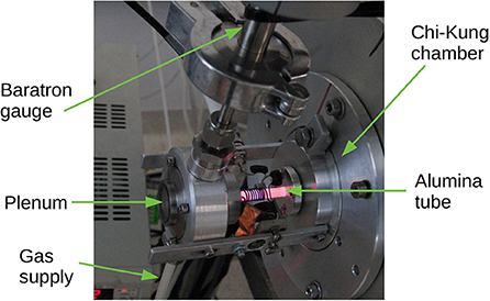
Figure 1. Photo of the inductive PR (center left) connected to the Chi-Kung vacuum chamber (right). The baratron vacuum gauge is connected to the top of the plenum and the gas supply to the bottom. The inductive PR is operating with argon at 100 SCCM and 30 W of RF power at 40.68 MHz. Part of the RF matching network is also visible, in this instance consisting of silver mica capacitors and a variable capacitor which was used for fine tuning.
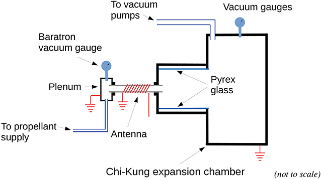
Figure 2. A simplified sketch of the inductive PR, shown here connected to the Chi-Kung expansion chamber at lower pressure (as seen in Figure 1). The Pyrex glass inside the chamber is part of a different experiment also run on Chi-Kung and bears no significance in the experiments described in this paper.
Gas is injected to the plenum via 1/4″ flexible hose (Figure 1). For the Chi-Kung testing configuration, an MKS 626B Baratron pressure sensor is connected to the plenum via a short, rigid 1/4″ pipe and KF25 vacuum fittings in order to provide pressure measurements with the plasma “off” or “on,” a parameter previously identified as a measure of neutral gas heating [16, 27]. The gas supply consists of a centrally located argon cylinder at high pressure, a ~60 PSI regulator and an MKS Type 247 display and MKS Mass-Flo gas flow controller which allows an accurate selection of gas flow up to 140 SCCM. The plenum pressure varies with the cold gas flow rate from a fraction of a Torr at a few SCCM of gas flow to ~3 Torr, at 140 SCCM. The Chi-Kung expansion chamber is pumped by a rotary vacuum pump and a secondary turbomolecular pump. The vacuum base pressure in the chamber is typically ~8 × 10⁻⁴ Torr when the gas supply is off and rises up to ~10−2 Torr with the gas supply at the maximum setting of 140 SCCM. The pressure in the plenum and plasma cavity is greater by a factor of >100 to that in the vacuum chamber, ensuring the system is operating in choked flow conditions [25, 28]. This is checked by confirming that the plenum pressure is not affected by the downstream pressure.
A 10-turn, 1 mm diameter, ~15 mm long along the thruster main axis, copper wire inductor forming the RF antenna is wound on the ceramic tube as seen in Figure 2. It is not in contact with the plasma making this system an electrodeless thruster. The plenum end of the inductor is grounded and the exhaust end is connected to the RF matching circuit (described in detail in section RF Circuit Description). The matching circuit matches the inductive load formed by the antenna and the plasma system to 50 Ω to allow easy connection via any length 50 Ω coaxial cable to a laboratory grade wideband RF amplifier (Mini Circuits ZHL-100W-GAN+). The amplifier is driven by a 40.68 MHz sine wave signal from a Keysight 33600A arbitrary waveform generator which is used to control the output power and, when pulsed, the duty cycle of the RF supplied to the thruster (a feature not used in the present study). The RF circuit also includes a cross-needle Daiwa CN-801 SWR meter which is used to confirm power and matching quality. A high-flow cooling fan can be used to cool the inductor to ensure the Viton o-rings do not overheat when operated at high power and for long duration. With the cooling supplied from the external fan, the prototype can run continuously at 40 W reaching a maximum temperature near the center of the coil not exceeding 200°C. In these conditions, thermal equilibrium is achieved within a minute of RF being switched on. The inductive PR Chi-Kung setup can be used not only to test and optimize the RF circuitry but also the RF power transfer into the plasma by allowing plenum pressure measurements.
2.2. Second Experimental Configuration
The main aim of this study is to demonstrate thrust gain from gas heating during plasma operation with the newly designed 40.68 MHz compact impedance matching system. To this effect a second configuration is used where the inductive PR with matching network is attached to a thrust balance and fully immersed within the previously described, larger Wombat vacuum chamber [15, 29]. Major components of this assembly are shown in Figure 3; a photo of the prototype operating in the Wombat chamber is shown in Figure 4. In this set up the RF antenna is located at a distance of ~8 mm from the exhaust plane of the plasma cavity. The length of the ceramic tube is reduced to a length of ~4 cm compared to the Chi-Kung setup. Similar measurements have been conducted in this chamber in the past for the capacitive PR mounted on the large, four-arm, thrust balance [29]. Here essential improvements to the thrust measurement procedure have been carried out as follows: the propellant is supplied via a flexible PTFE hose with an outer diameter of 1.5 mm and inner diameter of 0.8 mm, and RF power is supplied via a flexible RF cable (RG316). Both lines are attached to suitable vacuum feed through connectors to allow connection with the gas controller (Alicat scientific) and RF power supply (Oregon Physics VRG1000A), both located outside the chamber. Care has been taken to ensure both gas line and RF cable are mounted in a way that is not influencing the measurements. The lack of influence in the displacement from the gas line and RF cable was confirmed by the repeatability of the results in a large number of cold gas operations and by the observation that there is no displacement change when RF was switched on with no gas. When the thruster operates, either in cold gas or plasma mode, the balance moves in reaction to the applied force and the displacement D is measured with a previously described laser-sensor system [29]. This system is based on a laser triangulation displacement sensor (ILD1700) and has a resolution of 0.1 μm. The thrust to displacement calibration factor is 0.044 mN/μm and is obtained by using a calibration system consisting of a set of well known weights on a string connected via a pulley to the balance. The application of the weights is controlled by a stepper motor, installed in the chamber. Vacuum in the chamber is produced by three pumps: a Neovac SS120W roughing pump achieves ~ 10−2 Torr with no gas flow and a large Varian V1800A turbomolecular pump with a pumping speed of 1600 l/s (N2) improves the vacuum to ~10−6 Torr. A cryopump is also available but was not used in these measurements.
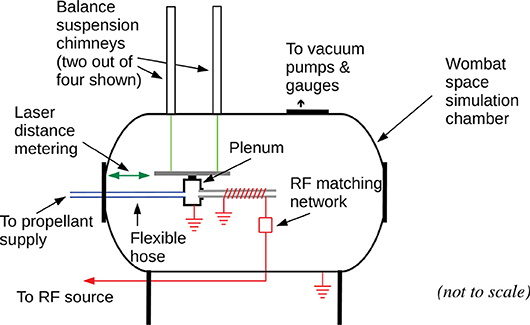
Figure 3. A simplified sketch of the inductive PR, shown here installed in the Wombat vacuum chamber equipped with a thrust balance.
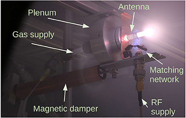
Figure 4. Photo of the inductive PR mounted on the thrust balance and shown operating inside the Wombat chamber. The magnetic damper consisting of a copper tube attached to the chamber and a set of permanent magnets attached to the thruster can be seen below the thruster, to the left hand side. The RF matching network can also be seen, in this instance consisting of fixed value silver mica capacitors only.
To avoid putting the balance in an undamped oscillation every time there is a thrust change or external stimulus (mechanical vibration) and to quickly return to a baseline position, a custom-made magnetic damper is installed. The damper, seen in Figure 4, uses permanent magnets attached to the balance and inserted into a copper tube which is attached to the chamber. The eddy currents produced in the copper by the movement of the magnets result in a force opposing the movement and as a result have a damping effect. The time constant of this damping mechanism is in the order of a few seconds. This damping effect is further augmented by filtering done at the raw data level resulting in an improved sensitivity system. The thrust measurement campaign aims at assessing the cold gas thrust and the thrust gain when the plasma is turned on for varying gas flow rate and varying RF power. There is presently no cooling system and plasma runs (burns) are kept to a minute or less to avoid overheating damage to the Viton o-ring. No thermal drift of the balance was observed due to the short plasma burns.
2.3. RF Circuit Description
2.3.1. Frequency Selection of 40.68 MHz
The selection of frequency of operation for the inductive PR is based on two distinct requirements. The first one is the requirement to operate on a frequency that is not likely to cause interference to any other user of the radio spectrum. This requirement must be satisfied for all areas the satellite will be flying over, as determined by its orbit. The second one is to select a frequency which provides optimal performance of the thruster and is compatible with the cubesat architecture restrictions stated earlier in this paper.
To facilitate the operation of RF systems of Industrial, Scientific and Medical (ISM) nature (such as the cubesat thruster), the International Telecommunications Union (ITU) has determined a number of bands which are agreed by all member states to be used for such applications in a global scale. These bands are listed in the 2016 edition of the ITU Radio Regulations document (footnote 5.150) and are 13.56 MHz, 27.12 MHz and 40.68 MHz in the HF/VHF part of the spectrum, followed by 2.4 GHz, 5.8 GHz, and 24 GHz in the microwave part of the spectrum. There are other bands between VHF and microwaves allocated for similar applications by local administrations in many countries, however they do not enjoy the same global recognition as the ISM bands do. The technology to build suitable RF sources for the three lower ISM bands has been demonstrated and includes novel amplifier designs such as the Class-E [30]. Class-E amplifiers for the HF/VHF part of the spectrum have been constructed with 90% efficiency or better [31, 32]. While the inductive PR thruster could in theory be designed to be powered by a microwave source, the strict restrictions of the cubesat platform make this choice a more challenging one due to generally lower efficiency achievable on these frequencies. A typical efficiency value of high-efficiency RF sources for 2.4 GHz systems is ~50% which indicates not only a higher input power requirement for a given RF output power, but also an exacerbated semiconductor heat dissipation problem.
In order to select one of the three lower ISM bands, it is important to explore the impedance characteristics of an inductively coupled plasma device like the inductive PR. The impedance Z at the antenna with the plasma ignited can be represented as
where Rp is the resistance component and ωL is the inductive reactance of the antenna. The angular frequency, ω, relates to the RF frequency, f, according to the formula ω = 2πf. The inductance, L, is mostly dependent on the antenna length, diameter and number of turns. The Rp component of the impedance is due to the plasma absorbing energy and is not dependent on frequency. The power deposited in the plasma is where I is the antenna current. For a given current (or plasma deposited power), the voltage across the antenna Vant is determined by the reactance and not the resistance as, for the typical inductive PR operating conditions, R ≪ ωL and is Vant ≈ ωLI. The higher voltage offered by the higher frequency is an important advantage to consider in the thruster design as it facilitates a quicker and more predictable striking of the plasma. Rl represents the loss component and is mostly due to the skin effect influenced AC resistance of the copper wire. In the case of the inductive PR, Rl ≪ Rp for all three ISM bands. Typical values at room temperature for the highest frequency of 40.68 MHz and copper conductors are Rl = ~0.1 Ω and Rp = ~3.1 Ω. Rl increases with frequency but Rl ≪ Rp still holds at the expected operating frequencies of the prototype. The losses can be further improved by using silver plated conductors instead of copper. Based on the above the frequency of operation chosen for the present development of the prototype is the ISM band of 40.68 MHz, a change from the 13.56 MHz previously used for the capacitive PR [12].
2.3.2. Impedance Matching Network
The plasma producing inductor appears as an impedance of ~3.2 + j56 Ω (at 40.68 MHz), obtained by direct voltage and current measurements and calculations based on the matching network component values. Small variations in this impedance may be observed and are due to parasitic impedances in the space immediately around the inductor as well as the gas flow rate and copper temperature, with the last two affecting the real part of the impedance. There are multiple circuits that will match the ignited plasma impedance to 50 Ω (the output impedance of commercial RF sources used in the laboratory) consisting of inductors and capacitors. In general, inductors introduce added losses due to ohmic heating, can be affected by objects in their surrounding and take more space. While innovative solutions for manufacturing inductors have been proposed [33], a capacitor-only matching network is preferred if possible [15]. The two simplest capacitor-only networks are shown in Figure 5, together with the Smith chart solutions.
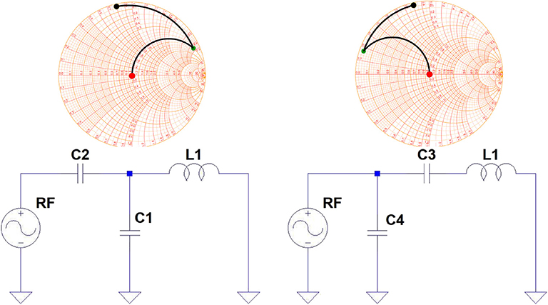
Figure 5. Two capacitor-only matching networks that are suitable for the inductive PR impedance matching system. L1 indicates the plasma antenna, shown in Figures 1, 2. The Smith charts on top of each circuit show the intermediate steps in the impedance transformation.
Out of these two matching circuits, the one using C1/C2 was selected because it results in lower value capacitors which are generally easier to obtain with very low or zero temperature coefficient (C0G/NP0 types). In the prototype C1 is implemented with a fixed capacitor network resulting in a total capacitance of ~53 pF and C2 is a fixed ~18 pF capacitor. Another advantage of the C1/C2 matching circuit over the C3/C4 one is avoiding the relatively high current that will flow on C4.
Before plasma ignition, the matching network does not provide a good match to 50 Ω due to the lack of the plasma resistance. In this case, circuit simulations show that there is a higher current I flowing on the inductor, which results in a higher voltage V across it. This is beneficial for the successful ignition of the plasma. If the RF power is decreased below the design range of 20 W to 50 W, the plasma switches to a capacitive mode. This is visually observed from the brightness of the plasma being asymmetric and much brighter at the “hot” (not grounded) end of the inductor. If the power is increased to the design range, the discharge becomes inductively coupled and the brightest spot moves to the center of the coil. The voltage across the inductor is ~250Vpeak for 40 W RF power.
It is convenient to have a 50 Ω system in the laboratory. However, this is not a requirement for the final design that will operate on a cubesat. In this case, the amplifier can be designed with an output impedance of 3.2 Ω and the matching network can be reduced to a single capacitor with enough capacitive reactance to tune out the +j56 Ω inductive reactance of the load. The impedance was found not to vary significantly when the thruster is operated within its design range of power (20 W to 50 W) and argon gas flow (20 SCCM to 100 SCCM) At 40.68 MHz, this results in a ~70 pF capacitor. Such direct impedance match has been successfully demonstrated for capacitive PR [31].
3. Experimental Results
3.1. Direct Thrust Measurements: Cold Gas Thrust
In an electrothermal RF plasma thruster the total thrust (FT) consists of two main components, the cold gas thrust (Fcg) and the plasma thrust (Fp):
Figure 6 shows the raw displacement D (from the thrust balance laser-sensor system) over time in cold gas operation for increasing argon flow rate (0 SCCM to 200 SCCM in 20 SCCM incremental steps) and decreasing flow rate (200 SCCM to 0 SCCM in 50 SCCM incremental steps). Each step is ~20 s long. The data sampling rate is 312.5 Hz with a moving average of 256 applied. The data is then reduced by taking the mean every 16 measurements. The result is a measurement clear of frequencies >1 Hz which are most likely noise. This measurement was repeated 4 times to obtain the Fcg results shown by green crosses on Figure 7. Plenum pressure Pplenum, shown in the figure as blue stars, varies from 0 Torr to ~3 Torr when the argon flow rate increases from 0 SCCM to 200 SCCM.
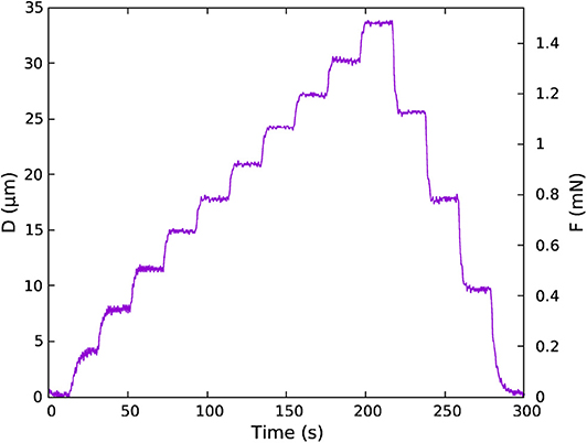
Figure 6. Raw data from thrust balance showing balance displacement D over time. In this sequence, the thruster was operated with cold gas starting at 0 to 200 SCCM in steps of 20 SCCM, then return back to 0 SCCM in steps of 50 SCCM. Each step lasts for 20 s. The data sampling rate is 312.5 Hz with a moving average of 256 applied. It is then reduced by taking the mean of every 16 measurements. The basic calibration is measured to be approximately 0.044 mN/μm.
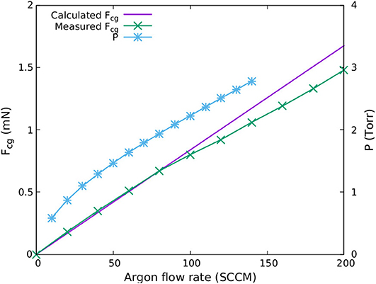
Figure 7. Calculated cold gas thrust Fcg (solid purple line), measured thrust Fcg (green crosses) in the Wombat chamber (Figure 3) and plenum pressure Pplenum (blue stars) measured in the Chi-Kung chamber (Figure 2), vs. argon flow rate.
On first approximation, neglecting the neutral gas pressure term, the axial thrust force generated by the cold gas can be approximated for an isentropic, choked flow (Mach number M = 1) regime by the momentum term [27]
where ṁ is the argon mass flow rate and is the argon gas sound speed (Ts is the static temperature at the exit of the tube, R = 8.314 J.mol−1K−1 is the universal gas constant, γAr is the specific heat capacity ratio for argon and mAr is the argon molar mass). At Ttotal ~ 300 K, Ts given by the formula is about 225 K, cs is about 279.2 m/s and the calculated Fcgcalc shown by the purple solid line on Figure 7 increases up to ~1.7 mN for 200 SCCM of argon. Agreement between Fcgcalc and Fcgmeas is very good at flow rates below ~80 SCCM giving confidence that the experimental system is appropriate. The measured thrust Fcgmeas is somewhat lower than the calculated thrust at high flow which indicates that some unaccounted loss is occurring in the system. This loss is likely due to the boundary layer friction force acting upon the inner wall of the ceramic tube, as described in detail by Ho et al. [25].
3.2. Direct Thrust Measurements: Plasma Thrust
The next step in the characterization of the inductive PR is the measurement of the thrust increase Fp when the plasma is ignited (as shown in Figure 4). For the thrust measurement procedure, the prototype is fed with a constant gas flow rate, the balance is allowed a few seconds to settle and the RF is subsequently switched on. A typical measurement of the balance displacement D at plasma ignition and thereafter is shown by a solid purple line in Figure 8. D exhibits a rapid increase due to the volumetric gas heating directly by the RF power, followed by a slower increase due to the ceramic wall heating up via ion bombardment and exchanging heat with the propellant as described in detail in Greig et al. [19]. In this figure the effect of the magnetic damper can be observed with the ~2 s period oscillations in the displacement being damped effectively within a few seconds.
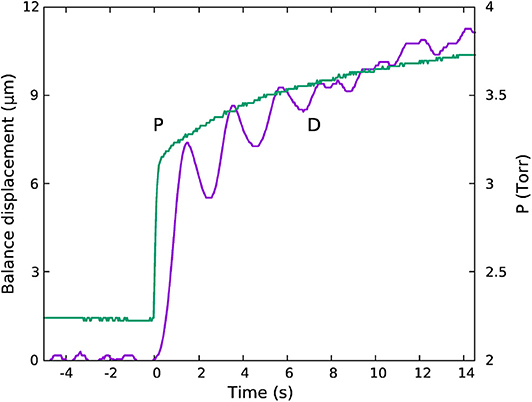
Figure 8. Balance displacement D (solid purple line) measured in the Wombat chamber and plenum pressure Pplenum (solid green line) measured in the Chi-Kung chamber, over time for 100 SCCM of argon and 50 W of RF. The RF is switched on at t = 0 s. The RF current flowing on the antenna when the RF is switched on is ~4 A RMS.
A useful qualitative diagnostic indicative of thrust from the plasma is the plenum pressure Pplenum, measured with the inductive PR mounted onto the Chi-Kung chamber (first configuration), and shown by the solid green line on Figure 8 for the same flow rate and RF power. The displacement and plenum pressure plots are synchronized to the time the RF is switched on (t = 0s). The variation in Pplenum vs. time strongly matches that of the balance displacement. The thrust increase due to the wall heating up can be compared to the resistojet thruster principle and it is found to be a function of gas flow rate, RF power and heat dissipation mechanism. For the present study we only focus on plasma thrust gain at plasma ignition vs. the two main parameters, RF power and argon gas flow rate.
The effect of RF power in the plasma thrust (Fp) for a fixed 100 SCCM argon flow rate is presented in Figure 9. The data points in this plot are the average of 8 measurements of 20 s burns for each power and the error bars reflect the distribution of these measurements. The reported thrust does not include the slow resistojet increase which can be seen in Figure 8. Fp increases quasi-linearly from 0.14 mN at 20 W to 0.3 mN at 50 W. Since the pressure is of the order of one Torr in the plasma cavity (same as capacitive PR), it is expected that the source of thrust will be mostly from heated neutrals [16]. Previous thrust measurements have been reported for inductive RF sources [21]: for a 6.5 cm-diameter, 9.5 cm-long plasma cavity in which the operating pressure was of the order of a mTorr (~55 SCCM of argon), the source of thrust was shown to be mostly a result of the maximum electron pressure converted into ion momentum and about 0.5 mN at 100 W.
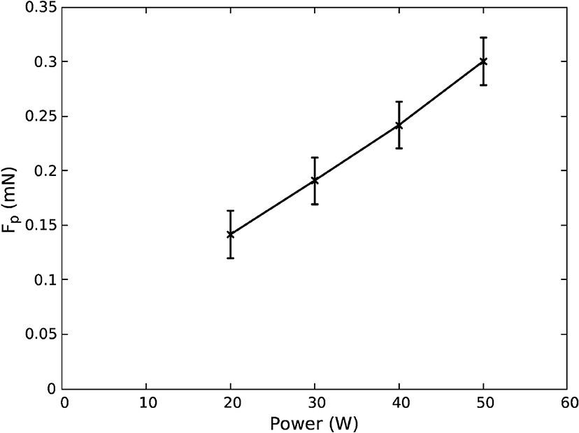
Figure 9. Plasma thrust Fp vs. absorbed RF power for fixed 100 SCCM argon flow (solid line, crosses). The reported thrust in this plot does not include the cold gas Fcg component which is ~0.8 mN, as seen in Figure 7.
It is of interest to carry out a basic estimate of the thrust from ions for the mm scale inductive PR inductive RF source for comparison. This was done using a global plasma model (comprising a particle balance and power balance) described in detail by Lieberman and Lichtenberg [14] and previously applied to low pressure RF sources [20] to determine a maximum electron density subsequently used in a plasma thrust model described in detail by Fruchtman [23], and successfully applied to inductively coupled RF thrusters [21, 34]. In the latter, ion-neutral collisions are ignored and the thrust from accelerated ions is given by the maximum electron pressure within the plasma source region, Fion = qneATe, where q is the electron charge magnitude, ne is the maximum radially averaged density within the source region, A is the cross-sectional area of the source tube, and Te is the electron temperature. A thrust reduction factor of 0.6 [21] to 0.82 [34] to account for the radial density profile in a cylindrical source is typically used.
A particle balance for a cylindrical plasma which consists in equating the total surface particle loss to the total ionization [14, 20] was initially carried out to determine the electron temperature (assuming a Maxwellian distribution) and the ion Bohm velocity: ignoring the presence of the plenum cavity and using a plasma cavity radius of 2 mm and length of 15 mm, approximately corresponding to the antenna footprint shown in Figure 4, and a mid-cavity pressure of 1.1 Torr corresponding to half the plenum pressure measured for 100 SCCM gas flow (Figure 8), the electron temperature is about 2.0 eV and the Bohm velocity m/s. The input gas temperature was assumed to be 300 K in first approximation. Such procedure was also carried out in the capacitive PR as described in Charles and Boswell [12] yielding similar output due to the similar geometry and operating gas pressure. These capacitive PR results were later confirmed with direct electrostatic probe measurements and computer simulations [28, 35].
Based on the derivation of the electron temperature with the particle balance, a power balance was subsequently used to estimate the maximum plasma density (nemax = nimax) as described in Lafleur et al. [21], Lieberman and Lichtenberg [14], Lieberman et al. [20] and determine the thrust from the electron pressure neTe (which is converted into axial ion momentum as previously detailed in Lafleur et al. [21] and Fruchtman [23], here a thrust factor of 0.6 is used for the radially averaged plasma density, i.e., ne = 0.6nemax). An approximate power input reduction factor of 0.9 was used to account for the electrical power transfer inefficiency of the matching circuit. This model yields a thrust from ions of 25 μN at 20 W to 63 μN at 50 W of RF power which is between 18% (at 20 W) and 21% (at 50 W) of the measured values. These values are significantly lower than the respective measured thrust values shown in Figure 9 (140 μN and 300 μN for 20 W and 50 W, respectively). This is an indication that like its predecessor the capacitive PR, the inductive PR behaves like an electrothermal thruster (thrust gain from heated neutrals) rather than a plasma or ion thruster when operated in the configuration of geometry, power and gas flow rate described in this paper.
Having confirmed that the main thrust generation mechanism is neutral gas heating (rapid increase reported in Figure 9 due to the volumetric gas heating directly by the RF power, followed by a slower increase due to the ceramic wall heating up via ion bombardment and shown in Figure 8, the variation in thrust from the ions was investigated as a function of the gas temperature since we initially assumed a gas temperature of 300 K. Assuming a gas temperature increase of a factor of 2 from 300 K to 600 K for 20 W power input gives an electron temperature of 2.3 eV and an ion thrust of 19 μN (down from 25 μN). This simple estimate shows the interplay between thrust generation from heating neutrals and accelerated ions. Global models provide no spatial information and should be complemented by future dedicated computer simulations for further investigation.
Figure 10 shows the effect in Fp of flow rate change when keeping the RF power constant. The knee point seen at about 60 SCCM in this plot is likely to be related to the physical dimensions of the tube and will be the topic of future work. In summary, the comparison between Fp at ignition for this unoptimized thruster and Fcg shows a total thrust increase of up to 40%.
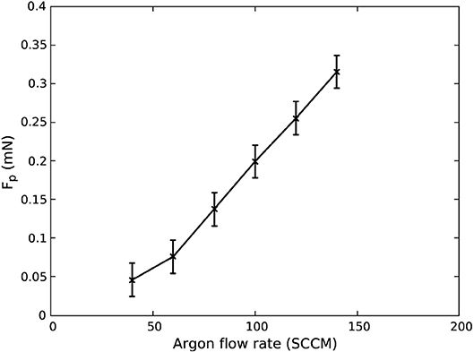
Figure 10. Plasma thrust Fp vs. flow rate for fixed 30 W RF power. The reported thrust in this plot is the thrust due to the RF and does not include the cold gas component.
The thrust reported so far does not include the slow increase of thrust over time shown in Figure 8 which is attributed to the ceramic wall heating. This increase however has an important role in the overall performance of the system. To understand better this effect, a simple resistojet experiment was performed using a constant 100 SCCM argon flow into a same dimensions plenum and ceramic tube system. In this experiment, the RF antenna was replaced by a tungsten wire which is placed inside the tube and was heated up to glowing temperatures by 20 W of DC power. The heating element had a diameter of 2 mm and length of ~1 cm and was placed at a distance L from the exhaust end of the tube. Thrust measurements were made on the Wombat balance by setting up a constant 100 SCCM flow, then turning on the heating element for 20 s and recording the thrust at the end of that period. At L = 0 mm, the thrust gain over the cold gas thrust, FT/Fcg, was 1.99 dropping to 1.65 at L = 5 mm, 1.34 at L = 10 mm, 1.22 at L = 15 mm and 1.08 at L = 20 mm. The gradual decrease in thrust can be attributed to the cooling down of the gas while traversing the final length of the tube which did not have enough time to reach a temperature equilibrium. An attempt was made to shift the RF antenna of the inductive pocket rocket closer to the exhaust end of the tube to confirm this observation with an RF plasma but the RF matching was affected possibly due to the pressure change near the exhaust end and was impossible to get reliable data. This observation is going to be an important focus on future optimizations of this thruster.
Another point of interest to future optimizations is the formation of parasitic plasma outside the ceramic tube. This is due to the pressure in the vacuum chamber increasing from 10−6 Torr to ~10−3 Torr when the thruster is operational which resulted in enough gas density to ignite and sustain a weak plasma outside the ceramic tube. The effect of this is that a percentage of the injected power is lost to that parasitic plasma which contributes to the lower performance of the thruster. In space, this is less likely to be a problem however it is possible to mitigate it the impact by increasing the vacuum pumping speed and protecting the area directly over the antenna by some inert material to discourage the formation of plasma.
4. Conclusions
The present study demonstrates total thrust gain at plasma ignition in a small size inductively coupled Pocket Rocket, operating as an electrothermal plasma thruster. A small foot print impedance matching network operating at 40.68 MHz and mounted directly onto the plasma cavity allows reliable measurements of direct thrust with inductive PR immersed in vacuum and attached to an optimized thrust balance. A magnetic damper facilitates the measurement procedure by limiting thermal effects during plasma burns which allows reliable and repeatable measurements. The measured thrust is found to be comparable with the predecessor capacitive PR, however, absolute comparisons are not easy to make due to the unknown losses in the matching network of the capacitive PR vs. and the differently configured thruster balance used for those early experiments. The direct thrust measurements of the inductive PR have confirmed the production of thrust and have highlighted a couple of areas of improvement which will be considered in future work. Based on the reported results, future studies are justified and are expected to incrementally improve the performance of the presented proof of concept.
Data Availability Statement
All datasets generated for this study are included in the article/supplementary material.
Author Contributions
This work presented in this paper is DT's Ph.D. student work and has been supervised by CC and RB.
Conflict of Interest
The authors declare that the research was conducted in the absence of any commercial or financial relationships that could be construed as a potential conflict of interest.
References
1. Goebel DM, Katz I. Fundamentals of Electric Propulsion: Ion and Hall Thrusters. Hoboken, NJ: John Wiley & Sons, Inc. (2008). doi: 10.1002/9780470436448
2. California Polytechnic State University. Cubesat Design Specification rev. 13 (2014). Available online at: http://www.cubesat.org/s/cds_rev13_final2.pdf
3. Kulu E. Nanosat Database. (2019). Available online at: https://www.nanosats.eu
4. NASA. State of the Art of Small Spacecraft Technology. Hanover, MD: NASA (2018). Available online at: https://sst-soa.arc.nasa.gov/
5. Pascoa JC, Teixeira O, Filipe G. “A review of propulsion systems for cubesats,” in: ASME International Mechanical Engineering Congress and Exposition, Proceedings (IMECE). Pittsburgh, PA (2018).
6. Lemmer K. Propulsion for CubeSats. J Acta Astron. (2017) 134:232–43. doi: 10.1016/j.actaastro.2017.01.048
7. Keidar M, Zhuang T, Shashurin A, Teel G, Chiu D, Lukas J, et al. Electric propulsion for small satellites. Plasma Phys Control Fusion. (2015) 57:014005. doi: 10.1088/0741-3335/57/1/014005
8. Mueller J, Hofer R, Ziemer J. Survey of propulsion technologies applicable to cubesats. In: 57th JANNAF Propulsion Meeting. Pasadena, CA (2010).
9. Tummala AR, Dutta A. An Overview of Cube-Satellite Propulsion Technologies and Trends. Aerospace (2017). Available online at: http://www.mdpi.com/2226-4310/4/4/58
10. Leomanni M, Garulli A, Giannitrapani A, Scortecci F. Propulsion options for very low Earth orbit microsatellites. Acta Astronaut. (2017) 133:444–54. doi: 10.1016/j.actaastro.2016.11.001
11. Scharlemann C, Tajmar M, Buldrini N, Krejci D, Seifert B. Propulsion for nanosatellites. In: 32nd International Electric Propulsion Conference. Wiesbaden (2011).
12. Charles C, Boswell RW. Measurement and modelling of a radiofrequency micro-thruster. Plasma Sources Sci Technol. (2012) 21:022002. doi: 10.1088/0963-0252/21/2/022002
13. Charles C. Plasmas for spacecraft propulsion. J Phys D Appl Phys. (2009) 42:163001. doi: 10.1088/0022-3727/42/16/163001
14. Lieberman MA, Lichtenberg AJ, . Principles of Plasma Discharges and Materials Processing. 2nd ed. Hoboken, NJ: Wiley (2005). doi: 10.1002/0471724254
15. Charles C, Boswell RW, Bish A. Variable frequency matching to a radiofrequency source immersed in vacuum. J Phys D Appl Phys. (2013) 46:365203. doi: 10.1088/0022-3727/46/36/365203
16. Ho TS, Charles C, Boswell R. Neutral gas heating and ion transport in a constricted plasma flow. Phys Plasmas. (2017) 24:084501. doi: 10.1063/1.4996014
17. Doyle SJ. Electron, Ion and Neutral Heating in Hollow Cathode Plasma Thrusters. York: University of York (2019).
18. Ho TS, Charles C, Boswell R. Redefinition of the self-bias voltage in a dielectrically shielded thin sheath RF discharge. J Appl Phys. (2018) 123:193301.
19. Greig A, Charles C, Paulin N, Boswell RW. Volume and surface propellant heating in an electrothermal radio-frequency plasma micro-thruster. Appl Phys Lett. (2014) 105:054102. doi: 10.1063/1.4892656
20. Lieberman MA, Charles C, Boswell RW. A theory for formation of a low pressure, current-free double layer. J Phys D Appl Phys. (2006) 39:3294–304. doi: 10.1103/PhysRevLett.97.045003
21. Lafleur T, Takahashi K, Charles C, Boswell RW. Direct thrust measurements and modelling of a radio-frequency expanding plasma thruster. Phys Plasmas. (2011) 18:080701. doi: 10.1063/1.3610570
22. Takahashi K. Helicon-type radiofrequency plasma thrusters and magnetic plasma nozzles. Rev Mod Plasma Phys. (2019) 3:3. doi: 10.1007/s41614-019-0024-2
23. Fruchtman A. Neutral depletion in a collisionless plasma. In: IEEE Transactions on Plasma Science. (2008) 36:2. doi: 10.1109/TPS.2008.918777
24. Fruchtman A. Neutral Gas Depletion in Low Temperature Plasma (2017) 50:473002. doi: 10.1088/1361-6463/aa87a9
25. Ho TS, Charles C, Boswell RW. A comprehensive cold gas performance study of the pocket rocket radiofrequency electrothermal microthruster. Front Phys. (2017) 4:55. doi: 10.3389/fphy.2016.00055
26. Charles C, Boswell RW. Time development of a current-free double-layer. Phys Plasmas. (2004) 11:3808–12. doi: 10.1063/1.1764829
27. Ho TS. Supersonic Constricted Plasma Flows. Canberra, ACT: Research School of Physics and Engineering, The Australian National University (2018).
28. Ho TS, Charles C, Boswell R. Performance modelling of plasma microthruster nozzles in vacuum. J Appl Phys. (2018) 123:173301. doi: 10.1063/1.5012765
29. Charles C, Boswell RW, Bish A, Khayms V, Scholz EF. Direct measurement of axial momentum imparted by an electrothermal radiofrequency plasma micro-thruster. Front Phys. (2016) 4:19. doi: 10.3389/fphy.2016.00019
30. Sokal NO, Sokal AD. Class E-A new class of high-efficiency tuned single-ended switching power amplifiers. IEEE J Solid-State Circ. (1975) 10:168–76. doi: 10.1109/JSSC.1975.1050582
31. Liang W, Charles C, Raymond L, Stuchbery A, Surakitbovorn K, Gu L, et al. An integrated RF power delivery and plasma micro-thruster system for nano-satellites. Front Phys. (2018) 6:115. doi: 10.3389/fphy.2018.00115
32. Chen W, Chinga RA, Yoshida S, Lin J, Chen C, Lo W. A 25.6 W 13.56 MHz wireless power transfer system with a 94% efficiency GaN Class-E power amplifier. In: IEEE MTT-S International Microwave Symposium Digest. Montreal, QC (2012). doi: 10.1109/MWSYM.2012.6258349
33. Liang W, Raymond L, Praglin M, Biggs D, Righetti F, Cappelli M, et al. Low-mass RF power inverter for cubesat applications using 3-D printed inductors. IEEE J Emerg Select Top Power Electr. (2017) 5:880–90. doi: 10.1109/JESTPE.2016.2644644
34. Takahashi K, Lafleur T, Charles C, Alexander P, Boswell RW, Perren M, et al. Direct thrust measurement of a permanent magnet helicon double layer thruster. Appl Phys Lett. (2011) 98:141503. doi: 10.1063/1.3577608
Keywords: cubesat propulsion, electrothermal thruster, inductively coupled plasma thruster, cubesat thruster, direct thrust measurement
Citation: Tsifakis D, Charles C and Boswell R (2020) An Inductively-Coupled Plasma Electrothermal Radiofrequency Thruster. Front. Phys. 8:34. doi: 10.3389/fphy.2020.00034
Received: 12 August 2019; Accepted: 05 February 2020;
Published: 21 February 2020.
Edited by:
Gianpiero Colonna, Italian National Research Council, ItalyReviewed by:
Andrea Cristofolini, University of Bologna, ItalyStephen Bernard Gabriel, University of Southampton, United Kingdom
Copyright © 2020 Tsifakis, Charles and Boswell. This is an open-access article distributed under the terms of the Creative Commons Attribution License (CC BY). The use, distribution or reproduction in other forums is permitted, provided the original author(s) and the copyright owner(s) are credited and that the original publication in this journal is cited, in accordance with accepted academic practice. No use, distribution or reproduction is permitted which does not comply with these terms.
*Correspondence: Dimitrios Tsifakis, ZGltaXRyaW9zLnRzaWZha2lzQGFudS5lZHUuYXU=
 Dimitrios Tsifakis
 Christine Charles
 Rod Boswell