 Pawel Pieranski
 Maria Helena Godinho
- 1Laboratoire de Physique des Solides, Université Paris-Saclay, Orsay, France
- 2CENIMAT, Faculdade de Ciências e Tecnologia - Universidade Nova De Lisboa, Caparica, Portugal
Dowsons are ±2π point singularities of the unitary complex order parameter eiφ characterizing the so-called dowser texture in a thin nematic layer with homeotropic boundary conditions. Dowsons are therefore similar to disclinations in freely-standing smectic C films or to vortices in two-dimensional superfluids or superconductors. Using especially tailored setups called dowsons' colliders, pairs of dowsons of opposite signs are generated and set into motion on counter-rotating trajectories leading to collisions. In a first approximation, the velocity of dowsons is orthogonal and proportional to the local phase gradient . The outcome of collisions, i.e., either annihilation or bypass, depends on the distance of trajectories Δφ in terms of the phase: for Δφ < π a collision of a pair of dowsons leads to their annihilation, while for Δφ > π the dowsons are passing by. This rule is valid only for quasi-static stationary wound up textures and can be easily broken by application of a Poiseuille flow in an appropriate direction.
1. Dowsons: Defects of the Dowser Texture
1.1. The Dowser Texture
As stressed by de Gennes in his pioneering paper on classification of topological defects [1], superfluids (or superconductors) (Figure 1A) and smectics A (Figure 1B) are characterized by complex order parameters |Ψ|eiφ. Later, smectics C (Figure 1C) have been added to this list. Beside phases in the thermodynamic sense, the complex order parameter characterizes also textures of a homeotropic nematic layer above the Freedericks transition (Figure 1D) as well as the so called dowser texture in a nematic layer with homeotropic boundary conditions (Figure 1E).
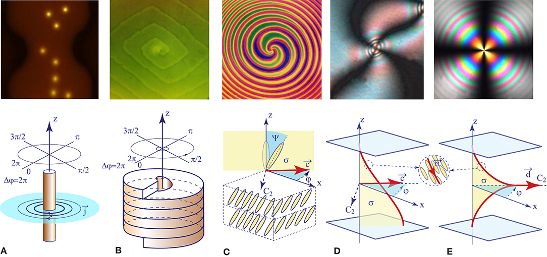
Figure 1. Topological defects in systems characterized by complex order parameters: (A) vortices in a superconductor [2], (B) dislocation in a BPI crystal, (C) disclination in a smectic C free-standing film, (D) umbilic in a homeotropic nematic layer above the Freedericks transition, (E) dowson in the dowser texture.
The dowser texture, known as the quasi-planar texture for decades [3], was believed unduly to be unstable, with respect to the homogeneous homeotropic texture, so that it has been scarcely studied in past. Recent work [4] proved that in practice the quasi-planar texture is only metastable and can be preserved indefinitely in certain conditions. Experiments with this persistent version of the quasi-planar texture have unveiled its remarkable qualities such as its sensitivity to magnetic [5], mechanical [6], or electric [7] perturbations. For this reason, as well because of the resemblance with the wooden dowser tool, the persistent version of the quasi-planar texture was dubbed “the dowser texture.”
1.2. Dowsons d+ and d−: the +2π and −2π Singularities of the Phase Field φ(x, y, t) of the Dowser Texture
The dowser texture is fully characterized by the azimuthal angle φ of the unitary two-dimensional dowser field d = (cosφ, sinφ) (Figure 1E) which is equivalent to the phase φ of the complex order parameter eiφ.
Thanks to the birefringence of nematics, the phase φ(x, y, t) of the dowser field d(x, y, t) is directly observable in polarized light so that its +2π and −2π topological singularities are easily identifiable [5]. Let us note that when considered in three dimensions of the nematic layer, these singularities of the 2D dowser field d(x, y) appear as nematic monopoles [8], that is to say, point singularities of the 3D director field n(x, y, z, t).
In the present work, devoted to motions and collisions of topological singularities of the dowser field we will call them shortly “dowsons.” Moreover, for the sake of concision, we will use notations “d+” and “d−” corresponding to the +2π and −2π versions of dowsons.
Let us stress that in contradistinction with the dowser texture, the phase φ(x, y) of the complex order parameter in superconductors is not an observable quantity and only its +2π and −2π singularities, that is to say vortices, can be imaged, for example, with a squid-tip AFM because they carry in their normal core the quanta of the magnetic flux h/(2e) [2].
1.3. Trajectories and Collisions of Dowsons
Previous experiments with dowsons [4, 5] have shown that pairs of dowsons “d+” and “d−” can be easily generated, set into motion and brought into collisions. In certain conditions collision of pairs of dowsons (d+,d−) can result in their annihilation. Here, we will explore these processes by means of especially tailored setups called “dowsons' colliders” (see section 2.1 and Figure 4).
The principal role of dowsons' colliders consists in driving motions of dowsons which is achieved by a controlled winding of the phase of the dowser field. Indeed, like vortices in superconductors which are set in motion by phase gradients (the Lorentz force is exerted on a flux quantum by a transport current proportional to the phase gradient), the motion of dowsons is also driven by phase gradients.
1.4. Single Dowsons Inserted in a Wound Up Dowser Field
This is explained on the first example shown in Figure 2 where one dowson d+ is imbedded in a wound up dowser texture. Before considering forces involved in the motion of this dowson d+, let us emphasize that its structure depends on the phase φi = φ(xi, yi) at the insertion point (xi, yi). Figures 2A–C show that for φi = 0 the structure of the dowson d+ is radial with the field d directed outward. For φi = π/2 the structure becomes circular anticlockwise (see Figures 2D–F) and for φi = π it is radial directed inward (see Figures 2G–I).
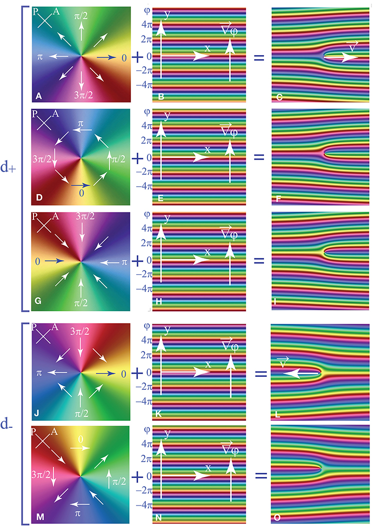
Figure 2. (A–I) Dowson +2π imbedded in a wound up dowser texture. (A,D,G) Radial, orthoradial, and antiradial configurations of the dowson d+ alone. The orthoradial configuration has the lowest elastic energy [5]. (B,E,H) Phase field of the dowser texture wound up in y direction: φ = 2πy/λ. (C,F,I) The wound up phase field with the dowson d+ imbedded respectively at y = 0 (C), y = λ/4 (F), and y=λ/2 (I). (J–O) Dowson -2π imbedded in a wound up dowser texture. (J,M) Configurations of the dowson d− depend on the phase φi = φ(xi, yi) at the insertion point (xi, yi). They result from rotation by the angle φi. (K,N) Phase field of the dowser texture wound up in y direction: φ = 2πy/λ. (L,O) The wound up phase field with the dowson d− imbedded respectively at y = 0 (L) and y=λ/4 (O).
In Figure 2 the dowser field is wound up in the y direction so that the phase φi = φ(xi, yi) does not depend on the coordinate xi of the insertion point. Therefore, lines defined by yi = const are isophasic and can be considered as isophasic trajectories of the dowson. In the general case of an arbitrarily wound up dowser field, one can still define isophasic lines by equation
When the dowson d+ is moving on such isophasic trajectories, its structure (radial, circular, or spiral) remains the same. Therefore, the isophasic trajectories can be alternatively called isoform. This second denomination is more convenient in practice: when the orientation of the cross-shaped isogyres of a dowson remains the same, its trajectory is isophasic.
Similar consideration on the insertion of one dowson d− into a wound up dowser field (illustrated by Figures 2J–O) leads to the conclusion that the “hyperbolic” structure of the dowson d− rotates as a whole when φi varies. Such a transformation of the dowson d− does not change its elastic energy so that trajectories of the dowson d− are not submitted to elastic constraints.
On the contrary, as stated above, the structure of the dowson d+ varies with φi. Therefore, due to the elastic anisotropy, the elastic energy of the dowson d+ depends on φi so that its trajectories are submitted to an elastic constraint. As we will point out below, dowsons d+ tend to follow isophasic trajectories.
In Figure 2C, the dowson d+ is located at the left extremity of a 2π wall. The elastic energy stored in this wall is relaxed when the dowson d+ moves to the right because the wall is shortened by this means.
Qualitatively, a wall of width λ exerts on the dowson d+ the force which is of the order of the elastic energy per unit length stored in it:
During the motion of the dowson with velocity v, the driving force τel is opposed by another one τvisc resulting from the viscous dissipation:
Therefore, the velocity of the dowson is given by:
In conclusion, the velocity of the dowson should be independent of the local thickness but should decrease as 1/λ with the local width λ of the wall.
When instead of the dowson d+, the dowson d− is imbedded in the same wound un dowser field (see Figure 2J), it is positioned at a right extremity of the 2π wall and therefore will move to the left.
1.5. Pair of Dowsons (d+,d−) Inserted in a Wound Up Dowser Field
Figure 3 represents the case of a pair of dowsons d+ and d− inserted in the same wound up dowser field. Analytically, the phase field of the wound up dowser texture with the pair of d+ and d− dowsons inserted respectively at points (x±, y±) can be expressed as
When the two dowsons are far enough, i.e., when |x+ − x−| > λ, they move on trajectories defined by y(t) = y+ and y(t) = y−. We can thus define the distance of trajectories as
in terms of the length or as
in terms of the phase. The set of seven pictures in Figures 3A–G illustrates graphically this concept of the distance of trajectories leading to collisions.
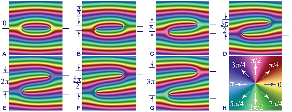
Figure 3. Collision of a pair of dowsons d+ and d− imbedded in a wound up dowser texture. The distance of their trajectories in terms of the phase difference Δφ varies between 0 to 3π from (A–G). The color code for the phase is given in (H).
1.6. Aims of Experiments With Dowsons' Colliders
One of aims of our experiments performed with dowsons' colliders is to find conditions which determine the outcome of collisions [9, 10]. When Δφ = 0 (see Figure 3A), the two dowsons are located at extremities of the same 2π wall. It seems therefore that annihilation of the (d+,d−) pair must occur. Inversely, when Δφ > π (see Figure 3G), the two dowsons are located at extremities of two distinct 2π walls so that the annihilation of such a pair will be avoided. We will thus generate experimentally numerous pair collisions with the aim to find the annihilation cross section of dowsons.
Before that, we will focus on the primary aim of our experiments which consists in observing motions of dowsons and measuring their velocities. Knowing that the elastic force driving their motion is inversely proportional to the wave length λ of the wound up texture, we have to wind up the dowser texture more or less expecting that the velocity of dowsons should increase when the phase gradient grows.
2. Dowsons' Colliders
2.1. Experimental Setups
2.1.1. The Double Dowsons' Collider
The first setup shown in Figure 4A, called here “Double Dowson Collider” or DDC, was developed during the study of the rheotropism of the dower texture [6]. It consists mainly of a convex lens (50 mm in diameter) and of a glass slide (25 × 75 × 1mm) supported at one end by a translation stage as shown in Figure 4A. The radius of curvature of the convex lens is 140 mm. A droplet of a nematic (5CB) is held by capillarity in the gap between the lens and the slide. Typically the diameter of the squeezed droplet is 10 mm and its thickness in the center (regulated by means of the translation stage) is of the order of a few μm. The glass slide is set into vibrations by the force exerted on small magnets by the magnetic field of the coil. Due to the mirror symmetry [with respect to the (x,z) plane] of this device, only the flexural modes of vibration ζ = ζ(x, t) are excited in it.
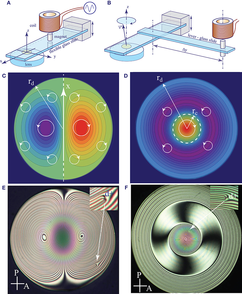
Figure 4. Dowsons' colliders. (A) The first version developed during studies of the rheotropism of the dowser texture [6]. Here, we will call it the Double Dowson Collider (DDC). (B) The second version tailored for production of circular trajectories of dowsons. We refer to it as the Circular Dowsons' Collider (CDC). (C,D) Approximative representations of the rheotropic torque Γ(x, y) in DDC and CDC. (E,F) Typical wound up dowser textures obtained with DDC and CDC.
As explained in Pieranski et al. [6], vibration of the slide (in its flexural modes) results in two harmonic motions at the drop center: 1—modulation of the gap thickness and 2—rotation around the y axis. By this means, two Poiseuille flows, radial and dipolar, shifted in phase by π/2, are driven simultaneously. The resulting effective flows are elliptical: clockwise and anticlockwise in the two halves of the droplet symmetrical with respect to the mirror plane (x,z).
The rheotropic (weathercock-like) behavior of the dowser field results in rotation of the dowser field d with the angular velocity ω(x, y, t) = dφ/dt depending on the (x,y) position in the droplet. In the DDC, the torque Γ(x,y,t) exerted by the elliptical Poiseuille flow on the dowser field can be approximated, heuristically, by the function fDDC(r) cos(θ), with , and θ = arctan(y/x), plotted in Figure 4C. A typical pattern of a wound up dowser texture observed in experiments between crossed polarisers is shown in Figure 4E. It is symmetrical with respect to the (x,z) plane.
2.1.2. The Circular Dowsons' Collider
For the purpose of the present study of collisions of dowsons, we developed a second setup (see Figure 4B) tailored for production of a circularly wound up pattern. As we will see below, trajectories of dowsons in this Circular Dowsons' Collider are circular and respectively clockwise and anticlockwise for the d+ and d− defects.
In this second setup, the mirror symmetry is broken by its structure. The magnet is now located at one extremity of an additional glass slide (10 × 75 × 1mm) which is attached at its second extremity to the principal glass slide. The force fexc exerted by the coil on the magnet produces now also a torque fexcΔy which drives the torsional mode of the principal glass slide. As the flexural and torsional modes have different eigenfrequencies, the π/2 phase shift between them can be obtained by an appropriate choice of the excitation frequency, which typically is of the order of 360–440 Hz. In such a case, the motion of the principal glass slide at the center of the drop is conical: the normal to it precesses on a cone centered on the z axis. The Poiseuille flow in the droplet is now circular (orthonormal) with the amplitude (and sense) depending on the distance r from the drop center.
In the first approximation, the torque Γ(x,y,t) exerted by the elliptical Poiseuille flow on the dowser field can be represented, heuristically, by the function fCDC(r) = d(fDDC/dr) which plotted in Figure 4D.
2.2. Experiments With the Double Dowsons' Collider
2.2.1. Velocity of Single Dowsons on Straight Trajectories
As shown in Figure 5E the isogyres' pattern of the dowser field wound up in the double dowsons' collider is (almost) symmetrical with respect to the mirror plane (x,z). Therefore, when a single dowson is imbedded in the wound up dowser field in the vicinity of this plane, the 2π wall to which it is attached is parallel to the x axis as discussed in the Introduction (see Figure 2). This is the case in the series of five pictures in Figures 5A–E showing the motion of a single dowson d+ “pulled” by a 2π wall along the x axis.

Figure 5. Motion of the dowson d+ in the phase gradient generated in the dowson collider DDC. The series of five pictures shows successive positions of the dowson d+ at: (A) t = 0 s, (B) t = 380 s, (C) 520 s, (D) 620 s, and (E) 700 s. For a better visibility, small areas in vicinity of the dowson have been enlarged in pictures (B–E). (F) Plot of the velocity of the dowson d+ vs. the local wave length of the wound up dowser texture. The continuous red line represents the fit to the power law v = Aλα with α = −1.24. The dashed blue line corresponds to α = −1.
These pictures are extracted from a video containing 55 pictures recorded at intervals of 20 s. Using all of them, we measured the velocity v of the dowson and the width λ of the 2π wall to which it is attached. The result, v(λ), is plotted in Figure 5F. Arrows labeled from a to e indicate measurement points corresponding to the five picture above.
From the Equation (4) in the section 1.4 we expect that the velocity of the dowson should grow as v ~ λ−1 with the local wave length λ of the wound up phase field. The dashed line in the diagram of Figure 5F represents the best fit to this law. Clearly, the slope of the measured variation v(λ) is slightly steeper. We have therefore tempted to fit experimental results with a more general power law v ~ λα. The continuous line represents the fit with α = −1.24 which clearly is better than the one with α = −1.
2.2.2. Dowsons' Sprint
In the search for reasons of this discrepancy, we performed another experiment which could be called “the dowsons sprint.” It starts with a simultaneous generation of a row of (d+,d−) pairs in a wound up dowser texture by means of a shear flow applied in the y direction (see Figures 6A,B). (We postpone the detailed discussion of this issue to another paper.) At t = 0 s, the dowsons d+ “in statu nascendi” are aligned on a slightly curved line AB while the dowsons d− are aligned on another line CD parallel to AB. As expected, all dowsons d+ start to move to the left while the dowsons d− move to the right.
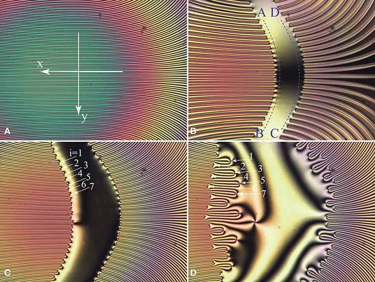
Figure 6. Dowsons race. (A) Central portion of the dowser texture wound up in the DDC. It can be seen as a stack of 2π walls. (B) Collective generation of (d+,d−) pairs by application of a transient shear flow (in y direction) which “breaks” simultaneously all 2π walls. (C) At the beginning of the race, dowsons d+ (or d−) are moving with the same velocity. (D) Odd-even instability: odd dowsons (i = 2n+1) stay behind even dowsons (i = 2n) because they become about three times slower. (Collaboration with Elise Hadjefstatiou and Lisa-Marie Montagnat).
For the purpose of the further discussion we will label seven neighboring dowsons d+ on the start line AB with an integer index i = 1,2,3,…(see Figure 6C).
At the very beginning of this race, the motion of dowsons is driven exclusively by shortening of the 2π walls connected to them, as discussed in the section 1.4. Therefore, they have therefore the same velocity vi = const and conserve their alignment on the curved line which is moving to the left as a whole.
However, soon after the departure, an instability occurs: the set of all dowsons is split into two subsets defined by the parity of the index i and, for example, dowsons with i odd (see Figure 6D) begin to move more slowly than those with i even. This retardation of odd dowsons (with i = 2n+1) is easy to understand: the width λ2n+1 of the 2π walls to which they are attached is twice larger then that of the even dowsons λ2n.
If the force fi pulling dowsons was determined only by the width λi of the 2π walls to which they are attached, the ratio of velocities v2n/v2n+1 should be 2. However, measurements of the dowsons' velocity have shown that v2n/v2n+1 ≈ 3.
Explanation of this apparent discrepancy involves a more detailed evaluation of the elastic energy released during the motion of dowsons. If the “lanes” left behind faster dowsons stayed free of distortion, the force acting on them would remain constant during the race. However, as shown in Figure 6D, these lanes are filled by enlargement of the lanes of slower dowsons. The corresponding amount of the released elastic energy per unit length is equal to the force f2n+1 pulling slower dowsons. In conclusion, the elastic force f2n acting on faster dowsons is not two but three times larger than f2n+1. A more detailed discussion of the dowsons' race is postponed to another article.
2.2.3. Are Trajectories of Dowsons Isophasic?
In experiments with dowsons' colliders, the 2π walls can be defined as bundles of four adjacent isogyres; when one crosses one of such bundles, the phase varies by 2π.
In the vicinity of the mirror symmetry plane (x,z) of the Double Dowson Collider, the 2π walls are parallel to the x axis so that the dowsons d+ and d− are moving on straight isophasic trajectories. However, as we know already from section 2.1 (see Figure 4C), the whole dowser texture, wound up in the Double Dowsons' Collider, can be seen as made of 2π walls forming closed loops in the absence of defects. Let us suppose that a pair (d+,d−) of dowsons has been generated by breaking one of these 2π walls. Pulled in opposite directions by the broken 2π wall these dowsons will move apart. Will their trajectories remain isophasic? If it was the case, they would remain connected to the same 2π wall which would became shorter and shorter so that, finally, the two dowsons would meet and annihilate. Such a behavior was indeed observed in first experiments with the dowser texture wound up by a rotating magnetic field [5].
As we will see below, experiments with dowsons' colliders have shown that trajectories of dowsons are not necessarily isophasic so that they do not remain connected to the same 2π wall. Therefore, when after a half turn of the wound up dowser texture the two dowsons of the pair meet again, the distance of their trajectories Δφ in terms of the phase is not necessarily zero so that their annihilation is not granted.
2.2.4. The First Evidence for Non-isophasic Trajectories of Dowsons
The issue of non isophasic trajectories of dowsons was raised for the first time in experiments with the DDC. Let us consider a typical experiment illustrated in the Figures 7A,B by a view of one of the two target patterns of the wound up dowser texture. We identify here four dowsons d+ and three dowsons d−. On this background we represented by rows of circular markers successive positions, recorded at intervals of 30 s, of dowsons d+ (Figure 7A) and d−(Figure 7B).

Figure 7. Trajectories of two dowsons, d+ and d−, in the DDC. Circular markers indicate successive positions of dowsons at time intervals of 30 s. Trajectories start from larger markers labeled “S” and end at markers labeled “E.” (A) The dowson d+ circulates in the clockwise direction of the phase winding. (B) The dowson d− circulates in the opposite, anticlockwise direction. Its trajectory starts in the vicinity of the center of the target pattern and ends at the periphery. Clearly such a trajectory is not isophasic. (C) Segment of the trajectory inside the dashed frame displayed in (A). (D) Blue crosses: velocity of the dowson d+ from (A) plotted vs. the width λ of the 2π wall pulling on it. Continuous blue line: the best fit to the power law with the exponent α = −1.14. Red crosses and the red line: reminder of the data from Figure 5. The dashed black line corresponds to α = −1.
Several conclusions can be drawn from this figure:
1. Dowsons d+ and d−, pulled by 2π walls, circulate in opposite directions, as expected.
2. The velocity of dowsons is correlated to the local width λ of 2π walls, as expected.
3. The trajectory of the dowson d+ is parallel to isogyres while the one of the dowson d− is crossing isogyres. In other words, the trajectory of the dowson d+ seems to be isophasic while that of the dowson d− is not isophasic.
4. The non isophasic behavior of dowsons d− is even more obvious when one considers the one labeled with a dashed circle in Figure 7. It is located in the center of the target pattern and this central position is dynamically stable during the phase winding. Now, as during the phase winding, the angular velocity ω = dφ/dt is the largest here, this central position is obviously not isophasic. Consequently, the maltese cross (formed by four isogyres) of this dowson is rotating as a whole with the angular velocity ω.
Knowing that the circular markers in Figure 7 indicate successive positions of dowsons at time intervals of 30 s, the velocity v of dowsons has been determined. Simultaneously the local width λ of the 2π walls pulling on dowsons has been measured in this Figure 7A. Results obtained with the dowson d+ are plotted with blue crosses in Figure 7D. The best fit to the power law v ~ λα plotted with the blue plain line was obtained with α = −1.14. On the same diagram of Figure 7D we have plotted once again (with red crosses and a red line) results shown previously in Figure 5.
2.3. Experiments With the Circular Dowsons' Collider
The most recent experiments performed with the Circular Dowsons' Collider confirmed these conclusions but also unveiled other remarkable properties of the dowsons dynamics. In particular, we have found that the result of the phase winding process in the Circular Dowsons' Collider depends on the initial state of the dowser field as well as on the amplitude of the excitation. In general, for topological reasons (homeotropic boundary conditions at the nematic/air interface of the meniscus), the dowser field can contain only an odd number 2n+1 of dowsons d+ and an even number 2n of dowsons d−. We will show below that two different dynamically stable states C-B1 or C-B2 can be reached when, respectively, n = 0 and n > 0.
2.3.1. Cladis-Brand Stationary State C-B1: One Dowson d+ Orbiting Around the Target Pattern
In the simplest case of n = 0, one dowson d+ is located initially at the center O of the drop and the dowser field has the radial configuration imposed by the cuneitropisme [4] of the dowser texture. This radial configuration also satisfies the homeotropic boundary conditions at the nematic/air interface on the edge of the droplet (see Figure 8A).
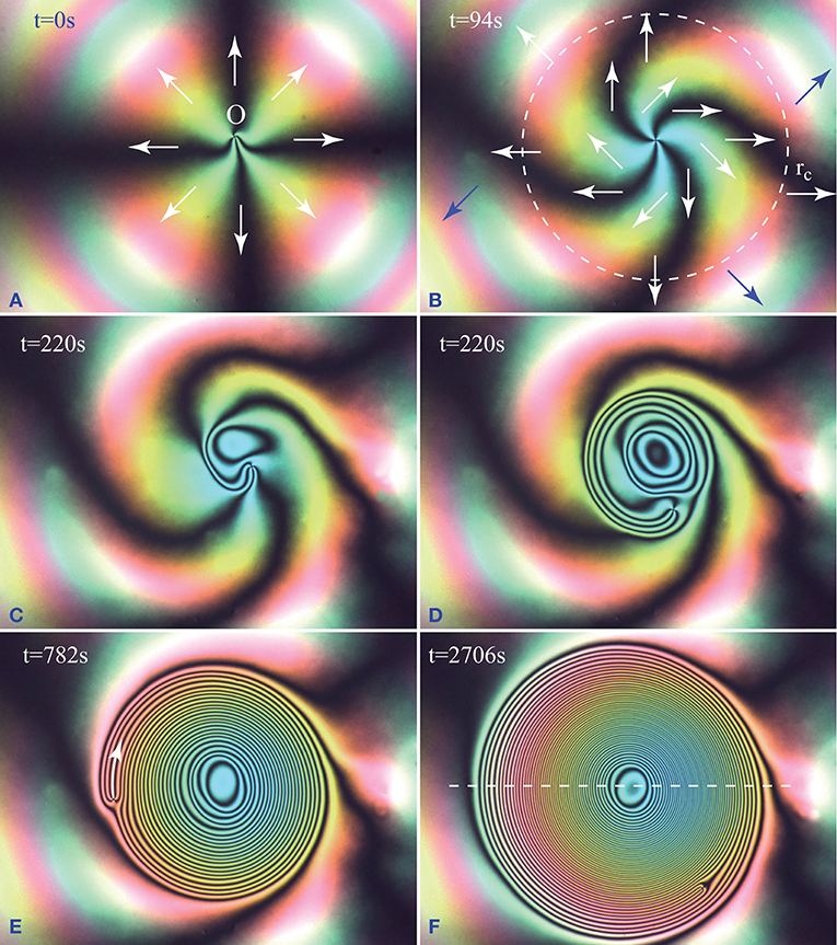
Figure 8. Cladis-Brand state C-B1 obtained by winding of the dowser texture in the Circular Dowsons' Collider. (A) Initial radial configuration of the dowser field. (B) Beginning of the winding in the anticlockwise direction. The initial configuration is slightly perturbed by a -π/2 rotation in the center. (C) The first isogyre nucleated in the center is growing. (D,E) Continuation of the winding. Remark: As for energetic reasons the dowson d+ cannot change easily its configuration, it conserves its phase staying at the periphery of the growing target pattern. (F) Dynamically stable Cladis-Brand state C-B1. The continuing phase growth in the center of the target pattern is absorbed by the orbiting dowson which acts as a phase sink.
When the rheotropic driving torque due to the circular Poiseuille flow is applied to the dowser field, it starts to rotate with the angular velocity ω(r, t), varying with the distance r from the center as shown in Figure 4D. Rotation of the dowser field is thus clockwise in the center at r=0, then the angular velocity ω(r, t) decreases and changes its sign at r = rc (dashed circle in Figure 8B). As a result, the maltese cross formed by four isogyres shown in Figure 8A is deformed: its four arms become spiral as shown in Figure 8B. Later, the dowson d+ leaves the center O and a target pattern of loop-like isogyres starts its growth from the center O: one after another, new isogyres' loops are nucleated at the center O and their radii are growing (see Figure 8).
If ω(0, 0, t) is the phase growth rate at the center O, then the rate of nucleation of 2π walls (each made of four isogyres) is ω(0, 0, t)/(2π).
During this winding process, the dowson d+ is pushed (elastically) by isogyres toward the periphery of the target pattern as shown in Figure 8. By this means, its position inside the evolving phase field φ(x, y, t) remains isophasic. This behavior results from the elastic anisotropy of the nematic. Indeed, as shown in Figure 2 the configuration of the dowson d+ depends on the phase φi at the point of its insertion into the wound up phase field. From Pieranski et al. [5] we know that the elastic energy of the dowson d+ depends on its configuration. As energetically the orthoradial configurations (clockwise or anticlockwise) are the best ones, the dowson tends to conserve its position at φ = π/2(modπ).
Simultaneously, pulled by the 2π wall to which it is attached, the dowson d+ begins its orbiting motion with velocity v (see Figure 8E) around the target pattern made of concentric 2π walls. The orbiting dowson d+ can be seen as a “phase sink”: after each whole turn around the target pattern, one 2π wall is “swollen.” If T is the period of the orbit, then we can define the phase sinking rate as 2π/T.
During the winding process, the phase growth rate ω(r, t) decreases because the rheotropic torque is opposed by the growing elastic torque. Simultaneously, the sinking rate increases because the orbiting dowson is moving faster pulled by the narrowing 2π wall.
The dynamically stable (stationary) phase field φ(x, y, t) is achieved when the phase growth rate at the center equals the sinking rate due to the orbiting dowson d+ : ω(0, 0, t) = 2π/T (see Figure 9). As Cladis and Brand have formerly discovered in free standing smectic C films the same configuration of a +2π defect orbiting around a target pattern [11] we propose to call it “The Cladis-Brand state 1” or shortly C-B1.
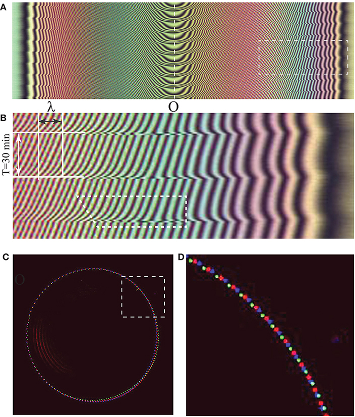
Figure 9. Cladis-Brand [11] dynamically stable state C-B1 of the phase winding in the Circular Dowsons' Collider. (A) Spatio-temporal cross section taken along the dashed line defined in Figure 8F. Four new isogyres are nucleated at the center O during one period T of the orbiting motion of the dowson d+. (B) Blow up of the rectangular domain defined with a dashed line in (A). λ is the width of a 2π wall composed of four oblique trajectories of isogyres. During one period T = 30 min, the 2π wall is shifted by λ to the right. (C) Successive positions of the dowson d+ recorded as colored dots at intervals of 10 s during three periods of its orbital motion. The three colors of dots correspond to the three periods T of the orbital motion. (D) Blow up of the rectangular domain defined with dashed line in (C).
2.3.2. C-B2: Second Version of the Cladis-Brand Stationary State
At first sight, upon the action of the rheotropic torque Γr(r), the dowser field should rotate in the anticlockwise direction for r > rc, rc being defined in Figure 4D. It seems therefore that new isogyres could nucleate also in the annular area near the second extremum of the torque Γr(r). In the experiment discussed above and illustrated by the series of six pictures in Figure 8, this is not the case: new isogyres nucleate only at the first extremum of Γr(r) located in the center O at r = 0.
Explanation of this experimental fact is very simple. Beside the rheotropic torque driving the rotation of the dowser field, there is also the cuneitropic torque Γc = (πK/h)g × d (see [4]) tending to orient the dowser field d in the direction of the thickness gradient g, that is to say in the radial direction r of the sphere/plane geometry of the sample (this is the case in Figure 8A). This cuneitropic torque vanishes at r=0 for symmetry reasons but is finite at r > rc. For a given r, it reaches its maximum value Γcmax = (πK/h(r))|g(r)| when d is orthogonal to g. In the experiment of Figure 8, for r > rc the rheotropic torque is smaller than Γcmax so that rotation of the dowser field is hindered there. In another experiment illustrated by the series of six pictures in Figure 10, the rheotropic torque was much larger so that nucleation of new isogyres occurred also in the secondary extremum of the rheotropic torque.

Figure 10. Generation of the second Cladis-Brand dynamically stable state by the phase winding in the Circular Dowsons' Collider. (A) At the beginning of the winding, the “residual” d+ dowson is close to the edge of the droplet. It is connected to the center O by a 2π wall. (B–D) Upon application of a strong excitation, the phase is wound up simultaneously in clockwise direction for r < rc and anticlockwise direction for r > rc. (E,F) Emergence of the second Cladis-Brand dynamically stable state with the dowson d+ orbiting around an extended double target pattern. The outer and inner target patterns are made of one spiral-shaped 2π wall connecting the dowson d+ with the center of the droplet.
2.3.3. Triplet Stationary State: Two Dowsons d+ Orbiting Around One d− in the Center
Experiments with the Circular Dowsons' Collider unveiled a third stationary state (see Figure 11). To reach it, the winding process has to be applied to the dowser field with n>0, that is to say containing at least two dowsons d− and one dowson d+ when n = 1.
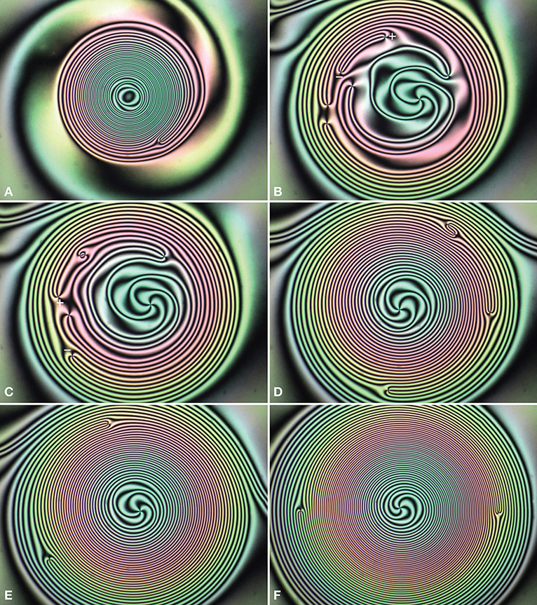
Figure 11. Generation of the dynamically stable “triplet” configuration of dowsons during the phase winding in the Circular Dowsons' Collider. (A) First, the Cladis-Brand configuration of one orbiting d+ dowson is generated as shown in Figure 8. (B) Application of a transitory shear flow to the Cladis-Brand state results in generation of three additional dowsons pairs (d+,d−). One these pairs is labeled as “+” and “−.” (C) Annihilation of the (d+,d−) pair labeled in (B). The second (d+,d−) pair is labeled as “+” and “−.” (D) Annihilation of the (d+,d−) pair labeled in (C). Only three dowsons are left. (E) Continuation of the winding process. (F) Dynamically stable trio of three dowson: two dowsons d+ are orbiting around the dowson d− which stays in the center.
For reasons which so far have been not fully understood, during the winding, the dowson d− is attracted to the center O [maximum of ω(r, t)] and stays there while the two dowsons d+, on the contrary, are pushed to the periphery of the growing pattern. Let us emphasize that in this new configuration the winding process does not require nucleation of new isogyres. The phase growth in the center is now due to rotation of the dowson d− located there. This mechanism is similar to the Frank-Read model of crystal growth in which a spiral step, attached to a dislocation emerging on a crystal facet, is rotating.
When n is larger than 1, the (d+,d−) pairs in excess with respect to n = 1 are eliminated by annihilation during the winding process as shown in Figures 11B–D.
Like in the Cladis-Brand process, the stationary triplet state is reached when the phase growth rate in the center, due to the rotation of the dowson d−, is fully compensated by the orbital motion of the two dowsons d+ acting as phase sinks. In this stationary state, the two dowsons d+ are located on the same orbit (see Figure 12D) and have therefore the same angular velocity ωd+. The total phase absorption rate is therefore 2ωd+. Therefore, if the d− dowson in the center rotates with the angular velocity ωd− then in the stationary state one has:
so that
This equality is illustrated by in Figures 12A,B.
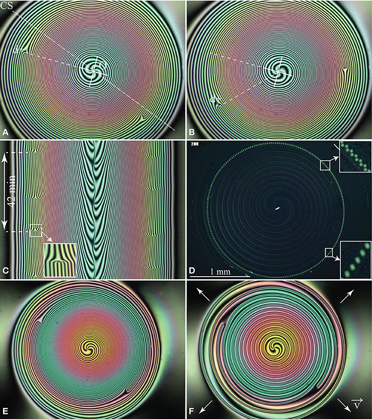
Figure 12. Dynamics of the stable triplet configuration of dowsons. (A,B) Two pictures of the wound up dowser texture taken at an interval of 5 min. In this interval, the dowson d− in the center rotated by π/2, while the dowson d+ on their orbits made only 1/8th of the whole turn. (C) Spatio-temporal cross section taken along the dashed line CS defined in (A). The inset shows that the orbiting dowson d+ acts as a phase sink: after each crossing of the line CS by one of orbiting dowsons d+, four isogyres are suppressed. Simultaneously four new isogyres are emitted by the dowson d− rotating in the center O. (D) Successive positions of the two dowsons d+ recorded at intervals of 10 s during one period of their orbital motions. The two inset show that velocities of the two dowsons d+ are the same. (E,F) To check that the two dowsons d+ are isophasic, a divergent Poiseuille flow was applied to the wound up dowser field shown in (E).
3. Generation, Collisions, and Annihilation of Dowsons' Pairs
The dynamically stable states of the Circular Dowsons' Collider are convenient for studies of generation of dowsons and of their subsequent collisions which can lead to annihilation. Indeed, like positrons and electrons in a hadron collider, dowsons d+ and d− are moving in the Circular Dowsons' Collider on respectively clockwise and anticlockwise trajectories so that they can undergo collisions that can result in annihilation of dowsons pairs.
By a collision we mean an event during which the linear distance l+− between two dowsons, d+ and d−, decreases and becomes of the order of the winding wave length λ.
3.1. Generation of One (d+,d−) Pair
For the purpose of clarity of the forthcoming discussion, let us consider the example represented in Figure 13 which shows in the Figure 13A, a view of the wound up dowser field shortly after generation of just one dowsons pair. The process of generation itself is illustrated by the series of five pictures (Figures 13C–G). It is triggered by a rapid and short forth-and-back motion of the oscillating glass slide applied to the wound up texture visible in Figure 13C. During the motion, the image of the isogyres' pattern becomes fuzzy (Figure 13D) but shortly after that, at the beginning of the relaxation (Figure 13E), one can distinguish seven 2π walls thinned by the perturbation.
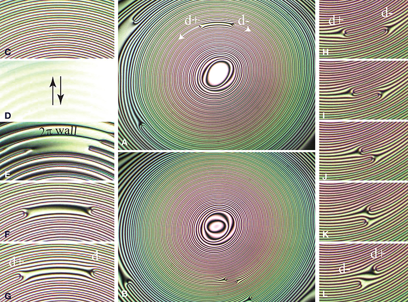
Figure 13. Generation and collision of a dowsons' pair in the Circular Dowsons Colider. (A) Wound up dowser field with a pair of dowsons “in statu nascendi.” (B) After a half turn of their orbits, the d+ and d− dowsons are coming to a collision. (C–G) Generation of the dowsons pair. (H–L) Collision of the pair without annihilation.
As discussed in Pieranski et al. [6] thinning of 2π walls is due to the rheotropism of the dowser texture, that-is-to-say, to its sensitivity to Poiseuille flows. Anticipating a more detailed discussion in section 3.5 we infer that at the beginning of the relaxation a transitory Poiseuille flow 2π walls occurred.
An excessive thinning of one of the 2π walls leads to its breaking shown in Figure 13E. Subsequently the two dowsons generated by this means are moving in opposite directions on initially isophasic trajectories.
3.2. Collision of a (d+,d−) Pair
As the isogyres pattern in the wound up Cladis-Brand state is made of concentric rings, one could think that after a half turn of their orbits (see Figure 13B), the freshly generated dowsons should come to a collision on isophasic trajectories. The series of five pictures (Figures 13H–I), shows clearly that this is not the case: there is a Δφ ≈ 2π distance (see Figure 13H), in terms of the phase, between trajectories of the two dowsons coming to their collision. We postpone discussion of this paradox to another paper.
In meantime, let us just say that the two dowsons coming to collision are pulled by two distinct 2π walls so that annihilation is avoided.
3.3. Rules for Collisions of (d+,d−) Pairs
When more than one pair of dowsons is generated simultaneously, the subsequent collisions occur at variable distances Δφ of trajectories. From observations of many of such collisions with −2π < Δφ < +2π we inferred the following rules:
1. Bypass: When |Δφ| > π, the annihilation is avoided and the dowsons are passing by (see Figures 14A–I).
2. Annihilation: When |Δφ| < π, the annihilation occurs (see Figures 14J–R).
3. Critical: When |Δφ| = π, the outcome of the collision is random.
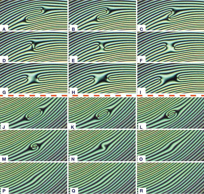
Figure 14. Criterium for the outcome of collisions. (A–I) When |Δφ| > π, annihilation is avoided. Here, |Δφ| ≈ 3π/2. Pictures taken at intervals of 10 s. (J–R) When |Δφ| < π, annihilation occurs. Here, |Δφ| ≈ π/2. Pictures taken at intervals of 5 s.
3.4. Influence of Poiseuille Flows on Collisions of Dowsons Pairs, Experiment
The rules formulated above apply to pairs of dowsons moving inside a very slowly evolving stationary wound up dowser field.
Knowing from former experiments that the dowser texture is very sensitive to Poiseuille flows [6] we used this property, called rheotropism, to influence the outcome of dowsons collisions. As an example we point out in the series of 20 pictures in Figures 15A–T that the annihilation, which should occur in terms of the collisions' rules applied to the pair of dowsons in Figure 15A, can be avoided by application of a Poiseuille flow in an appropriate direction.
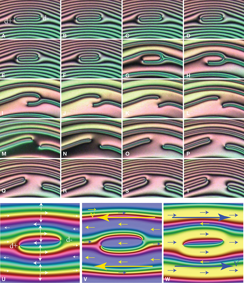
Figure 15. Influence of Poiseuille flows on collisions of dowsons. (A–T) Experiment. Evolution of the dowser field before, during and after application of a Poiseuille flow. (U–W) Simulation. Pair of dowsons without flow (U) and in the presence of flows in left and right drections.
Indeed, at the beginning of the experiment (see Figures 15A–D) dowsons d+ and d− coming to collision are almost isophasic and are connected by a 2π wall which is shortening. The outcome of the forthcoming collision seems unavoidable: an annihilation. However, an application of the Poiseuille flow in the left direction [parallel to the dowser field in the middle of the wall (d+,d−)], has a very striking effect well visible in pictures Figures 15E–L: the wall connecting the dowsons pair as well as the whole system of isogyres is split in such a manner that the two dowsons are reconnected to two new, different 2π walls. These walls, narrowed by the Poiseuille flow, pull strongly on dowsons which move rapidely on distinct trajectories separated now by 2π, in terms of the phase. After cessation of the flow (Figures 15M–T) the system of isogyres relaxes: the trajectories of the two dowsons become almost isophasic again but they diverge now.
3.5. Influence of Poiseuille Flows on Collisions of Dowsons Pairs, a Model
Theoretically, this experiment can be modeled as follows. At the beginning of the experiment, the phase field can be is expressed as before (see Equation 5):
with (x+, y+) = (−5, −π/4) and (x−, y−) = (5, π/4) so that
This initial field is depicted in Figure 15U using the color code defined in Figure 2A. Application of the Poiseuille flow of the amplitude vmax in the -x direction perturbs the field φo(x, y). The rheotropic torque exerted by this Poiseuille flow on the field φ(x, y)o can be written as:
In the first approximation, the resulting elastic distortion is proportional to this torque so that the perturbed phase field can be written as:
with δφ ~ vo. The graphic representation of φpert(x, y) in Figure 15V shows an agreement with the experimental picture in Figure 15I.
Let us stress that when the Poiseuille flow is applied in the inverse, +x direction, our model predicts that the 2π wall connecting the dowsons' pair is no split but narrowed as shown in Figure 15W so that the annihilation is accelerated.
These simulations are in agreement with our experiments: the outcome of the forthcoming collisions can be chosen at will by application of Poiseuille flows in appropriate directions.
4. Conclusions
The present paper is by no means exhaustive in the matter of generation, motions, and collisions of dowsons. Nevertheless, it raises new issues concerning (1) laws of motion of dowsons driven by phase gradients and (2) laws ruling the outcome of dowsons' collisions.
In particular, there is a huge difference in the behavior of dowsons d+ and d− during phase winding. The dowsons d+ cannot rotate because of the elastic anisotropy so that they tend to escape from the winding up phase field and are going to areas where the phase growth rate is zero. In the case of a unique dowson d+, this leads to the Cladis-Brand stationary states in which the orbiting dowson d+ absorbs the phase generated by the dowsons' collider.
The behavior of the dowson d− seems to be a contrary one and much more enigmatic. Indeed, experiments showed that during the winding process the dowsons d− is attracted to the area in which the phase growth rate is maximal. By this means another stationary state, with the dowson d− in the center (acting as a phase source) and two dowsons d+ orbiting around it (acting as phase sinks), can be reached. This gyrophilic behavior of the dowson d− remains to be explained.
The law ruling translational motion of dowsons on their orbits needs also further clarification. Theoretically, in the first approximation, the velocity v of dowsons should be proportional to the local phase gradient ∇φ = 2π/λ: v ~ λα with α = −1. Experiments have shown however that in practice the exponent α is smaller than −1. This discrepancy is probably due to interactions between moving dowsons which certainly play the major role during the dowsons sprint discussed in section 2.2.2.
From observations of dowsons pairs (d+d−) moving on counter-rotating orbits, a rule for the outcome of their collisions, i.e., either annihilation or bypass, was inferred. The distance of trajectories Δφ in terms of the phase appeared as the pertinent parameter: for Δφ < π a collision of a pair of dowsons leads to their annihilation, while for Δφ > π the dowsons are passing by. However, this rule is valid only for quasi-static stationary wound up textures and can be easily broken by application of a Poiseuille flow in an appropriate direction.
Data Availability Statement
The datasets generated for this study are available on request to the corresponding author.
Author Contributions
All authors listed have made a substantial, direct and intellectual contribution to the work, and approved it for publication.
Funding
PP was indebted to S. Ravy for a financial support. MG thanks FCTPortuguese Foundation for Science and Technology under projects UID/CTM/50025/2013, and PTDC/CTM-BIO/6178/2014 and M-ERA-NET2/0007/2016 (CellColor).
Conflict of Interest
The authors declare that the research was conducted in the absence of any commercial or financial relationships that could be construed as a potential conflict of interest.
Acknowledgments
Our interest in physics of dowsons was stimulated by fruitful interactions with L. Giomi [12], T. Lubensky, and V. Vitelli during the Lorentz Workshop on Topology in Complex Fluids hold in Leiden in 2018. We acknowledge a fruitful collaboration with Elise Hadjefstatiou and Lisa-Marie Montagnat during experiments on the dowsons' race. This work benefited from the technical assistance of I. Settouraman, V. Klein, S. Saranga, J. Sanchez, M. Bottineau, J. Vieira, I. Nimaga, and C. Goldmann.
References
2. Embon L, Anahory Y, Jelić ZL, Lachman EO, Myasoedov Y, Huber ME, et al. Imaging of super-fast dynamics and flow instabilities of superconducting vortices. Nat Commun. (2017) 8:85. doi: 10.1038/s41467-017-00089-3
3. Gilli JM, Thiberge S, Vierheilig A, Fried F. Inversion walls in homeotropic nematic and cholesteric layers. Liquid Cryst. (1997) 23:619–28. doi: 10.1080/026782997207894
4. Pieranski P, Godinho MH, Čopar S. Persistent quasi-planar nematic texture: its properties and topological defects. Phys Rev E. (2016) 94:042706. doi: 10.1103/PhysRevE.94.042706
5. Pieranski P, Čopar S, Godinho MH, Dazza M. Hedgehogs in the dowser state. Eur Phys J E. (2016) 39:121. doi: 10.1140/epje/i2016-16121-7
6. Pieranski P, Hulin JP, Godinho MH. Rheotropism the dowser state. Eur Phys J E. (2017) 40:109. doi: 10.1140/epje/i2017-11598-0
7. Pieranski P, Godinho MH. Flexo-electric polarisation of the dowser texture. Soft Matter. (2019) 15: 1459–694. doi: 10.1039/C8SM02329H
8. Kleman M, Lavrentovich OD. Topological point defects in nematic liquid crystals. Philos Mag. (2006) 86:4117–37. doi: 10.1080/14786430600593016
9. Cladis PE, Brand HR. Hedgehog-antihedgehog pair annihilation to a static soliton. Phys A. (2003) 326:322–32. doi: 10.1016/S0378-4371(03)00254-1
10. Svetec M, Kralj S, Bradač Z, Žumer S. Annihilation of nematic point defects: pre-collision and post-collision evolution. EPJE. (2006) 20:71–9. doi: 10.1140/epje/i2005-10120-9
11. Cladis PE, Finn PL, Brand HR. Stable coexistence of spiral and target patterns in freely suspended films of smectic-C liquid crystals. Phys Rev Lett. (1995) 75:1518–21. doi: 10.1103/PhysRevLett.75.1518
Keywords: nematic, topological defects, dowser texture, complex order parameter, collider, annihilation
Citation: Pieranski P and Godinho MH (2020) On Generation, Motions, and Collisions of Dowsons. Front. Phys. 7:238. doi: 10.3389/fphy.2019.00238
Received: 11 September 2019; Accepted: 16 December 2019;
Published: 14 January 2020.
Edited by:
Teresa Lopez-Leon, École Supérieure de Physique et de Chimie Industrielles de la Ville de Paris, FranceReviewed by:
Simon Čopar, University of Ljubljana, SloveniaThomas Machon, University of Bristol, United Kingdom
Copyright © 2020 Pieranski and Godinho. This is an open-access article distributed under the terms of the Creative Commons Attribution License (CC BY). The use, distribution or reproduction in other forums is permitted, provided the original author(s) and the copyright owner(s) are credited and that the original publication in this journal is cited, in accordance with accepted academic practice. No use, distribution or reproduction is permitted which does not comply with these terms.
*Correspondence: Pawel Pieranski, cGF3ZWwucGllcmFuc2tpJiN4MDAwNDA7dS1wc3VkLmZy